motor control with arduino - universidad de...
TRANSCRIPT
1 © 2013 The MathWorks, Inc.
Motor Control with Arduino
A Case Study in Data-Driven Modeling and Control Design
Toledo, 22-II-2013
4
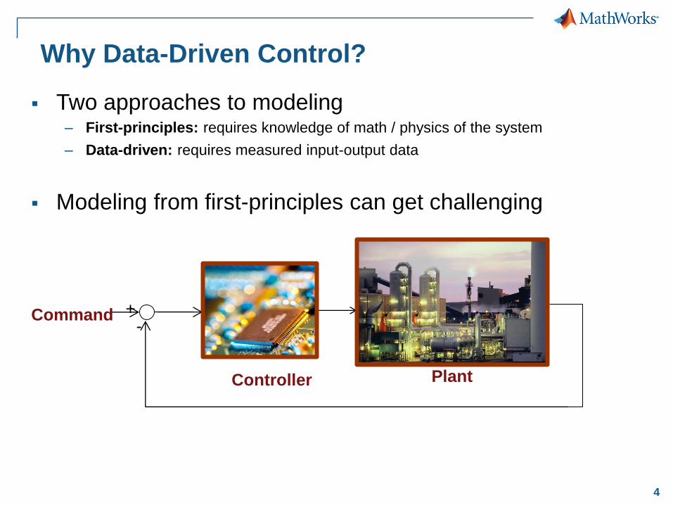
Why Data-Driven Control?
Two approaches to modeling – First-principles: requires knowledge of math / physics of the system
– Data-driven: requires measured input-output data
Modeling from first-principles can get challenging
Plant Controller
+ -
Command
Data-Driven Modeling First Principles Modeling
Neural Networks
Physical Networks System
Identification
Parameter Tuning
Programming
Block Diagram
Modeling Language
Symbolic Methods
Modeling Approaches
Statistical Methods
(MATLAB, C)
(Simulink)
(Simscape language)
(Symbolic Math Toolbox)
(Simscape and other
Physical Modeling
products)
(Neural Network
Toolbox)
(Model Based
Calibration Toolbox)
(Simulink Design Optimization)
(System Identification Toolbox)
5
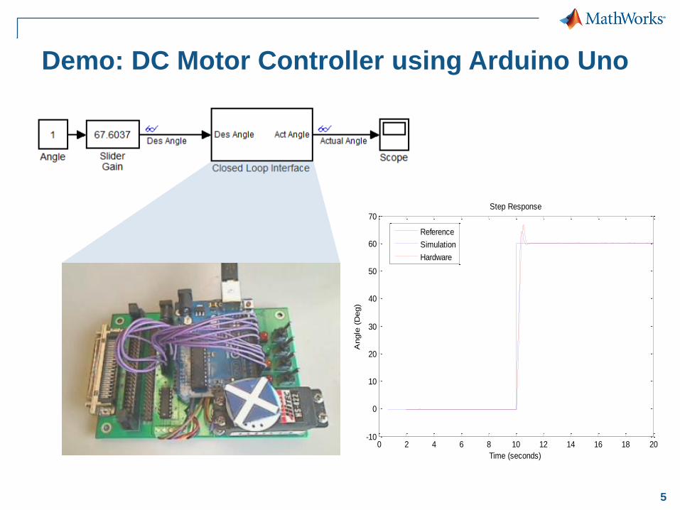
Demo: DC Motor Controller using Arduino Uno
0 2 4 6 8 10 12 14 16 18 20-10
0
10
20
30
40
50
60
70Step Response
Time (seconds)
Angle
(D
eg)
Reference
Simulation
Hardware

6
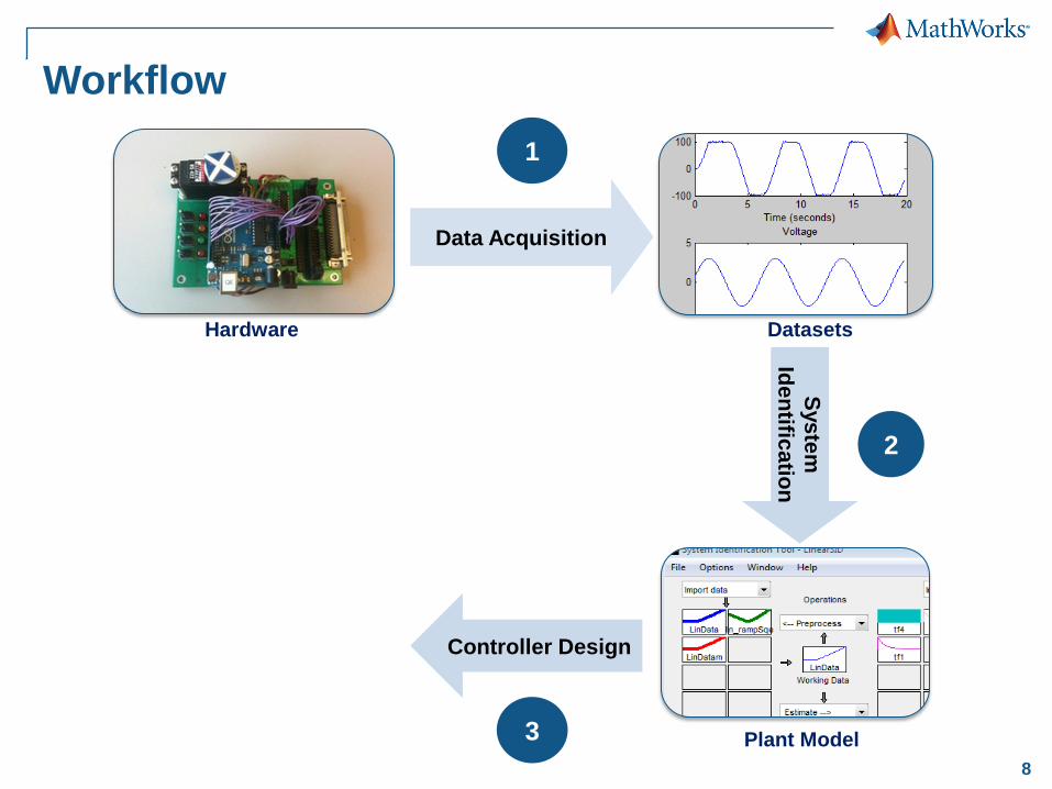
Workflow
Hardware Datasets
Control System Plant Model
Sys
tem
Ide
ntific
atio
n R
ea
l-T
ime
Te
sti
ng
Controller Design
Data Acquisition
1
4
3
2

7
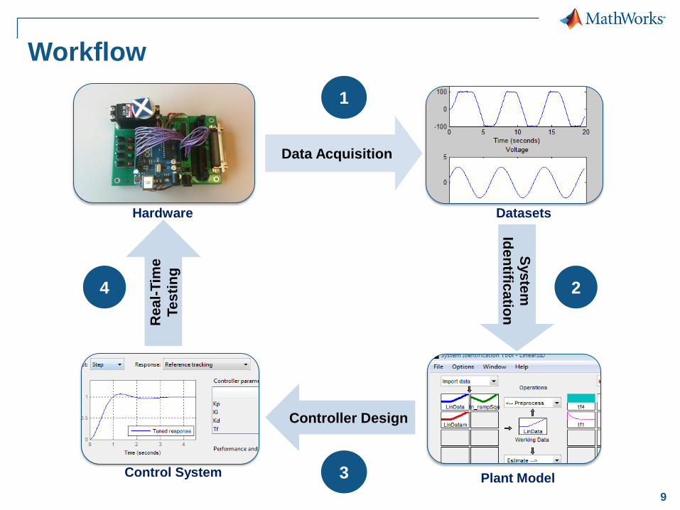
Workflow
Hardware Datasets
Control System Plant Model
Sys
tem
Ide
ntific
atio
n R
ea
l-T
ime
Te
sti
ng
Controller Design
Data Acquisition
1
4
3
2
8
Workflow
Hardware Datasets
Control System Plant Model
Sys
tem
Ide
ntific
atio
n R
ea
l-T
ime
Te
sti
ng
Controller Design
Data Acquisition
1
4
3
2
9
Workflow
Hardware Datasets
Control System Plant Model
Sys
tem
Ide
ntific
atio
n R
ea
l-T
ime
Te
sti
ng
Controller Design
Data Acquisition
1
4
3
2
10
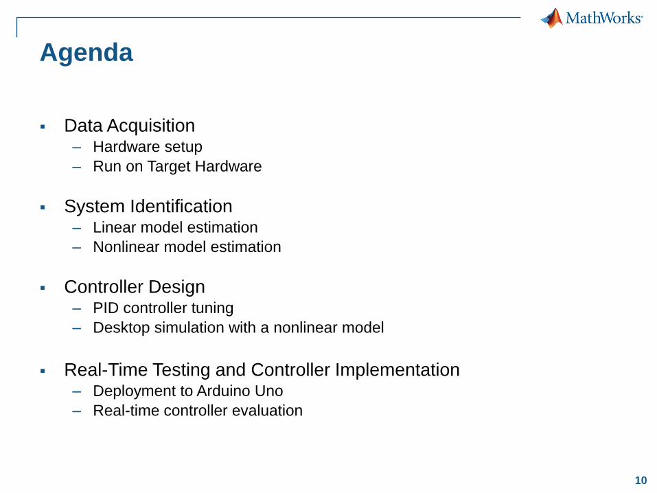
Agenda
Data Acquisition – Hardware setup
– Run on Target Hardware
System Identification – Linear model estimation
– Nonlinear model estimation
Controller Design – PID controller tuning
– Desktop simulation with a nonlinear model
Real-Time Testing and Controller Implementation – Deployment to Arduino Uno
– Real-time controller evaluation
11
DATA ACQUISITION
12
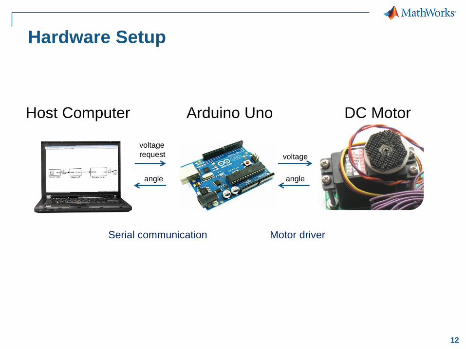
Hardware Setup
Host Computer Arduino Uno DC Motor
Serial communication Motor driver
voltage
request
angle
voltage
angle
13
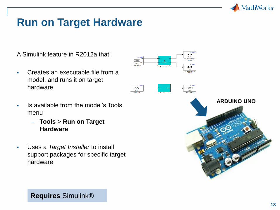
Run on Target Hardware
A Simulink feature in R2012a that:
Creates an executable file from a
model, and runs it on target
hardware
Is available from the model’s Tools
menu
– Tools > Run on Target
Hardware
Uses a Target Installer to install
support packages for specific target
hardware
ARDUINO UNO
Requires Simulink®
14
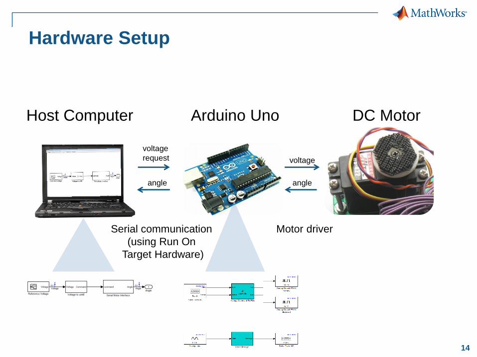
Hardware Setup
Host Computer Arduino Uno DC Motor
Serial communication
(using Run On
Target Hardware)
Motor driver
voltage
request
angle
voltage
angle
15
SYSTEM IDENTIFICATION
16
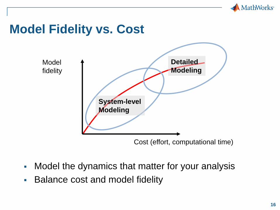
Model Fidelity vs. Cost
Model the dynamics that matter for your analysis
Balance cost and model fidelity
Cost (effort, computational time)
Model
fidelity
Detailed
Modeling
System-level
Modeling

17
Linear System Identification
Create continuous-time
transfer functions from data
Use either time or frequency
domain data containing an
arbitrary number of inputs
and outputs
Estimate other linear models:
state-space, process models,
and parametric models
Requires System Identification Toolbox™
18
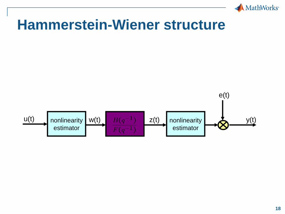
Hammerstein-Wiener structure
nonlinearity
estimator
e(t)
u(t) y(t) nonlinearity
estimator
w(t) z(t)
19
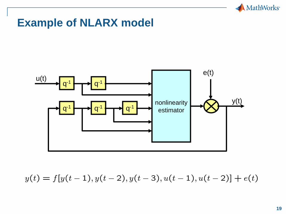
Example of NLARX model
q-1 q-1
q-1 q-1 q-1 nonlinearity
estimator
e(t) u(t)
y(t)
20
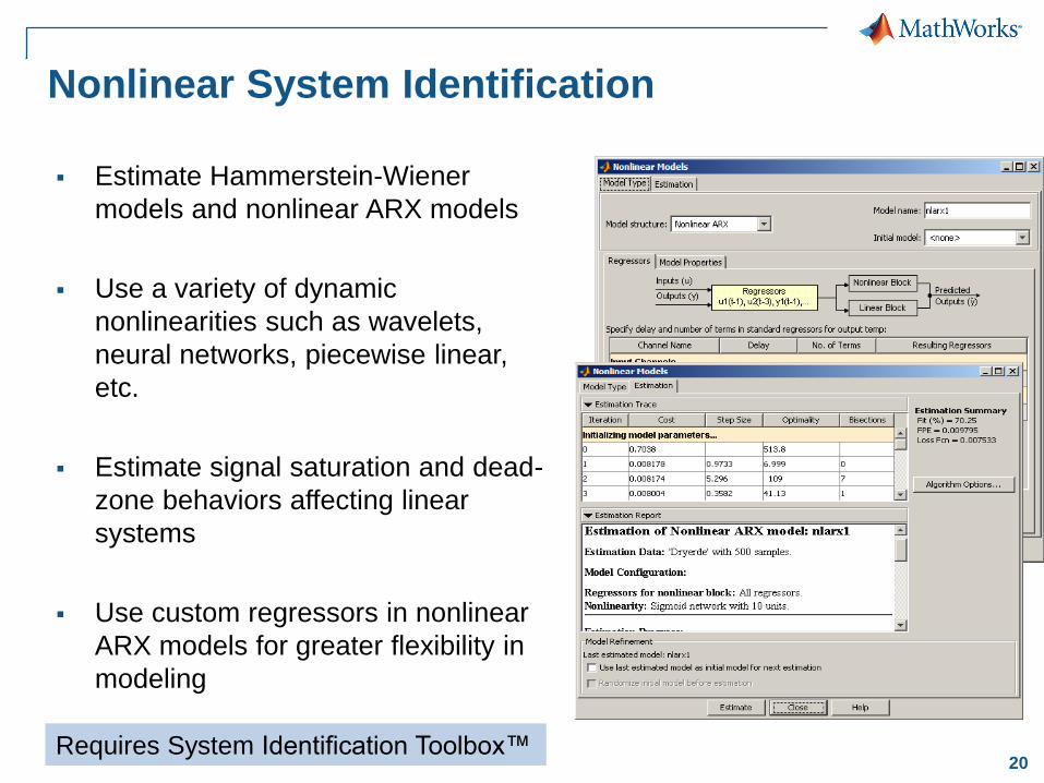
Nonlinear System Identification
Estimate Hammerstein-Wiener
models and nonlinear ARX models
Use a variety of dynamic
nonlinearities such as wavelets,
neural networks, piecewise linear,
etc.
Estimate signal saturation and dead-
zone behaviors affecting linear
systems
Use custom regressors in nonlinear
ARX models for greater flexibility in
modeling
Requires System Identification Toolbox™
21
CONTROLLER DESIGN
22
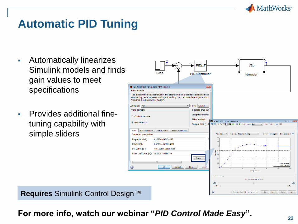
Automatic PID Tuning
Automatically linearizes
Simulink models and finds
gain values to meet
specifications
Provides additional fine-
tuning capability with
simple sliders
For more info, watch our webinar “PID Control Made Easy”.
Requires Simulink Control Design™
23
REAL-TIME TESTING AND
CONTROLLER IMPLEMENTATION

25
Real-Time Testing
Host Computer Arduino Uno DC Motor
Serial communication
(Using Run On
Target Hardware)
Motor driver
angle
request
angle
voltage
angle

26
Workflow
Hardware Datasets
Control System Plant Model
Sys
tem
Ide
ntific
atio
n R
ea
l-T
ime
Te
sti
ng
Controller Design
Data Acquisition
1
4
3
2
27
Summary
MATLAB and Simulink support data-driven control
design
MATLAB and Simulink provide an environment for
– Data acquisition
– System identification
– Control design
– Real-Time testing