motorized switch-disconnectors otm f - abb group · only an authorised electrician may perform the...
TRANSCRIPT

Installation instruction34OTM_F_ / 1SCC303010M0202
Motorized switch-disconnectors OTM_F_

31SCC303010M0202, rev. B
Installation instruction, OTM_F_Contents
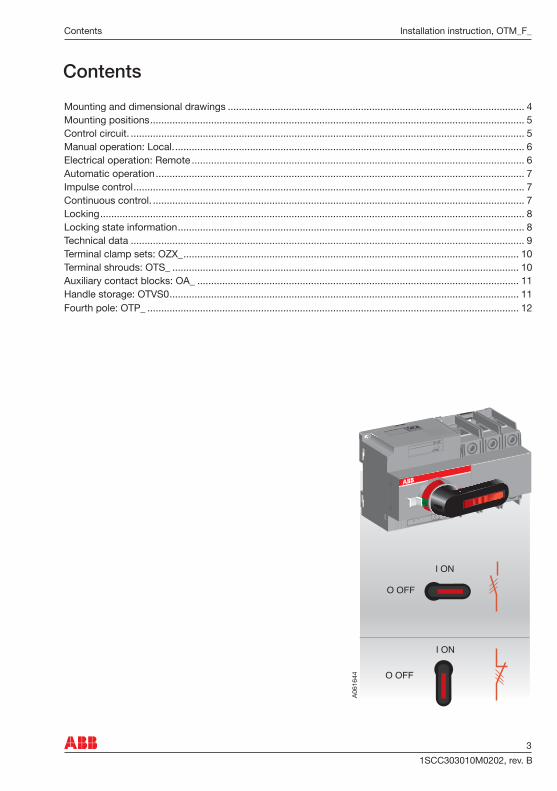
Contents
A061
644 O OFF
I ON
O OFF
I ON
II
Mounting and dimensional drawings ........................................................................................................... 4Mounting positions ....................................................................................................................................... 5Control circuit. .............................................................................................................................................. 5Manual operation: Local. .............................................................................................................................. 6Electrical operation: Remote ........................................................................................................................ 6Automatic operation ..................................................................................................................................... 7Impulse control ............................................................................................................................................. 7Continuous control. ...................................................................................................................................... 7Locking ......................................................................................................................................................... 8Locking state information ............................................................................................................................. 8Technical data .............................................................................................................................................. 9Terminal clamp sets: OZX_ ......................................................................................................................... 10Terminal shrouds: OTS_ ............................................................................................................................. 10Auxiliary contact blocks: OA_ .................................................................................................................... 11Handle storage: OTVS0 .............................................................................................................................. 11Fourth pole: OTP_ ...................................................................................................................................... 12

1SCC303010M0202, rev. B4
Installation instruction, OTM_F_ Mounting and dimensional drawings: OTM30-125F_C_
1
Note:Use protection against direct contact.For example:
OTM402,5...25 mm2 / 2 x 2,5 -16 mm2
14...4 AWG / 2 x 14 - 6 AWG
OTM63-12510...70 mm2 8...2/0 AWG
EN 50022
351.38
A061
31
3
Fuse Reset
Remove
2
IIOTM
IIOTM
80 12 56
90
M43 Nm26.6 lb.in.
ø 4,5DIA0.18
6 Nm55 lb.-in.
4 mm0.16 in
OTM
14-15 mm0.55-0.59 in
OTM30-125F_M
11 14
OTM
45
5 80 12 567
33,5
Ø4,540
5222,5 26
60
9065
11699
83
100
35
6,5 44
35
EN50022
75
10M
0035
3/O
TM
30-1
25F
_M
B
65
12160 ( 3-pole )186,5 ( 4-pole )
12
16
74,5
-
PE N I 0L
+
C
Fuse Reset
14

51SCC303010M0202, rev. B
Installation instruction, OTM_F_Mounting positions, Control circuit
Mounting positions
Control Circuit
A061
32
11 14
OTM
-
PE N I 0L
+
C
Fuse Reset
1114
OT
M
-
PE
NI
0L +
C
Fuse
Res
et
Only an authorised electrician may perform the electrical installation and maintenance of motorized switch. Do not attempt any installation or maintenance actions when a motorized switch is connected to the electrical mains. Before starting work, make sure that the switch is de-energised.
Do not couple power for the control terminal. See the correct terminal for the power supply.
1. Terminal for motor operator voltage supply2. Control terminal for push buttons3. Terminal for state information of locking
II
A061
331 PE N L
F2
21
B
A C
C I 0
3
3
11 14
224 Vdc

1SCC303010M0202, rev. B6
Installation instruction, OTM_F_ Manual operation: Local, Electrical operation: Remote
Electrical operation is prevented when the handle is attached to the switch panel.
IIII
A061
34
1 2CLICK !
Never open any covers on the product. There may be dangerous external control voltages inside the motorized switch even if the voltage is turned off.
Never handle control cables when the voltage of the motorized switch or external control circuits are connected.
Fuse Reset
OTM
Fuse Reset
OTM
A061
35
41OTM
IIFuse Reset OTM
I
OTM
Fuse Reset
3
2
Fuse Reset
OTM
Manual operation: Local
Electrical operation: Remote
71SCC303010M0202, rev. B
Installation instruction, OTM_F_Electrical operation: Resetting Fuse. Impulse control, Continuous control
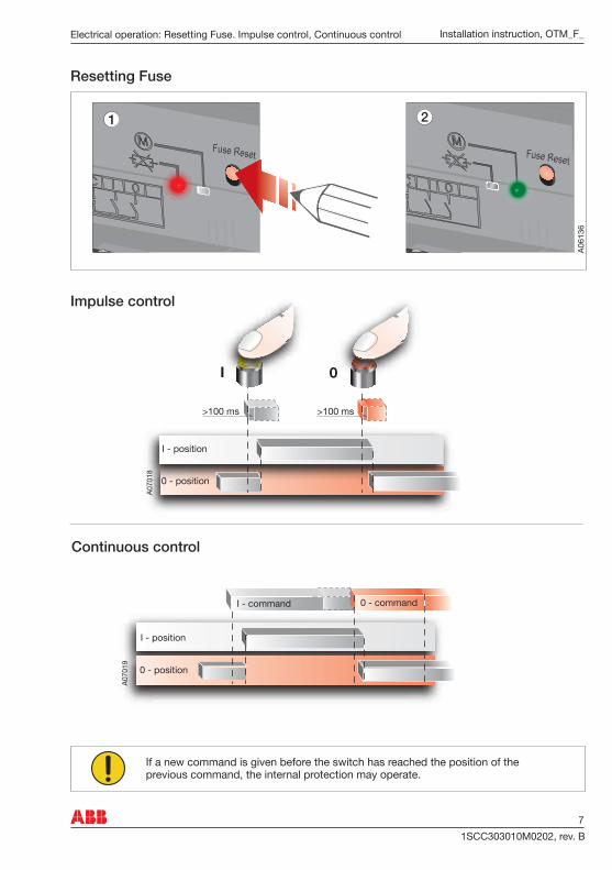
Resetting Fuse
Impulse control
Continuous control
IIFuse Reset
2
A061
36
Fuse Reset
21
I - position
0 - position
0I
If a new command is given before the switch has reached the position of the previous command, the internal protection may operate.
I - position
0 - position
0 - command
A070
19
I - command

1SCC303010M0202, rev. B8
Installation instruction, OTM_F_ Locking, Locking state information
State information
Locking
II
OTM
I A061
37
54...5 mm
Locking possible at any position. Check position before locking.
OTM
I1
2
4
Prevent manual and electrical operation.
Position0 - I
3
II
A061
38
14
11
14
11
14
11
OTM
IIFuse Reset
OTM
IIFuse Reset
OTM
Fuse Reset
11 14
OTM
I
II

91SCC303010M0202, rev. B
Installation instruction, OTM_F_Technical data
Technical data
Table 1 General technical data of motor operators
Table 2 Specified technical data of motor operators
Motor operator, control circuit Value Cabling/Rating
Rated operational voltage U [V] 110-240 Vac/dc 50-60Hz
Operating voltage range 0.85... 1.1 x UOperating angle 90° 0-I, I-0Operating time See Table 2Protection degree IP 20, front panelRated impulse withstand voltage Uimp 4 kV Voltage supply PE N L, + - 1,5 -2,5mm2
F2 Max. MCB 16AControl terminal for the push-buttons C I 0 1,5 -2,5mm2
Maximum cable length 100 mTerminal for state information
Also used with the automatic control unit1,5mm2
3A AC-1/250VCommon, voltage supply 11Handle attached or motor operator locked 14
SCPD Max. MCB C2AOperating temperature -25... +55 °CTransportation and storage temperature -40... +70 °CAltitude Max. 2000m
Type VoltageUe
[V]
Nominal current a)
In
[A]
Current Inrush a)
[A]
Operating time a) I-0, 0-I
[s]
OTM40...125_ 110-240 Vac/dc 0,2 - 0,5 1,5 - 3,0 0,5 - 1,0
a) Under nominal conditions
11 14
1SCC303010M0202, rev. B10
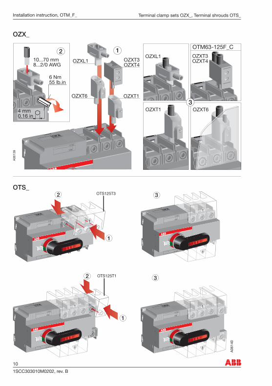
Installation instruction, OTM_F_ Terminal clamp sets OZX_, Terminal shrouds OTS_
OTS_
OZX_
II
A061
39
OZXL1
OZXT13
OZXT3OZXT4
OZXT1
OTM63-125F_C
OZXT6
OZXL112
OZXT3OZXT410...70 mm
8...2/0 AWG
OZXT6
4 mm0.16 in
6 Nm55 lb.in
OTS125T1
1
2
A061
40
3
3
2 OTS125T3
II
1
II
II II

111SCC303010M0202, rev. B
Installation instruction, OTM_F_Auxiliary contact blocks OA_, Handle storage OTVS0
OTVS0
OA_
11
37
21
13
A06
141
3
1 222x0,75...2,5 mm2x18...14 AWG
POZIDRIVEM3,5 Form 2
0,8 Nm7 lb.-in.
54
8,75
3623
OA2G11
1112
1314
I0
OA1G10 OA8G01max 2 NO NC
II
max 2OA1G10OA8G01OA2G11
OA2G11For 3-pole onlyII
A061
421
380
36
36
A B
2
20
50
15
II

1SCC303010M0202, rev. B12
Installation instruction, OTM_F_ Fourth pole OTP_
OTP_
OTM
II
(N)7 L4
(N)8 T4
OTPS125FP
N
N
OTPL125FP OTPN125FP OTPE125FP
N
N
PE
PE
N
N
I
O
N
N
N
N
21
OTP_OTPD60FPOTPD125FP
A061
43
2
OTM63-125OTM40 OTPS60FP OTPL60FP OTPN60FP OTPE60FP
OTM402,5...25 mm2
14...4 AWG2 x 2,5 -16 mm2
2 x 14...6 AWG
OTM63-12510...70 mm2 8...2/0 AWG
B
A
C
3
6 Nm55 lb.-in.
4 mm0.16 in
II
14-15 mm0.55-0.59 in

131SCC303010M0202, rev. B
Installation instruction, OTM_F_
Notes

1SCC303010M0202, rev. B14
Installation instruction, OTM_F_
Notes


Prin
ted
by: W
aasa
Gra
phics
Oy,
Vaas
a Fi
nlan
dPr
oduc
ted
by: G
RAFI
MER
, Vaa
sa, F
inlan
d
Breakers and SwitchesP.O Box 622FI-65101 VAASA, FinlandTelephone +358 10 22 11Telefax +358 10 22 45708www.abb.com
ABB Oy The technical data and dimensions are validat the time of printing. We reserve the right tosubsequent alterations.