motorola, the stylized m logo, and all other trademarks indicated … · computer software...
TRANSCRIPT


Motorola, the Stylized M Logo, and all other trademarks indicated as such herein are Trademarks of Motorola, Inc. Reg. U.S. Pat. & Tm. Off. © 2007 Motorola, Inc. All rights reserved. Printed in the U.S.A.

1 English
CO
NTEN
TS
tery . . . . . . . . . . . .11d Disposal . . . . . .12-Ion (Li-Ion) Battery . . . . . . . . . . . . . . . 13m-Ion (Li-Ion) Battery. . . . . . . . . .. . . . . . . 13 (optional accessory) .
. . . . . . . . . . . . . . 14ttery Pack . . . . . .14atteries. . . . . . . . .14tors and Drop-in Tray . . . . . . . . . . . . . . .15ion Belt Clip. . . . . .16ion . . . . . . . . . . . .16. . . . . . . . . . . . . . .17op-in Tray Single Unit . . . . . . . . . . . . . . .17one Battery . . . . . .18 Battery . . . . . . . .18In Charger’s Position tery . . . . . . . . . . . .19acity Battery . . . .20r LED Indicators . .21Time . . . . . . . . . . .22
CONTENTS
Contents . . . . . . . . . . . . . . . . . . . . . . . . . . 1
Computer Software Copyrights . . . . . . . 4
Safety . . . . . . . . . . . . . . . . . . . . . . . . . . . . 5
Product Safety and RF Exposure Compliance . . . . . . . . . . . . . . . . 5
Batteries and Chargers Safety Information6
Operational Safety Guidelines . . . . . . . . . . 7
Radio Overview . . . . . . . . . . . . . . . . . . . . 8
Parts of the radio . . . . . . . . . . . . . . . . . . . . 8ON/OFF/Volume Knob . . . . . . . . . . . . . 9Channel Selector Knob . . . . . . . . . . . . . 9Microphone . . . . . . . . . . . . . . . . . . . . . . 9Antenna. . . . . . . . . . . . . . . . . . . . . . . . . 9LED Indicator . . . . . . . . . . . . . . . . . . . . 9Side Buttons . . . . . . . . . . . . . . . . . . . . . 9The Lithium-Ion (Li-Ion) Battery . . . . . . 9
Batteries and Chargers . . . . . . . . . . . . . 11
Battery Features and Charging Options. . 11
About the Li-Ion BatBattery Recycling anInstalling the Lithium. . . . . . . . . . .. . . . . .Removing the Lithiu. . . . . . . . . . . . . . . . Alkaline battery pack. . . . . . .. . . . . . . . . .Installing Alkaline BaRemoving Alkaline BPower Supply, AdapCharger. . . . . . . . . .Installing Spring ActBattery Life InformatCharging the BatteryCharging with the DrCharger. . . . . . . . . .Charging a Stand-alCharging a StandardIdentifying the Drop-Before Charging BatCharging a High CapDrop-in Tray ChargeEstimated Charging

En
CO
NTE
NTS
he Values The Radio . . . . . . . . . . . . . . .32s Values . . . . . . . .35 . . . . . . . . . . . . . . .36 . . . . . . . . . . . . . . .36L Values . . . . . . . .36Values . . . . . . . . .37encies, Codes and . . . . . . . . . . . . . . .37
. . . . . . . . . . . . . . .37FAQ . . . . . . . . . . .38ample . . . . . . . . . .39ming a Frequency 39 . . . . . . . . . . . . . . .41 . . . . . . . . . . . . . . .42elete. . . . . . . . . . .42mming Software) .43 . . . . . . . . . . . . . . .44 . . . . . . . . . . . . . . .44. . . . . . . . . . . . . . .44 . . . . . . . . . . . . . . .44 . . . . . . . . . . . . . . .44 . . . . . . . . . . . . . . .45
2glish
Charging a Radio and Battery Using a Multi-Unit Charger-MUC (Optional Accessory) . . . . . . . . . . . . . . . . . . . . . . . . . . . . . . . 23
Getting Started . . . . . . . . . . . . . . . . . . . . 24
Turning radio ON/OFF . . . . . . . . . . . . . . . 24Adjusting volume . . . . . . . . . . . . . . . . . . . 24Selecting a Channel . . . . . . . . . . . . . . . . . 24Talking and Monitoring. . . . . . . . . . . . . . . 24Receiving a Call . . . . . . . . . . . . . . . . . . . . 25Talk Range. . . . . . . . . . . . . . . . . . . . . . . . 25Radio LED Indicators . . . . . . . . . . . . . . . 27Hands-Free Use/VOX . . . . . . . . . . . . . . . 29
With Compatible VOX Accessories. . . 29Hands Free without Accessories (iVOX)30Setting VOX Sensitivity . . . . . . . . . . . . 30Microphone Gain. . . . . . . . . . . . . . . . . 30Battery Save . . . . . . . . . . . . . . . . . . . . 30Reset To Factory Defaults . . . . . . . . . 31End of Transmission Tone (Roger Beep Tone). . . . . . . . . . . . . . . . . . . . . . . . . . 31
Programming Features . . . . . . . . . . . . . 32
Programming Mode. . . . . . . . . . . . . . . 32
Learning To Read TSignals You . . . . . .Reading Frequencie . . . . . . . . . . . . . . . . . . . . . . . . . . . . . . . .Reading CTCSS/DPReading Auto-Scan Programming FrequAuto-Scan. . . . . . . . Saving Settings. . . .Programming Mode
Programming values exExample of Program
Scan . . . . . . . . . . . . . .Editing Scan List. . .Nuisance Channel D
CPS (Computer PrograBandwidth Select . .Time-Out Timer . . .Battery Type SettingCall Tones . . . . . . .Scramble . . . . . . . .
Cloning Radios . . . . . .

3 English
CO
NTEN
TS
When ordering the MUC . . . . . . . . . . . 46What to do if cloning fails . . . . . . . . . . 48Cloning using the CPS (Computer Programming Software) . . . . . . . . . . . 48
Troubleshooting. . . . . . . . . . . . . . . . . . . 49
Use and Care . . . . . . . . . . . . . . . . . . . . . 52
Frequency and Code Charts . . . . . . . . . 53
Motorola Limited Warranty For The United States and Canada . . . . . . . . . . . . . . . . . 57
What Does this Warranty Cover?. . . . . . . 57Products and Accessories. . . . . . . . . . 57Exclusions . . . . . . . . . . . . . . . . . . . . . . 58Exclusions . . . . . . . . . . . . . . . . . . . . . . 59
Export Law Assurances . . . . . . . . . . . . . . 60
Accessories . . . . . . . . . . . . . . . . . . . . . . 61
Audio Accessories . . . . . . . . . . . . . . . . . . 61Battery . . . . . . . . . . . . . . . . . . . . . . . . . . . 61Carry Accessories . . . . . . . . . . . . . . . . . . 61Software Applications. . . . . . . . . . . . . . . . 61Cables . . . . . . . . . . . . . . . . . . . . . . . . . . . 61Chargers . . . . . . . . . . . . . . . . . . . . . . . . . 62

CO
MPU
TER
SO
FTW
AR
E C
OPY
RIG
HTS
4English
The Motorola products described in this manual may include copyrighted Motorola computer programs stored in semiconductor memories or other media. Laws in the United States and other countries preserve for Motorola certain exclusive rights for copyrighted computer programs, including, but not limited to, the exclusive right to copy or reproduce in any form the copyrighted computer program. Accordingly, any copyrighted Motorola computer programs contained in the Motorola products described in this manual may not be copied, reproduced, modified, reverse-engineered, or distributed in any manner without the express written permission of Motorola.
Furthermore, the purchase of Motorola products shall not be deemed to grant either directly or by implication, estoppel, or otherwise, any license under the copyrights, patents or patent applications of Motorola, except for the normal non-exclusive license to use that arises by operation of law in the sale of a product.
COMPUTER SOFTWARE COPYRIGHTS

5 English
SAFETY
SAFETY
PRODUCT SAFETY AND RF EXPOSURE COMPLIANCE
ATTENTION!This radio is restricted to occupational use only to satisfy FCC RF energy exposure requirements.
For a list of Motorola-approved antennas, batteries, and other accessories, visit the following website which lists approved accessories:
http://www.motorola.com/XTNiBefore using this product, read the operating instructions and RF energy awareness information contained in the Product Safety and RF Exposure booklet enclosed with your radio.
!C a u t i o n

BA
TTER
IES
AN
D C
HA
RG
ERS
age to the electric plug plug rather than the cord he charger.
ould not be used unless . Use of an improper result in risk of fire and xtension cord must be the cord size is 18AWG eet (2.0 m), and 16AWG eet (3.0 m).
electric shock, or injury, arger if it has been broken ay. Take it to a qualified esentative.
he charger; it is not ement parts are not ly of the charger may cal shock or fire.
tric shock, unplug the outlet before attempting leaning
SAFE
TY IN
FOR
MA
TIO
N
6English
BATTERIES AND CHARGERS SAFETY INFORMATION
This document contains important safety and operating instructions. Read these instructions carefully and save them for future reference. Before using the battery charger, read all the instructions and cautionary markings on
• the charger,
• the battery, and
• the radio using the battery.
1. To reduce risk of injury, charge only the rechargeable Motorola-authorized batteries. Other batteries may explode, causing personal injury and damage.
2. Use of accessories not recommended by Motorola may result in risk of fire, electric shock, or injury.
3. To reduce risk of damand cord, pull by the when disconnecting t
4. An extension cord shabsolutely necessaryextension cord could electric shock. If an eused, make sure thatfor lengths up to 6.5 ffor lengths up to 9.8 f
5. To reduce risk of fire,do not operate the chor damaged in any wMotorola service repr
6. Do not disassemble trepairable and replacavailable. Disassembresult in risk of electri
7. To reduce risk of eleccharger from the AC any maintenance or c

BA
TTERIES A
ND
CH
AR
GER
S SA
FETY INFO
RM
ATIO
N
7 English
perature around the nt must not exceed 40°C
ocated where it will not be er, or subjected to water,
OPERATIONAL SAFETY GUIDELINES • Turn the radio OFF when charging battery.
• The charger is not suitable for outdoor use. Use only in dry locations/conditions.
• Connect charger only to an appropriately fused and wired supply of the correct voltage (as specified on the product).
• Disconnect charger from line voltage by removing main plug.
• The outlet to which this equipment is connected should be nearby and easily accessible.
• Maximum ambient tempower supply equipme(104°F).
• Make sure the cord is lstepped on, tripped ovdamage, or stress.

8English
RA
DIO
OVE
RVI
EW
RADIO OVERVIEW
Antenna
Microphone
Channel Selector Knob
ON/OFF/Volume
LED Indicator
Model Label
PTT (Push-to-Talk) Button
SB1 - Monitor Button
SB2 - Scan/Nuisance Channel Delete
Lithium-Ion Battery
PARTS OF THE RADIO

9 English
RA
DIO
OVER
VIEW
ON/OFF/Volume Knob
Used to turn the radio ON or OFF and to adjust the radio’s volume.
Channel Selector Knob
Used to switch the radio to different channels.
Microphone
Speaks clearly into the microphone when sending a message.
Antenna
The radio's antenna is non-removable.
LED Indicator
Used to give battery status, power-up status, radio call information and scan status
Side Buttons
• Push-to-Talk (PTT) Button
Press and hold down this button to talk, release it to listen.
• Side Button 1 (SB1)
The Side Button 1 is a general button that can be configured by the Computer Programming Software - CPS. The default setting of SB1 button is ‘Monitor’.
• Side Button 2 (SB2)
The Side Button 2 is a general button that can be configured by the CPS. The SB2 default setting is ‘Scan/Nuisance Channel Delete’.
The Lithium-Ion (Li-Ion) Battery
XTNi™ Series provides different types of batteries. For more information, see ‘Battery Features and Charging Options’ on page 11.

10English
RA
DIO
OVE
RVI
EW
This User Guide covers multiple XTNi™ Series models, and may detail some features your radio does not have. The model number of the radio is shown on the front of the radio,
underneath the speaker, and tells you the following information:
Model Frequency Band
Transmit Power (Watts)
Number of Channels Antenna
XTNi PMR446 0.5 8 Non-removable

BA
TTERIES A
ND
C
HA
RG
ERS
11 English
cycles than a battery overcharge and is day. Further, a battery overcharging and harge, lasts even
esigned specifically to charger and vice Motorola equipment age and void the ttery should be at temperature),
rging a cold battery y result in leakage of
ly in failure of the battery (above 95°F d discharge capacity,
ce of the radio. ery chargers contain a cuit to ensure that ithin the temperature
BATTERIES AND CHARGERSXTNi™ Series radios provide Lithium-Ion (Li-Ion) batteries that comes in different capacities that will define the battery life. It also offers the option to use Alkaline batteries.The radio comes equipped with a rapid charger.
BATTERY FEATURES AND CHARGING OPTIONS
About the Li-Ion Battery
The XTNi™ radio series come equipped with a rechargeable Li-Ion battery. This battery should be charged before initial use to ensure optimum capacity and performance. Battery life is determined by several factors. Among the more critical are the regular overcharge of batteries and the average depth of discharge with each cycle. Typically, the greater the overcharge and the deeper the average discharge, the fewer cycles a battery will last. For example, a battery which is overcharged and discharged 100% several
times a day, lasts fewerthat receives less of an discharged to 50% per which receives minimalaverages only 25% disclonger.Motorola batteries are dbe used with a Motorolaversa. Charging in non-may lead to battery dambattery warranty. The baabout 77°F (25°C) (roomwhenever possible. Cha(below 50° F [10°C]) maelectrolyte and ultimatebattery. Charging a hot [35°C]) results in reduceaffecting the performanMotorola rapid-rate batttemperature-sensing cirbatteries are charged wlimits stated above.
BA
TTER
IES
AN
D ers participate in this
n of the drop-off facility BRC's Internet web
call 1-800-8- site and telephone ther useful information tions for consumers, mental agencies.
12English
CH
AR
GER
SBattery Recycling and Disposal
Li-Ion rechargeable batteries can be recycled. However, recycling facilities may not be available in all areas. Under various U.S. state laws and the laws of several other countries, batteries must be recycled and cannot be disposed of in landfills or incinerators. Contact your local waste management agency for specific requirements and information in your area. Motorola fully endorses and encourages the recycling of Li-Ion batteries. In the U.S. and Canada, Motorola participates in the nationwide Rechargeable Battery Recycling Corporation (RBRC) program for Li-Ion battery collection and recycling.
Many retailers and dealprogram. For the locatioclosest to you, access Rsite at www.rbrc.com orBATTERY. This internetnumber also provides oconcerning recycling opbusinesses and govern

BA
TTERIES A
ND
C
HA
RG
ERS
13 English
-Ion (Li-Ion) Battery
latch and hold it depressed tery.
rom the radio.
battery latch
Installing the Lithium-Ion (Li-Ion) Battery
1. Turn OFF the radio.
2. With the Motorola logo side up on the battery pack, fit the tabs at the bottom of the battery into the slots at the bottom of the radio’s body.
3. Press the top part of the battery towards the radio until a click is heard.
Note: To learn about the Li-Ion Battery Life features, refer to ‘About the Li-Ion Battery’ on page 11.
Removing the Lithium
1. Turn OFF the radio.
2. Push down the batterywhile removing the bat
3. Pull the battery away f
slots
battery latch

BA
TTER
IES
AN
D tteries
it is turned on.s, on both sides of the
ry away from the radio’s ry from the radio’s body.
Alkaline Battery Door
14English
CH
AR
GER
SAlkaline battery pack (optional accessory)
Installing Alkaline Battery Pack
1. Turn OFF the radio, if it is turned on.2. Remove Li-Ion battery
3. Assemble alkaline battery pack (optional accessory) in the same steps as installing the Li-Ion battery pack.
4. Remove battery door from alkaline battery pack.5. Slide the 5 AA alkaline batteries into the frame,
matching the markings inside the compartment.
Removing Alkaline Ba
1. Turn OFF the radio, if2. Slide the battery latche
battery, downwards.3. Pull the top of the batte
body, and lift the batte
Alkaline Battery Door

BA
TTERIES A
ND
C
HA
RG
ERS
15 English
r grooves into the power o place.
rd to remove.
in the pictures are just oses. The adaptor you be different.
Remove
Adaptor
Power Supply
Power Supply, Adaptors and Drop-in Tray Charger
Your radio comes with one Drop-in Tray Charger, one Power Supply (also known as Transformer) and a set of adaptors.Your power supply, has a ‘switchable’ capability which allows to suit any of the adaptors that comes with your radio package. The adaptor you should choose to install depends on the region you're located.Once you have identified the adaptor that matches your electrical outlet, proceed to install it as follows:
• Slide down the adaptosupply until it snaps int
• Slide the adaptor upwa
Note: The adaptor shownfor illustration purpshould install may
Drop-in Tray Charger
Power Supply
Install
Power Supply
Adaptor

BA
TTER
IES
AN
D n
model and/or region be different. This e estimated battery ave feature is ON battery life will be art summarizes battery
with Battery Save e ON
0.5 Watt
16 hours
32 hours
s estimated based mit/ 5% receive/ y standard duty
16English
CH
AR
GER
SInstalling Spring Action Belt Clip
1. Slide the spring action belt clip rails into the belt clip grooves on the back of the battery pack and slide it down until the belt clip tab snaps into place.
2. To remove, pull back the metal release tab on the belt clip tab and push the spring action belt clip upward to remove.
Battery Life Informatio
Li-Ion Battery Life
Depending on the radiothe battery capacity willfeature will determine thlife. When the Battery S(enabled by default) thelonger. The following chlife estimations:
belt clip tab
spring action belt clip
Li-Ion Battery Life featur
Battery
Standard
High Capacity
Note: Battery life ion 5% trans90% standbcycle.

BA
TTERIES A
ND
C
HA
RG
ERS
17 English
ith the radio attached), proved Drop-in Tray rop-in Tray Multi-Unit
p-in Tray Single Unit
charger on a flat surface.
the power supply into the drop-in tray charger.
to a power outlet. tray with the front of the
Power Supply(Transformer)
ray Charger
Alkaline Battery Life
The following chart provides estimations about the Battery Life using the Alkaline Batteries:
Charging the Battery
To charge the battery (wplace it in a Motorola-apSingle Unit Charger or DCharger.
Charging with the DroCharger
1. Place the drop-in tray
2. Insert the connector ofport on the side of the
3. Plug the AC adaptor in4. Insert the radio into the
Alkaline Battery Life
Battery Save Feature 0.5 Watt
ON 37 hours
Note: Battery life are being estimated based on 5% transmit/ 5% receive/ 90% standby standard duty cycle.
Drop-in TDrop-in TrayCharger Port
BA
TTER
IES
AN
D
e bracket in the charger is correct position for
d or High-capacity harging a Standard
ge 18.
attery
r has a removable le depending on the s to be charged. It is
er the battery (with the attery. The drop-in tray lt set up to charge a llowing image on page ntation for each battery:
18English
CH
AR
GER
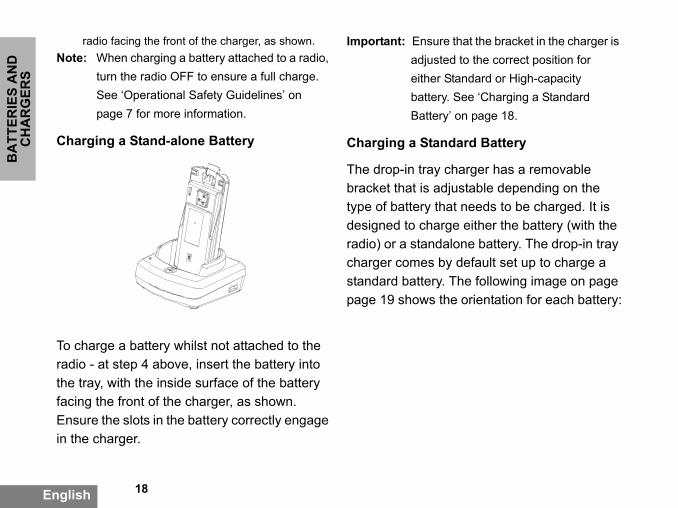
Sradio facing the front of the charger, as shown.
Note: When charging a battery attached to a radio, turn the radio OFF to ensure a full charge. See ‘Operational Safety Guidelines’ on page 7 for more information.
Charging a Stand-alone Battery
To charge a battery whilst not attached to the radio - at step 4 above, insert the battery into the tray, with the inside surface of the battery facing the front of the charger, as shown. Ensure the slots in the battery correctly engage in the charger.
Important: Ensure that thadjusted to theeither Standarbattery. See ‘CBattery’ on pa
Charging a Standard B
The drop-in tray chargebracket that is adjustabtype of battery that needdesigned to charge eithradio) or a standalone bcharger comes by defaustandard battery. The fopage 19 shows the orie

BA
TTERIES A
ND
C
HA
RG
ERS
19 English
pacity
e bracket
Identifying the Drop-In Charger’s Position Before Charging Battery
Adjustable bracket
Standard High and Ultra High Ca
Adjustabl

BA
TTER
IES
AN
D
re to return position back to attery. Label on the uld show ‘Standard
cket is assembled tandalone battery and to be properly charged.
dle
20English
CH
AR
GER
SCharging a High Capacity Battery
To convert the charger from the default setup to accommodate the high capacity:
1. Squeeze both tabs on each side of the removable bracket in the drop-in charger tray carefully and lift the bracket from the charger tray.
2. Rotate the removable bracket 180 degrees and replace it by fitting it in the charger slot until it clicks. The label on the removable bracket should show ‘High & Ultra Capacity Battery’ facing front of the charger.
3. Repeat same proceducharging a Standard Bremovable bracket shoBattery’ facing front.
Note: Make sure the bracorrectly for both sbattery (with radio)
RemovablePiece
RemovablePiece
Turn arounhorizonta
180 degre

BA
TTERIES A
ND
C
HA
RG
ERS
21 English
ted
Drop-in Tray Charger LED Indicators
Standard Charger LED Indicator
Status LED Status Comments
Power ON Steady red indication for 3 seconds The charger has powered up
Charging Blinking red (slow) The charger is currently charging
Charging Complete Steady red indication Battery is fully charged
Battery Fault(*) Blinking red (fast) Battery had a fault when battery was inserted
Notes:• (*) Normally re-seating the battery pack will correct this issue. • (**) Battery temperature is too warm or too cold or wrong power supply is being used
Rapid Charger LED Indicator
Status LED Status Comments
Power ON Steady green indication for 3 seconds The charger has powered up
Charging Blinking green The charger is currently charging
Top-off Charging Blinking green (slow) Battery is near fully charged
Charge Complete Steady green indication Battery is fully charged
Battery Fault (*) Blinking red (fast) Battery has a fault when battery was inser
Waiting to Charge (**) Double-blink yellow indications Battery charging conditions not suitable
Notes:• (*) Normally re-seating the battery pack will correct this issue. • (**) Battery temperature is too warm or too cold or wrong power supply is being used
BA
TTER
IES
AN
D
22English
CH
AR
GER
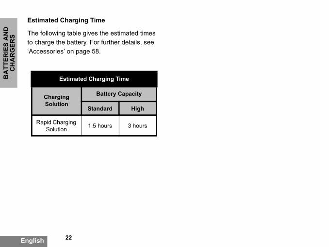
SEstimated Charging Time
The following table gives the estimated times to charge the battery. For further details, see ‘Accessories’ on page 58.
Estimated Charging Time
Charging Solution
Battery Capacity
Standard High
Rapid Charging Solution 1.5 hours 3 hours
BA
TTERIES A
ND
C
HA
RG
ERS
23 English
ry into the charging
will also allow you to clone radios and 3 Target
does not need to be urce, but all radios require er details on MUC’s in the Instructions Sheet Refer to the “Accessories” rt number for ordering the
Indicators Comments
d The charger is currently charging
en
Battery is fully charged
Battery had a fault when battery was
inserted
ery pack will correct this
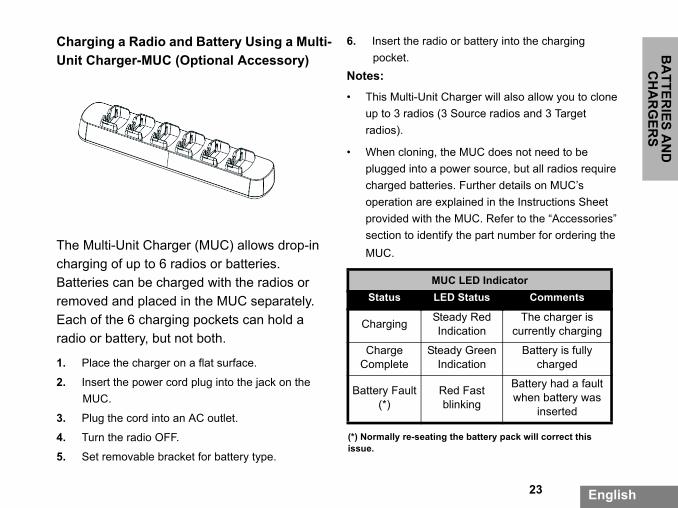
Charging a Radio and Battery Using a Multi-Unit Charger-MUC (Optional Accessory)
The Multi-Unit Charger (MUC) allows drop-in charging of up to 6 radios or batteries. Batteries can be charged with the radios or removed and placed in the MUC separately. Each of the 6 charging pockets can hold a radio or battery, but not both.
1. Place the charger on a flat surface.
2. Insert the power cord plug into the jack on the MUC.
3. Plug the cord into an AC outlet.
4. Turn the radio OFF.
5. Set removable bracket for battery type.
6. Insert the radio or battepocket.
Notes:
• This Multi-Unit Charger up to 3 radios (3 Sourceradios).
• When cloning, the MUCplugged into a power socharged batteries. Furthoperation are explainedprovided with the MUC.section to identify the paMUC.
MUC LED Status LED Statu
Charging Steady ReIndication
Charge Complete
Steady GreIndication
Battery Fault (*)
Red Fastblinking
(*) Normally re-seating the battissue.

GET
TIN
G S
TAR
TED
EL
ate the Channel ct the desired channel
separately. Each quency, Interference an Settings.
ORING
r for traffic before lking over’ someone ingold the SB1(*) button cess channel traffic. If u will hear ‘static’. To
in. Once channel traffic th your call by pressing ransmitting, the radio 3 seconds. not been programmed for
24
English
English
GETTING STARTEDFor the following explanations, refer to page 8 of the user guide.
TURNING RADIO ON/OFF
To turn ON the radio, rotate the ON/OFF/Volume Knob clockwise. The radio will chirp and the LED will briefly blink red.To turn the radio OFF, rotate the ON/OFF/Volume Knob counterclockwise until you hear a ‘click’ and the radio LED indicator turns OFF.
ADJUSTING VOLUME
Turn the ON/OFF/Volume Knob clockwise to increase the volume, or counterclockwise to decrease the volume.
Note: Do not hold the radio too close to the ear when it is at a high volume setting or when adjusting the volume setting.
SELECTING A CHANN
To select a channel, rotSelector Knob and selenumber. Program each channel channel has its own FreEliminator Code and Sc
TALKING AND MONIT
It is important to monitotransmitting to avoid ‘tawho is already transmittTo monitor, press and hfor 2 to 3 seconds to acno activity is present, yorelease, press SB1 agahas cleared, proceed withe PTT button. When tLED will blink red every(*) This assumes SB1 hasa different mode.

25English
GETTIN
G STA
RTED
designed to maximize ve transmission range ended that you do not an 1.5 meters apart, to
the terrain. It will be uctures, heavy foliage indoors or in
flat, open areas with verage. Medium range nd trees are in the
urs when dense foliage the communication
o-way communication, and interference e the same on both the stored profile that
ed on the radio:
RECEIVING A CALL
1. Select a channel by rotating the Channel Selector Knob until you reach the desired channel.
2. Make sure the PTT button is released and listen for voice activity.
3. The LED indicator blinks RED while the radio is receiving a call.
4. To respond, hold the radio vertically 1 to 2 inches (2.5 to 5cm) from mouth. Press the PTT button to talk; release it to listen.
Note: Please notice that when radio is receiving or transmitting, LED is always RED.
Note: In order to listen to all activity on a current channel, short press the SB1 to set the CTCSS/DPL code to 0. This feature is called CTCSS/DPL Defeat (Squelch set to SILENT).
TALK RANGE
XTNi radios have been performance and improin the field. It is recommuse the radios closer thavoid interference.Talk range depends on affected by concrete strand by operating radiosvehicles. Optimal range occurs inup to 9 kilometres of cooccurs when buildings away. Minimal range occand mountains obstructpath.To establish a proper twthe channel, frequency,eliminator codes must bradios. This depends onhas been preprogramm

GET
TIN
G S
TAR
TED
t up frequencies and e channels, refer to
n page 31.
ator Codes are referred L codes or PL/DPL codes
26
English
English
1. Channel: Current channel that the radio is using, depending upon radio model.
2. Frequency: The frequency the radio uses to transmit/receive.
3. Interference Eliminator Code: These codes help minimize interference by providing a choice of code combinations.
4. Scramble Code: Codes that make the transmissions sound garbled to anyone listening who is not set to that specific code.
5. Bandwidth: Some frequencies have selectable channel spacing, which must match other radios for optimum audio quality.
For details of how to seCTCSS/DPL codes in th“Programming Mode” o
Note: Interference Eliminalso as CTCSS/DP

27English
GETTIN
G STA
RTED
RADIO LED INDICATORS
RADIO STATUS LED INDICATION
Channel Alias Edit Red heartbeat
Channel Busy Solid orange
Cloning Mode Two orange heartbeats
Cloning In Progress Solid orange
Fatal Error at Power up One green blink, one orange blink, one green blink, then repeat for 4 seconds
Low Battery Orange blink
Low Battery Shutdown Orange heartbeat
Monitor LED is OFF
Power-Up Solid red for 2 seconds
‘Idle’ Programming Mode / Channel Mode Green heartbeat
Scan Mode Red heartbeat)
Transmit (Tx)/Receive (RX) Red heartbeat
Note: Channel Alias Edit only applies to Display Models

GET
TIN
G S
TAR
TED
Programming the VOX level is set to . Then, perform the
r.
ccessory firmly into
LED will blink double red
EFORE placing
o accessory microphone alking.
rily disabled by pressing removing the audio
es, contact your Motorola
28
English
English
HANDS-FREE USE/VOX
Motorola XTNi™ radios can operate hands-free (VOX) when used with compatible VOX accessories. A short delay occurs between talking and the radio transmission.
With Compatible VOX Accessories
The default factory setting for VOX sensitivity level is OFF (level ‘0’). Before using VOX,
usethe CPS (ComputerSoftware) to make surea level different from "0"following steps:
1. Turn radio OFF.
2. Open accessory cove
3. Insert plug of audio aaccessory port.
4. Turn radio ON. Radio
5. Lower radio volume Baccessory near ear.
6. To transmit, speak intand to receive, stop t
7. VOX can be temporathe PTT button or by accessory.
Note: To order accessoridealer.
29English
GETTIN
G STA
RTED
vel 0). If you want VOX level should be om 0.
dio's microphone can nt users or operating
sted only through the lt setting is set to level
tends battery life as ’ state each time there
nable/disable press multaneously for 2 or 3
Hands Free without Accessories (iVOX)
• Enable iVOX by pressing the PTT button while turning the radio ON.
• iVOX operation can be temporarily disabled by pressing PTT.
• A short press of the PTT button will re-enable iVOX.
There is a short delay between when talking and the radio transmission.
Note: The iVOX feature is only available on XTNId (Display model).
Setting VOX Sensitivity
The sensitivity of the radio's accessory or microphone can be adjusted during VOX operation to suit different operating environments. VOX/iVOX sensitivity can be programmed via the CPS.
Default value is OFF (letouse the VOX feature, set at a level different fr
1 = Low sensitivity
2 = Medium sensitivity
3 = High sensitivity
Microphone Gain
The sensitivity of the rabe adjusted to fit differeenvironments.
This feature can be adjuCPS. Microphone defau2 (Medium gain).
Battery Save
Battery Save feature exyour radio goes into ‘Idleis no radio activity. To eSB1 and SB2 buttons si

GET
TIN
G S
TAR
TED
30
English
English
seconds while powering up the radio until you hear a quick series of beeps. To have a slightly better attack time, set Battery Save feature to OFF so that the radio is always ready to transmit or receive without any delays.Note: Battery Save feature is set to ON by default
Reset To Factory Defaults
Reset To Factory Defaults will set back all radio features to the original factory default settings. To do so press PTT, SB2 and SB1 simultaneously while turning ON the radio until you hear a high tone chirp beep.
End of Transmission Tone (Roger Beep Tone)
Short press the SB1 button while turning ON the radio to enable/disable End of Transmission Tone.
Note: By default, this feature is OFF.

31 English
PRO
GR
AM
MIN
G
FEATU
RES
d unwanted
allows you to set a omatically enable scan that channel ( you will utton to start scanning).
Values The Radio
el does not have a es that are being will communicate this and LED indications. ink two colors: 'orange' other values from '1' to links differentiate the io is showing you. umber, it will generate nd long beeps.
PROGRAMMING FEATURES
To easily program all the features in your radio, it is recommended to use the CPS Kit which includes the Programming Cable, CPS and accessories sections.
Programming Mode
Programming Mode is special radio mode that allows you to program basic radio's features by using the radio’s panel programming. When the radio is set to Programming Mode, you are able to read and modify three features:• Frequencies,• Codes (CTCSS/DPL) and,• Auto-scan.The Programming Frequencies feature allows you to select frequencies for each channel.
The Interference Eliminator Code (CTCSS/ DPL) helps minimize interference by providing you with a choice of code combinations that
filter out static, noise, anmessages.
The Auto Scan feature particular channel to auteach time you switch tonot need to press any b
Learning To Read TheSignals You
As the non-display moddisplay to show the valuprogrammed, the radio information using beepsThe radio's LEDs will blto signal '0' and red for '9'. Short and long red bspecific number the radAs the radio blinks the na combination of short a
English
PRO
GR
AM
MIN
G
ures Values
ation
red blinksed blinkst red blinksred blinks
32
FEA
TUR
ES
English
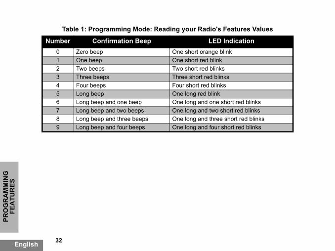
Table 1: Programming Mode: Reading your Radio's Feat
Number Confirmation Beep LED Indic0 Zero beep One short orange blink1 One beep One short red blink2 Two beeps Two short red blinks3 Three beeps Three short red blinks4 Four beeps Four short red blinks5 Long beep One long red blink6 Long beep and one beep One long and one short 7 Long beep and two beeps One long and two short r8 Long beep and three beeps One long and three shor9 Long beep and four beeps One long and four short

33 English
PRO
GR
AM
MIN
G
FEATU
RES
PROGRAMMING MODE1 2
3 PTT
PTTPTTPTT
LongPTT
LongPTT
LongPTT
Exit
“Roll Over”key chirp
PTT
PTT
Enter Programming Mode
(PTT + SB1 + Turn ON radio)
PTT
SecondDigit
ThirdDigit
ON/OFF
Auto-Scan
CTCSS/DPLFrequencies
IdleProgramming
Mode
FirstDigit
FirstDigit
SecondDigit
Figure 1 Entering Programming Mode
English
PRO
GR
AM
MIN
G
Entering Programming Mode Once you are in the 'Idle' Programming Mode, the radio frequencies, etting by short pressing e along the different s.
Values
cies values you need to i™ series radios have HF (refer to UHF
ming Mode, the radio e it was programmed the PTT button (see lue corresponds to the alue. If you short press the radio will signal you
34
FEA
TUR
ES
English
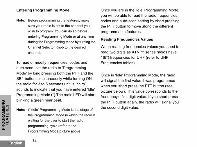
Note: Before programming the features, make sure your radio is set to the channel you wish to program. You can do so before entering Programming Mode or at any time during the Programming Mode by turning the Channel Selector Knob to the desired channel.
To read or modify frequencies, codes and auto-scan, set the radio to 'Programming Mode' by long pressing both the PTT and the SB1 button simultaneously while turning ON the radio for 3 to 5 seconds until a ‘chirp’ sounds to indicate that you have entered 'Idle' Programming Mode (*).The radio LED will start blinking a green heartbeat.
Note: (*)'Idle' Programming Mode is the stage of the Programming Mode in which the radio is waiting for the user to start the radio programming cycle (refer to the Programming Mode picture above).
you will be able to readcodes and auto-scan sthe PTT button to movprogrammable feature
Reading Frequencies
When reading frequenread two digits as XTN16(*) frequencies for UFrequencies tables).
Once in ‘Idle’ Programwill signal the first valuwhen you short press picture below). This vafrequency's first digit vthe PTT button again, the second digit value.

35 English
PRO
GR
AM
MIN
G
FEATU
RES
ple of the order in signaling the ‘118’
utton. The radio will ‘1’, short press PTT dio will show the lly, short press PTT w the third digit ‘8’.
ThirdDigit
Digit
program values
8
Reading CTCSS/DPL ValuesIf you continue short pressing the PTT button, as shown in the ”Entering Programming Mode” on page 33 (Stage 2) the radio will move forward to programming CTCSS/PL Codes.When reading the values for CTCSS/PL Codes the radio signals you the digit codes each time you short press the PTT button. You will have to read three digits as XTNi Series™ have up to 122 codes available (refer to ‘Frequencies and Codes Charts’ Section).The following is an examwhich your radio will beCTCSS/DPL code::
• Short press the PTT bsignal you the first digit button again and the rasecond digit ‘1’ and finaagain and radio will sho
1
PTTPTT
Frequencies
FirstDigit
SecondDigit
FirstDigit
Second
Example of how to
1 1

English
PRO
GR
AM
MIN
G
Reading Auto-Scan Values Programming Frequencies, Codes and
ignals and beeps, you t setting value by either ressing SB1 or pressing SB2. The radio setting it has been
the new setting, you
ntinue programming,ve and return to 'Idle' rutton twice to exit 'Idle' d return to the normal
36
FEA
TUR
ES
English
After finishing reading CTCSS/DPL codes, if you short press PTT once again, the radio will take you to Auto-Scan (”Entering Programming Mode” on page 33 (stage 3) Auto-Scan only has two values:
Note that while in Auto-Scan Mode, if you shortpress PTT button, the radio will return to the ‘Idle’ Programming Mode. It will then generate a ‘roll-over’ chirp and it will start blinking a green heartbeat.
Auto-Scan
Each time your radio scan change the currenincreasing it by short pdecreasing it by short will then signal the newprogrammed to.
Saving Settings
If you are satisfied withcan either:• short press PTT to co• long press PTT to saProgramming Mode, o• long press the PTT bProgramming Mode anradio operation.
If the radio signals the value...
It means Auto-Scan is....
0 OFF
1 ON
Note: AutoScan is set to OFF by default.

37 English
PRO
GR
AM
MIN
G
FEATU
RES
d enter Programming tions in the beginning
am a frequency (or dio would not do it. It e back to value ‘0’.
you to program any lable in the frequencies mple, if you try to
radio would not accept e allowed is 122. Same equencies. Check the Charts section to ramming a valid
the Programming uld not do it.ed using the CPS for l Programming. To
Notes: • If you don't want to save the value you just programmed, turn radio OFF or change channel using the channel knob.
• If you ‘roll-over’ to the beginning at Idle Programming Mode you will hear a ‘chirp’ and radio LED will start blinking green again. All values that were changed will be automatically saved.
Programming Mode FAQ
1. I got distracted while programming and forgot which digit I was programming. What should I do?Return to 'Idle' Programming Mode and start over, as you will not be able to go back into the Programming Mode (the radio does not provide further way to let you know the specific stage you are when programming). Therefore you can:• Long press the PTT button. The radio will return to the 'Idle' Programming Mode or,
• Turn OFF the radio anMode again (see instrucof this section)2. I am trying to progrcode) value but the rarolled over and took mThe radio will not allow values that are not avaiand codes pool. For exaprogram code 128, the it, as the maximum valuthing will happen with frFrequencies and Codesmake sure you are prognumber.3. I am trying to enter Mode but the radio woThe radio might be locknot allowing Front-Panereenable, use the CPS.

English
PRO
GR
AM
MIN
G
4. When I was programming I made a 6. I am done programming the features in t to program another
nel you wish to program elector Knob. The radio Programming Mode. If hanges, make sure you mming Mode before as otherwise you will
UES EXAMPLE
ing a Frequency
uency value is set up to F default frequency ‘02’ 5 Mhz), and you want to Number = ‘13’ (which is hz), follow this
ode
38
FEA
TUR
ES
English
mistake and program the wrong value. How can I erase it or re-program it?If you make a mistake while programming a value you have two choices:a) The radio roll-over (and generates a 'wrap-around' sound) each time it reaches a maximum (9) or minimum (0) value. Keep increasing (short press SB1) or decreasing (short pressing SB2) until you get the desired value or,b) Turn OFF the radio and start-over.
5. I just programmed the value I wanted. How do I exit Programming Mode?• If you are in Programming Mode you can exit by long pressing the PTT button twice.• If you are already in the ‘Idle’ Programming Mode, long press the PTT button once.
this channel and wanchannel.Switch to the new chanby using the Channel Swill go into to the 'Idle' you wish to save the care in the ‘Idle’ Prograswitching the channel lose changes made.
PROGRAMMING VAL
Example of Programm
Assuming current freqchannel 1, with the UH(equivalent to 446.0187change it to Frequencymapped to 446.05625 Msequence:• Enter Programming M

39 English
PRO
GR
AM
MIN
G
FEATU
RES
tton three times (Enter ing Selection Mode). nge to indicate that ss the SB1 button once 1’) LED indicator will e PTT button (to move cond digit). Radio LED ate current value is ‘0’.utton and move ahead it. LED indicator will rent value is ‘1’.to change the ‘third 1 button to change
‘3’. Radio will signal the
tton to save changes ramming Mode.ming Mode, LED g a green heartbeat.tton to exit
• Short press the PTT button to enter Frequency Mode. Radio will signal current value ‘0’ (orange blink)• Press the SB1 button once to increase first digit to ‘1’.• Short press the PTT button once to move ahead and program the frequency’s second digit. Radio will signal current value which is ‘2’ (two red blinks).• Press the SB1 button to increase the digit value to ‘3’.• Long press the PTT button. LED indicator will show a green heartbeat to indicate 'Idle' state. • Long press the PTT button to exit Programming Mode or turn radio OFF.Example of Programming a CodeAssuming current code value is set to factory default ‘001’, and you want to change it to CTCSS/DPL Code = 103 follow the sequence below:• Enter Programming Mode
• Short press the PTT buCTCSS/DPL ProgrammRadio LED will blink oracurrent value is ‘0’ • Pre(to change first digit to ‘blink red. Short press thforward and program sewill blink orange to indic• Short press the PTT bto program the third digblink red to indicate cur• Press the SB1 button digit’ to ‘2’. Press the SBagain this ‘third digit’ to chosen value.• Long press the PTT buand return to 'Idle' Prog• Once in 'Idle' Programindicator will start blinkin• Long press the PTT buProgramming Mode.

English
PRO
GR
AM
MIN
G
Example of Programming Auto Scan OTHER PROGRAMMING FEATURES
nitor other channels in ations.
s a transmission, it will stay on the active you to listen and talk to ped channel without hannel knob. If there nnel 2 during this time, annel 1 and you will not
talking has stopped in ill wait 5 seconds before
ss the SB2 button (*).s channel activity, it will until the activity ends. son(s) transmitting h channels by pressing
rt press the SB2 button
button while the radio is
40
FEA
TUR
ES
English
Auto-Scan is the last Programming Mode and can be set to "ON" or "OFF" on a particular channel. To set Auto Scan to “ON”:1. Enter Programming Mode and select the desired channel (see "Entering Programming Mode" picture in page 38).2. Short press the PTT button six times to enter Auto Scan Programming Selection Mode. The radio will signal beeps and will show the currentAuto Scan setting (please refer to "Reading Auto-scan Settings" in page 41).3. Short press the SB1 button to toggle ON/OFF the auto-scan feature in the channel. When ON radio LED will blink RED once. When OFF radio LED will blink ORANGE once.
SCANScan allows you to moorder to detect conversWhen the radio detectstop scanning and willchannel. This will allowthe people on that stophaving to change the cis talking going on chathe radio will stay on chhear channel 2. After channel 1, the radio wresuming scan again.• To start scanning, preWhen the radio detectstops on that channel You can talk to the perwithout having to switcPTT.• To stop scanning, shoagain.• By pressing the PTT

41 English
PRO
GR
AM
MIN
G
FEATU
RES
er Programming
ete
te allows you to nnels from the Scan ful when irrelevant ance’ channel tie up ture. To delete a ist:rt pressing the SB2
ps on the channel you ong press the SB2
removed until you exit the SB2 button again FF.
B2 button is not other function different
scanning, the radio will transmit on the channel which was selected before Scan was activated.If no transmission occurs within five seconds, scanning will resume.• If you want to scan a channel without Interference Eliminator Codes (CTCSS/DPL), set the code settings for the channels to ‘0’ in the CTCSS/DPL Programming Selection Mode.Whenever the radio is set up in Scan, the LED will signal a red blink.
Note: (*)Assumes the SB2 button is not programmed to other function different from the default. If Auto-Scan has been enabled for a particular channel, do not press SB2 to scan the channel, as the radio will do it automatically.
Editing Scan List
Scan Lists can be edited by using the CPS
(refer to ”CPS (ComputSoftware)” on page 42.
Nuisance Channel Del
Nuisance Channel Deletemporarily remove chaList. This feature is useconversations on a ‘nuisthe radio's scanning feachannel from the scan l• Start Scanning by shobutton(*)• Wait until the radio stowish to eliminate, then lbutton to delete it.• The channel will not beScan by short pressing or by turning the radio O
Note: (*) Assumes the Sprogrammed to anfrom the default.

42
PRO
GR
AM
MIN
G
FEA
TUR
ES
English
CPS (COMPUTER SOFTWARE)
The easiest way to pfeatures in your radiProgramming SoftwProgramming CableTo do so, connect thin Charger Tray andas shown in the pictThe CPS allows thefrequencies, PL/DPLfeatures such as: DiRepeater/Talkaroun
Radio to beprogrammed
Drop-in Charger
TrayMini-connector
UCon
PROGRAMMING
rogram or change o is by using the Computer
out Timer, Power Select, Battery Type Select, Scan List, Call Tones, Scramble, Reverse Burst etc. CPS is a very useful tool as it can also lock the frontpanel radio programming or restrict any specific radio feature to be changed (to avoid preset radio values to be accidentally erased).It also provides security by giving the option to set up a password for profile radio's management. Please refer to Features Summary Chart Section at the end of the User's Guide for more details.Note: • Features should be enabled by an
CPSProgramming
Cable
SBnector
CPS Software
English
are (CPS) and the CPS (*).e XTNi radio via the Drop- CPS Programming Cable ure above. user to program codes, as well as other
rect Frequency Input, d, Bandwidth Select, Time-
Authorized Motorola Dealer. Contact your Motorola Point of Purchase for detailsNote: (*) CPS Programming Cable is an accessory sold separately. For part number information refer to the Accessories Section.

43 English
PRO
GR
AM
MIN
G
FEATU
RES
akes transmissions e listening without the efault value is OFF.
es available with the CPS depending on the radio
s unwanted noise s of carrier detection. 40.
d in previous pages are s CPS has. CPS offers ore information please
the CPS.vailable with the CPS nding on the radio
Bandwidth Select
Default setting for Bandwidth Select is 12.5 KHz. Some frequencies have selectable channel spacing, which must match other radios for optimum audio quality.
Time-Out Timer
When pressing PTT buttons, transmissions can be terminated by setting up a Time-Out Timer. The radio can be programmed to turn the radio ‘OFF’ in either 60, 120 or 180 seconds.
Battery Type Setting
The XTNi™ radio can be powered by either Alkaline or Lithium-Ion batteries.
Call Tones
Call Tones enable you to transmit to other radios in your group by alerting them that you are about to talk or alerting them without speaking.
Scramble
The Scramble feature msound garbled to anyonsame code. Scramble d
Note: Some of the featursoftware may varymodel.
Reverse BurstReverse Burst eliminate(squelch tail) during losCan select values 180/2Notes: • The features describejust some of the featuremore capabilities. For mrefer to the HELP file in• Some of the features asoftware may vary depemodel.

44
PRO
GR
AM
MIN
G
FEA
TUR
ES
English
CLONING RADIOS
You can copy XTNi™one Source radio toany of these 3 meth
1. One Multi Unit Caccessory)
2. Two single unit Radio cloning c
3. the CPSCloning with a MulTo clone radios usinat least two radios:
• a Source radio(racopied) and
• a Target radio (rachanged to be thradio.)
The Source radio hawhile the Target radPockets 2, 4 or 6, m
Series radio profiles from a Target radio by using ods:
harger (optional
chargers and a Radio-to-able (optional accessory)
ti-Unit Charger (MUC)g the MUC, there must be
by pairs as follows: 1 and 2 or 3 and 4 or 5 and 6.
When cloning, the MUC does not need to be plugged into a power source, but ALL radios require charged batteries.
English
dio to be cloned or
dio which profile will be e same as the source
s to be in Pocket 1, 3 or 5 io to be cloned has to be in atching the MUC’s pockets
Follow these steps for cloning:1. Turn ON the Target radio and place it into one of the MUC Target Pockets2. Power the Source radio following the sequence below:- Long press the PTT button and SB2 simulta-neously while turning the radio ON.- Wait for 3 seconds before releasing the buttons until a distinctive audible tone is heard.3. Place the Source radio in the source pocket that pairs with the target pocket you chose in step 1.

45 English
PRO
GR
AM
MIN
G
FEATU
RES
he Radio to Radio optional accessory)
d Target radios and e Readios must be same type in order e cloning to run ssfully.
Press and release SB1.4. After cloning is completed, the Source radio will sound either a ‘pass’ tone (cloning was successful) or a ‘fail’ tone (cloning process has failed). The ‘pass’ tone sounds like a good key ‘chirp’ whereas the ‘fail’ tone sounds similar to a ‘bonk’ tone. If the Source radio is a display model, it will either show ‘Pass’ or ‘Fail’ on the display (a tone will be heard within 5 seconds).5. Once you have completed the cloning process, turn the radios OFF and ON to exit the ‘cloning’ mode.If cloning fails please refer to ”What to do if cloning fails” on page 47.Further details on how to clone units are explained in the instructions sheet provided with the MUC.
When ordering the MUC
See ”Chargers” on page 59 for the MUC part number.
Note: (*) MUC pockets numbers should be readfrom left to right with the Motorola logo facing front.
Cloning Radio using t(R2R) Cloning Cable (
PaireSourcof thefor thsucce
!W A R N I N G
!

English
PRO
GR
AM
MIN
G
Operating Instructions • Long press the PTT button and SB2 rning the radio ON. fore releasing the
ve audible tone is heard.
dio” in its SUC, press
pleted, the Source radio s” tone (cloning was ne (cloning process has sounds like a good key l’ tone sounds similar to urce radio is a display w ‘Pass’ or ‘Fail’ on the heard in no more than 5
pleted the cloning s OFF and ON in order
46
FEA
TUR
ES
English
1. Before beginning the cloning process, make sure you have:• A fully charged battery on each one of the radios.• Two Single Unit Chargers (SUC).• Turned OFF the radios and,• Both radios are of the same radio model.2. Unplug any cables (power supply or USB cables) from the SUCs.3. Plug one side of the cloning cable mini connector to one SUC. Plug the other end to the second SUC.Note: During the cloning process no power is being applied to the SUC. The batteries will not be charged. A data communication is being established between the two radios.4. Turn ON the Target radio and place it into one of the SUCs.5. On the Source radio, power the radio following the sequence below:
simaltaneously while tu• Wait for 3 seconds bebuttons until a distincti
6. Place the Source raand release SB1.7. After cloning is comwill sound either a “passuccessful) or a “fail” tofailed). The ‘pass’ tone‘chirp’ whereas the ‘faia ‘bonk’ tone. If the Somodel it will either shodisplay (a tone will be seconds).8. Once you have comprocess, turn the radioto exit ‘clone’ mode.
47 English
PRO
GR
AM
MIN
G
FEATU
RES
ble is designed to le Motorola nit Charger.
Cable please refer to ils about accessories tion.
(Computer e)
method, you will need re, a Drop-in Tray rogramming Cable. lone using the CPS is PS Help File --> loning Radios or in the le Accessory Leaflet.
ming Cable is an ly. For part number
Accessories Section.
What to do if cloning fails
The radio will emit an audible ‘bonk’ indicating that the cloning process has failed. In the event that cloning fails, try performing each of the following before trying to start the cloning process again:
1. Ensure that the batteries on both radios are fully charged.2. Check the cloning cable connection on both SUCs.3. Ensure that the battery is engaged properly on to the radio.4. Ensure that there is no debris in the charging tray or on the radio contacts.5. Ensure that the Source radio is in cloning mode.6. Ensure that the Target radio is turned ON.7. Ensure both radios are both from the same type. (same frequency band, same front panel (display/non display), same region and same transmission power).
Attention: This cloning caoperate only with compatibRLN6170 (Rapid) Single U
When ordering Cloning P/N RLN6303. For detarefer to Accessories sec
Cloning using the CPSProgramming Softwar
When cloning using thisto have the CPS softwaCharger and the CPS PInformation on how to cavailable either in the CContent and Index --> CCPS Programming Cab
Note: (*) CPS Programaccessory sold separateinformation refer to the

TRO
UB
LESH
OO
TIN
G
A batteries. . Refer to ‘"About the Li-
uency or Interference either change io is at the right frequency d Monitoring" on page 24.
not match other radios'
uildings or vehicles prove transmission.
or on a belt decreases and Monitoring" on page
48English
TROUBLESHOOTING
Symptom Try This
No PowerRecharge or replace the Li-Ion battery. Replace AExtreme operating temperatures affect battery lifeIon Battery" on page 11’.
Hearing other noises or conversation on a channel
Confirm Interference Eliminator Code is set. FreqEliminator Code may be in use. Change settings:frequencies or codes on all radios. Make sure radand code when transmitting. Refer to ""Talking an
Message ScrambledScramble Code might be ON, and/or setting doessettings.
Limited talk range
Steel and/or concrete structures, heavy foliage, bdecrease range. Check for clear line of sight to imWearing radio close to body such as in a pocket range. Change location of radio. Refer to "Talking24.

TRO
UB
LESHO
OTIN
G
49 English
if you're transmitting. cy, Interference fer to the ‘Talking and
ation. efer to ‘About your Li-Ion
s, may interfere: change n on page 24. the ‘“Scan” on page 40
ge 42 and “Nuisance
et apart. Radios are too sion. Refer to the ‘Talking
atteries. Extreme ‘About the Li-Ion Battery’
Message not transmitted/received
Make sure the PTT button is completely pressedConfirm radios have the same Channel, FrequenEliminator Code and Scramble Code settings. ReMonitoring’ Section on page 24 for further informRecharge, replace and/or reposition batteries. RBattery’ section on page 11.Obstructions and operating indoors, or in vehiclelocation. Refer to ‘Talking and Monitoring’ SectioVerify that the radio is not in Scan Mode. Refer to“CPS (Computer Programming Software)” on paChannel Delete” on page 41.
Heavy static or interference
Radios are too close, they must be at least five fefar apart or obstacles are interfering with transmisand Monitoring’ Section on page 24.
Low batteriesRecharge or replace Li-Ion battery. Replace AA boperating temperatures affect battery life. Refer toSection on page 11.
Symptom Try This

TRO
UB
LESH
OO
TIN
G
attery/charger is inserted correctly. Drop-in Tray Charger e Lithium-Ion Battery’
Refer to the ‘Installing aline Battery Pack" on section on page 11.
PS, make sure the orking or not
on page 28.
to a compatible power le piece, placed on
Tray Single Unit n on page 18). Check roblem. Refer to ge 21.
r restrict values in the radio. check to see if the radio has
50English
Drop-in Charger LED light does not come on
Check radio/battery is properly inserted and check bcontacts to be sure they are clean and charging pin Refer to ‘Charging the Battery’ section on page 17, ‘LED Indicators’ section on page 21 and ‘Installing thsection on page 13.
Low battery indicator is blinking although new batteries are installed
Verify that the radio is set to the correct battery type. the Li-Ion Battery’ section on page 13, ‘"Installing Alkpage 14’ on page 14 and ‘About your Li-Ion Battery’
Cannot activate VOX
VOX feature might not have been set to ON. Using CVOX Sensitivity level is not set to 0. Accessory not wcompatible. Refer to ‘Hands-Free Use/VOX’ section
Battery doesn't charge although it has been placed in the drop-in charger for a while
Check drop-in charger is connected and correspond supply. Check you have the drop-in charger adjustabthe right position (refer to ‘Charging with the Drop-InCharger’ and ‘Charging a Stand-Alone Battery’ sectiothe charger LEDs indicators to see if battery has a p‘Drop-in Tray Charger LED Indicators’ section on pa
Note: XTNi™ radios can also be programmed using the CPS. This special software can set up features oWhenever a feature in the radio seems to not correspond to the default or preprogrammed values,been programmed using the CPS with a customized profile.
Symptom Try This

51 English
USE A
ND
CA
RE
USE AND CARE
Use a soft damp clothto clean the exterior
Do not immersein water
Do not use alcohol orcleaning solutions
Turn radio OFF andremove batteries
Dry with soft cloth Do not use radio untilcompletely dry
If the radio is submerged in water...

English
FREQ
UEN
CY
AN
D
i Series two-way s radios. Most of the same as Spirit M,
encies.
th
52
CO
DE
CH
AR
TS
English
FREQUENCY AND CODE CHARTS
The charts in this section provide Frequency and Code information. These charts are useful
when using Motorola XTNradios with other businesfrequency position are theGT, S, XTN Series Frequ
8 Channel Radios PMR 446 DefaultsFreq # Frequency Code Bandwid
1 446.00625 67.0 Hz 12.5kHz
2 446.01875 67.0 Hz 12.5kHz
3 446.03125 67.0 Hz 12.5kHz
4 445.04375 67.0 Hz 12.5kHz
5 446.05625 67.0 Hz 12.5kHz
6 446.06875 67.0 Hz 12.5kHz
7 446.08125 67.0 Hz 12.5kHz
8 446.09375 67.0 Hz 12.5kHz
9 446.00625 754.0 Hz 12.5kHz
10 446.01875 754.0 Hz 12.5kHz
11 446.03125 754.0 Hz 12.5kHz
12 445.04375 754.0 Hz 12.5kHz
13 446.05625 754.0 Hz 12.5kHz
14 446.06875 754.0 Hz 12.5kHz
15 446.08125 754.0 Hz 12.5kHz
16 446.09375 754.0 Hz 12.5kHz
Note: Code 754 corresponds to PL Code 121.

53 English
FREQ
UEN
CY A
ND
C
OD
E CH
AR
TS
SS Hz
7 167.9
8 173.8
9 179.9
0 186.2
1 192.8
2 203.5
3 210.7
4 218.1
5 225.7
6 233.6
7 241.8
8 250.3
(*) 69.3
CTCSS
CTCSS Hz CTCSS Hz CTC
1 67.0 14 107.2 2
2 71.9 15 110.9 2
3 74.4 16 114.8 2
4 77.0 17 118.8 3
5 79.7 18 123 3
6 82.5 19 127.3 3
7 85.4 20 131.8 3
8 88.5 21 136.5 3
9 91.5 22 141.3 3
10 94.8 23 146.2 3
11 97.4 24 151.4 3
12 100.0 25 156.7 3
13 103.5 26 162.2 122
Note: (*) New CTCSS code.

English
FREQ
UEN
CY
AN
D
PL Code3 3434 3465 3516 3647 3658 3719 4110 4121 4132 4233 4314 4325 4456 4647 4658 4669 503
00 50601 51602 53203 54604 565
54
CO
DE
CH
AR
TS
English
DPL Codes (cont.)DPL Code DPL Code D
39 23 61 152 840 25 62 155 841 26 63 156 842 31 64 162 843 32 65 165 844 43 66 172 845 47 67 174 846 51 68 205 947 54 69 223 948 65 70 226 949 71 71 243 950 72 72 244 951 73 73 245 952 74 74 251 953 114 75 261 954 115 76 263 955 116 77 265 956 125 78 271 157 131 79 306 158 132 80 311 159 134 81 315 160 143 82 331 1

55 English
FREQ
UEN
CY A
ND
C
OD
E CH
AR
TS
19 73420 74321 754
PL Code
105 606 112 662 1106 612 113 664 1107 624 114 703 1108 627 115 712109 631 116 723110 632 117 731111 654 118 732DPL Codes (cont.)DPL Code DPL Code D

MO
TOR
OLA
LIM
ITED
ED BY THE
esulting from use of the its normal and r by not following the er manual.
rom misuse, accident
rom improper testing, ce, adjustment, or any tion of any kind.
to aerials unless efects in material or
led or repaired in such rsely affect ent adequate g to verify any
56English
WA
RR
AN
TYMOTOROLA LIMITED WARRANTY
WARRANTY INFORMATION
The authorised Motorola dealer or retailer where you purchased your Motorola two-way radio and/or original accessories will honour a warranty claim and/or provide warranty service. Please return your radio to your dealer or retailer to claim your warranty service. Do not return your radio to Motorola. To be eligible to receive warranty service, you must present your receipt of purchase or a comparable substitute proof of purchase bearing the date of purchase. The two-way radio should also clearly display the serial number. The warranty will not apply if the type or serial numbers on the product have been altered, deleted, removed, or made illegible.
WHAT IS NOT COVERWARRANTY
• Defects or damage rProduct in other thancustomary manner oinstructions in this us
• Defects or damage for neglect.
• Defects of damage foperation, maintenanalteration or modifica
• Breakage or damagecaused directly by dworkmanship.
• Products disassemba manner as to adveperformance or previnspection and testinwarranty claim.

57 English
MO
TOR
OLA
LIMITED
W
AR
RA
NTY
temporary basis.
e and repair or due to normal usage,
• Defects or damage due to range.
• Defects or damage due to moisture, liquid or spills.
• All plastic surfaces and all other externally exposed parts that are scratched or damaged due to normal use.
• Products rented on a
• Periodic maintenancreplacement of partswear and tear.
AC
CES
SOR
IES
S
TIONS
Description
her Carry Case
ion Belt Clip
Description
Programming Software Programming Cable
Description
adio Cable
58English
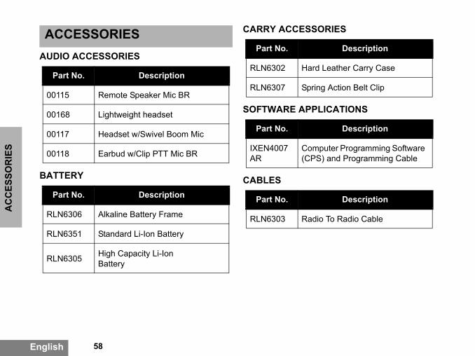
ACCESSORIESAUDIO ACCESSORIES
BATTERY
CARRY ACCESSORIE
SOFTWARE APPLICA
CABLES
Part No. Description
00115 Remote Speaker Mic BR
00168 Lightweight headset
00117 Headset w/Swivel Boom Mic
00118 Earbud w/Clip PTT Mic BR
Part No. Description
RLN6306 Alkaline Battery Frame
RLN6351 Standard Li-Ion Battery
RLN6305 High Capacity Li-Ion Battery
Part No.
RLN6302 Hard Leat
RLN6307 Spring Act
Part No.
IXEN4007AR
Computer(CPS) and
Part No.
RLN6303 Radio To R

59 English
AC
CESSO
RIES
ssories may be or may e of purchase. Please t of purchase or visit r www.motorola.com/ nformation on
ging Kit includes Power ger, and AC Pin adaptors.e or not available at the ontact your Motorola ww.motorola.com/XTNi
ios/business for latest s.
horized dealer for s new models information
CHARGERS Note:(*) Attention: Certain accenot be available at the timcontact your Motorola poinwww.motorola.com/XTNi oradios/business for latest iaccessories.(**) European Rapid CharSupply, Drop-in Tray CharCertain accessories may btime of purchase. Please cPoint of Purchase or visit wor www. motorola.com/radinformation on accessorie
Contact your Motorola autavailability and accessorie
Part No. Description
IXPN4019AR
Rapid Charging Kit - European (**)
IXPN4020AR
Multi-Unit Charger (MUC) Kit - European


her trademarks indicated .S. Pat. & Tm. Off. All
espective owners. © 2007
MOTOROLA, the Stylized M Logo,XTNi Series and all otas such herein are trademarks of Motorola, Inc. ® Reg. Uother product or service names are the property of their rMotorola, Inc. All rights reserved.
Motorola® XTNi Series
*6871663M06*6871663M06-A