moyes delta gliders pty ltd xtralite 137 & 147 owner's manual · pdf filemoyes delta...
TRANSCRIPT

MOYES DELTA GLIDERS PTY LTD
XTRALITE 137 & 147 OWNER'S MANUALCONTENTS Page No.1. Description of Design 12. Specifications 23. Operating Limitations 34. Disclaimer 45. Getting Started-Assembly From 4 m Breakdown 56. Assembly Procedures 67. Pre-Flight Check 128. Derigging the Moyes XTRALITE 149. Flying the Moyes XTRALITE 1710. Tuning Hints 1911. Glider Care 2012. Maintenance Schedule 2213. List of Fasteners and Bolt Tightening Procedure 2414. Checking Stability Systems 2515. HGMA Compliance Verification Specifications 2616. Polar - Xtralite 137 2817 List of Spare Parts 2918. Purchase Record I Maintenance Log 31
DESCRIPTION OF DESIGN The Moyes XTRALITE combines the successful design philosophy of thepopular "XS" and "GTR" series with the technology of the future. TheXTRALITE has been developed to meet the demand for greater performancein combination with lighter bar pressures in both roll and pitch. This hasbeenachieved without sacrificing the traditional Moyes qualities of stability,structural integrity and sleek finish.
The elliptical shape and thinner profile created by the fiberglass tipreduces wing tip vortices whilst the weight saving results in a lower momentofinertia thus reducing roll pressures.
The large mylar reinforced leading edge and closer batten spacing givesthe Moyes XTRALITE a solid, distortion free airfoil while a cunninglyenclosed variable geometry system allows the keel pocketless high-techcomposite sail to produce an amazing lift/drag performance throughout theentire and extensive speed range.
By the combination of stainless steel reflex bridles* and compositealloy/fiberglass battens*, the new Moyes XTRALITE displays excellent pitchstability and dive recovery.
The overall finish and structure of the Moyes XTRALITE is of the usualquality standard.
* Alteration of these devices in any way may reduce the glider's pitchstability or positiveness.
MOYES XTRALITE 137 & 147 SPECIFICATIONSModel / Size XTRALITE 137 XTRALITE 147Area l37sqft 12.Smsq l47sqft 13.7msq
Span 32'3" 9.85 m 33'8" 10.3 mNoseAngle l3Odeg l3Odeg l3Odeg l3OdegAspect Ratio 7.6 7.6 7.7 7.7Glider Weight 68 lb 31 kg 72.5 lb 33 kgPilot Hook-in Weight 130-240 lb 59-110kg 160-250 lb 72-113 kgOptimum (Pilot Only)Weight Range 130-165 lb 60-75kg 155-185 lb 70-85kgPilot Rating Adv Adv Adv AdvPack-up Length 16'2.112" 4940 mm 16'l0.3/4" 5150 rumBreakdownLength 13'6" 4145mm 14r2r1 4320mmShort Breakdown Length 12'3.1/2" 3750 mm 12' 3.1/2" 3750 mm(Unbolt X-bar/L-E Junction) 12'2" 3708 mm 12'2" 3708 mmCofG-FrontofKeel-Powerib 51.3/4" 1315 mm 52.3/4" 1340 mmC of 0-Front of Keel-Mylar 52.1/2" 1333 mm 53.3/8" 1355 mmNumber of Battens - Mainsail 18 18 20 20 -Undersurface 8 8 8 8V.N.E. 53mph 84.8 kph 54 mph 86.4 kphV.A. 46mph 73.6 kph 47mph 75.2 kphTrim Speed 21 mph 33.6 kph 21 mph 33.6 kphStall Speed 16mph 25.6kph 15mph 24kphMaximum Speed 62 mph 99.2 kph 62 mph 99.2 kphBest Glide Speed 26 mph 41.6 kph 26 mph 41.6 kphBest Glide Angle 13.02/1 13.02/I 13.02/I 13.02/IGlide Angle 10/I 35mph 56 kph 35mph 56 kph
Sailcloth Panel A Leading Edge Scrim Panel B Front Mainsail 4oz Dacron Option Mylar Panel C Trailing Edge Powerib Option Mylar Panel D Front Undersurface 4oz Dacron Panel F Back Undersurface 4oz Dacron
OPERATING LIMITATIONS
Your Moyes XTRALITE is a sophisticated, "state of the art" highperformance hang glider and if maintained correctly will give you years ofsafe enjoyable soaring. However, it is important that you display a healthyrespect for all aspects of aviation and that you especially understand theincreased risks of flying in dangerous conditions or in a manner that exceedsthe gliders operating limitations.
Flight operation should be limited to non-aerobatic manoeuvres wherethe pitch angle does not exceed 30 degrees up or down of the horizon, or bankangles exceeding 60 degrees.
The Moyes XTRALITE has been designed for foot launched soaringflight and should not be flown by more than one person at a time, and shouldnot be flown backwards or inverted.
The recommended minimum pilot skill level is Advanced (Hang 4).
The Moyes XTRALITE should not be flown with auxiliary power.
The Moyes XTRALITE should not be flown in excess of the placarded
V.N.E. (maximum speed never to exceed) OR V.A. (maximum roughair manoeuvring speed) XTRALITE 137 XTRALITE 147 V.N.E. 53 mph / 84.8 kph 54mph / 86.4 kph V.A. 46mph/73.6kph 47 mph/ 75.2 kph
The stall speed with maximum pilot weight is

XTRALITE 137 XTRALITE 147 26 mph/ 41.6 kph 29mph/46.4kph
The maximum speed with minimum pilot weight is XTRALITE 137 XTRALITE 147 44mph /70.4 kph 44mph / 70.4 kph
The Moyes XTRALITE will resist spinning and will recover quicklyifcontrol pressures are relaxed. Recovery from a stalled turn can be achievedwithout extreme height loss or without extreme attitude change if the angleofattack is reduced. Recovery from such an incipient spin will be achievedwithinhalf a turn if this procedure is followed.
These standards require ultimate load tests at:I. Maximum lift angle of attack at a speed of 65 mph/l04 kph.2. Negative 30 degrees angle of attack at a speed of 46 mph I 73.6 kph.3. Negative 150 degrees angle of attack at a speed of 32 mph I 5 .2 kph.
34. Pitching moment tests at 20/32,36/57.6 and 53/84.8 mph/kph respectively, (Moyes includes testing to 70 mph/112 kph) to display the gliders inherent positive pitch stability through a broad range of angles of attack.
NOTE: The luff lines on both the Moyes Xtralite 137 & 147 are set tightwith the glider's FULL VG 'ON', we suggest you relax the VG by 18 ' or45 cm when the glider is new . The initial setting of the luff lines iscalculatedusing a glider which has been 'flown in' -
It is recommended that the pilot hold a minimum advanced rating orequivalent, with the following recommended pilot weight range.
XTRALITE 137 XTRALITE 147Pilot Hook-in Weight Range 130-240 1bs/59-110 kgs 160-250 lbs/72-1l3kgsOptimum Pilot Weight Range 130-165 lbs/6O-75 kgs 155-185 lbs/70-85kgs(Without harness)
The Moyes XTRALITE 137 & 147 are capable of flying at speedsgreater than the V.A. (47 mph) (75.2 kph) and V.N.E. (54 mph) (86.4 kph).We recommend you use an accurate airspeed indicator to familiarize yourselfwith control bar positions at these speeds and normal flying speeds.
DISCLAIMER:
The owner and operator must understand that due to the inherent riskinvolved in flying such a unique vehicle, no warranty is made or implied ofany kind against accidents, bodily injury or death. Operations such asaerobatic manoeuvres or erratic pilot technique may ultimately produceequipment failure and are specifically excluded from the warranty.
This glider is not covered by product liability insurance, nor has itbeendesigned, manufactured or tested to any state or federal governmentairworthiness standards or regulations. 4
GETTING STARTED - Assembly from 4 Metre Breakdown If your Moyes XTRALITE was shipped to you in the breakdown form,

you can reassemble your glider to it's full length by following theseprocedures. You will not need any tools. All references to 'top' & 'bottom'and'left' and 'right' are referred to with the glider in flying mode.
1/ Check your packing list.
* Glider * 2 x Backsection leading edges-Right=Green=1 slot Left=Red=2 slots * 2 x Batten Bags - Right=Green - Left=Red * 1 x Speed Bar * 2 x Tip Bags * 3 x Padding Pieces - Kingpost Top, A-Frame Bottom, Keel * 1 x Batten Pattern * I x Snack Pack
2/ Expose the leading edge/cross bar junction through the tip inspection port. Remove the bubble wrap and tape from the leading edge/cross bar junction and the end of the middle sleeve.
3/ Insert the fight hand back section of leading edge. The right hand back section is indicated by a green spot and 1 slot in the black eccentric ring. Ensure that the black eccentric ring is pushed all the way into themiddle sleeve so that the black eccentric ring is not exposed at all. Ensure that the black eccentric ring is located so that the thinner wallof the ring is on the bottom.
4/ Secure the back section by attaching to the tip webbing using the clevis pin and ring supplied. Ensure the tip webbing is not twisted, and is on the bottom of theleading edge, making sure to locate the aluminium fibreglass tip mount tube.
5/ Repeat numbers 2/ - 4/to install the left hand back section of leading edge. The left hand back section of leading edge is identified by a red spot and 2 slots in the black eccentric ring.
5

ASSEMBLY PROCEDURES1/ Place the glider on the ground, zipper up. Open the bag, undo ties,remove padding and battens and assemble control frame.Check that no wires are twisted around the control frame. Fig. 1
Check that assembly bolt has actually passed through the basebar andaluminium knuckle and is held with castle nut and safety pin. Fig. 2

2/ Roll the glider over so that it is standing on the control frame
Special care should be taken, to assure that the control bar top does notdamagethe leading edges, when turning the glider over and laying flat on theground.
Check that the control frame is central and that the wires are not kinked ortwisted, especially the bottom side wire and tang. Fig. 3

63/ Remove glider bag and any remaining ties and padding. Carefullyspread each wing making sure that you do not raise them above the keel andthat bridles or rigging are not snagged around keel or kingpost.
4/ Raise the kingpost and attach rear wire and reflex bridles. Fig. 4
Check that bridles are not twisted on themselves and/or other top wires.
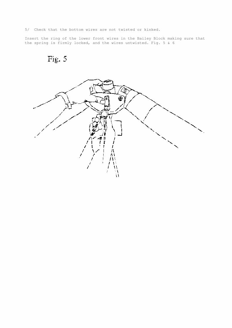
5/ Check that the bottom wires are not twisted or kinked.
Insert the ring of the lower front wires in the Bailey Block making sure thatthe spring is firmly locked, and the wires untwisted. Fig. 5 & 6

76/ Check the battens for symmetry
* Red tipped numbered battens are for the left wing, green for the right andblue the undersurface.* Insert battens from the root out towards the tip, #1 - 6 only. Battens #7 -10are best done after tensioning the cross-bar to avoid catching the ground anddamaging the sail.* Use only gentle pressure when sliding in battens. If resistance isencountered,lift trailing edge and flick it up and down gently in order to billow thesail overthe bar that is stopping the batten. Secure the battens with doubled elasticcords.* Special care should be taken when inserting batten numbers 1-3 so as not todeform their shape. Ensure that the sail is loose enough to allow the battenstoslide in with minimal sail pressure for flat assembly. Fig. 7 & 8


7/ To tension the crossbar pull thecord coming out of the keel aft of thesail until the "U" shackle can be finedover and into the Bailey Block catch onthe keel.Check that the cable and rope are nottwisted and that the spring lock isfirmly locked. Fig. 9
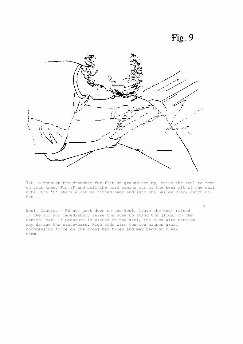
7/F To tension the crossbar for flat on ground set up, raise the keel to reston your knee. Fig.9F and pull the cord coming out of the keel aft of the sailuntil the "U" shackle can be fitted over and into the Bailey Block catch onthe
8keel. Caution - Do not push down on the keel, leave the keel raisedin the air and immediately raise the nose to stand the glider on thecontrol bar. If pressure is placed on the keel, the side wire tensionmay damage the cross-bars. High side wire tension causes greatcompression force on the cross-bar tubes and may bend or breakthem.

8/ Open zipper at sail tip to allow access to inside of sail. Slidefibreglassrod through end of sail and locate in the end of the leading edge. Ensurethatthe fibreglass rod is pushed hard against its stop.Fit plastic cup of the tip lever to the end of the tip rod and tension tip byrotating the flat end of the tip lever inboard, for extra leverage, placeyourthumb through the loop that is attached to the end of the tip lever. Makesurethe tip lever is locked against the tip rod. Close zipper. Fig. 10 & 11


9
9/ Insert tip battens and undersurface battens ensuring that theundersurfacebatten tips rest beneath leading edge. Fig. 12

10/ Insert the nose batten. The batten may need some 'feeding" through thesail by pulling the sail forward to r6move any wrinkles as the batten slidesintoits pocket.
Check that the nose batten sits over the lug on the keel securely. Fig. 13

10Fit tile nose fairing using the velcro to keep a clean trim finish. Fig. 14
11/ Check that the variable geometry cord runs freely into the top of thefaired upright and is held by the cleat on the base bar.
12/ Check that hang loops are secure and attach harness.

11
PRE-FLIGHT CHECK As with most high performance hang gliders, much of the hardware andstructure is well enclosed to give a streamlined finish to the wing. Thismeansthat you must look inside the sail to check many of the important structuralcomponents.
You should develop a consistent routine that incorporates all thenecessary checks. If you are distracted during the routine, you should startagain to ensure nothing has been missed.
1/ As you should have already attached your harness to the glider, checkthat is set up correctly. Ensure that parachute is well maintained and stowedappropriately and the bridle runs cleanly to the carabiner(s) which isattachedvertically to the hang loops. If harness height from basebar needsadjustment, itis best to acquire the correct length loop from your Moyes agent.
2/ Move up hang loops and check they are secure and that no trim changecan occur in flight. Pull down neoprene cover and check kingpost hang loopbolt is tight and safety ring still in place
3/ Open undersurface zip and inspect the cross-bar safety wire and thecompensator cord. Pull V.G. on and off a few times to check that crossbarsare moving freely and V.0. system is operating smoothly and is tied firmly toclip. Inspect interior of each wing, looking at the back side of the leadingedges, the crossbar and the crossbar junctions.
Close undersurface zip.
4/ Check the base of kingpost and apex of control frame ensuring all nutsare secure and thread is showing beyond nut on bolt end.
51 Sight along keel and move to the nose section where all nuts and boltsarechecked. Test nose catch and ensure keel battens are located correctly. Re-attach nose fairing.
6/ Inspect kingpost top, looking for twisted top rigging or snagged reflexbridles. Sight along each leading edge to confirm a similar amount of leadingedge deflexion (curve). Uneven curve will indicate a bent and damaged leadingedge.
7/ Move out along the wing looking and feeling for any damage. Open thezip where the side wires enter the sail and check that both top and bottomwiresare not kinked, twisted or damaged. Check the cross-bar/leading edge junctionbolts and nuts. Close zip on inspection port.
12
8/ Continue out to wing tip and make sure the tip levers are properlyinstalled and that the zipper is closed.
9/ Check all battens as you move along the trailing edge and make sure thatthe reflex bridles are not caught on any batten tips.
10/ At the keel, check the top V.0. rope and the crossbar restraining wire.

Check that top and bottom rear wires are properly secured by the clevis pin,and that the safety ring is installed.
11/ Moving across to the other wing, repeat the process as you work yourway back to the nose of the glider. Carefully check the front bottom wiresandnose catch before inspecting the base of the control bar. Check bottom sidewires for frayed strands between thimble and inner nico, and just outboard ofthe outer nico.
12/ Ensure that the control frame assembly bolt passes through the base barand the comer knuckle.
13/ Check that rigging and nuts and bolts are in good order and that V.0.rope is threaded through the jam cleat and is secure.
14/ Check that crossbar ball is centered in its sockets between crossbarhalves.Close center zipper.
15/ Re-check harness, hang loops and carabiner.
When finally preparing to fly, please do a proper hang check ensuringthat legs are through leg loops, that harness zippers work and that allbucklesor clips etc. are closed and working. Look again at your hang loops andcarabiner(s).
Take your time through these checks, an extra 30 seconds here is wellworth a life time of flying enjoyment.
13
DERIGGING THE XTRALITE Disassembly of the XTRALITE is virtually an exact reversal of the set-up procedure, however a few important points must be remembered to avoidunnecessary damage.
1/ Remove the nose cone, detach the nose catch and remove nose batten,battens #7 - 10, and the outboard undersurface batten. You should neverattempt to remove the battens inboard of #7 without releasing crossbartensionas this will flatten the battens and probably damage the batten pockets inthesail.
2/ De-tension and remove fibreglass tip wands. Fig. 15 Twirl sail tip aroundleading edge and fit tip boots. Fig. 16

3/ De-tension crossbar.4/ Once tension is released the remaining top and bottom battens may beremoved and all battens carefully stowed in the bags provided.
5/ When folding wings, ensure that leading edges and keel remain in thesame plane and that no sail has caught between wing and keel.
146/ Fit rear keel protector sleeve over Bailey Block.
7/ Fold and roll the sail loosely but try to avoid folding the tip in thesameplace each time. Fig. 17

8/ Disconnect bridle lines and lower kingpost, ensure all padding is inplace. Stow bridle lines by hooking to top front wire.
9/ Attach ties loosely around glider, going from wingtip to nose, thentighten the ties, moving from nose to wingtip, adjusting the sail so that theleading edge mylar inserts overlap smoothly with no kinks, as shown. Fig. 18

10/ Put the glider bag over the glider, then lay the glider over on its side.
1511! Disassemble control frame. Fold base tube out and lay the entire controlframe assembly back onto the keel. Open the ties and re-secure them over thecontrol frame, enclosing the frame inside mylar. Fit padding to top andbottomof control frame Tuck wires and bars neatly inside the sail Fig. 19 Pull thekingpost hangloop from between the uprights so as not to jamb the kingposthangloop spreader between the keel and leading edge on the 147 or the uprightand keel on the 137.
12/ Place battens between leading edges with the camber to the tail end, Fig.20 then firm up all ties and smooth out the rolled sail before closing thezip.

16
FLYING THE MOYES XTRALITETake-off
The Moyes XTRALITE has a very slight tail heavy static balance andtherefore is very easy to launch in calm or windy conditions. The nose shouldbe held slightly above horizontal with the wings level. Your run should besmooth acceleration with appropriate pitch control for the situation and onceasafe excess of minimum air speed is acquired a slight easing out of the barwillgive a smooth lift-off. In winds in excess of 10-15 mph (16-24 kph), somewireassistance may be required.
Using the Speed Range
Even at speeds very close to stall, the Moyes XTRALITE retains an
unusual amount of control-ability for a modem high-performance wing. This,when combined with the excellent sink rate gives some distinct advantages inlight lift situations, although you should not fly your glider too slowlywhenscratching near hill. . . . leave a margin for error.The stall characteristics are much the same as for all high performancewings,although the broad "mush" mode achieved by a gradual push out does end witha fairly crisp nose drop or wing drop if on a bank. Remember that suddenentry to a stall with an excessively high nose is one of the most dangerousanduncontrollable manoeuvres possible and can result in a tailslide and apossiblesevere tumble.It is important that you develop skill in choosing the optimum speed to flyforany situation be it turning in lift or maximizing your glide.At the top of the speed range, the glider becomes quite sensitive to eitherpilotinput or turbulence, but will track comfortably if you hold your weightsteady.To slow down from a high speed run, release the pressure on the control barslowly, otherwise the glider will pitch up rapidly and strongly.Sudden pitch input is not desirable in any glider but the quickness ofresponseand energy retention of the Moyes XTRALITE makes it important that yourcontrol is smooth and precise. The glider will reward you with accuracy andimmediate response to your command.
Turning
Although very controllable at low speeds, the Moyes XTRALITE willreturn its most snappy performance at speeds between minimum sink and bestLID. The bank and radius desired will determine both entry speed and weightshift as well as the amount of pitch input required to coordinate themanoeuvre. One of the distinct advantages of the Moyes XTRALITE is its ability tobe t1square" turned, i.e. a constant turn in radius can be kicked through afurther 90 degrees without bank angle increase. This is achieved by acombination of controlled yaw input and a quick push out. It is extremely
17bandy when a thermal core is hard to follow and the normal turn radius wouldtake you into sink Once again be aware of incipient spin developing from toomuch pitch input in this $situation. If the glider does stall in the turn, quickest recovery is achieved byincreasing air speed and rolling in slightly to follow the direction of theturn.
Landing
It is best to approach your landing at just above trim speed with only aslight increase in speed once on final, dropping through the last of the windgradient. This little extra air speed should give you positive control and asteady "bleed-off' until it is time to complete the flare. A good flare isbestachieved by moving the hands up to about shoulder height and pushing out andup as soon as the glider fails to respond to the easing out of the bar during'1bleed-off'. Accurate air speed control and sensitivity are the keys toconsistentgood landings in any glider in any situation.
Variable Geometry
Most modem high performance gliders are built with this system,however its value in '"customizing"" the gliders performance and handlingcombinations to suit your particular requirements is often overlooked. The V~0. should be off for both take-off and landing This mellows thestall and handling characteristics, although in light wind take-offs a littletension may be desirable to firm up the rigging. Maximum straight-line performance is achieved by pulling on the V.0.You can expect roll response to decrease, and the possibility of spin toincrease When thermalling it is best to fly with the V.0. off. To get the most out of your Moyes XTRALITE take some time to feeland think your way through the differences. Allow for the fact that your newwing feels and flies differently and will require some adaptation oftechnique ifyou are to utilize fully the potential of the Moyes XTRALITE.
18
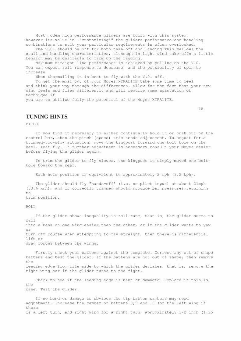
TUNING HINTSPITCH
If you find it necessary to either continually hold in or push out on thecontrol bar, then the pitch (speed) trim needs adjustment. To adjust for atrimmed-too-slow situation, move the kingpost forward one bolt bole on thekeel. Test fly. If further adjustment is necessary consult your Moyes dealerbefore flying the glider again.
To trim the glider to fly slower, the kingpost is simply moved one bolt-bole toward the rear.
Each hole position is equivalent to approximately 2 mph (3.2 kph).
The glider should fly "hands-off' (i.e. no pilot input) at about 21mph(33.6 kph), and if correctly trimmed should produce bar pressures returningtotrim position.
ROLL
If the glider shows inequality in roll rate, that is, the glider seems tofallinto a bank on one wing easier than the other, or if the glider wants to yaworturn off course when attempting to fly straight, then there is differentiallift ordrag forces between the wings.
Firstly check your battens against the template. Correct any out of shapebattens and test the glider. If the battens are not out of shape, then removetheleading edge from tile side to which the glider deviates, that is, remove theright wing bar if the glider turns to the fight.
Check to see if the leading edge is bent or damaged. Replace if this isthecase. Test the glider.
If no bend or damage is obvious the tip batten cambers may needadjustment. Increase the camber of battens 8,9 and 10 (of the left wing ifthereis a left turn, and right wing for a right turn) approximately 1/2 inch (1.25

cm), as shown in the drawing.
A lessening of the camber on the other wing in the same fashion can be triedifthis has not solved the problem.
19
GLIDER CARE Your Moyes XTRALITE will require very little in the way ofmaintenance if you take a little extra time and care with your day to daytreatment and use
Storage
• Keep the glider in its bag in a cool dry place. Store the glider off thefloor or ground and free from contact with oils, solvents or acidicsubstances.Always dry the glider completely before storing. If this is not possible,ensurethat the glider bag is off or open and that the sail is loose enough for airtocirculate. Dry completely as soon as possible.
Sail Care
It is important to keep the sail clean and free from salt if you fly nearthecoast. Regular rinsing with fresh water will achieve this but for thoroughwashing a mild detergent may be used provided it is completely rinsed off thesail. For more serious stains consult your local sail-maker or Moyes dealer. For small tears apply sail repair tape to prevent fraying. Unless thetearis at a stress point or along the trailing edge it will not tend to run orexpand. Sun and exposure to the elements will deteriorate the sail more rapidlythan hours of flying. It is important to carry the glider in its bag on wellpadded roof bars with at least three points of support.If you take just a little extra care when packing up and transporting theglider,it will maintain its condition and performance for many more enjoyable hours.
Battens
Never force the battens into their pockets. Insert them gently to avoiddamage to the sail and wear to the batten ends. Sand in the sail or on thebattens will cause abrasion in the pockets . . batten pocket repairs arecostly. Always pack the highly cambered battens (nose to #5) into the batten bag

as a unit, never one at a time. This will avoid flattening the camber. Storethetwo bags of battens securely between the leading edges with the camber to thevery end so that the tie downs for transport do not pull across the camber. If reshaping is required, take care to avoid over working the tube asthiswill soften the alloy causing the battens to lose shape more easily in thefuture. Never insert or extract battens with the cross-bar tension on . . . tipbattens and undersurface battens excepted. Note: The Moyes XTRALITE has an extremely steep profile for battensnumbered 1 ,2,and 3 and extra special care is recommended, that is, do notremove battens while there is tension on the sail.
20Wires and Attachments
At the first sign of frays or kinks the wire should be replaced.Stainlesssteel cable work-hardens from bending, especially where it enters or exits anico sleeve. The shrink tube covering the nico sleeve should be peeled backperiodically to inspect the cable. Constant exposure and set-up on rough androcky ground and salty sand and sea air will shorten the riggings life. Wiresare not expensive and are simple to replace, they also bold your glidertogether.
Tubing and Bars
Once again contact or immersion in salt air or water is a major concernand will require removal of end caps and a thorough flushing and drying.Corrosion and electrolysis set in amazingly quickly and will dramaticallyreduce the strength and life of the parts involved. Follow the maintenanceschedule conscientiously. Examine the bars for dents, bends, wear spots andcorrosion every pre-flight check. If any damage is noticed, replace the bar,butalso determine how that damage was caused and take steps to avoid repeatdamage occurring.
Hardware and Bolts
The bolts can be bent in a crash or hard landing . . . these should bereplaced. All bolts should show exposed thread above the locknuts.The fibreglass tip can be broken if you slip or stall onto the wing tipduringlanding . . . check and replace if delamination of the fibreglass is evident.
21
Maintenance ScheduleEvery 10 hours
Check all battens against airfoil template.
Every 50 Hours (or six monthly)
1. Inspect the sail. Check tile stress areas and apply sail repair tapewherenecessary. Special attention should be directed to the wire slots, kingpostsopening and reflex bridle attachments tabs.2. Inspect all batten elastics and tip cords.3. Inspect all cross-bar wires, fittings and hardware.4. Check all bars/tubing for damage or possible wear caused by set-up,

fold-upor transportation.5. Inspect all rigging for frays and other signs of damage or deteriorationsuch as rust.6. Lower side wires must be replaced every 50 hours.
Annual Inspection
1. Every 100 hours air time (or every 12 months) the glider should becompletely stripped down for a thorough inspection.2. All rigging must be replaced every 100 hours or at first sign of wear.This can be done by yourself or preferably by your Moyes dealer or agent.
Sail Removal
1. Remove sail attachment screws from nose and rear of keel.
2. Remove top side wires from L.E./crossbar junction (5/1611 bolt) andbottomside wires from crossbar plate (1/411 bolt).
3. Remove top front cable from nose plate.
4. Fold kingpost back toward rear of keel.
5. Remove sail attachments clevis pins from leading edge tips.
6. Undo central zipper entirely and remove plastic cable tie at nose ofsail.
7. Slide frame forward and out of sail.
22General Inspection
* Check the sail for abrasion and tears. Check all stitching and have anyrepairs done by a professional sail maker.
* Replace batten elastics and tip cords.
* Closely inspect all other glider components and replace any part that isdamaged or worn. Pay special attention to reflex bridles, hang loops andrigging. Replace these even if they show only minor wear (Some pilotsreplace bottom rigging every year (75-100 hours) regardless of wear. Coastalflyers should consider this due to increased contact with salt and corrosiveagents.)
23
CHECKING STABILITY SYSTEMSMeasurement Procedure With the glider fully assembled, sitting on the A-Frame, and resting onthe keel tube, run a string taughtly from the end of the batten tip (seediagram)across the top of the keel tube to the corresponding batten on the other side Measure the distance between the string and the top of the keel tube (seediagram). Verify that the distance is within +1-318" of those shown in thechartbelow. Move the string to inspect each luff line, checking both loose and tightsettings. Adjust the luff line height compensator as necessary to get the most

accurate distribution of heights as indicated by the chart.
MODEL-SIZE-SAIL SETTING BATTEN NUMBERS 4 5 6 7XTRALITE 137 POWERIB LOOSE 3.3/8" 4.5/16" 4.1/8" 2.7/8" TIGHT 1.15/16" 2.5/16" 1.3/4" 7/16"XTRALITE 137 MYLAR LOOSE 3.15/16" 4.3/4" 4.1/2" 3.3/4" TIGHT 1.1/2" 1.3/4" .7/8" 0XTRALITE 147 POWERIB LOOSE 3.1/8" 2.5/8" 2.7/16" 1/1/4" TIGHT 1.5/8" 1.3/4" 1.1/8" 0XTRALITE 147 MYLAR LOOSE 2.1/2" 2.5/8" 2.1/8" 1/4" TIGHT 3/4" 5/8" 0 -1.3/4"