mpc 75 feasibility study - summary report · this report summarizes the study results jointly...
TRANSCRIPT

Feasibility Study - Summary Report
MBBAssociation
- Project Definition

Diese P r o j e k t - D e f i n i t i o n
ist ein Auszug aus dem Summary Report (Kapitel B1) »dokumentiert den
Projektstand zum Ende der Feasibility Study und gilt als:
MPC 75 Project Information
Issue 2 (07/87)
Ref.: TE15 - 114/87
MBBAssociatlon
LIST OF CONTENTS
1.
2.
3.
4.
5.
6.
7.
8.
9.
10.
INTRODÜCTION
REVIEW OF ACTIVITIES
DESIGN REQUIREMENTS
BASELINE AIRCRAFT
ALTERNATIVE CONFIGURATION WITH PW-ALLISON 5O1-M80E
ADVANCED TECHNOLOGIES
ENGINE CHOICE
COMPETITION
ECONOMICS
CONCLUSIONS
LIST OF APPENDICES
MBBAssoclation
INTRODUCTION
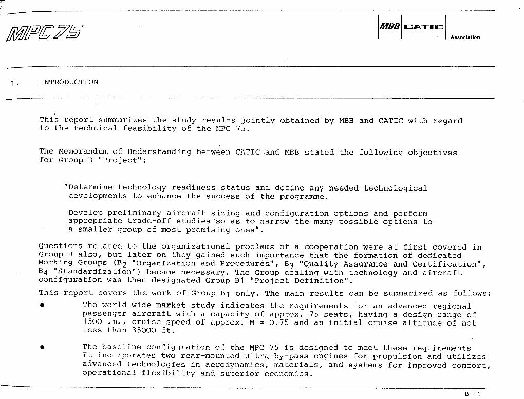
This report summarizes the study results jointly obtained by MBB and CATIC with regardto the technical feasibility of the MPC 75.
The Memorandum of Understanding between CATIC and MBB stated the following objectivesfor Group B "Project":
"Determine technology readiness Status and define any needed technologicaldevelopments to enhance the success of the programme.
Develop preliminary aircraft sizing and configuration options and performappropriate trade-off studies so äs to narrow the many possible options toa sinailer group of most promislng ones".
Questions related to the organizational problems of a cooperation were at first covered inGroup B also, but later on they gained such importance that the formation of dedicatedWorking Groups (B2 "Organization and Procedures", B3 "Quality Assurance and Certification",64 "Standardization") became necessary. The Group dealing with technology and aircraftconfiguration was then designated Group B1 "Project Definition".
This report covers the work of Group B-\. The main results can be summarized äs follows:
• The world-wide market study indicates the requirements for an advanced regionalpassenger aircraft with a capacity of approx. 75 seats, having a design ränge of1500 .m., cruise speed of approx. M = 0.75 and an initial cruise altitude of notless than 35000 ft.
« The baseline configuration of the MPC 75 is designed to meet these requirementsIt incorporates two rear-mounted ultra by-pass engines for propulsion and utilizesadvanced technologies in aerodynamics, materials, and Systems for improved comfort,operational flexibility and superior economics.
Bl-l

MBBAasociatlon
INTRODUCTION
The MPC 75 baseline configuration has a four abreast cabin cross section. With32 inches seat pitch, the capacity of a single class layout is 76 seats- With 30inch seat pitch in a high density layout, the seating capacity is increased upto 84 seats.
The performance analysis ahows that the baseline configuration meets all techni-cal and market requirements, including the ciritical mission of Kunming-Chengdu.
The MPC 75 is very competitive in terms of block fuel and direct operating costcompared with the existing aircraft of the same class.
The engine availability study shows tha.t only the QE38 UDF is a suitable candidatepowerplant so far, but the PW-Allison 5Q1-M80E engine and other alternatives arestill under consideration.
The results of the feasibiüty study demonstrate that the MPC 75 aircraft is tech-nica.lly feasible, but further refinement of the baseline configuration is stillnecessary. Especially the requirements of potential customers must become betterknown, and must be reflected in the final configuration.
R1 -

MBBAsaoclatlon
2. REVIEW OF ACTIVITIES
2.1 Way of working
MBB and CATIC discussed and agreed the overall work plan, and performed the study in closecooperation.
Typically, detail work was done independently in the parent companies; results were ex-changed in the context of a General Meeting; conclusions were then drawn and detail workplans were established covering the period up to the next meeting. However, on twooccasions, CATIC engineers stayed at MBB in Hamburg for an extended working period äs theStatus of work required so.
2.2 Main lines of action
Initially, three actions were carried out in parallel: assessment of technical requirements(derived from market needs), assessment of Status of technology, and comparison of methodo-logy (using an example aircraft). A Baseline Aircraft was then defined, and was optimizedand refined by means of parametric variations, trade-offs, and some analysis of criticalcomponents and Systems. This Baseline Aircraft was used in presentations to selected air-lines (CAAC, LH), thus stimulating a first market reaction to MPC 75.
The question of propulsion/engine availability was dealt with äs a priority item, and regu-lär contacts with engine manufacturers were maintained.
2.3 Major Events
26.1.86 to 6.2.86
Hamburg
Time schedule and work procedure of Group B agreed.
Example aircraft selected to check consistency of engineeringmethods of MBB and CATIC.
MBBAssoclatlon
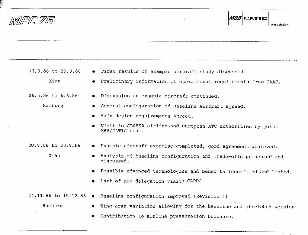
13.3.86 to 25.3.86
Xian
26.5.86 to 6.6,86
Hamburg
• First results of example aircraft study discussed.
• Preliminary Information of operational requirements from CAAC.
• Discussion on example aircraft continued.
• General configuration of Baseline Aircraft agreed.
• Main design requirements agreed.
• Visit to CIMBER airline .and European ATC authorities by jointMBB/CATIC team.
• Example aircraft exercise completed, good agreement achieved.
• Analysis of baseline configuration and trade-offs presented anddiscussed.
• Possible advanced technologies and benefits identified and listed
• Part of MBB delegation visits CARDC.
24.11.86 to 19.12.86 • Baseline configuration improved (Revision 1)
Hamburg • Wing area Variation allowing for the baseline and stretched Version
• Contribution to airline presentation brochure.
20.9.86 to 28.9.86
Xian
n i

MBBAssoclatlon
23,2.87 to 13.3.87 • Baseline configuration finished for feasibility study.
Hamburg
22.4.87 to 30.4.87
Hamburg
• Results of alternative configuration with. PW-Allison enginereviewed.
• Feasibility of advanced structure (CFRP wing box) and advancedaerodynamics (NLF) discussed, conclusion positive.
• Major Systems discussed, suitable Solutions identified.
• First contact with 13 European airlines established to improveinformation on design requirements.
« First draft of Technical Description available.
13.5.87 to 20.5.87
Guilin
Summary Report drafted and agreed.
2.4 General Results
The work carried out in 1986/87 has demonstrated that engineers from CATIC and MBB areable to cooperate succesfully in defining an aircraft, despite still existing problemscaused by the large distance and part-lally insufficient communication lines. A very highdegree of agreement was achieved in all technical matters covered. Discussions and workingsessions took place in 'a professional, matter-of-fact, but open and friendly atmosphere.

MBBAseoclatlon
3. DESIGN REQUIREMENTS
Baalc market requtrements obtained frorn the Market Group were translated into a set ofDesign Requirements, see Fig. 3.1. In general, performance requirements stated are similarto the level of contemporary regional airliners.
The nature of this inforroation is still very preliminary and limited. More substantiationis highly deairable in order to establish a better yardstick against which the aircraft canbe compared.
The only specific roission requirement so far was that indicated by CAAC: A flight fromKunming to Chengdu, involving high, elevation, high temperature airfield performance, seeFig. 3.2.
In order to improve the Situation on the requirements side, some additional information wascollected froro a limited number of European airlines, on the basis of initial, generalcontacts. These contacts are not fully representative; in addition, uncertainties exist onthe operator's side because the effect of the anticipated liberalizatiön and the changingenvironment in Europ'e is not yet fully assessable.
Neyertheless, from this information and the latest inputs received from local administra-tions of CAAC, the following preliminary conclusions may be drawn:
There is some confirmation of the Basic Project Requirements, but on the other handthere appears to be a trend towards a requirement for increased passenger capacity,more cabin comfort, and less ränge.

MBBAssociallon
Fig. 3.1: SUMMARY OF DESIGN REQUIREMENTS
Capacity Start with 75 seats, 32" pitch single class. Stretch potential to 10Oseats, 32" pitch single class. (Later indication: There is the possi-bility that the above single class recommendation could change tobusiness/economy mixed class with the same number of seats).
Range 150O nm with füll passenger load, but without cargo; provisions forfuture increase.
Cruise speed About M = 0.75
One engine in-operative ceiling 16000 ft, ISA -f 10 C
Take-off fieldPerformance
6000 ft SL, -f ISA + 18 C, MTOW
5200 ft SL, ISA, MTOW
6900 ft, 650O ft elevation, ISA, MTOW
FAR landing fieldlength 430O ft SL, wet runway, Typ. miss. L.W.
Noise FAR part 36 stage III or better
Comfort Similar to F28, (Later recommendation: Perceptive äs well äs physicalStandard comfort level not worse than the 1990's 100-t-seater single-aisle air-
craft; aisle width should consider unobstructed passenger movementswithin the cabin during galley service; airline inputs needed.)
Economics DOC Target: SMC better than current aircraft of the same category;SMC at least equal to F100 with 100 passengers.
Bl-7

MBBAasoclatlon
BASELINE AIRCRAFT
4.1 General
A Basellne Aircraft configuration was defined, fulfilling the initial design requirements.
It must be understood that the Baseline Aircraft is by no means the final solution. It israther a preliminary solution which fits the market needs and is well enough engineered tomatch technical needs äs well.
Hence, the Baseline Aircraft can be reasonably used for checks against requirements orcorapetition aircraft and to indicate the attainable level of payload flexibility, comfort,performance, and economics.
Also/ it serves äs a starting point of optimization and refinement, and it helps to stimu-late reactions from potential customers.
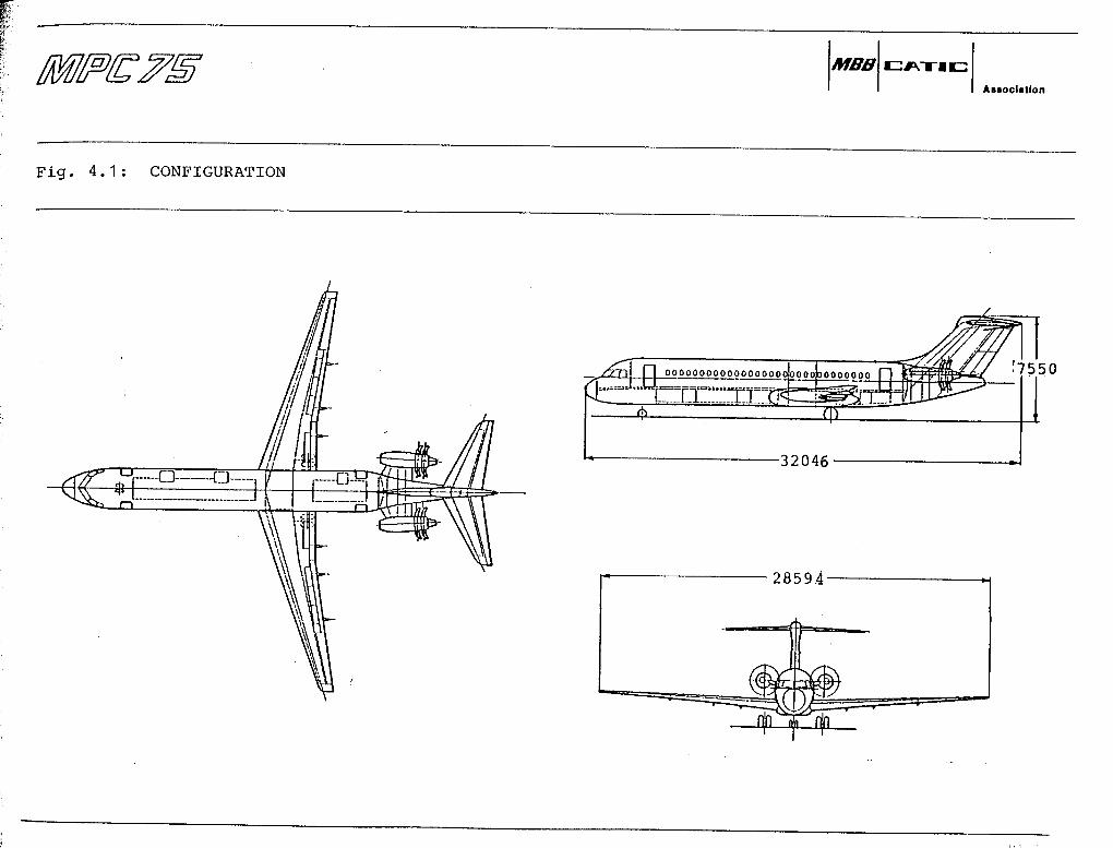
4.2 Configuration'
General
The Baseline Aircraft configuration, äs far äs possifale, reflects the market needs andtechnical possibilities äs seen today. The configuration has been optimized for the basiccapacity of approx. 75 seats. However, there is an inherent capability for future growthto increased capacity and extended ränge.
The Baseline Aircraft reflects the Standards typical of main line operators. New techno-logies have been incorporated where they are expected to be cost effective (see chapt. 5),
MBBAssoclatlon
BASELINE AIRCRAFT
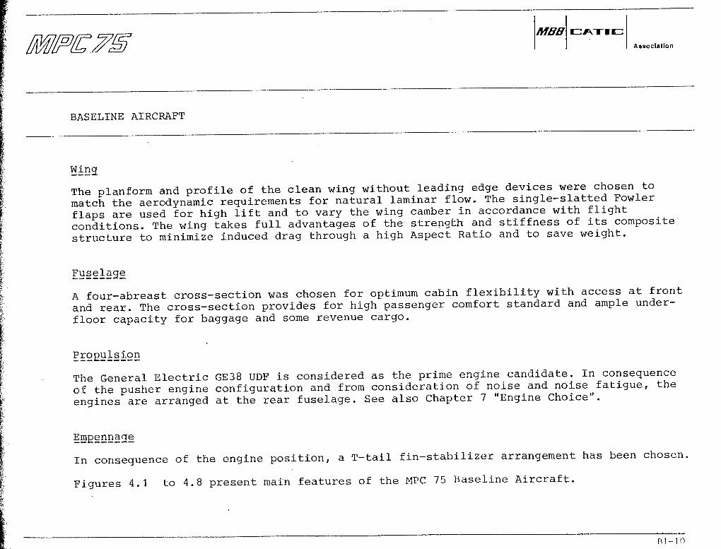
WjLng
The planform and profile of the clean wing without leading edge devices were chosen tomatch the aerodynamic requirements for natural laminar flow. The single-slatted Fowlerflaps are used for high lift and to vary the wing camber in accordance with flightconditions. The wing takes füll advantages of the strengfch and stiffness of its compositestructure to minimize induced drag through a high Aspect Ratio and to save weight.
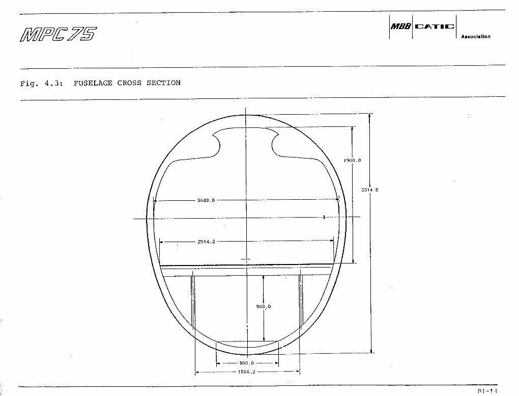
Fuselage
A four-abreast cross-section was chosen for Optimum cabin flexibility with access at frontand rear. The cross-section provides for high passenger comfort Standard and ample under-floor capacity for baggage and some revenue cargo.
Propulsion
The General Electric GE38 UDF is considered äs the prime engine candidate. In consequenceof the pusher engine configuration and from consideration of noise and noise fatigue, theengines are arranged at the rear fuselage. See also Chapter 7 "Engine Choice".
Empennage
In consequence of the engine position, a T-tail fin-stabilizer arrangement has been chosen.
Figures 4.1 to 4.8 present main features of the MPC 75 Baseline Aircraft.
R1-10

MBBAssoclatlon
BASELINE AIRCRAFT
4. 3 Weights
The weights refleqt the latest Status of the Baseline Aircraft definition and include theeffects of using advanced materials and manufacturing techniques. There is confidence thatthe level of weights is realistic äs they are justifiable against existing aircraft of thesame class. Some weight reduction appears possible äs the aircraft definition becomes morespecific. See Weight Summary, Fig. 4.9.
4.4 Performance
The Baseline Aircraft performance reflects the best aerodynamic qualities - including natu-ral laminar flow - that can realistically be assumed at the present state of technology andaircraft definition. Engine data have been used äs furnished by the manufacturer. See Fig.4.10 for the Performance Summary and Fig. 4.11 for Payload-Range.
All performance requirements are met or even bettered. Only the "high altitude T.O. case"(690O ft field length at MTOW, 650Q ft elevation) is not met: this T.O. field can only beachieved at a reduced T.O. weight giving a ränge with 76 passengers of 750 nm. Whether thisis significant, or can be tolerated, can only be clarified through contacts with potentialoperators. It should be noted that the only well defined "hot and high" case is fulfilled:the Kunming-Chengdu mission can be flown even under the most adverse conditions.
4.5 Stretch Potential
A preliminary study has been made on the Stretch potential of the MPC 75. It was found thata stretch of up to approx. 100 seats (äs stipulated by the design requirement) would befeasible. For this Version, MTOW will increase to approx. 34000 kg, and engine thrust mustgrow by some 25 - 30 %. This thrust growth just about appears to be possible for the GE38UDF äs a longer term development. This implies increased engine weight and dimensions. Bothfrom thrust availability and from airframe structural reasons, stretched versions must beconsidered äs mid-to-longterm developments.
ni-11
ossz.
NOIiVHflDIvEtNOD U " f r
UO||B|3O»y
BfETIAI
MBBAssociatlon
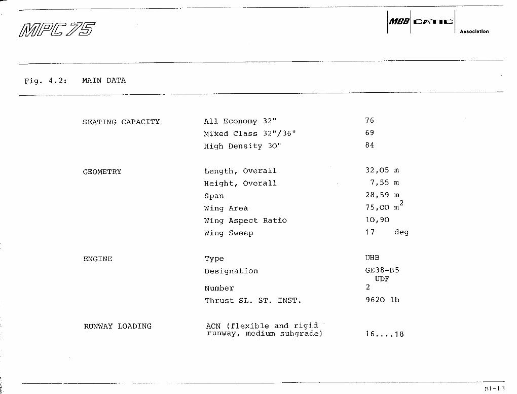
Fig. 4.2: MAIN DATA
SEATING CAPACITY All Economy 32"
Mixed Class 32"/36"
High Density 30"
76
69
84
GEOMETRY Length, Overall
Height, Overall
Span
Wing Area
Wing Aspect Ratio
Wing Sweep
32,05 m
7,55 m
28,59 m
75,00 m2
10,90
17 deg
ENGINE Type
Designation
Number
Thrust SL. ST. INST.
UHB
GE38-B5UDF
2
9620 Ib
RUNWAY LOADING ACN (flexible and rigidrunway, medium subgrade) 16 18
nl-1 3
MBBAssoclatlon
Fig. 4.3: FUSELAGE CROSS SECTION
33U.5
B1-M
MBBAsaoclation
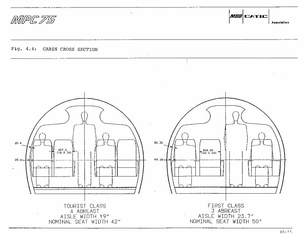
Fig. 4.4: CABIN CROSS SECTION
25.4
25.4
TOURIST CLASS4 ABREAST
AISLE WIDTH 19"NOMINAL SEAT WIDTH 42"
59.30
59.30.-.
\
L508.00
(20.0 IN) ^
1111
1
1
. n ;
_ _
\ /
FIRST CLASS3 ABREAST
AISLE WIDTH 23.7"NOMINAL SEAT WIDTH 50"
Bl-15
MBBAaaoclatlon
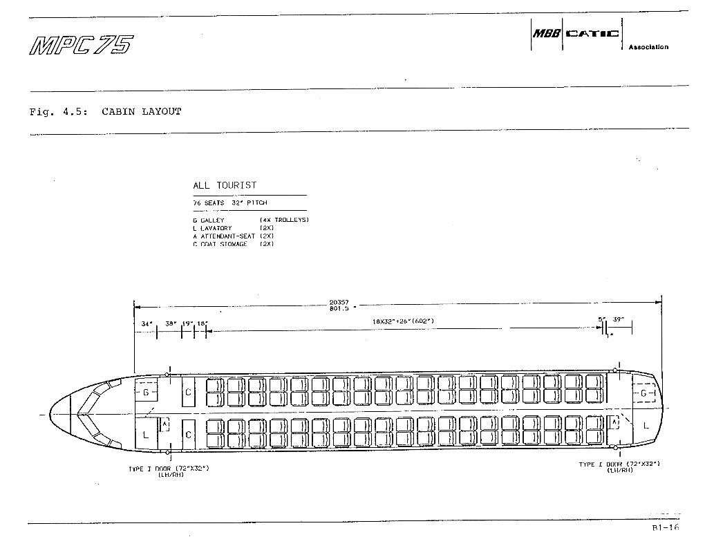
Fig. 4 .5: CABIN LAYOUT
ALL TOURIST
76 SEATS 32' PITCH
G GALLEY (4X TROLLEYS)L LAVATORY (2X)A ATTENDANT-SEAT (2X)C PDA T STOWAGE (2X)
34" , 38" ,19". 18!-
h h
--G-
AI
20357801 .5
18X32"+26-(602") 5" 39"
TYPE I DODR (72"X32")ILH/RH)
TYPE I QDOR (72-X32")(LH/RH)

MIXED CLASS
9 SEATS 36" PITCH60 SEATS 32" PITCH
69 SEATS TOTAL
G GALLEY (5X TROLLEYS)L LAVATORY (2X)A ATTENDANT-SEAT (3X1C COAT STOWAGE <2X)
MBBAssociation
Fig. 4 . 6 : rabin Layout
RH34" . 38" . .20
i-F9.s1
2X36"+27.5"(99.5") 7" 18."
20357801 .5
--G--
A I.j
14X32"+26"(474")
AI
TYPE I DOOR (72-X32')(LH/RH)
TYPE I DOOR |72"X32")(LH/RH)
A 01.027.03 87 R1-17

MBBAssociatlon
Fig. 4 . 7 : Cabin Layout
HIGH DENSITY
84 SEATS 30 PITCH
G GALLEY (4X TRDLLEYS]L LAVATORY (2X)A ATTENOANT-SEAT (2X)S STOWAGE (2X)
0
34' . 38"
--G-
L
20357801 .5
20X30' 3',J' 37'
-H
T
-•GHi
TYPE I DOOR (72"X32")(LH/RH)
TYPE I DOOR (72'X32"1(LH/RH)
A01.0?8.0387 Bl-18

MBBAssoclatlon
Fig. 4.8: CARGO COMPARTMENTS
0000000000000000000000000000000
1 1 11 11 1
L L _)
DOOR NO. t950x900
§$§|§|
DOOR NO. 2950x900
"/ __2S< ~ J3 §
—er!
5.6 CU.MREVENUECARGO
5.0 CU.MBAGS
A.6 CU.MBAGS
'
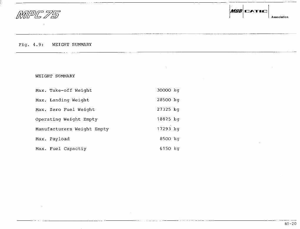
WEICHT SUMMARY
Max. Take-off Weight
Max. Landing Weight
Max. Zero Fuel Weight
Operating Weight Empty
Manufacturers Weight Empty
Max. Payload
Max. Fuel Capactiy
30000 kg
28500 kg
27325 kg
18825 kg
17293 kg
8500 kg
6150 kg
MBBAssoclalion
Fig. 4 . 9 : WEICHT SUMMARY
Bl-20

MBBAssociation
Fig. 4.10: PERFORMANCE SUMMARY
RANGE WITH FÜLL PASSENGER LRC (nm)
RANGE WITH MAX FUEL LRC (nm)
FAR T.O. FIELD LENGTH SL, ISA, MTOW (ft)
SL, ISA+18, MTOW (ft)
65OO ft, ISA, MTOW (ft)
FAR LAND. FIELD LENGTH SL, WET RUNWAY (ft)AT TYP. MISS. LW
ASSOCIATED APPROACH SPEED (kts)
INITIAL CRUISE ALTITUDE 500 ft/MIN, M=0.7 (ft)
1-ENGINE-INOP CEILING ISA+1O°C (ft)
MAX. CRUISE MACH NUMBER (35000 ft)
MISSION KUNMING - CHENGDU
REQUIRED
1500
52OO
6000
6900
4300
-
-
16000
0.75
ACHIEVED
1500
2500
5100
5700
97OO
4200
115
36000
16500
0.76
see Fig.3.2
REMARKS
MET
MET
METRequirement met only atTOW for 750 nm Range
MET
-
-
MET
MET
MET
Bl-21

MBBAaaoclatlon
Fig. 4.11: PAYLOAD-RANGE
PAYLOAD [kg]12000
0000
8000
6000
4000
2000
200nm ALTERNATE30 MIN HOLD5% BLOCK FUEL
000 1500 2000 3000 4000 5000RANGE [nm]
Bl-22
MBBAssociation
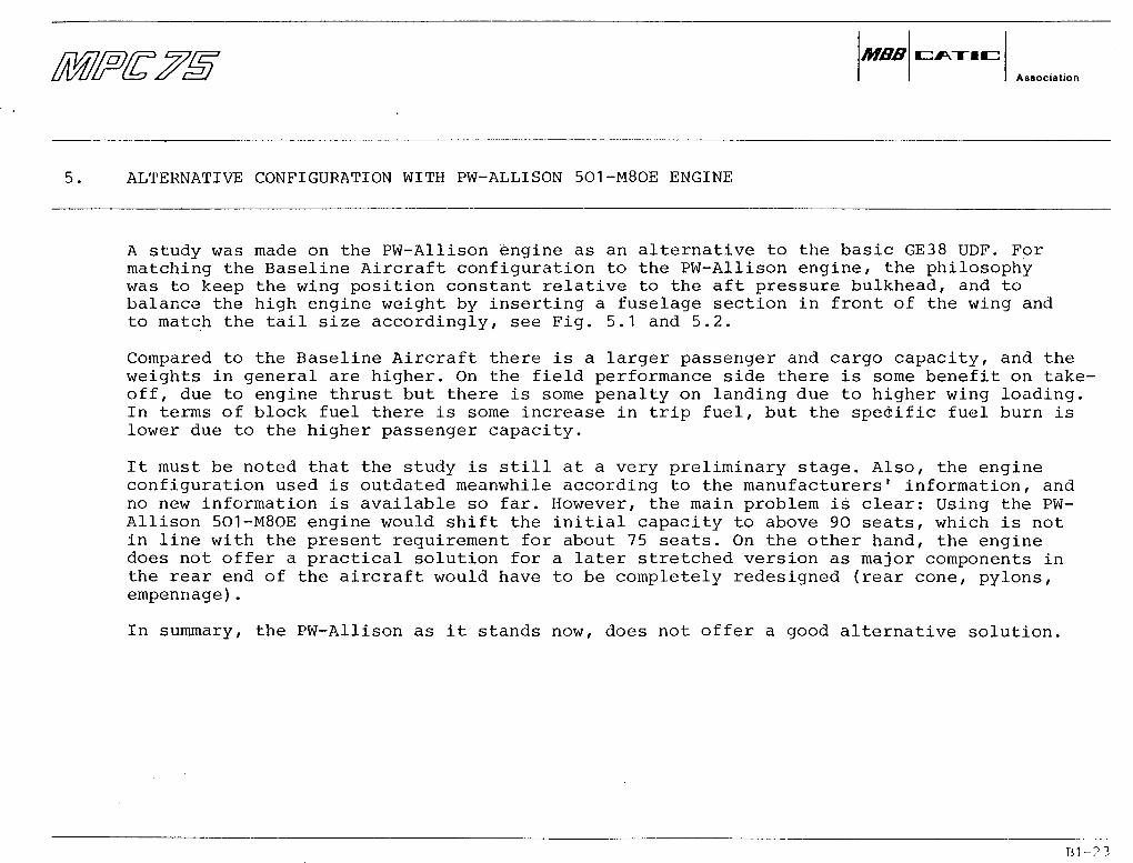
5. ALTERNATIVE CONFIGURATION WITH PW-ALLISON 501-M80E ENGINE
A study was made on the PW-Allison engine äs an alternative to the basic GE38 UDF. Formatching the Baseline Aircraft configuration to the PW-Allison engine, the philosophywas to keep the wing position constant relative to the aft pressure bulkhead, and tobalance the high engine weight by inserting a fuselage section in front of the wing andto match the tail size accordingly, see Fig. 5.1 and 5.2.
Compared to the Baseline Aircraft there is a larger passenger and cargo capacity, and theweights in general are higher. On the field performance side there is some benefit on take-off, due to engine thrust but there is some penalty on landing due to higher wing loading.In terms of block fuel there is some increase in trip fuel, but the specific fuel burn islower due to the higher passenger capacity.
It must be noted that the study is still at a very preliminary stage. Also, the engineconfiguration used is outdated meanwhile according to the manufacturers' Information, andno new Information is available so far. However, the main problem is clear: Using the PW-Allison 5O1-M80E engine would shift the initial capacity to above 9O seats, which is notin line with the present requirement for about 75 seats. On the other hand, the enginedoes not offer a practical solution for a later stretched version äs major components inthe rear end of the aircraft would have to be completely redesigned (rear cone, pylons,empennage).
In summary, the PW-Allison äs it Stands now, does not offer a good alternative solution.

MBBAisoclallon
Fig. 5.1: ALTERNATIVE CONFIGURATION
yp |~| ooooooooooooooooooo ooooo ojo oo ojo oooooooyp |~| ooo„i— LL-i" .......
35811
28594
7885
Bl-24
MBB cz:*vrrii=:Assoclatlon
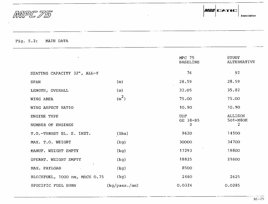
Fig. 5.2: MAIN DATA
SEATING CAP ACITY 32", ALL-Y
SPAN
LENGTH, OVERALL
WING AREA
WING ASPECT RATIO
ENGINE TYPE
NUMBER OF ENGINES
T.O.-THRUST SL. S. INST.
MAX. T. O. WEICHT
MANUF. WEICHT EMPTY
OPERAT. WEICHT EMPTY'l
MAX. PAYLOAD
BLOCKFUEL, 1000 nm, MACH 0.75
SPECIFIC FUEL BURN
MPC 75 STUDYBASELINE ALTERNATIVE
76 92
(m) 28.59 28.59
(m) 32.05 35.82
(m2) 75.00 75.00
10.90 10.90
UDF ALLISONGE 38-B5 501-M80E
2 2
(Ibs) 9620 14500
(kg) 30000 34700
(kg) 17293 19800
(kg) 18825 21600
(kg) 8500
(kg) 2460 2625
(kg/pass./nm) 0.0324 0.0285
Bl-25

MBBAssociation
6. ADVANCED TECHNOLOGIES
6.1 General
During the first part of the feasibility study phase a number of over 5O technology itemshave been considered äs possible candidates for MPC 75. These technologies have beendiscussed with respect to:
• Status of Research and Development worki
• Benefits and Penalties
• Configuration impact
For a number of technologies there were two or more alternative Solutions.
The next step was the preliminary selection of feasible technologies or Optimum technologyalternatives for the Baseline Aircraft.
The technology items finally selected must meet a number of criteria. To mention only themost important ones, they must
• comply with airworthiness requirements
• be economically feasible
• meet the airline's requirements
• be ready according to MPC 75 programme planning
• meet the challenge of competition aircraft
Bl-26

MBBAsaoclatlon
ADVANCED TECHNOLOGIES
'?i
To show the economic feasibility of technologies, detailed trade-off studies based onsuitable data input must be performed. These trade-off studies are under way and firstresults will be available in the second half of 1987. But these optimization procedureswill go on during the pre-development phase up to the GO AHEAD in 1990.
Up to now a presentation of the MPC 75 has been made to only a very limited number of air-lines. From these meetings no requirements were made known which would help in the selec-tion of technologies. Only one general statement is known from the market group: "MPC 75is an airplane for main line operators", i.e. for airlines which are qualified to operateand maintain aircraft of advanced technical Status.
Most technologies are already available or under development at MBB or CATIC and will beavailable in the time frame of the MPC 75 Programme plan. But for a limited number of tech-nologies already existing technology development programmes must be slightly modified tofit in with the MPC 75 goals and time planning. For some technologies detailed developmentprogrammes must be established and put into Operation by the management.
To meet the challenge of future competition aircraft the MBB/CATIC experts will have tomonitor and evaluate the technological developments of potential competitor aircraft manu-facturers. Th±s may provide further guidance in selecting advanced technologies.
For new technologies, airworthiness criteria often are not known at the beginning, but cer-tification rules will be developed in parallel with and strongly influencing the technicalsolution.
From the above remarks it is evident that the first selection of technologies is based onpreliminary Information only and may have to be changed during the pre-development phase.
Bl-27

MBBAasoclatlon
ADVANCED TECHNOLOGIES
6.2 Airframe Technologies
The technology items preliminary selected for the Baseline Aircraft are:
Advanced Aerodynamics:
• Natural Laminar Flow
• Variable Camber to support NLF
There is mutual agreement between the partner companies that natural laminar flow can beassumed for the Baseline Aircraft äs there is confidence that research programmes underway can be made to meet the MPC 75 needs, particularly äs the MPC 75 design parameters areless demanding.
The surface smoothness requirements associated with natural laminar flow are very high but,again, there is confidence that the targets can be met.
Advanced Structures and Materials:
• Composite Wing Structure
• Composite horizontal and vertical stabilizer
• Aluminium-Lithium fuselage
Indications are that a composite wing is feasible. Material properties are not expected topose any problems. Also, some of the more critical problems like surface quality andlightning protection can be solved äs has been concluded from several design studies andspecific research work.
Bl-28
MBBAssociation
ADVANCED TECHNOLOGIES
With regard to advanced metallic materials, again, it is expected that they will beavailable in time, ready to be used, e.g. on the fuselage.
6.3 Systems
The Systems selected for the Baseline Aircraft include the following features which are notStandard on contemporary regional airliners:
• Environmental Control System: Main engine shaft-driven compressor with vapourcycle packs
• Electric Power System: Using an advanced power distribution management System
• Flight Controls: Fly-by-Wire System with mechanical back-up
• Ice and Rain Protection, Cleaning: Combined liquid anti-ice and insect-contaminationprotection System
• Cockpit: 2-man cockpit based on Fly-by-Wire similar to A320 philosophy
• Centralized Maintenance and Monitoring System: Similar to A320 philosophy with someimprovements
• Data Bus: ARINC 429. Depending on hardware availability/maturity, and data rate necess-ities: ARINC 629, if useful in mixed Version with ARINC 429.
• Cabin Intercommunication Data System: Provision for the Installation of CIDS accordingto the airlines1 requirements
Of the systems listed above none requires the development of a completely new technology.However, technical Solutions must be adapted to the specific MPC 75 design features, suchäs the Ultra-High-Bypass-Ratio engines used or the Natural Laminar Flow wing.
Bl-29
MBBAssociation
7. ENGINE CHOICE
7.1 General
The desire for lower fuel consviinption has led to the development of "propfan" or "ultrahigh, bypass" engines. The development and the test results of these engines over the lastyears prove the viahility of the technology. These engines appear to offer a suitable meansof propulsion for the MPC 75.
The MPC 75 Baseline Aircraft needs approximately 10000 Ib take-off thrust. Two open rotorcounter-rotating propfan engines are currently offered for the MPC 75:
• GE38 Boosted UDF (9600 Ib), an ungeared propfan
• PW-AHison 501-M80E (3480O Ib) , a geared propfan
Close contact has been maintained with both GE and PW-Allison during the Feasibility Study.
Ducted, geared ultra high, bypass engines could also be used in principle. However, theirava,ilability within the time frame must be doubted. Engines of the right thrust class havenot even been considered by the manufacturers.
There is no modern conventional high-bypass engine available which would suit the MPC 75,and no. plan to develop such engine is known.
7.2 GE38 UDF
The GE38 UDF uses open rotor, gearless, counter-rotating fans in combination with theboosted core of the GE27. This core has already run more than 500 hours on a test stand andis to become the nucleus of a whole-.new family of GE engines.
Bl-30
MBBAsaociatlon
ENGINE CHOICE
The GE38 Boosted UDF performance is of adequate level for the MPC 75 Baseline Aircraftrequirements. Versions with higher thrust ratings will not be available from the verybeginning, but will need some development time. A mid-term thrust growth of some 15 %will be possible without change of engine geometry. A longterm thrust growth capabili-ty of up to 30 % was quoted by the manufacturer.
Although a geared propfan should be theoretically better;in SFC than an ungeared, theungeared GE38 UDF has nearly the same specific fuel consumption äs the geared PW-Allison501-M80E, which has the disadvantage of using an old-technology core. Furthermore, theGE38 is lighter in weight and smaller in dimensions.
7.3 PW-Allison 501-M80E.
PW-Allison offer an open rotor geared counter-rotating propfan engine, the PW-Allison 501-M80E. Tts core goes back to the well-proven T56/5O1, but is to be derived directly fromthe 501-M80C Version, which was selected in late 1985 by the US Navy to power the OSPREYTilt Rotor Aircraft. The rotor will come from Hamilton Standard, who have worked for manyyears in the field of propellers and propfans.
A demonstrgtor engine PW-Allison 578-DX is planned to fly on a MD80 in late 1987. However,up to April 1987 the final configuration of the PW-Allison engine was not fixed (warm prop- cold prop configuration).
The PW-Allison 501-M80E actually is somewhat too big for MPC 75; it would better suit a90 - 110-seater aircraft, for which it is basically intended.
Bl-31
MBBAssociatlon
ENGINE CHOICE
7 . 4 Engine Development Status
Of the two engines currently considered for the MPC 75, the GE38 is the prime candidate.The development status and future availability of the GE38 hence is of very big importancefor the MPC 75 project äs it Stands today.
Engine manufacturers have concentrated their efforts during the last years on engines forthe 150 seater aircraft class, which offers a very large market and has led to competingairframe developments and projects respectively .(A32O, 7J7, MD91/92) .
Engines for smaller aircraft will follow the principle chosen for the 150 seater. Speci-fically, GE plans to transfer the propulsor technology it is now developing for the GE36UDF (the GE entry into the 150-seater engine class) to the GE38, utilizing the existingGE27 core äs a basis to reduce development cost.
General Electric and PW-Allison have been active in developing their specific open-rotorengine technology during the last years. General Electric has gained a lead: After success-full lab tests in 1985/early 1986, a demonstrator engine was flown on a Boeing 727 fromAugust 86 to Pebruary 87. Results prompted Boeing in April 1987 into selecting the GE 36UDF äs the prime engine to offer on the 7J7 project. After further detail improvement, thedemonstrator engine flew again on May 18, 1987 on an MD80. Hence, it appears to be a realis-tic claim that the GE36 can be developed in time for the 7J7 to enter flight tests in 1991.(The same sort of timing is envisaged for the MD91/92). If these plans are followed through,the UDF propulsor technology will be developed far enough to enter a GE38 development pro-gramme in 1990, äs required for MPC 75 programme starting.
Whether GE in fact will commit itself to the development of the GE38, will depend to a highdegree on the credibility and market interest the MPC 75 project can create in the nextyears, and the general development of the market of this class of aircraft.
In short, the actual availability of the GE38 is not yet ensured: however, developmentsduring the last years have greatly enhanced the prospects.
__

MBBAasoclation
8. COMPETITION
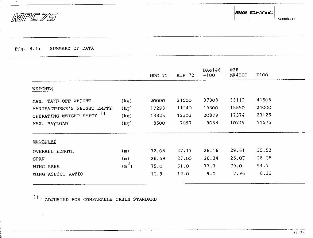
In order to establish another yardstick agalnst which to compare the Baseline Aircraft,some competitors have been analysed. A general survey is given in the figure 8.1 .
Of the competing aircraft considered, only the BAe-146-1OO and the F28 MK4OOO are reallyin the same class äs MPC 75; of these two types the F28-4OOO is no longer in production.The ATR 72 is a smaller aircraft using turboprop engines. It is offered with a ränge of1500 nm: however, this aircraft is not really suited for such ranges because of its lowflight altitude (hence poor ride comfort) and low cruise speed. On the other hand, the F100is a much bigger aircraft than MPC 75.
For the comparison, all aircraft considered were brought to the same Standards äs best äswas possible on the basis of the Information available. Thus, genuine comparability wasensured with respect to the most relevant parameters like seat pitch and hence number ofpassengers, cabin layout, specific cargo volume, weights and mission data such äs speeds,altitude, reserves etc.
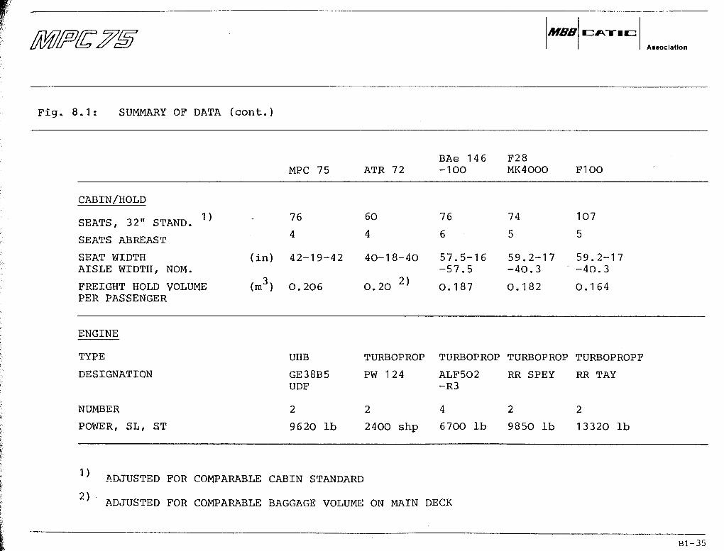
Attention is drawn to the data on seat width/aisle width. The MPC 75 clearly provides abetter Standard than all competing aircraft.
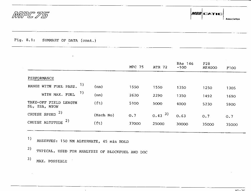
The MPC 75 offers good ränge, high speed (BAe-146 often is criticized for being too slow!)and high cruise altitude. The field performance corresponds to current Standards, with onlythe 4-engines BAe-146 offering significant advantages in this one respect. Finally, theMPC 75 combines good comfort and performance with good economics, äs can be seen fromChapter 9.
Bl-33
MBBAsBocIatlon
Fig. 8.1: SUMMARY OF DATA
WEIGHTSj
MAX. TAKE-OFF WEICHT
MANUFACTURER'S WEIGHT EMPTY
QPERATING WEIGHT EMPTY 1
MAX. PAYLOAD
GEOMETRY
OVERALL LENGTH
SPAN
WING AREA
WING ASPECT RATIO
(kg)(kg)
(kg)
(kg)
(m)
(m)
(m2)
MPC 75
30000
17293
18825
8500
32.05
28.59
75.0
10.9
ATR 72
21500
11040
123O3
7097
27.17
27.05
61 .0
12.0
BAe146-100
37308
19300
20879
9058
26.16
26.34
77.3
9.0
F28MK4000
33112
15850
17374
10749
29.61
25.07
79.0
7.96
F1OO
41505
21OOO
23125
11575
35.53
28.08
94.7
8.33
1) ADJUSTED FOR COMPARABLE CABIN STANDARD
Bl-34
MBBAaaociatlon
Fig. 8.1: SUMMARY OF DATA (cont.)
CABJCN/HOLD
SEATS, 32" STAND. 1 '
SEATS ABREAST
SEAT WIDTHAISLE WIDTH, NOM.
FREIGHT HOLD VOLUMEPER PASSENGER
ENGINE
TYPE
DESIGNATION
NUMBER
POWER, SL, ST
MPC 75
76
4
(in) 42-19-42
(m3) 0.206
UHB
GE38B5UDF
2
9620 Ib
BAe 146ATR 72 -100
60 76
4 6
40-18-40 57.5-16-57.5
0.20 2) 0.187
TURBOPROP TURBOPROP
PW 124 ALF502-R3
2 4
2400 shp 670O Ib
F28MK4000
74
5
59.2-17-40.3
0.182
TURBOPROP
RR SPEY
2
9850 Ib
F1OO
107
5
59.2-1-40.3
0.164
7
TURBOPROPF
RR TAY
2
13320 Ib
1)2)
ADJUSTED FOR COMPARABLE CABIN STANDARD
ADJUSTED FOR COMPARABLE BAGGAGE VOLUME ON MAIN DECK
Bl-35
Associatlon
Fig. 8 . 1 : SUMMARY OF DATA (cont. )
BAe 146MPC 75 ATR 72 -1OO
PERFORMANCE
RANGE WITH FUEL PASS. 1) (nm) 1550 1550 1350
WITH MAX. FUEL 1) (nm) 262O 2290 1350
TAKE-OFF FIELD LENGTH (ft) 5100 5000 4000SL, ISA, MTOtf
CRUISE SPEED 2) (Mach No) 0.7 O. 43 3) 0.63
CRUISE ALTITUDE 2) (ft) 37000 25000 30000
^ RESERVES: 150 NM ALTERNATE, 45 min HOLD
2) TYPICAL, USED FOR ANALYSIS OF BLOCKFUEL AND DOC
3) MAX. POSSIBLE
F28MK4OOO F100
1250 1305
1492 1690
5230 5900
0.7 0.7
35000 35000
Bl-36

MBBAaaoclatlon
9. ECONOMICS
The MPC 75, wlth GE 38 B5-UDF engines and other advanced technology features incorporated,offers advanced economics:
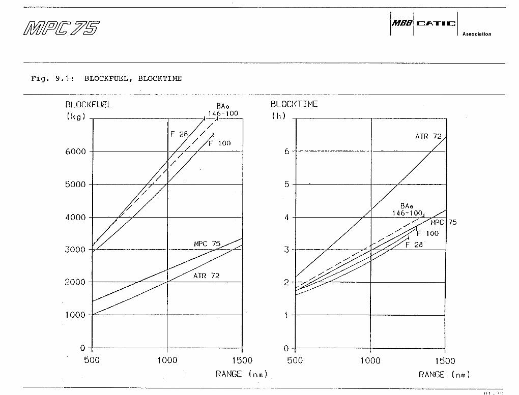
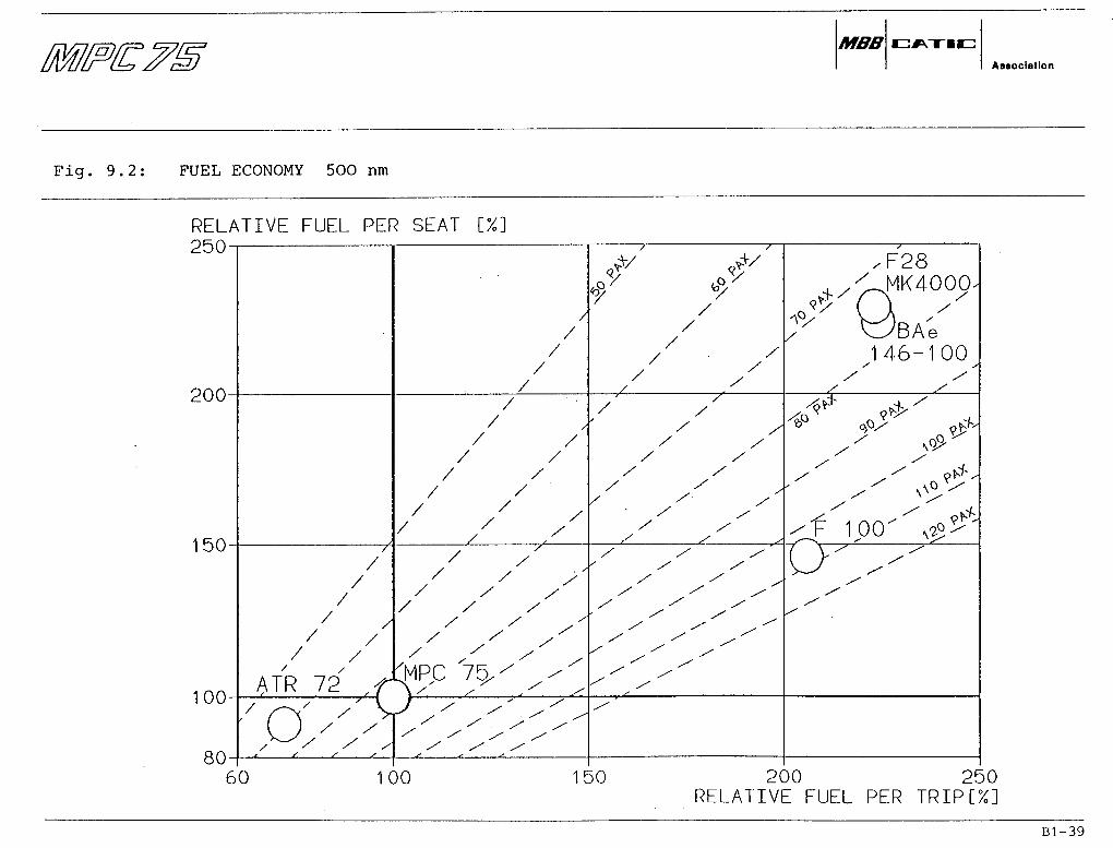
• The MPC 75 combines the advantages of jet speed (like F-28, F-100) with the fueleconomy of propeller aircraft (like ATR-72). See Fig.: 9.1; 9.2; 9.3
• The MPC 75 has lower direct operating cost (DOC) than thät of competitor aircraftwith the same level of passenger seating.
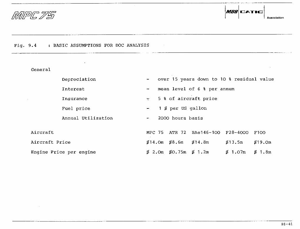
DOC has been calculated using the agreed CATIC/MBB method. Basic input data and assump-tions are given in Fig. 9.4. Results are shown in Fig. 9.5, 9.6 for 500 nm and 100O nmcases. It can be seen that the DOC per seatmile of MPC 75 is
18 % better than that of the BAe-146
7 % better than that of the F-28, andi
5 % better than that of the ATR-72 at 500 nm, with the DOC advantage increasingeven more for the longer stage lengths. MPC 75 also meets the design target ofseatmile cost at least equal to F1OO with 100 passengers.
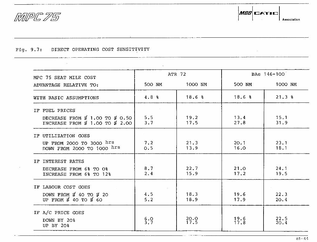
• If economic conditions, such äs fuel prices, utilization, interest rates, labourcost or aircraft price are changed, the DOC of the MPC 75 is still relativelybetter than the competitor aircraft, see Fig. 9.7.
Bl-37
MBBAssoclation
Fig. 9.1: BLOCKFUEL, BLOCKTIME
BLOCKFUCL
( K g )
6000
5000
4000
3000
2000
1000
0
500
MPC 75.
ATR 72
1000
BLOCKTIME
(h)
1500
RANGE (nm)
500 1000 1500
RANGE (nm)
MBBAsaoclatlon
Fig. 9 .2 : FUEL ECONOMY 500 nm
RELATIVE FUEL PER SEAT [%]ORP><1Ö(J
or\r>-<<iUU
1 RAl OU
1 c\r\ UU
AO
A TR 12 /(
, / S s
/
' /
/ / X/ x x
/^ x^ /X
CMP,C 'i^'s^
'/'S^'
/ /
/
// X
^
x /xX X
X X
''•//X /
x x x/ X X
X' X' Xx x x
X X ^
X ^/ ^^
/F28^ MK4000'
v-^ /~\
146-100X X
X X/ x
/ x
„S* \
' /'X
ou60 100 150 200 250
RELATIVE FUEL PER TRIP[%]
Bl-39

MBBAssoclatlon
Fig. 9 .3 : FUEL ECONOMY 100O nm
RELATIVE FUEL PER SEAT [%] _250-i
200-
150-
100-
80-
/ N
/
' /
ATR 72// / X /^>
//
,'
/
// /'
/ / // '
/ / //,/ ^^ / /Mr L^ / Ox -"''
/ ( ) *T\'' s' ^ // /N" — x v y ^ s'' -^/ /^ / l ^ ^ -^ / ^
/ / / A ^^ ^-^ ^/ / S S 1 ^ * ^-l
j, ^/ F 28 MK4000VJ
//
// /
X x/ // X' /
x xxX X
x /X / ^-
X X X^ X X
x x^"" -^
^ ^^ ^^^ ^
^ -S"^ '
0<?^xX CJxX
x°X BAe1 A-(~\~~ \Ox x
x xX X
^^ 4& xxx^ v0>?>^
/ ' 9 1 x
/ F 1 00 o^
O x k^ -^x^ \
x X ^"X* j-
-^^
60 100 150 200 250RELATIVE FUEL PER TRIP[%]
Bl-40
MBBAsaociatlon
Fig. 9.4 : BASIC ASSUMPTIONS FOR DOC ANALYSIS
General
Depreciation
Interest
Insurance
Fuel price
Annual Utilization
Aircraft
Aircraft Price
Engine Price per engine
over 15 years down to 10 % residual value
mean level of 6 % per annum
- 5 % of aircraft price
1 % per US gallon
20OO hours basis
MPC 75 ATR 72 BAe146-100 F28-4000 F1OO
#14.Om $8.6m #14.8m $13.5m $19.Om
$ 2.0m #0.75m $ 1.2m $ 1.07m $ 1.8m
Bl-41

MBBAssoclatlon
Fig. 9.5: DIRECT OPERATING COST 500 nm
RELATIVE COST PER SEAT MILE [%]130
120
1 10
00
90
80
*°/X
<?/
/
,
//
/
O/' ATR 72
xx
XX
/
<PX
i XX
XX
XX
X
xX
XX
X /
s
s
XX
XX
/
^i\/i o r / 'S xX
x \ /x V
XX
Xs-
CATIC/MBB METHODFUEL PRICE 1$/US GAL
XX
_/X
X
/ /"
^xxX
XX
X
uBAe 146
Xx'
MK4000
x
x
X
/x
x-
^^^^
^^
X
xX
XX
X
/
/x-'
X
^^
«P xX
xX
XX
XX
X
NO V
— x^*
1 ^
'QX--x-
jS*
^-^^
80 90 100 10 120 130 140RELATIVE COST PER AIRCRAFT MILE [%]
Bl-42

MBBAssoclation
Fig. 9.6: DIRECT OPERATING COST 1000 nm
RELATIVE COST PER SEAT MILE [%]130
120
10
00
90
80
J/
/
/
X
-"
v?
D/ ATR 72
xxx
X
xx CX
XX
x-
CATIC/MBB METHODFUEL PRICE 1S/US GAL
X'
/
x OF 2J
MPC-75 /'
J x'
X
X
XX
X
x'X
3 MK4000x
^x
X"
XX
XX
XX
X
BAe 146
O /xX
XX
X
X
X
XX
X
/A.
_,s^
^^
^^
X
XX
90 x'X
XX
X
XX"
Xx\F i o o ^ / -
^
80 90 00 110 120 130 140RELATIVE COST PER•AIRCRAFT MILE [%]
Bl-43
MBBAssociation
Fig. 9.7: DIRECT OPERATING COST SENSITIVITY
MPC 75 SEAT MILE COST
ADVANTAGE RELATIVE TO:
WTTH BASIC ASSUMPTIONS
IF FUEL PRICES
DECREASE FROM i 1 . 00 TO # O . 50INCREASE FROM £ 1 .00 TO # 2.OO
IF UTILIZATION GOES
UP FROM 2000 TO 3OOO hrsDOWN FROM 2000 TO 1OOO hrs
IF INTEREST RATES
DECREASE FROM 6% TO 0%INCREASE FROM 6% TO 12%
IF LABOUR COST GOES
DOWN FROM Sf 40 TO $ 20UP FROM i 40 TO i 60
IF A/C PRICE GOES
DOWN BY 20%UP BY 20%
ATR 72
500 NM 1OOO NM
4.8 %
5.53.7
7.20.5
8.72.4
4.55.2
6.03.7
18.6 %
19.217.5
21.313.9
22.715.9
18.318.9
20.017.5
BAe 146-100
500 NM 1000 NM
18.6 %
13.427.8
20.116.0
21 .017.2
19.617.9
19.617.8
21.3%
15.131 .9
23.118.1
24.119.5
22.320.4
22.520.4
Bl-44

MBBAstoclation
10. CONCLUSIONS
General
Working on MPC 75 configuration development in the Feasibility Study Phase, engineers fromMBB and CATIC have cooperated effectively, despite the large distance and partially inade-quate communication lines. The way of working proved to be adequate for the FeasibilityStudy Phase, but a more intensive and more integrated way of working together will becomenecessary when the programme progresses into the Pre-Development Phase.
Requirements
Market needs äs seen today lead to realistic and feasible technical requirements. The per-formance level specified is in general similar to current aircraft, while improvements arerequired wlth regard to design ränge, cabin comfort level and - of course - economics. MoreInformation from potential customers is required to establish a practical and definitiveset of design requirements.
Advanced Technologies
Various new technologies not yet utilized in current regional aircraft are either state-ofthe-art today, or there is well-founded confidence that such technologies can be realizedwithin the time frame of the MPC 75. It is expected that such technologies will signifi-cantly contribute to the competitivity of MPC 75. A preliminary selection of advancedtechnologies and Systems has been made after checking their technical Status. However,further analysis and research work is required for the final selection in view of the strin-gent criteria for MPC 75.
Engine Choice
The GE38 UDF appears to be the best choice for the propulsion of MPC 75, äs it is in theright thrust class for the Baseline Aircraft and offers advantages in terms of weight anddimensions relative to the higher-thrust PW-Allison 501-M80E propfan engine.
Bl-45

MBBAssoclatlon
CONCLUSIONS
The time schedule for the GE38 UDF roughly matches the development programme of MPC 75.The actual availability of the engine is not yet ensured; however, events during the lastyears have greatly enhanced the prospect.
Baseline Conflguratlon
A baseline conf iguration was defined which raeets the design requirements . It will not bethe final solution, but is only the starting point for further refinement and optimizationPerformance analysis and comparison of current regional aircraft show that the MPC 75 Baseline Conf iguration is very competitive in terms of speed, cruise altitüde, comfort, andfuel consumption. In fact, it combines the speed of a Jet aircraft with the fuel savingcharacteristics of a propeller aircraft. ,
75 offers distinct Direct Operating Cost advantages relative to known competitors.Sensitivity analysis shows that this advantage is maintained even under widely varyingeconomic conditions,-
A first study shows that there is a Stretch capability up to approx. 100 seats, but onlyäs a long-term development consistent with the future thrust growth capability of the GE38UDF.
Need for further Activities
Conftrmation or modif ication of the requirements through direct contact with potentialcustomers is urgently required. There is the need for continuing refinement and optimi-zation of the Baseline Conf iguration, for trade-offs, and analysis of alternative Solutions,The analysis and research work related to advanced technologies and Systems must go on.The dialogue with the engine manuf acturers must be kept up and even be intensified, äsengine availability largely depends upon the credibility of the MPC 75 project.
Bl-46

MBBAssoclatlon
CONCLUSIONS
Reconuoendatjon
It ig suggested that the jolnt englneering activitles of CATIC and MBB are continued,to lead over ±nto the Pre-development Phase without slow-down or Interruption.
Bi-47
MBBAssoclation
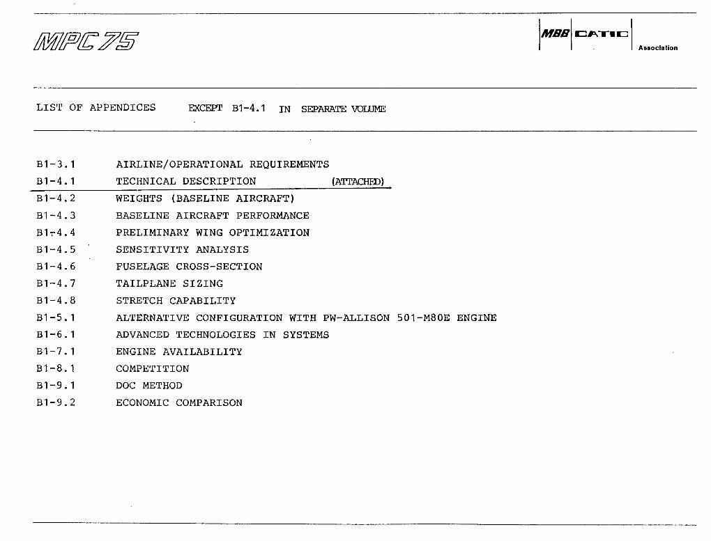
LIST OF APPENDICES EXCEPT B1-4.1 IN SEPARATE VOLUME
B1-3.1
B1-4.1
AIRLINE/OPERATIONAL REQUIREMENTS
TECHNICAL DESCRIPTION (ATTACHED)
B1-4.2
B1-4.3
Blr4.4
B1-4.5
B1-4.6
B1-4.7
B1-4.8
B1-5.1
B1-6. 1
B1-7.1
Bl-8.1
B1-9.1
B1-9.2
WEIGHTS (BASELINE AIRCRAFT)
BASELINE AIRCRAFT PERFORMANCE
PRELIMINARY WING OPTIMIZATION
SENSITIVITY ANALYSIS
FUSELAGE CROSS-SECTION
TAILPLANE SIZING
STRETCH CAPABILITY
ALTERNATIVE CONFIGURATION WITH PW-ALLISON 501-M80E ENGINE
ADVANCED TECHNOLOGIES IN SYSTEMS
ENGINE AVAILABILITY
COMPETITION
DOC METHOD
ECONOMIC COMPARISON

MBBAssoclatlon
APPENDIX: Bl-4,1
SUBJECT : TECHNICAL DESCRIPTION(BASELINE AIRCRAFT)
GROUP Bl "PROJECT DEFINITION"

TT
0 0 0 0 0 0 0 0 0 0 0 0 0 0 0 0 0 0 0 0 0 0 0 0 0 0 0 0 0 0
A —El

MPC - 75 Technical DescriptionDoc.No: TE 154-31/87
Page : iiDate : 25.6.87Revision: -0-
CONTENTS
1.
2.
3.3.3.
3.3.3.3.
4.4.4.
0 Intpoduction
0 Development Schedule
0 Leading Particulars1 GeneralArrangement .2 Dimensions3.2.1 Main Data3.2.2 Wing3.2.3 Fuselage3.2.4 Tailplane3.2.5 Vertical Fin3.2.6 Nacelle3.2.7 Cargo Compartment3 Weights Summary4 C.G. Diagram5 Design Speeds6 Performance Summary3.6.1 Take-off Weight vs. Take-Off Field Length3.6.2 Take-Off Field Length vs. Stage Distance3.6.3 Landin g Weight vs. Landing Distance3.6.4 AircraftCeilings3.6.5 Climb & Cruise Mach Number vs. Altitude3.6.6 Block Fuel vs. Stage Distance3.6.7 Block Time vs. Stage Distance3.6.8 Payload/Range Diagram
0 Aircpaft Description1 GeneralArrangement2 Power Plant
1
3
5556667789
10111213141516171819
202020
MPC 75 Technical Description

MPC - 75 Technical DescriptionDoc.No: TE 154-31/87
Page : iiiDate : 25.6.87Revision: -0-
444
4.4.4.4.
4.4.
4.4.
34564.784 .4.910
2.1 Main Data . . .2.2 Engine Control2.3 Engine MaintenanceFüg h t Deck . . . .Passenger Cabin . .Gargo/Baggage holdsFuselage
6.1 Engine Pylons.Win gTail
8.1 Fin and Rudder8.2 Horizontal tailLandingGear . . . ,Ground Handling . ,
5.05. l5.25.35.45.55.65.75.85.95. 105.115. 12.
5.13
Systems (in ATA Chapter order)Air Conditioning System (ATA21)Automatic Flight Control System - AFCS (ATA 22)Communications (ATA23)Electrical Power (ATA 24)Fire Protection (ATA 26)Flight Controls (ATA 27)Fuel System (ATA 28)Hydraulic Power (ATA 29)Ice and Rain Protection incl. Cleaning (ATACockpit and Instruments (ATA 31) . . . .Landing Gear (ATA 32)Navigation (ATA 34)Pneumatic System (ATA 36)Airborne Auxiliary Power (ATA 49) . . .
30)
2125283233384042424848485055
585862656668707274777983848789
MPC 75 Technical Description
MPC 75 Techniccil DescriptionDoc.No: TE 154-31/87
Page : lDate : 25.6.87Revision: -0-
1.0 INTRODUCTTON
The MPC 75 is designed äs an advanced RegionalP i t c h over a desigri ränge of 1500 n m »initial cruise altitude of not less thanany other aircraft in its category. e.g
aircraft to carry 76flying at a cruise speed of35000 ft. and achieving seat
BAe 146, F28-4000, ATR 72,
passengers at 32 inchM=0.7 to M=0.75, at anmile costs better thanetc .
Prime objectives that have been considered in the design are:-
SafetyReliabilityEnvironmental CompatibilityFlexibilityPassenger AppealStructural SimplicityAdvanced Technology ConceptsLow Fuel Consumption ,Economical OperationStretch Capability
Detailed requirements and objectives are given in a separate note.
The MPC 75 is a low wing aircraft with T-tail and two rear-mounted Ultra by-pass engines.The engine currently being studied in tha baseline configuration is the GE 38 B5 UDF.(Othertypes of ultra by-pass engines are under study)
The overall configuration is consistent with the Intention to utilize advanced technologiesin aerodynamics, structures, materials, Systems and propulsion for improved safety, Opera-tion a l capabilities and superior economics.
Introduction

MPC - 75 Technical DescriptionDoc.No: TE 154-31/87
Page : 2Date : 25.6.87Revision: -0-
This document summarizes the characteristics of the MPC 75, the regional passenger transportaircraft currently under study by MBB and CATIC. The aircraft described is the MPC 75"Baseline Configuration" (MPC 75-OQ1-B), a 76-seater aircraft powered by two General Elec-tric GE 38 B5 Unducteti Fan engines.
The MPC 75 configuration has not yet been finalised and the baseline configuration describedin this document represents the current state of configuration development. It will besubject to modification äs a consequence of a continuing process of technical refinementor changes in the requirements of Potential customers. The baseline configuration äs de-scribed is representative of the typical levnl of Performance and economics of such a typeof aircraft/ äs seen today. It will be used äs a point of reference for trade-offs and op-timisation studies, and thus will be the basis for further improvement.
The aircraftFAR36 Stage 3
will be designed in compliance with thenoise level requirements.
FAR Airworthiness Requirements and
Introduction

MPC - 75 Technical DescriptionDoc.No: TE 154-31/87
Page : 3Date : 25.6.87Revision: -0-
2.0 DEVELOPMENT SCHEDULE
The diagram shows the planned Milestones for the HPC 75 up t o entry intoThe filled-out triangles/bars indicate achieved data.
service in 1995.
Timescale and Milestones
MBB/CalicMO.U.
AssociationAgreement
MfiB/GE M.O.U.
PredevelopmentGo-Ahcad
DevelopmentGo-Ahcad
PfoductionGo-Ahcad
S * "oP 01 t
FirstFligM
E.I.S.
1985
A198G
A
AK$ras******
1987
133
/
1988
^jf
1909 1990
A
X"
1991
.S^
1992
L
1993
\ X '
1994
A
1995
A
1996
Development Schedule
MPC - 75 Technical DescriptionDoc.No: TE 154-31/87
Page : 4Date : 25.6.87Revision: -0-
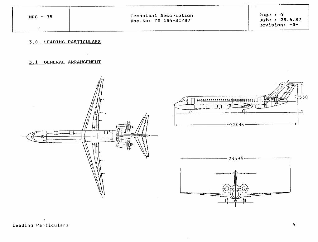
3.0 LEADING PARTICULARS
3.1 GENERAL ARRANGEMENT
[ 00000000000 000000 QjQ 00 po QOOOOQO [ 7550
-32046.
28594-
L e a d i n g P a r t i c u l a r s
MPC - 75 Technical DescriptionDoc.No: TE 154-31/87
Page : 5Date : 25.6.87Revision: -0-
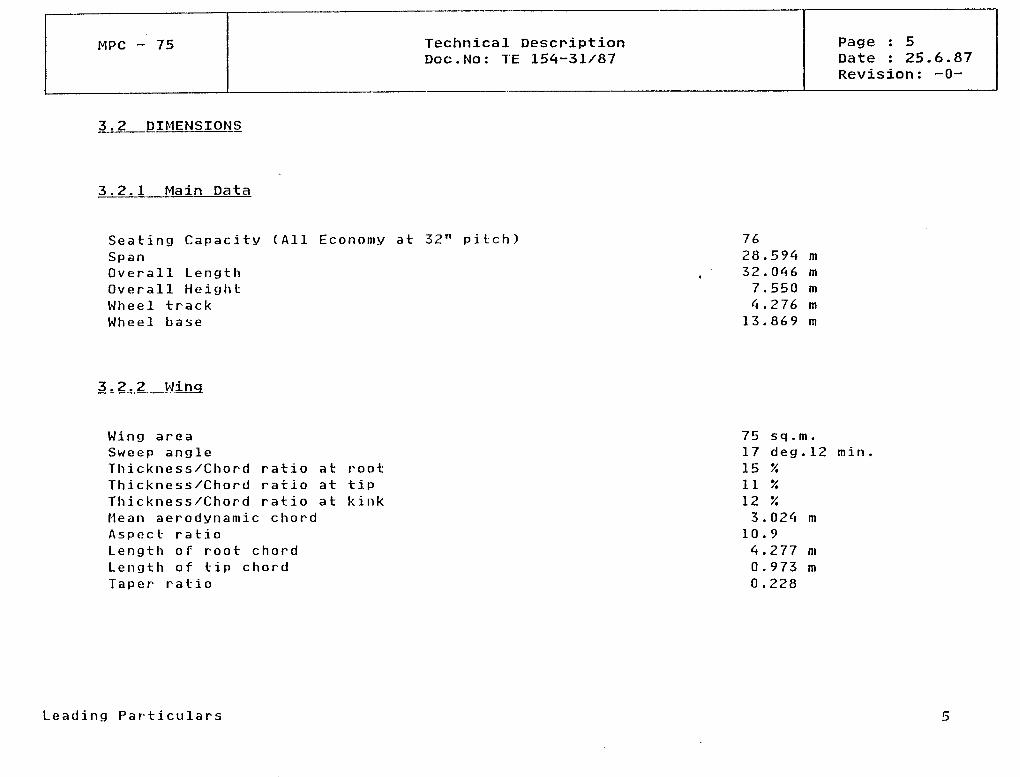
3.2 DIMENSIONS
3.2.1 Ma i n Data
Seating Capacity (All Economy at 32" pitch)SpanOverall LengthOverall HeightWheel trackWheel base
7628.594 m32.046 m7.550 m4.276 m13.869 m
3.2.2 Hing
Wing areaSweep angleThickness/Chord ratio atThickness/Chord ratio atThickness/Chord ratio atMean aerodynamic chordAspect ratioLength of root chordLength of tip chordTaper ratio
roottipkink
75 sq.m.17 deg.12 min15 '/.11 %12 %3.024 m10.94.277 m0.973 m0.228
Leading Particulars
MPC - 75 Technical DescriptionDoc.No: TE 154-31/87
Page : 6Date : 25.6.87Revision: -0-
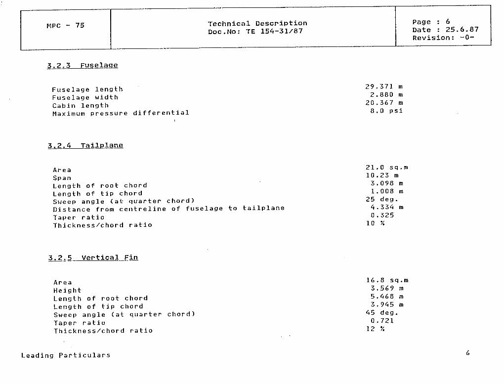
3.2.3 Fuselage
Fuselage lengthFuselage widthGabin lengthMaximum pressure differential
29.371 m2.880 m20.367 m8.0 psi
3.2,4 Tailplane
AreaSpanLength of root chordLength of tip chordSv/eep angle (at quarter chord)Distance from centreline of fuselageTaper ratioThickness/chord ratio
to tailplane
21.0 sq.m10.23 m3.098 ml.008 m
25 deg.4.334 m0.325
10 '/.
3.2.5 Vertical Fin
AreaHeightLength of root chordLength of tip chordSweep angle (at quarterTaper ratioThickness/chord ratio
chord)
16.8 sq.m3.569 m5.468 m3.945 m
45 deg .0.721
12 %
Leading Particulars
MPC - 75 Technical DescriptionDoc.No: TE 154-31/87
Page : 7Date : 25.6.87Revision: -0-
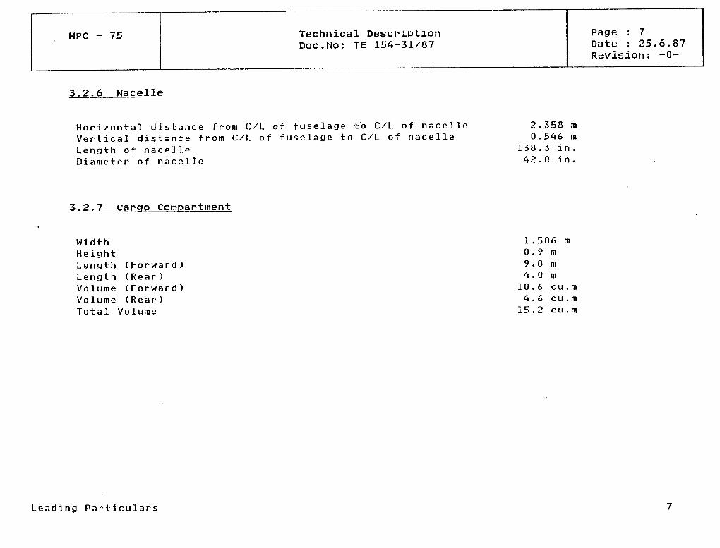
3.2.6 Nacelle
Horizontal distance from C/L of fuselage to C/L of nacelleVertical distance from C/L of fuselage to C/L of nacelleLength of nacelleDianieter of nacelle
2.358 m0.546 m
138.3 in.42.0 in.
3.2.7 Capgo Compartment
WidthHeightLengthLengthVolumeVolumeTotal
(Forward)(Rear )(Forward)(Rear)
Volume
l.506 m0.9m9.0 m4.0m10.6 cu.m4.6 cu .m15.2 cu.m
Leading Particulars
MPC - 75 Technical DescriptionDoc.No: TE 154-31/87
Page : 8Date : 25.6.87Revision: -0-
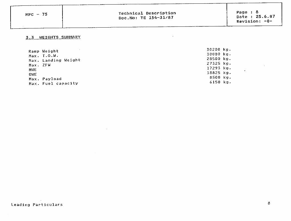
3.3 WEIGHTS SUMMARY
Ramp WeightMaxMaxMaxMWEOWEMax
T.O.W.Landing WeightZFW
PayloadMax. Fuel capacity
30200300002850027325172931882585006150
kg.kg.kg .kg.kg.kg.kg.kg.
Leading Particulars
MPC - 75 Technical DescriptionDoc.No: TE 154-31/87
Page : 9Date : 25.6.87Revision: -0-
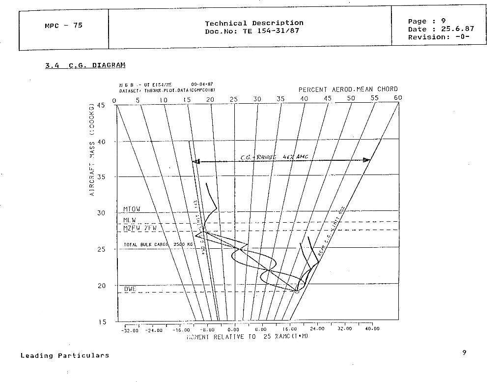
3.4 G.G. DIAGRAM
H G B ,- UT E1C-J/ME 09-04-87D A I A S C T ' TH83NR.PlOT.DArA (CCMPCOIB)
o
ooo
40
z:
v- 35oCK
30
25
20
35PERCENT AEROD.MEAN CHORD40 45 50 55 60
i i i i i r-32.00 -2-1.00 -16 .00 -S.00 0.00 B.00 16 .00
i .JMENT R E L A T I V E TO 25 X A M C ( T * M )
i 1 132.00 40 .00
Leading Part iculars

MPC 75 Technical DescriptionDoc.No: TE 154-31/87
Page : 10Date : 25.6.87Revision: -0-
3.5 DESIGN SPEEDS
VS1VAVBVCMCVDMDVFVNOVMÜMMG
-196210320
0.76380
0.83--350
0.82
kts.kts .kts.kts.Machkts.*Machkts .kts .kts.Mach
*If High Speed Protection is incorporated it would be possible to reduce VD.
Leading Partie ulars 10
MPC - 75 Technical DescriptionDoc.No: TE 154-31/87
Page : 11Date : 25.6.87Revision: -0-
3.6 PERFORMANCE SUMMARY
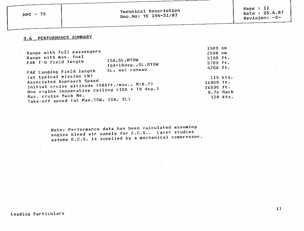
Range with füll passengersRange with max. fuelFAR T-0 field length ISA,SL,MTOW
ISA+18deg.,SL,MTOWSL, wet runwayFAR Landing Field length
(at typical mission LW)Associated Approach SpeedInitial cruise altitude (500ft./min., M=0.7)One engine inoperative ceiling (ISA + 10 deg.)Max. cruise Mach No.Take-off speed (at Max.TOW, ISA, SL)
1500 nm2500 nm5100 ft.5700 ft.4200 ft.
115 kts.36000 ft.16500 ft.0.76 Mach120 kts.
Note: Performance data has been calculated assumingengine bleed air supply for E.G.S.. Later studiesassume E.C.S. is supplied by a mechanical compressor.
Leading Particulars 11

MPC 75 Technical DescriptionDoc.No: TE 154-31/87
Page : 12Date : 25.6.87Revision: -0-
3.6.1 Take-off Weight vs. Take-Off Field Length
32000
30000-
O
28000
20000-
24000
GE3Q UDF1-B59^150 Ib SLST
3000 4000 5000 6000 7000 8000
TOFL (ft)9000 10000 11000 12000
Leading Particulars 12
MPC - 75 Technical DescriptionDoc.No: TE
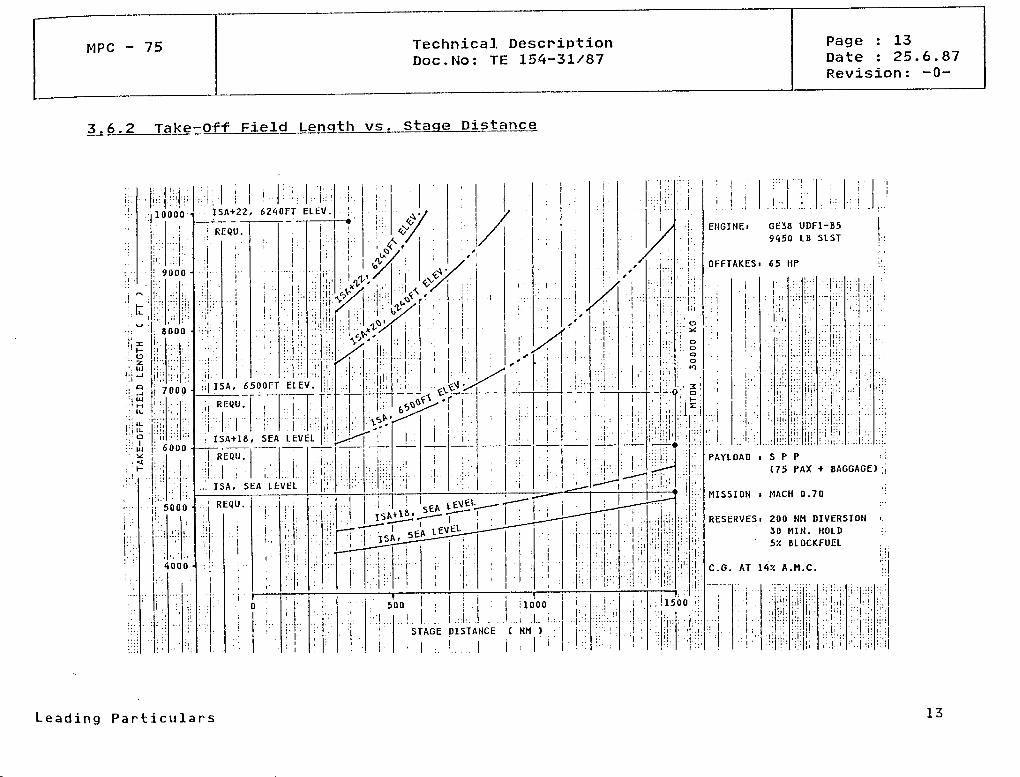
3.6.2 Take-Off Field Lenqth vs .
:i-
. '
•i ~ •:i, t,... w :!i x
.: o... z' • lu
' ' i ~J
MUI
: < c,;; u. •"! D
10 000
!
•V: .:
; 9000 •! : 'i;r, •
r 1 : '
i:!
' ::
. 8000
ii..
l;i • : : ! ;.;
7000
' ':
Üil
.ill
r;: • • :
;j;':'
: ' h-
h'i ;;| : -
iv-1. :
• '
ii"....
. 5000 •
. , : • ..4aon •
i
1 ] ;
i
ISA+22, 6210FT ELEV.
: REQU.
.;;;....
i ; l-' J:1
i:
...ii. :
• . i i . 1 1
: >
, •!
i
i
!
. . . i . .i
;•
• j
1 •
j ' .
,
1 '
|,
: ' : !
ISA, 6500FT ELEV.
;' R,E()U-| ! L--.v
l '!,
1
**{* *
&/ •
V /
%.
!i
, - . . ; • •"l T l 1 ' i 'XN'1
• ISA+18, SEA LEVEL
; REQU.• i V
.]'. ISA, SEA LEVEL
;;
REQU.
' J
,
|
'
',
" ! • 'ii..
.•' •
i >0 i
• !,
;• •
- r -
l
, i! 1
iiil
• ','•
/
•f
;
.. !. .
1 ; ( r •
•
''-.
c\1V-* *
/
^*
W •"
. . . .
i*— -
. . .«'
f ,0? /
/l!i.;:;! '$v.
Ii;:
'|i:1:1.
^ «.
;;:;
/
- • ' . .
h
^
':.•
Staqe
?//<*'/o*/^ -/
: . . .
'
i
"e\&$f£>' 'r
,1 •
. 1 1s^T*rf. '
ii
. .1.i
154-31/87Page : 13Date : 25.6.87Revision: -0-
Distance
'/
,'
•^
SEA U}!
. r-tlPl
^/^
\ •
t
i
EL -T—
j ;
~~ isA. ^Ji r-
..
— — — — "".
.500
1
_- — "
_- '
—• •—
:
'i
' : 1.
.. !
!.t
/s•i • •
. .!
;: ! .
1. . . j . . .
i
1
.,,:.
!i
/
,
,
. — •"" '
. 11
1
1 .. ! :
, '
^— —
1000
„ t.:..
! STAGE DISTANCE ( NM ) ;
l :. .1
!"
1 .
l
i
j
:
' i :
/
//^
-/
i: •
l .1
1
. . . .
;!
^^*
, . '
•
^--
• •
• •
: '
;.:!: n
*•- •"
•
::
'
;-
i •
,— - •• .
^-—
..:, ;.
.".i
: : ' '','.
i-:
,i :•
: • 'Ii i.
'•' l
';i;
'!
ii!i
i* '
• i in' ': .
; '
• i i
iü;' • ; ' :• i ' 1
il'
• 1 '
• ii
I :-'S' O:. o
oo»o
• ' S 1
r
iü:
M '
: '
- •r
J:
:l:
; !1500 <\ : .
: :'!
| 1
. . . ! . . . <;;
1
!...! _
ENGINEt GE38 UDF1-B59150 LB SLST :
OFFTAKESi 65 HP
1
ll.1
! i1 :
• i: •|
• ' , '••
.!".•
•;
; : ':i : ..
J;! ,
| ; 1 1
!i:
- i l >
:r.
Ü-!
:i"!'
, .
• ; .
: 'i .
.1:*
U: '
;;:.
t. i *
1 ! - '
" 1;:"~! "'
1
. ' , . ! : .
- • ; • : ! •::; i'i
... | —
i: , .
.!.: . ',
. ' : . ! .'.
.1 :
• • I I i1
.; i
• - • !
PAYLOAD i S P P -..l
MISSION i MACH 0.70 •
RESERVESi 200 NM DIVERSION i.30 MIN. HOLD -..
C
—
! .
5
G. AT 14X
.1• • i
| .
-r
:|
•/. BLOCKFUEL', ;
A.M.C. i.
,- ...... . .,. . . . : .
ill'
lüi
'.l'::
:•
i:..
l ;
t"
•:
:'•'. ., j
. ' l;i.
r: :.i '
.' '•'• '
'i!i
Leading Particulars 13
MPC - 75 Technical DescpiptionDoc.No: TE 154-31/87
Page : 14Date : 25.6.87Revision: -0-
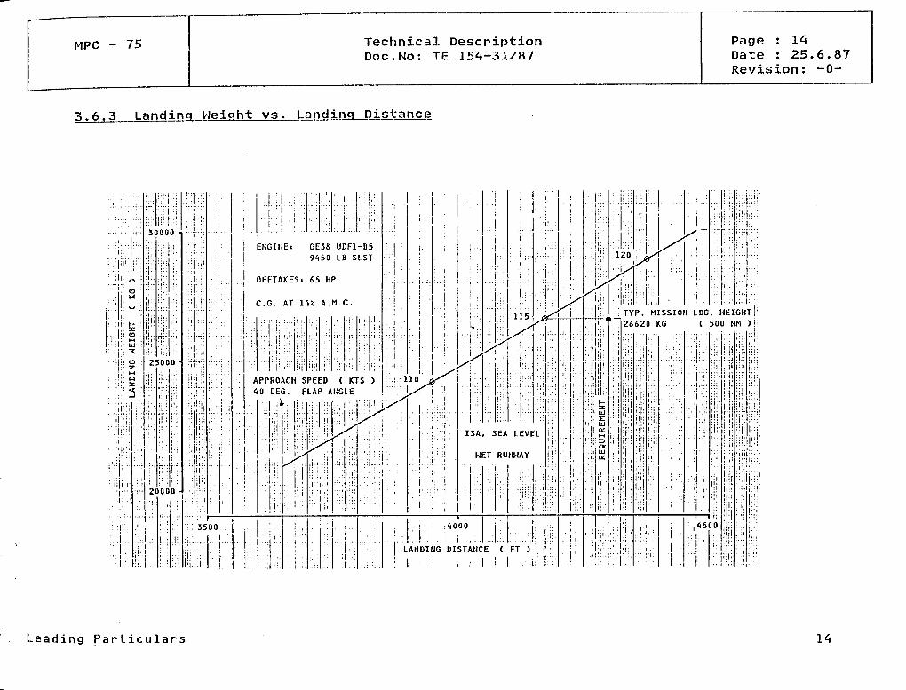
3.6.3 Landing Weight vs. Landing Distance
ENGIHE! GE38 UDF1-B59450 LB SLST
OFFTAKESi 65 HP
C.G. AT \V/. A.M.C.: TYP. MISSION LDG.26620 KG ( 500
APPROACH SPEED ( KTS )10 DEG. FLAP AIJGLE
ISA, SEA LEVEL
WET RUNHAY
LANDING DISTAHCE ( FT )
• i : , ,• l :
Leading Particulars
MPC - 75 Technical DescriptionDoc.No: TE 154-31/87
Page : 15Date : 25.6.87Revision: -0-
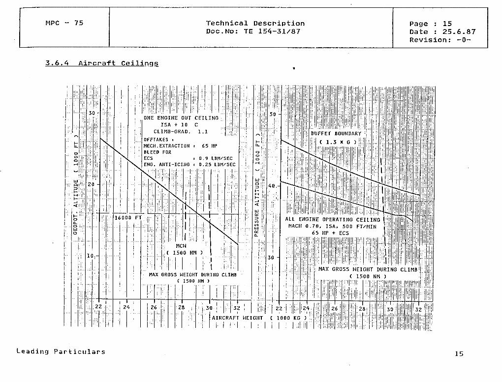
3.6.4 Aircraft Ceilings
i;!:: i
::!i
i i j :I...I.,;.
*->
H
0
• ' •
!;!'
olji '
! ; "-" :!:•" «--t-::
i. ! ji:||| ' - '. .
: j:- «i'!:iZD ' : ; • •
• • p ! J Ü ;j ;|;" ' • • •: ' : ; : ;
!
h- '";o ' • •D. .O 1.::UJ :ca .":
...i :.
: • • .: . : .
• : :
r.i. .
30 -
::..! i.
'!i:
,>'..
::!'':"
• ! 'r:1"
•l
i
20-
l .'
::ii
..L
'!!
.
If
i: :
j-
"t
.! (
ii '
s^
i
:i:
! .
.1
!!;
s
i :
„:.
' I I - :
;
..
;2Z
lüi :|'
S\. ..
1i
1
n1
|
'H( "
l.|( 1
1
i:
1
•
1 i
i,
i
i 1
'i
i'
ui'
j
. ONE ENGINE OUT CEILING
v\
16000
•
•
. i .
: . . .
1
•
. |
'
, . -
N
ISA + 10CLIMB-GRAD.
OFFTAKES iMECH.EXTRACTIOHBLEED FORECSEHG. ANTI-ICING
\
1
1FT
:: . t
'
i
1 '
i .
\\"kIN
l|
1i
MCW
,( 1500ii
c1.1
l,1
'
1!
l'n
i
li
i
i 65 HP
i 0.r 0.
S
l
X
NM )
9 LBM/SEC25 LBM/SEC
111
N~N,
i
S.
1
\
1
|:1
11|
11
Hj '!
1
1
1
|
(
1l
'1
1r
MAX GROSS HEIGHT DURING CLIMB( 1500 NM )
1
' • • •
. ... j....
i 26 , ; :, i 28
:
3 0•• ;
•;;
3.i
i ' 'i
AIR( :RAFIr HEI
50
l:il
li
30
ALL ENGINE OPERATING CEILING |MACH 0.70, ISA, 500 FT/MIN '
65 HP + ECS
MAX GROSS WEICHT DURING CLIMB( 1500 NM )
22 1
( 1000 KG )
i , l :26 !
H!28: 32!
... iIn!
Leading Part iculars 15

MPC - 75 Technical DescriptionDoc.No: TE 154-31/87
Page : 16Date : 25.6.87Revision: -0-
3.6.5 Climb & Cruise Mach Number vs. Altitude
40
35-
Ooo
0)
30
20-
15
500 ft/m n (max. climb thrust)
40
35
c: 30ooo
<DT313
20-
0.650 0.675 0.700 0.725 0.750 0.775 0.80015
Mach-Number0.65
Leading Particulars
ISA, ROCL=
a/c mass (1000kg)
0 ft/min (max. cruise thrust)
—l 1—0.70 0.75
Mach-Number0.80
16

MPC - 75 Technical DescriptionDoc.No: TE 154-31/87
Page : 17Date : 25.6.87Revision: -0-
3.6.6 Block Fuel vs. Stage Distance
STAGE DISTANCE ( HM )l l l l
Leading Particulars 17

MPC - 75 Technical DescriptionDoc.No: TE 154-31/87
Page : 18Date : 25.6.87Revision: -0-
3.6.7 Block Time vs. Stage Distance
ENGINE. GE38 UDF1-B5
9450 LB SLST
STAGE DISTANCE ( NM )
. l . i •
Leading Particulars 18
MPC - 75 Technical DescriptionDoc.No: TE 154-31/87
Page : 19Date : 25.6.87Revision: -0-
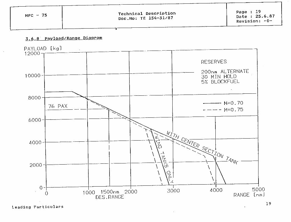
3,6.8 Payload/Range Diagram
PAYLOAD [kg]12000
10000-
8000-
6000-
4000-
2000-
200nm ALTERNATE30 MIN HOLD5% BLOCKFUEL
1000 1500nm 2000DES.RANGE
3000 4000 5000RANGE [nmJ
L e a d i n g Particulars 19
MPC - 75 Technical DescriptionDoc.No: TE 154-31/87
Page : 20Date : 25.6.87Revision: -0-
AIRCRAFT DESCRIPTION
4.1 GENERAL ARRANGEMENT
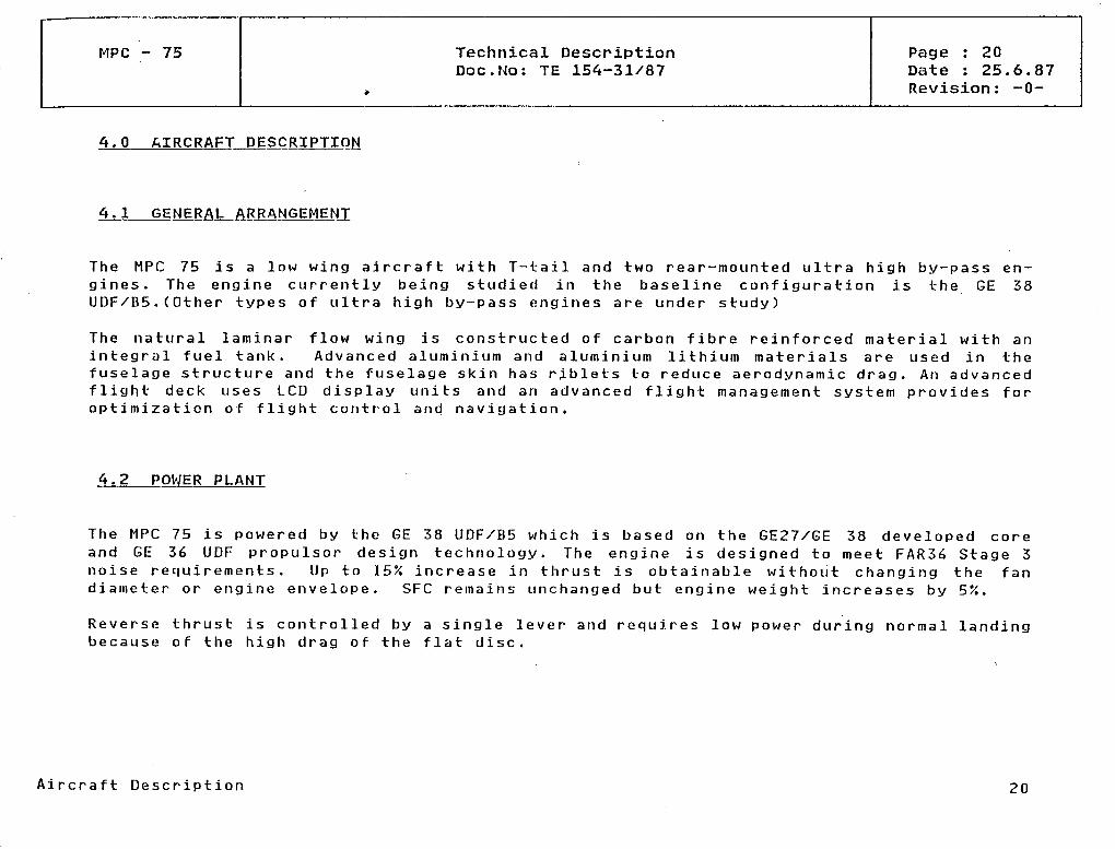
The MPC 75gines. TheUDF/B5.(Other
is a low wing aircraft with T-tail and two rear-mounted ultra high by-pass en-engine currently being studied in the baseline configuration is the GE 38
types of ultra high by-pass engines are under study)
The natural laminar flow wing is constructed of carbon fibre reinforced material with anintegral fuel tank. Advanced aluminium and aluminium lithium materials are used in thefuselage structure and the fuselage skin has riblets to reduce aerodynatnic drag. An advancedflight deck uses LCD display units and an advanced flight management system provides foroptimization of flight control and navigation.
4.2 POWER PLANT
The MPC 75 is powered by the GE 38 UDF/B5 which is based on the GE27/GE 38 developed coreand GE 36 UDF propulsor design technology. The engine is designed to meet FAR36 Stage 3noise requirements. Up to 15% increase in thrust is obtainable without changing the fandiameter or engine envelope. SFC remains unchanged but engine weight increases by 5%.
Reverse thrust is controlled bybecause of the high drag of the
a single leverflat disc .
and requires low power during normal landing
Aircraft Description 20
MPC 75 Technical DescriptionDoc.No: TE 154-31/87
Page : 21Date : 25.6.87Revision: -0-
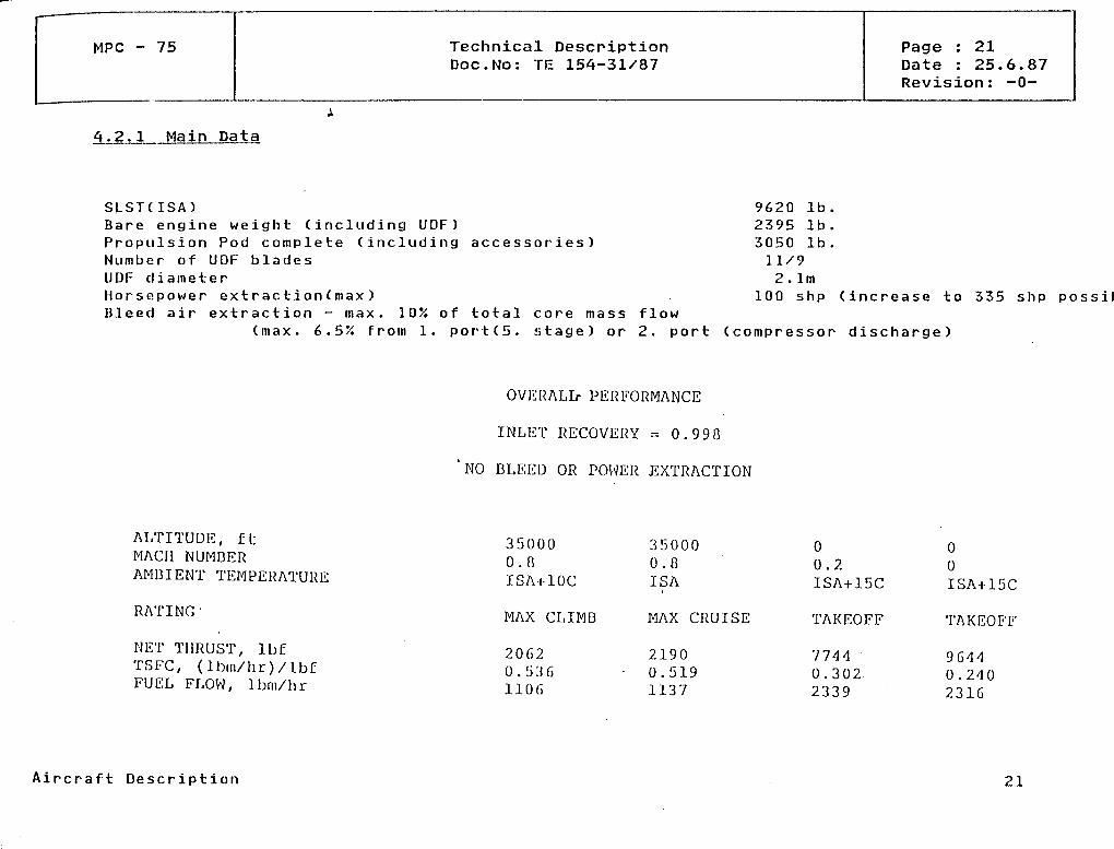
4.2.l Main Data
SLST(ISA)Bare engine w e i g h t (including UDF)Propulsion Pod c o m p l e t e (includingN u m b e r of UDF bladesUDF cliameterHorsepower e x t r a c t i o n ( m a x )Bleed air extraction - max. 10% of
accessories)
total core mass( m a x . 6.5/i froin l. p o r t (5 . s t a g e ) or
f low2. port
9620 Ib2395 Ib3050 Ib11/92. Im
100 shp (increase to 335 shp possible
(compressor d i s c h a r g e )
OVERALL- PERFORMANCE
INLIST RECOVERY = 0.990
'NO DLEED OR POWER EXTRACTION
ALTITUDE, ftMACH NUMBERAMDIENT TEMPERATURE
RATING'
NET THRUST, IbfTSFC, (lbm/hr)/lb£FUEL FLOW, Ibm/hr
350000.0ISAi-lOC
MAX CLIMD
20620.13361106
350000.0ISA
MAX CRUISE
21900.5191137
00.2ISA+15C
TAKEOFF
77440.3022339
00ISA+15C
TAKEOFF
96440.2402316
Aircraft Description 21
MPC - 75 Technical DescriptionDoc.No: TE 154-31/87
Page : 22Date : 25.6.87Revision: -0-
Reverse Ihrust
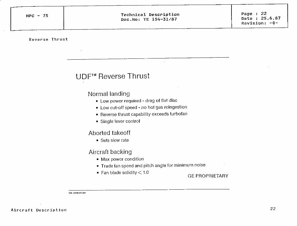
UDF™ Reverse Thrust
Normal landing• Low power required - drag of flat disc
• Low cut-off speed - no hot gas reingestion
• Reverse thrust capability exceeds turbofan
• Single lever control
Aborted takeoff• Sets slew rate
Aircraft backing• Max power condition
• Trade fan speed and pitch angle for minimum noise
• Fan blade solidity < 1.0GE PROPRIETARY
A i r c r a f t Description
MPC - 75 Technical DescriptionDoc.No: TE 154-31/87
Page : 23Date : 25.6.87Revision: -0-
Installation Outline
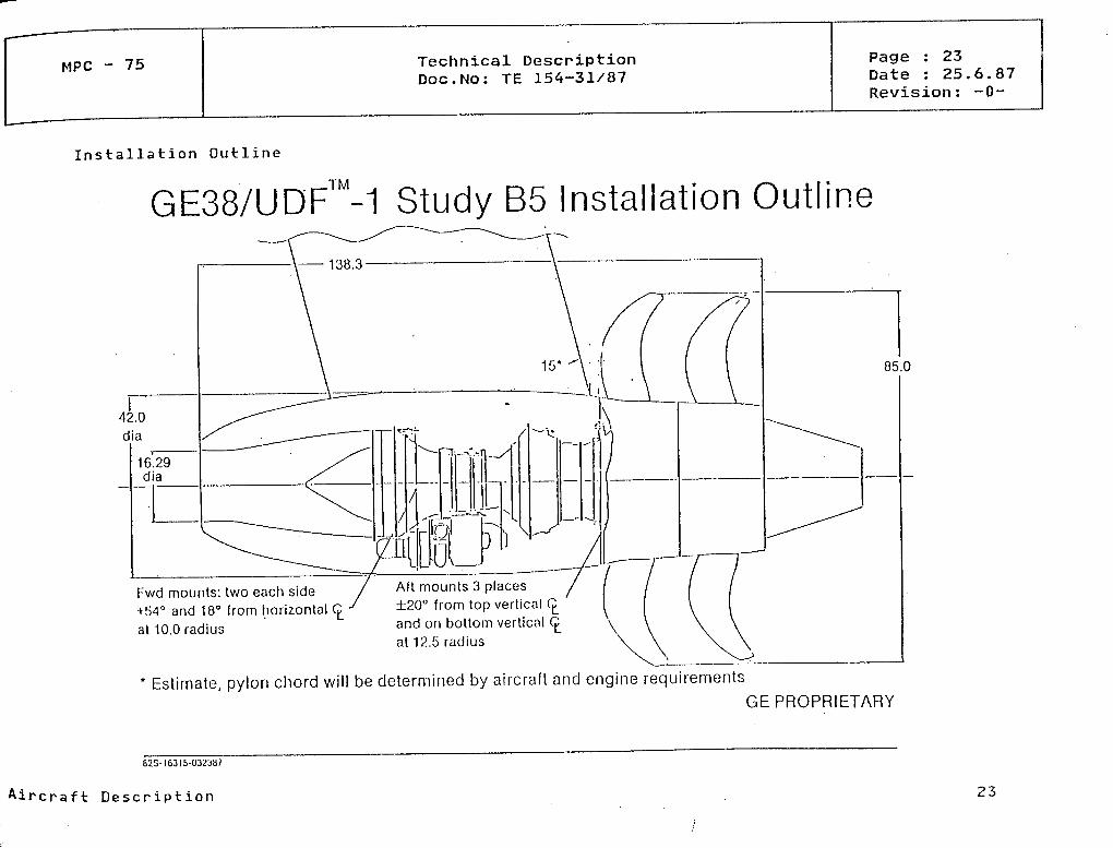
GE38/UDF™-1 Study B5 Installation Outline
85.0
Fwd mounts: two each side+54° and 18° from horizontalat 10.0 radius
Aft mounts 3 places±20° from top vertical CL
and on bottom vertical Cat 12.5 radius
* Estimate, pylon chord will be cletermined by aircraft and engine requirements
GEPROPRIETARY
82S-I6315-032387
Aircraft Description 23

MPC - 75 Technical DescriptionDoc.No: TE 154-31/87
Page : 24Date : 25.6.87Revision: -0-
Pylon A r r a n g e m e n t
Engine atlachbearn assembly
Gasgenerator
Engine mounls
Propulsor
Exhaust cone
S 0095 050508
Aircraft Description 24

MPC 75 Technical DescriptionDoc.No: TE 154-31/87
Page : 25Date : 25.6.87Revision: -0-
4.2.2 Engine Control
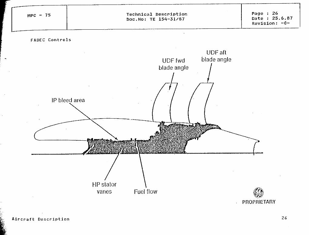
The ennine is controlled by means of FADEC tnounted on the engine in a single housing. FADECuses engine alternator power and has self-test fault detection. Control strategy is shownbelow.
EPR scheduled äs function of PLAFuel flow niodulated to control EPRForward fan RPM scheduled via EPRForward fan blade angle varied to control RPMAft fan blade angle modulated to synchronize/synchrophase with forwardGas generator variable geometry adjusted for core RPM, temperature and
fanpressure
Schematic Control System and FADEC control are shown in diagrams.
Aircraft Description 25
MPC - 75 Technical DescriptionDoc.No: TE 154-31/87
Page : 26Date : 25.6.87Revision: -0-
FADEC Controls
IP bleed area
UDFfwdblade angle
UDFaftblade angle
HP Statorvanes Fuel flow
PROPRIETARY
A i r c r a f t Description 26

MPC - 75
UDF Control Sys tem
Technical DescpiptionDoc.No: TE 154-31/87
Page : 27Date : 25.6.87Revision: -0-
T/OMemory FADEC
MXCLMemory FADEC
Power LovorAngle(PLA)
EPR
FuolController
GagGenoralor
(Power)
Thrust
BladoPoalion
l
PROPRIETARY
iai'J.08-800505
Aircraft Description 27

MPC - 75 Technical DescriptionDoc.No: TE 154-31/87
Page : 28Date : 25.6.87Revision: -0-
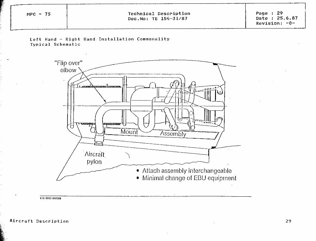
Engine Maintenance
The engineopening theand is made
is connect^d to the pylon by an attachment beam and i s easily removable aftercowls which remain on the pylon. The engine is interchangeable LH and RH sideup of modules äs shown in diagrams.
Aircraft Description 28
MPC - 75 Technical DescriptionDoc.No: TE 154-31/87
Page : 29Date : 25.6.87Revision: -0-
Left Hand - R i g h t Hand Installation C o m m o n a l i t yTypical Schematic
'Flip over"elbow
• Attach assembly interchangeable• Minimal change of EBU equipment
4IS 0093-050586
Aircraft Descripti on 29

MPC - 75 Technical DescriptionDoc.No: TE 154-31/87
Page : 30Date : 25.6.87Revision: -0-
Easy Removal of the Propulsion System
Components remaining with aircraft• Cowls
— Upper— Lower
Demountable units• Basic engine• Inlet and duct• Nacelle equipment
• Attach bearn
Aircraft Description 30
MPC - 75 Technical DescpiptionDoc.No: TE 154-31/87
Page : 31Date : 25.6.87Revision: -0-
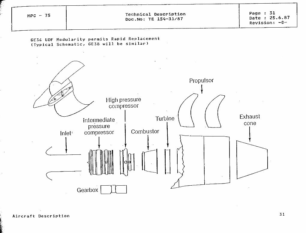
GE36 UDF M o d u l a r i t y p e r m i t s R a p i d R e p l a c e m e n t(Typical Schematic, GE38 will be s i m i l a r )
Inlet1
High pressurecompressor
Intermediatepressure
compressor
Turbine
Combustor
Q
Gearbox
Propulsor
Exhaustcone
A i r c r a f t Description 31
MPC - 75 Technical DescpiptionDoc.No: TE 154-31/87
Page : 32Date : 25.6.87Revision: -0-
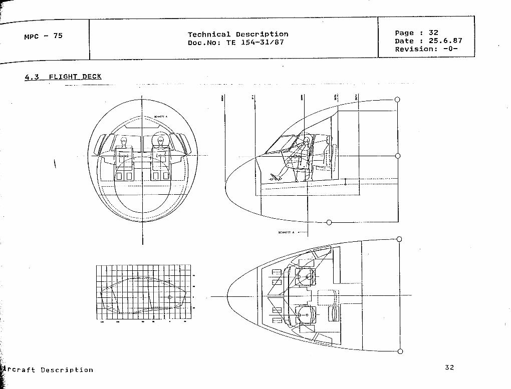
4.3 FLIGHT DECK
O
Lrcraft Description 32
MPC - 75 Technical DescriptionDoc.No: TE 154-31/87
Page : 33Date : 25.6.87Revision: -0-
4.4 PASSENGER CABIN
The upper lobe of the fuselage is dimensioned to provide in a Standard 4-abreast seatingarrangement a more spacious and hence niore comfortable cabin than any other aircraft of theclass.
Cabin access is through passenger doors on the left hand side and Service doors on the righthand side at both the front end and the rear end of the cabin. All entry doors are of thesame size and serve äs Type l emergency exits. According to the JAR and FAR proposed Rulesthese allow a maxinium capacity of up to 90 - 110 passengers. (äs long äs distance betweenfront and rear doors is no greater than 60ft.)
The basic seating arrangement is for 76 Tourist passengers at 32 inch pitch.a 69 seat Mixed Class version with 36"/32" pitch and a high density Versionat 30" pitch. (See diagrams.) Seat rails permit changes in seating pitch increments.
There is alsowith &4 seatsone inch i n -
Galleys and lavatories can be arranged at bothadequate capacity for carry-on baggage.
ends of the cabin. Overhead bins provide
Aircraft Description 33
MPC - 75 Technical DescriptionDoc.No: TE 154-31/87
Page : 34Date : 25.6.87Revision: -0-
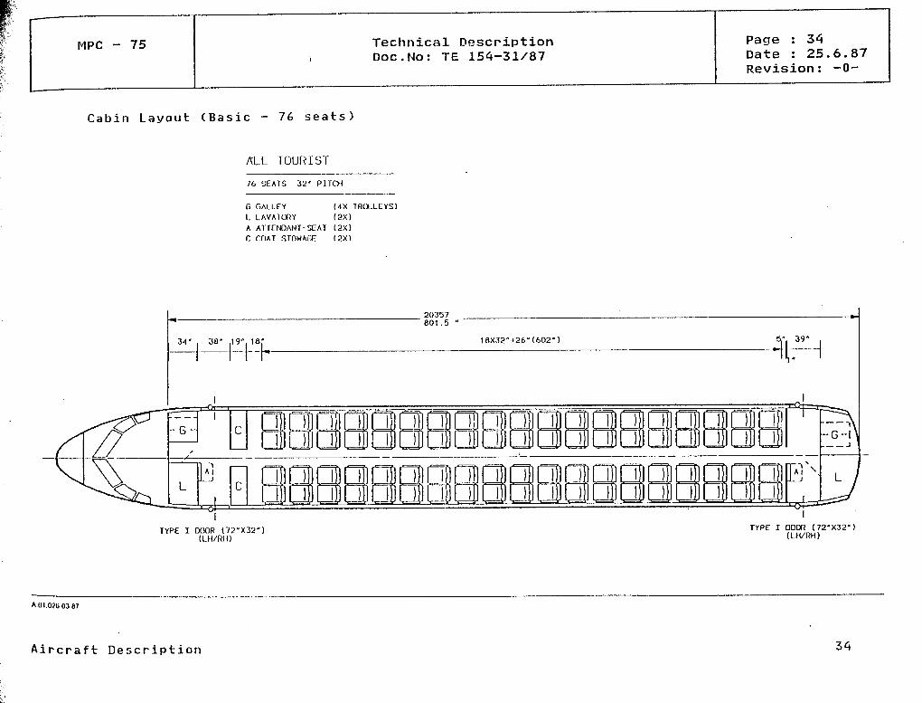
Cabin Layout (Basic - 76 seats)
ALL TOURIST
76 SEATS 32' PITCH
G GALLEY MX TROLLEYS)L LAVATORY (2X)A ATTENDANT-SEAT (2X)r. mAT STOWAGE (2X)
TYPE I DODR (72"X32")(LH/RH)
TYPE I DODR (72-X32-)(LH/RH)
AUI.O?60387
Aircraft Description

MPC - 75 Technical DescriptionDoc.No: TE 154-31/87
Page : 35Date : 25.6.87Revision: -0-
Cabin Layout (Mixed Class - 69 seats)
MIXED CLASS
9 SEATS 36" PITCH60 SEATS 32" PITCH
69 SEATS TOTAL
G GALLEY (5X TROLLEYS)L LAVATORY (SX)
A ATTENDANT-SEAT ( 3 X >C COAT STOVMGE (2X)
TJ* -m- on« 2X36"*27.5" -,. ,ft04 i O" . . £O . * <-.j-i r- * \. . l D
TYPE I DOOR (72-X32")(LH/RH)
TYPE I CXXIR (72"X32")(LH/RH)
A.OI 0270387
Aircraft Description 35

MPC - 75 Technical DescriptionDoc.No: TE 154-31/87
Page : 36Date : 25.6.87Revision: -0-
Cabin Layout (High Density - 80 seats)
HIGH DENSITY
84 SEATS 30 PI1CH
G GALLEY (4X TROLLEYS)
L LAVATORY (2X)A ATTENDANT-SEAT (2X)S STOWAfiE (2X>
34' . 38" J" 18
-G-
20357801 .5
20X30"*26"-626"
o
3-J' 37"
TYPE I OOOR (72"X32")(LH/RH)
TYPE I DOOR (72'X32")(LH/RH)
A.OI.028.03.87
Aircraft Description 36
MPC - 75 Technical DescriptionDoc.No: TE 154-31/87
Page : 37Date : 25.6.87Revision: -0-
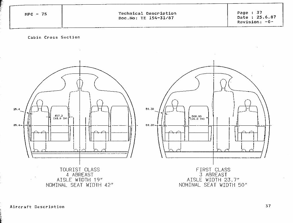
Cabin Cross Section
r25.4
26. 4.
/ ( 'p-L._\
p,,
/ \2, (18.0 IN)
L
J UJ
TOURIST CLASS4 ABREAST
AISLE WIDTH 19"NOMINAL SEAT WIDTH 42"
59.30
59.3O
FIRST CLASS3 ABREAST
AISLE WIDTH 23.7"NOMINAL SEAT WIDTH 50"
A i r c r a f t Description 37
MPC - 75 Technical DescriptionDoc.No: TE 154-31/87
Page : 38Date : 25.6.87Revision: -0-
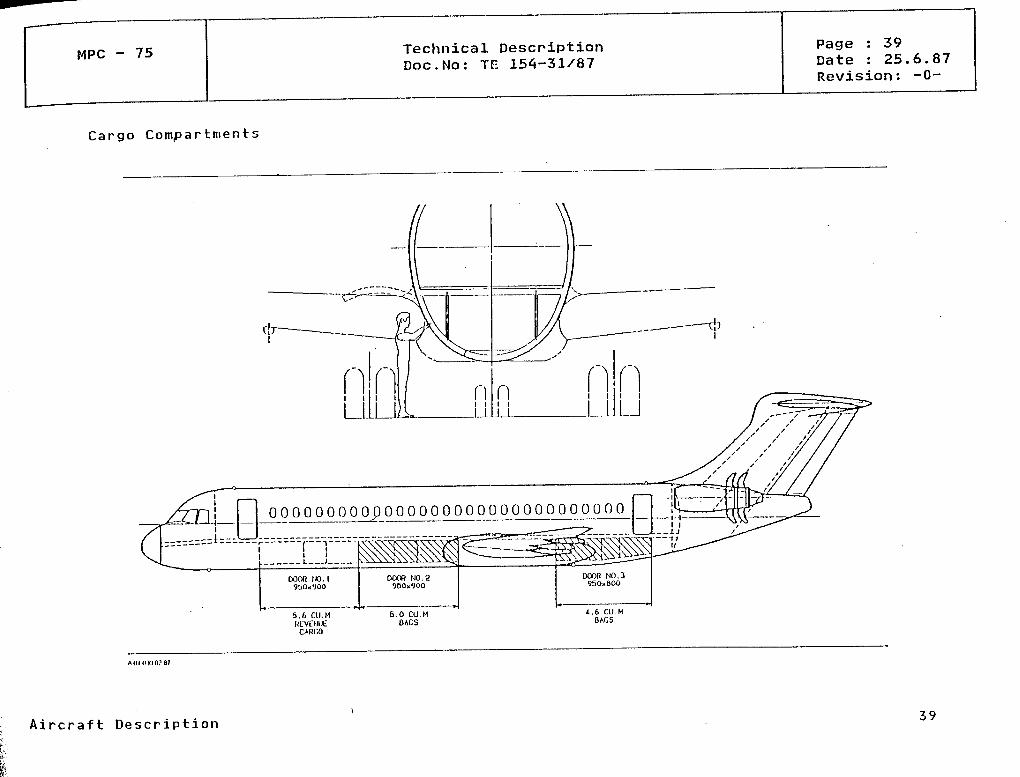
CARGO/BAGGAGE HOLDS
The underfloor cargo hold offers a capacity of 10.6 cu.m. in the forward hold and 4.6 cu.m.in the rear hold. The height of the cargo hold is 900 mm (i.e. 4 inches more than offeredby the closest 5-abreast competitorj.
Manual loading is assumed in the Standard Version. In order to simplify loading, two doors1450 mm x 900 mm are provided in the forward hold. The rear hold has one door with the samedimensions. The cargo holds are equipped with tie-down points and door nets. The front holdhas, in addition, a divider net.
As an Optionforward hold.
a telescopic bin System and a belt loading system may be considered for theIn this case only one door will be necessary in the forward hold.
Aircraft Description 38
MPC - 75 Technical DescriptionDoc.No: TE 154-31/87
Page : 39Date : 25.6.87Revision: -0-
Cargo Compartments
\0
A i r c r a f t D e s c r i p t i o n 39

MPC - 75 Technical DescriptionDoc.No: TE 154-31/87
Page : 40Date : 25.6.87Revision: -0-
4.6 FUSELAGE
The constant-section fuselage has a blended double-bubble cross-section with 2 + 2 abreastseating and a single aisle and offers ample underfloor baggage/cargo volume. The fuselageconstruction is of conventional skin/stringer/frame construction with a typical frame pitchof 20 inches. The nose section has no stringers but a reduced frame pitch.
It is assumed that sandwich type structural elements will be integrated in the tail conestructure.The afterbody structural design will be determined by the noise fatigue require-ments .
Further structural details remain to be defined. Materials have not yet been specified.Selective use will be made of advancecl metals such äs aluminium lithium for passenger andservice doors, stringers, floor structure and window frames. Fairings and access doors andlanding gear doors are in composite material. Floor panels consist of glass fibre.
Aircraft Description 40

MPC - 75 Technical DescriptionDoc.No: TE 154-31/87
Page : 41Date : 25.6.87Revision: -0-
Fuselage Cross Section
3314.5
Aircraft Description

MPC - 75 Technical DescriptionDoc.No: TE 154-31/87
lPage : 42Date : 25.6.87Revision: -0-
4.6.1 Engine Pylons.
The engine pylon structure continues through the rear end of the fuselage. Aluminium lithiumis used for the structure and the fairings are of composite material. Quick attachmentbolts connect with the engine attachment beam and pertnit rapid removal of the engine.
4.7 WING
The quarter chord of the wing MAC is positioned 16657 mm aft of the aircraft nose. Theplan form is matched to the needs of natural laminar flow» i.e. the leading edge sweep islimited to 20 degrees, the wing chords are kept short and aspect ratio is high.
From considerations of the landing gear Installation, the wing trailing edgeapproximately 3 4 /£ semi-span.
is kinked at
The leading edge is fixed. The trailing edge flaps have about Z0% chord outboard of the kinkwhile inboard of the kink, flap chord remains constant equal to that at the kink. Theailerons are positioned outboard of the flaps and there are four spoilers per side, oneinboard and three outboard of the kink.
The wing box is designed to carry fuel outboard of the root rib. Tank capacity is estimatedto be approx. 3100 kg. per side. For developed versions, space is available for more fuelin the centre section. Potential additional capacity is estimated to be approx. 2500 kg.
It is assumed that the major components of the wing are arranged "geometrically conven-tional", i.e. an unswept centre-section box buried in the fuselage and two cantilever sweptoutboard wings attached to each side of the centre-section box. Both the centre-sectionbox and the outboard wing box are of two-spar design. Outboard the kink, both the front andrear spars run at constant chord percentages whereas inboard the kink the spar positionsare at varying chords resulting in a straight front spar and a kinked rear spar.
Aircraft Description
MPC - 75 Technical DescriptionDoc.No: TE 154-31/87
Page : 43Date : 25.6.87Revision: -0-
To ensur,e natural laminar flow, the fixed leading edge structure will be integrated withthe wing box structure in such a way that a smooth surface can be maintained under allconditions. The leading edge thus becomes a part of the primary wing structure. It is de-signed to carry part of the wing loads äs well äs to improve the torsional stiffness of thewing and to withstand bird impact and damage from hail. Provision is made for the instal-lation of an efficient anti-icing System.
The wing structure is manufactured of carbon fibre reinforced material and, where a p p r o -priate, of advanced metals. Details are to be defined.
To provide protection from lightning strikes the composite wing box is covered with a wiremesh System and solid metallic conductors to facilitate current flow. These metallic con-ductors are combined äs far äs possible with such structural necessities äs the rear sparand lower flange. As a further precaution, rivetting through the skin panels is to beavoided äs far äs possible.
As a precaution against corrosion a design target is that all metallic parts inside the fuelcompartment shall be of either titanium or stainless steel.
Type and location of the root panel joints are not yet finally decided. One design understudy provides for only one skin joint located at the fuselage centre line. In all casesthe skin joints are of double-spliced shear-loaded design.
The main landing gear attachment area is not yet decided. Under consideration is a separatemetal beam located behind the rear spar designed and integrated into the rear spar in sucha way that it is capable of withstanding the high loads sustained by the landing gear inthe crash case. The beam box is a single component running through the fuselage.
The wing skins are designed and manufactured äs stringer stiffened integrally monolithicShells. The integrally stiffened front spar web is rivetted to the flanges integrated inthe upper and lower skins during assembly. The rear spar is also designed äs an integrallystiffened web containing one flange for the connection with the lower skin panel.
Aircraft Description
MPC - 75 Technical DescriptionDoc.No: TE 154-31/87
Page : 44Date : 25.6.87Revision: -0-
Three types of ribs will be installed: heavily loaded ribs at load introduction stationse.g. flap t r a c k positions, undercarriage pick-up, etc., supporting ribs and sealing ribsin connection with the fuel tank and venting system. Design and manufacturing techniqueof the ribs will be chosen in accordance with the local requirements.
Aircraft Description 44

MPC - 75 Technical DescriptionDoc.No: TE 154-31/87
Page : 45Date : 25.6.87Revision: -0-
Wing Geometry
75
Aircraft Description

MPC - 75 Technical DescriptionDoc.No: TE 154-31/87
Page : 46Date : 25.6.87Revision: -0-
Key Points for Wing Development
root jointMain landing gear attachment
Stability of stiffened high
loaded she22s (load factor)
Design strain level
jLightning strike protection,
EMC
Fixed leading edge for NLF-Hing
Aeroelastic tailoring for improved performance
Impact tolerant design ( I T D )
Integrated fuel tank
Advanced CFRP material
Aircraft Description 46
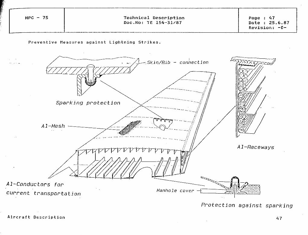
MPC - 75 Technical DescriptionDoc.No: TE 154-31/87
Page : 47Date : 25.6.87Revision: -0-
P r e v e n t i v e M e a s u r e s against L i g h t n i n g Strikes.
Al-Conductors for
current transportation
..Skin/Hib - connection
Sparking protection
Al-Mesh
Al-Raceways
Hanhole covcr —
Protection against sparking
A i r c r a f t Description
MPC - 75 Technical DescriptionDoc.No: TE 154-31/87
Page : 48Date : 25.6.87Revision: -0-
4.8 TAIL
4.8,1 Fin and Ruddep
The MAC quarter chord of the vertical stabilizer is positioned 26803 mm aft of the aircraftnose and 10146 mm aft of the wing MAC quarter chord respectively.
The vertical tail is moderately tapered from consideration of the Installation of the hor-izontal tail at the top. The fin box is of three-spar design with the spars running atconstant chord.
The rudder is split and double hinged at approx. 70% and 85% respectively.
Structurally the fin is integrated with the aft fuselage structure. The fin and rudder areconstructed of carbon fibre reinforced Material. Leading edges are of honeycomb con-struction covered with composite material.
4.8.2 Horizontal tail
The MAC quarter chord of the horizontal stabilizer is positioned 29539 mm aft of the air-craft nose and 12882 mm aft of the wing MAC quarter chord respectively. It is of trimmingtype with a travel ranging u p t o -14 deg.
The main box is a two-spar design with both spars running constant chord. It comprises oftwo swept boxes joined at the centre line. The elevators are hinged at approx. 70% chord.
Structupally the horizontal tail box is attached to the top of the fin box by a hinge aftof the rear spar and the trim actuator attachmment forward of the front spar. The hori-
Aircraft Description 48
MPC - 75 Technical DescriptionDoc.No: TE 154-31/87
Page : 49Date : 25.6.87Revision: -0-
z o n t a l tail is constructed o f c a r b o n fibre reinforced materialhoneycomb construction covered with composite material.
Leading edges are of
Aircraft Description
MPC - 75 Technical DescriptionDoc.No: TE 154-31/87
Page : 50Date : 25.6.87Revision: -0-
4 . 9 LANDING_GEAR
The MPC 75 aircraft configuration calls for a main landing gear at 71% AMC on the groundwith sideways retraction and dual wheels. A slight inboard inclination angle of the mainlanding gear leg and skewed trunnions supported by structure aft of the rear wing sparpermits stowage of the main landing gear with a wheel spacing of up to 25 in. and tyre sizesof 39 in. x 13 in. into the landing gear bay situated in the lower lobe of the fuselage aftof the wing centre-section.
The landing gear is of steel construction with carbon fibre, anti-skid brakes and radialtyres. Consideration will be given to the use of high strength aluminium alloys or powdermetallurgy aluminium if fatigue/corrosion Problems can be overcome.
The main landing gear track of 4276 mm. and the total compression travel of 16 in. givesufficient aircraft ground stability. The wheel spacing ranging between 21 in. and 25 in.and the tyre sizes of 38 in x 11 in and 39 in x 13 in and actual tyre pressures between 104- 140 psi result in suitable ACN values in the ränge of 16 to 18 for rigid äs well äsflexible runway surfaces.
Further Information on the landing gear is given under Systems (ATA Chapter 32).
Aircraft Description 50
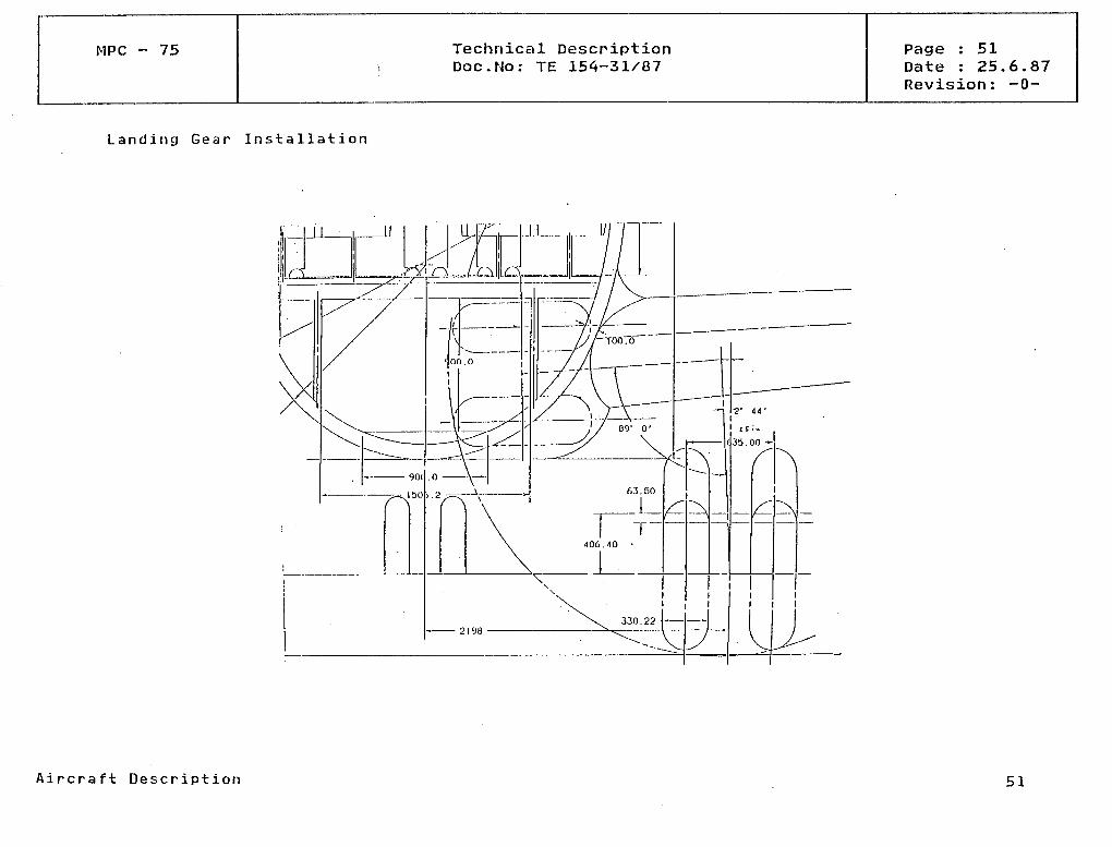
MPC - 75 Technical DescriptionDoc.No: TE 154-31/87
Page : 51Date : 25.6.87Revision: -0-
Landing Gear Installation
' MV
X iNv l
\ 330.22h —
li
J
J
l1
J^
Aircraft Description 51

MPC - 75 Technical DescriptionDoc.No: TE 154-31/87
Page : 52Date : 25.6.87Revision: -0-
Landing Gear Geometry
13869 -
4276
635
Aircraft Description 52

MPC - 75 Technical DescriptionDoc.No: TE 154-31/87
Page :.53Date :Revision: -0-
ACN
20-
15-
10-
RIGID PAVEMENT
SUBGRADE STRENGTH
K = 20 MN/M3(ULTRA LOW)
K = 40 MN/M3(LOW)
K = 80 MN/M3(MEDIUM)
K = 150 MN/M'(HIGH)
GEAR TYPE
TIRE SIZE
TIRE PRESSURE
TIRE SPACING
PERCENT WEICHT ON MLG
DUAL WHEEL
39"x13"
105 PSI
21"
95.0
26000 28000 30000 AIRCRAFT WEICHT ( K G )
l A i r c r a f t Descr ip t ion 53
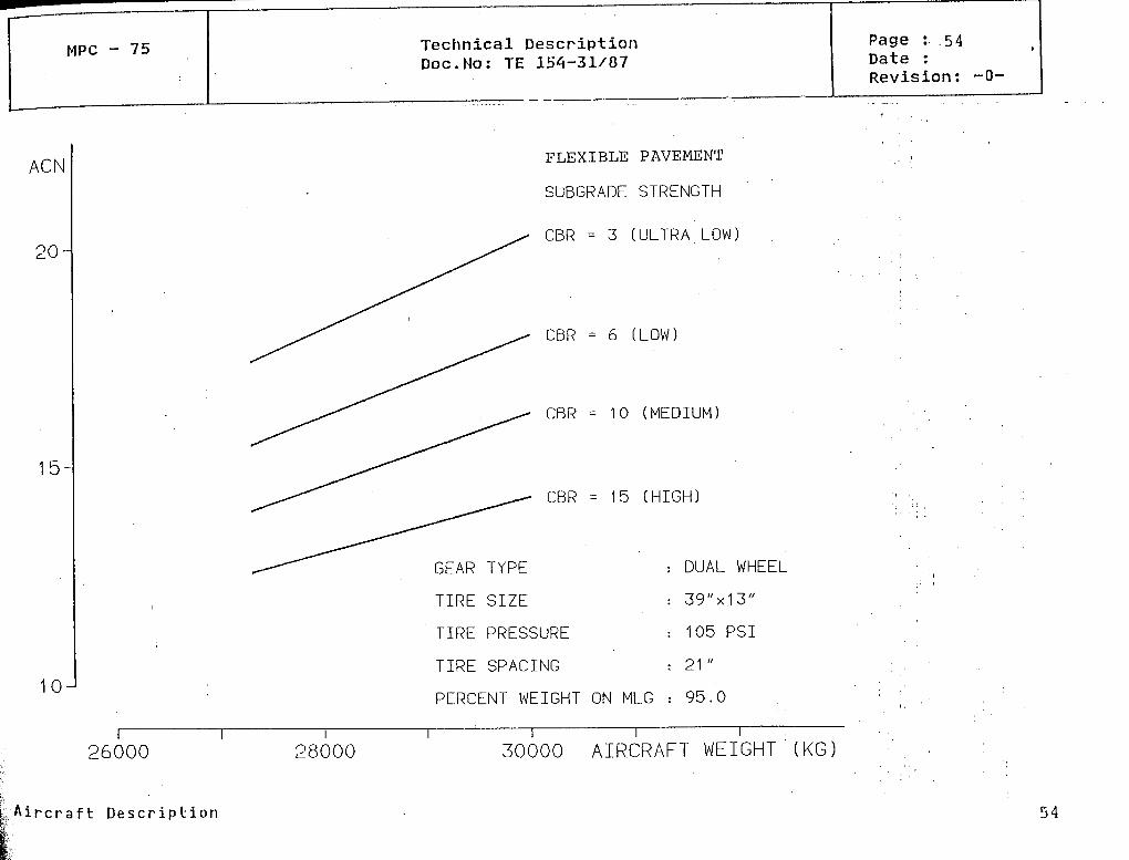
MPC - 75
ACN
20-
15-
10J
26000
Technical DescriptionDoc.No: TE 154-31/87
Page :. .54Date :Revision: -O-
FLEXIBLE PAVEMENT
SUBGRADE STRENGTH
CBR = 3 (ULTRA LOW]
CBR = 6 (LOW)
CBR = 10 (MEDIUM)
CBR = 15 (HIGH)
GEAR TYPE
TIRE SIZE
TIRE PRESSURE
TIRE SPACING
DUAL WHEEL
39"x13"
105 PSI
21 "
PERCENT WEICHT ON MLG : 95.0
28000 30000 AIRCRAFT WEICHT (KG)
. A i r c r a f t D e s c r i p t i on 54
MPC 75 Technical DescpiptionDoc.No: TE 154-31/87
Page : 55Date : 25.6.87Revision: -0-
4.10 GROUND HANDLING
The aircraft is easily accessible to ground Service vehicles (see Diagram).
Turn-around times of less than 30 minutes are possible. Times for individual phases areshown in diagram. Critical time is the unloading and loading of the bulk cargo compart-m e n t s .
Aircraft Description 55
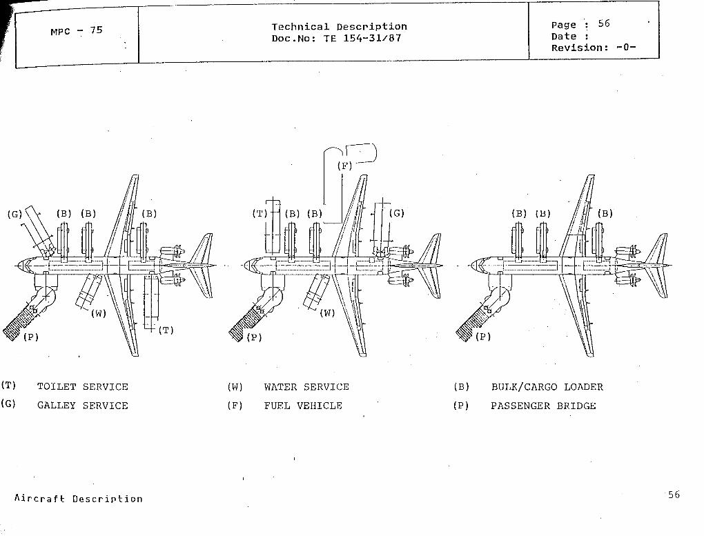
MPC - 75 Technical DescriptionDoc.No: TE 154-31/87
Page : 56Date :Revision: -0-
(G)\) TOILET SERVICE
(G) GALLEY SERVICE
(W) WATER SERVICE
(F) FUEL VEHICLE
(B) BULK/CARGO LOADER
(P) PASSENGER BRIDGE
A i r c r a f t D e s c r i p t i o n 56
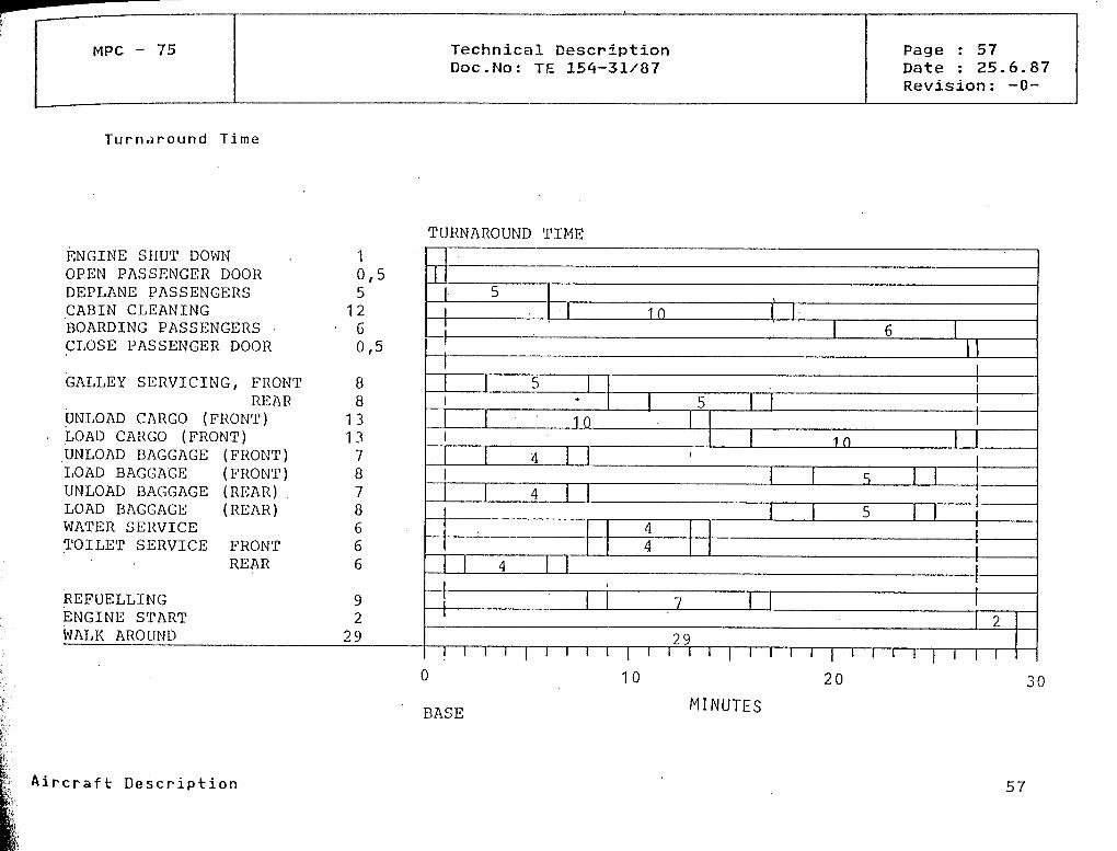
MPC - 75
Turnjround Time
Technical DescriptionDoc.No: TE 154-31/87
Page : 57Date : 25.6.87Revision: -0-
TURNAROUND TIME
ENGINE SHUT DOWN . 1OPEN PASSENGER DOOR 0,5DEPLANE PASSENGERS 5CABIN CLEANING 12BOARDING PASSENGERS : 6CLOSE PASSENGER DOOR 0,5
GALLEY SERVICING, FRONT 8REAR 8
UNLOAD CARGO (FRONT) 13LOAD CARGO (FRONT) 13UNLOAD BAGGAGE (FRONT) 7LOAD BAGGAGE (FRONT) 8UNLOAD BAGGAGE (REAR) 7LOAD BAGGAGE (REAR) 8WATER SERVICE 6TOILET SERVICE FRONT 6
REAR 6
REFUELLIMG 9ENGINE START 2WALK AROUND 29
(
l
)
510 l
. l 6I I
55 l
10l 10
4 *l S l
4l 5
44
l 4 l
7 l2
29i i [ | i | i l l | l l l ||
10 20 3
BASE MINUTES
A i r c r a f t Description 57

MPC 75 Technical DescriptionDoc.No: TE 154-31/87
Page : 58Date : 25.6.87Revision: -0-
5.0 SYSTEMS (IN ATA CHAPTER ORDER)
5.1 AIR CONDITIONING SYSTEM (ATA21)
GENERAL/
Air conditioning shall be provided by two vapour cycle packs using air from main engineshaft driven compressors. Pressurization will be achieved by controlling the outflow ofcabin air.
PERFORMANCE
Minimum fresh airflow requirements
Total 0,554 kg/s at S. L. and 0,411 kg/s at 8.000 ft cabinLoss of one air source: 0,37 kg/s at S. L. and
0,275 kg/s at 8.000 ft cabin.
CABIN TEMPERATURE
In flight with two packs, flight deck and cabin temperature shall be selectable in theränge 18° C - 30° C.
On ground with two packs, flight deck and cabin temperature of 21° C (cold day) or 27° C(hot day) shall be achieved within 30 minutes of system start.
Ground and flight Operation with one pack shall ensure acceptable temperature in flightdeck and cabin.
Systems (in ATA Cha p t e r order) 58
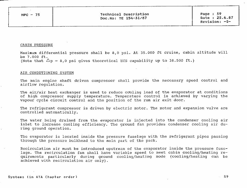
MPC - 75 Technical DescriptionDoc.No: TE 154-31/87
Page : 59Date : 25.6.87Revision: -0-
CABIN PRESSURE
Maximum differential pressure shall be 8,0 psi. At 35.000 ft cruise, cabin altitude willbe 7.000 ft.(Note that Ap =8,0 psi gives theoretical ECS capability up to 38.500 ft.)
AIR CONDITIONING SYSTEM
The main engine shaft driven compressor shall provide the necessary speed control andairflpw regulation.
The air/air heat exchanger is used to reduce co-oling load of the evaporator at conditionsof high compressor supply temperature. Temperature control is achieved by varying thevapour cycle circuit control and the position of the ram air exit door.
The refrigerant compressor is driven by electric motor. The motor and expansion valve arecontrolled automatically.
The v/ater being drained from the evaporator is injected into the condenser cooling airinlet to increase cooling efficiency. The ground fan provides condenser cooling air du-ring ground Operation.
The evaporator is located inside the pressure fuselage with the refrigerant pipes passingthrough the pressure bulkhead to the main part of the pack.
Recirculation air must be introduced upstream of the evaporator inside the pressure fuse-lage. The recirculation fan shall have variable speed to meet cabin cooling/heating re-quirements particularly during ground cooling/heating mode (cooling/heating can beachieved with recirculation air only).
Systems (in ATA Chapter order) 59
MPC - 75 Technical DescriptionDoc.No: TE 154-31/87
Page : 60Date : 25.6.87Revision: -0-
The electric heater is installed in the duct downstream of each pack primarily for use incold day ground Operation. The smaller heater in the flight deck supply duct provides ahigher flight deck supply temperature when required.
The overall system will be controlled by an airborne Computer.
PRESSURIZATION SYSTEM
The cabin shall be pressurised up to a nominal pressure of 8,0 psi by restricting theoutflow of the cabin air via an outflow valve. The outflow valve shall be designed toprovide thrust recovery.
The system shall automatically control the cabin pressure rate of change and cabin alti-tude.
Two identical, independent, pneumatically operated safety valves shall be installed toprovide positive and negative cabin pressure relief.
Loss of one air source shall not significantly affect cabin pressure control.
Systems (in ATA Cha p t e r order)

MPC - 75 Technical DescriptionDoc.No: TE 154-31/87
Page : 61Date : 25.6.87Revision: -0-
Environmental Control System Schematic Diagram
FILTER RECIRC CABINRECIRCULAT10N
FROM CABIN m9vnfü
i
— —1
.JEU.
TO CABIN
n
Systems (in ATA Chapter order) 61

MPC - 75 Technical DescriptionDoc.No: TE 154-31/87
Page : 62Date : 25.6.87Revision: -0-
5.2 AUTOMATIC FLIGHT CONTROL SYSTEM - AFCS (ATA 22)
PREMISE
A fall operational fly by wire flight control System with mechanical manual backup willbe available to fulfill manoeuver demand control functions (pilot input and stabilisationfor all axes), flight envelope protection, turn coordination and auto trim functions. Inaddition füll authority digital engine control (FADEC) will be used with engine protec-tion functions.
AUTO FLIGHT SYSTEM (AFS)
In the basic configuration a fail passive autoflight/flight director System with categoryII approach capability will be installed (AFS 1) to transmit commands to the fly by wireSystem and the FADECs.
The basic modes of the system will be
oooo
longitudinal: vertical speed hold, altitude hold, level change,lateral: heading hold/heading select, VOR/LOG mode,approach mode (ILS beam) to minimum use height,speed/mach mode.
There are provisions for
oo
land, go around mode, take off,ILS roll guidance.
There are provisions for a 2nd autoflight System for improved system integrity needed forCAT III landing capability. The above mentioned provisional modes can be activated withthe 2nd AFS installed only.
Systems (in ATA C h a p t e r order) 62

TMPC - 75 Technical Description
Doc.No: TE 154-31/87
Page : 63Date : 25.6.87Revision: -0-
FLIGHT MANAGEMENT SYSTEM
Optional Flight Management Capability (FMS 1) will be available in two levels of perfor-mance by add on hardware
level 1: lateral, vertical and speed (4D-)guidance based on flight plan conditions andnavigation sensor Information,
level 2: flight path/flight plan optimization based on airframe and engine models air-line cost index and actual flight conditions (ATC, weather);
For increased dispatchability there are provisions for a 2nd flight management system(FMS 2) .
CREW INDICATION AND CONTROL
Informations for indications (selected targets, modes, system Status) will be transmittedto DMCs, system failures and disconnects are transmitted to CMMS; pilot inputs are provi-ded for
AFS on a dedicated flight control unit (FCU, glare shield Controller),FMS on a multipurpose control and display unit (CDU, central pedestal).
Systems (in ATA Chapter order) 63
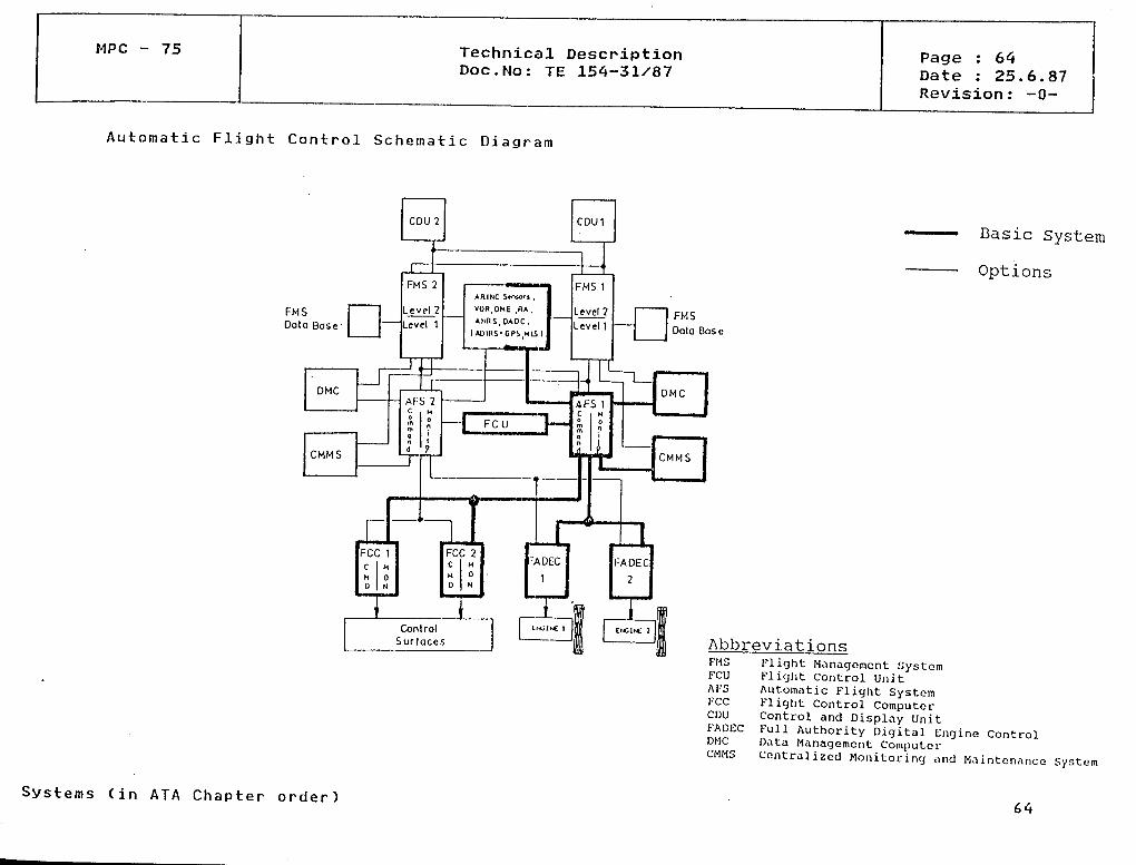
MPC - 75 Technical DescriptionDoc.No: TE 154-31/87
Page : 64Date : 25.6.87Revision: -0-
Automatic Flight Control Schematic Diagram
FMSOola Base
FMSData Base
Basic System
Options
AbbreviationsFlight Management SystemFlight Control Uni tAutomatic Flight SystemFlight Control ComputerControl and Display UnitFüll Authority Digital Engine ControlData Management ComputerCentralized Monitoring and Mnintonance System
Systems (in ATA Chapter order) 64

MPC - 75 Technical DescriptionDoc.No: TE 154-31/87
Page : 65Date : 25.6.87Revision: -0-
5.3 COMMUNICATIONS (ATA23)
The aircraft will be equipped with the following communication Systems:
o two VHF-radio Systems,o two HF-radio Systems (structural provisions) ,o two RMP (Radio Management Panel),o an audio Integration System (incorporating flight interphone amplifier and SELCAL
decoding) and ground crew call system,o a cockpit voice recorder (CVR),o a cabin intercommunication data system (CIDS), incorporating passenger address (PA)
system, cabin and flight crew interphone and service interphone system ando portable megaphone.
Adequate space is provided to allow for Systems growth and development during the opera-tional life of the aircraft.
Static dischargers are installed on the wing and tail unit trailing edges to minimizecorona discharge interference.
All of the communication Systems except CIDS use Solutions according to the state of theart.
An advanced technology system design is used for CIDS based on a microprocessor control-led data bus to provide improved passenger comfort, reduced crew workload and increasedflexibility to customer desires.
Systems (in ATA Chapter order)
MPC - 75 Technical DescriptionDoc.No: TE 154-31/87
Page : 66Date : 25.6.87Revision: -0-
5.4 ELECTRICAL POWER (ATA 24)
The main electrical power generation consists of a variable speed constant frequency(VSCF) system with two engine driven gerierators and their associated multiple-outputConverters. According to the electrical load estimate each generator has a capacity ofmax. 75 KVA. The generators deliver 115/200 V wild frequency AC power to the electricaldistribution system, where one part of it is used to feed the heating equipment whilstthe other part shall be converted to 115/200 V 400 Hz AC and to 28 V DC power.
The auxiliary generator driven by the APU is mainly used for ground service purposes.This generator with 115/200 V 400 Hz AC power Output and a power of 90 KVA can alsosubstitute an engine driven generator if the engine or the associated generator hasfailed. In case that the APU generator is feeding the electrical systera with AC power,the associated DC busses will be fed via a transformer rectifier unit (TRU).
Two batteries and one single phase static inverter provide emergency power. The batteriescan also start the APU. A 115/200 V 400 Hz AC ground power source can be used for groundservice purposes via the EXT PWR connector.
An advanced power distribution management system will be implied to achieve
ooo
failure management, remote circuit breaker and bus tie contactor control,load monitoring and priority administration,system Status data processing for indication and maintenance purposes
thus minimising generator power and wiring complexity and weight.
Systems (in ATA Chapter order) 66
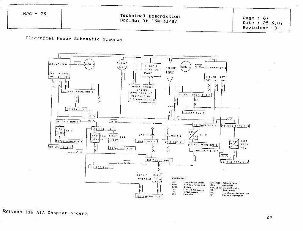
MPC - 75 Technical DescriptionDoc.No: TE 154-31/87
Page : 67Date : 25.6.87Revision: -0-
Electrical Power Schematic Diagram
M AN A(; t MC N l
S Y S I L' M
( C O N I n O t S IIIE
H E l E VAN I IIUS
11 E C O N I A r. l OII S )
AC Allcfonllng Curf cnl EXf PWfl Exlcfnnl PowerAI'U Auxillory l'üwcf UnU GfiN GcnefnlofU A l T Unllcfy CNUS6MV Giound ScivlccCT- C'oiul-inl f (cqucncy T H Tfonsluf/ncrOC OUccl Cuiicnl 1I1U Trnnslofmer flcclldcr UntlCSS l iJ lcnl lol VF Voilülilc f tenucncy
Systems (in ATA Chapter order) 67

MPC - 75 Technical DescriptionDoc.No: TE 154-31/87
Page : 68Date : 25.6.87Revision: -0-
5.5 FIRE PROTECTION (ATA 26)
Aircraft fire protection Systems with appropriate redundancy are provided for:
engines and APU, comprising fire detection and extinguishing system,
electronic bay with a smoke detection system,
lower deck holds comprising an optional smoke detection system and if desired anoptional fire extinguishing system,
o an automatic waste bin fire extinguishing system and smoke detectors in lavatorles.
Additionally portable fire extinguishers are installed in the flight compartment and thepassenger cabin.
Svstems (in ATA C h a p t e r order 68
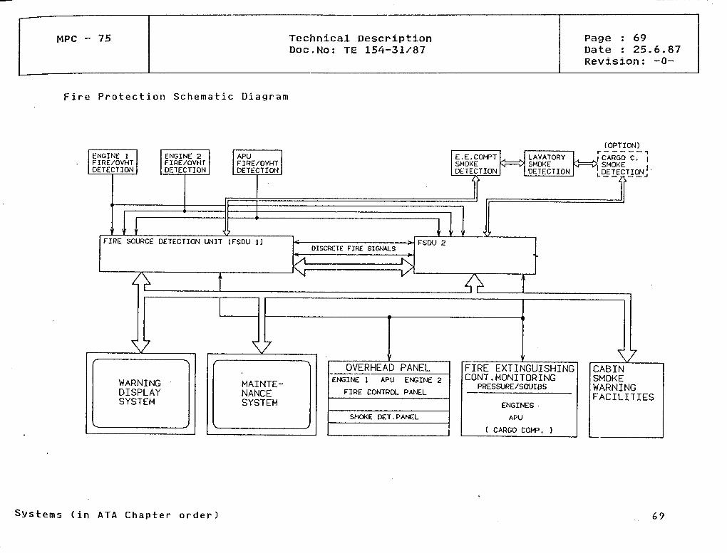
MPC - 75 Technical DescriptionDoc.No: TE 154-31/87
Page : 69Date : 25.6.87Revision: -0-
Fire Protection Schetnatic Diagram
FIRE SOURCE DETECTION UN1T (FSDU 1)
V
WARNINGDISPLAYSYSTEM
DISCRETE FIRE SIGNALS« >
V
MAINTE-NANCESYSTEM
OVERHEAD PANELENGINE l APU ENGINE 2
FIRE CONTROL PANEL
SMOKE DET.PANEL
FIRE EXTINGUISHINGCONT.MONITORING
PRESSURE/SOUIBS
ENGINES
APU
( CARGO COP. )
rODPT10N)_
j CARGO C. l' SMOKE |UDETECTIONJ
VCABINSMOKEWARNINGFACILITIES
Systems Cin ATA Chapter o r d e r )
MPC - 75 Technical DescriptionDoc.No: TE 154-31/87
Page : 70Date : 25.6.87Revision: -0-
5.6 FLIGHT CONTROLS (ATA 27)
Primary and secondary flight control electrical signalling is integrated into the flightcontrol Computers (FCC), which include command shaping, flight augmentation, speed depen-ding Output limitation and sensor and Computer failure monitoring functions.
Each primary control axis (roll, yaw and pitch) is supplied by two independent hydraulicSystems and at least two independent electric power Systems.
Each primary control axis is operated by duplicated electrohydraulic servo actuators withfailure monitoring of each channel or alternatively (back up) by a single mechanical linkfrom the pilot's control stations.
The electrohydraulic servo actuators are signalled from sensors located at the pilot'scontrol stations or from tjie auto-flight system via duplicated flight control Computers(FCC's) with failure monitoring of each channel.
The trimmable horizontal stabilizer is operated by a fail-safe designed electro-mecha-nical actuator which is driven by two independent electromotors via a differential gearbox. The two motors are independently controlled by the pilot's control switches or bythe autotrim-modes of the autoflight-system.
The flaps are operated by a mechanical transmission system driven by a centralized dualmotor power drive unit and controlled by the pilot's control lever via the flight controlComputers (FCC's). The monitoring is provided by the FCC's.
The spoilers provide roll, airbrake and lift dump functions. Each spoiler is actuated byan electrohydraulic actuator and controlled by the pilot's roll controls, airbrake leverand/or auto-flight/land system via the two flight control Computers (FCC's).
Systems (in ATA Chapter o r d e r ) 70
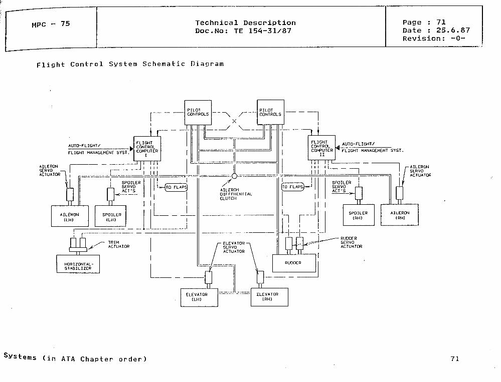
MPC - 75 Technical DescriptionDoc.No: TE 154-31/87
Page : 71Date : 25.6.87Revision: -0-
Flight Control System Schematic Diagram
AILERON lSERVO —.ACTUATOR '
AUTD-FLIGHT/
FLICHT MANAGEMENT SYST.
-AILERONSERVO
SPOILER !SERVO r-L-iACT'S | 1
WSPOILER(RH)
; AL.I
dAILERON(RH)
RUDOERSERVOACTUATOR
Systems (in ATA Chapter order) 71
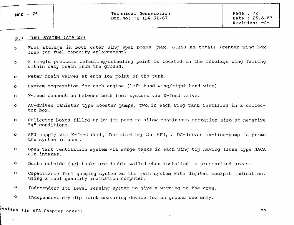
MPC - 75 Technical DescriptionDoc.No: TE 154-31/87
Page : 72Date : 25.6.87Revision: -0-
5.7 FUEL SYSTEM (ATA 28)
o Fuel storage in both outer wing spar boxes (max. 6.150 kg total) (center wing boxfree for fuel capacity enlargement).
o A single pressure refueling/defueling point is located in the fuselage wing fairingwithin easy reach from the ground.
o
o
o
o
o
o
o
o
Water drain valves at each low point of the tank.
System segregation for each engine (left hand wing/right hand wing).
X-feed connection between both fuel Systems via X-feed valve.
AC-driven canister type booster pumps, two, in each wing tank installed in a collec-tor box.
Collector boxes filled up by jet pump to allow continuous Operation also at negative"g" conditions.
APU supply via X-feed duct, for starting the APU, a DC-driven in-line-pump to primethe System is used.
Open tank Ventilation System via surge tanks in each wing tip having flush type NACAair intakes.
Ducts outside fuel tanks are double walled when installed in pressurized areas.
Capacitance fuel gauging system äs the main system with digital cockpit indication,using a fuel quantity indication Computer.
Independent low level sensing system to give a warning to the crew.
Independent dry dip stick measuring device for on ground use only.
»Vstems (in ATA chapter order 72
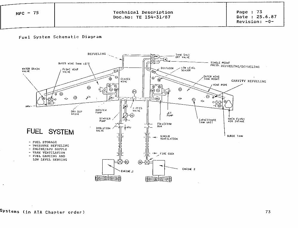
MPC - 75 Technical DescriptionDoc.No: TE 154-31/87
Page : 73Date : 25.6.87Revision: -0-
Fuel System Schematic Diagram
REFUELING ______ TANK SHUT" OFF VAUVE
Outen wlNG TANK LEF
WATER Of<AlNVAtVE
GRAVITY REFUELING
FUEL SYSTEM- FUEL STORAGE- l'RESSURE REFUELING- ENGINE/Al 'U SUPI'LY- M'ANK VENTILATION- FUEL GAUGING AND
LOW LEVEL SENSING
ENGINE 2
NACA FLUSHAIR INTAKE
SURGE TANK
Svstems (in ATA Chapter order) 73
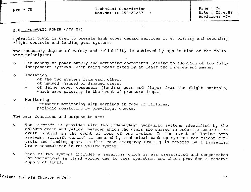
MPC - 75 Technical DescriptionDoc.No: TE 154-31/87 '*•
Page : 74Date : 25.6.87Revision: -0-
5.8 HYDRAÜLIC POWER (ATA 29)
Hydraulic power is used to operate high power demand Services i. e. primary and secondaryflight controls and landing gear Systems.
The necessary degree of safety and reliability is achieved by application of the follo-wing principles:
o Redundancy of power supply and actuating components leading to adoption of two fullyindependent Systems, each being pressurized by at least two independent means.
o Isolationof the two Systems from each other,of unused, jammed or damaged users,of large power consumers (landing gear and flaps) from the flight controls,which have priority in the event of pressure drops.
o MonitoringPermanent monitoring with warnings in case of failures,periodic monitoring by pre-flight checks.
The main functions and components are:
o The aircraft is provided with two independent hydraulic Systems identified by thecolours green and yellow, between which the users are shared in order to ensure air-craft control in the event of loss of one system. In the event of losing bothSystems, aircraft control is ensured by mechanical back up Systems for flight con-trols and landing gear. In this case emergency braking is powered by a hydraulicbrake accumulator in the yellow system.
o Each of two Systems includes a reservoir which is air pressurized and compensatesfor variations in fluid volume due to user Operation and which provides a reservesupply of fluid.
Systems (in ATA Chapter o r d e r ) 74
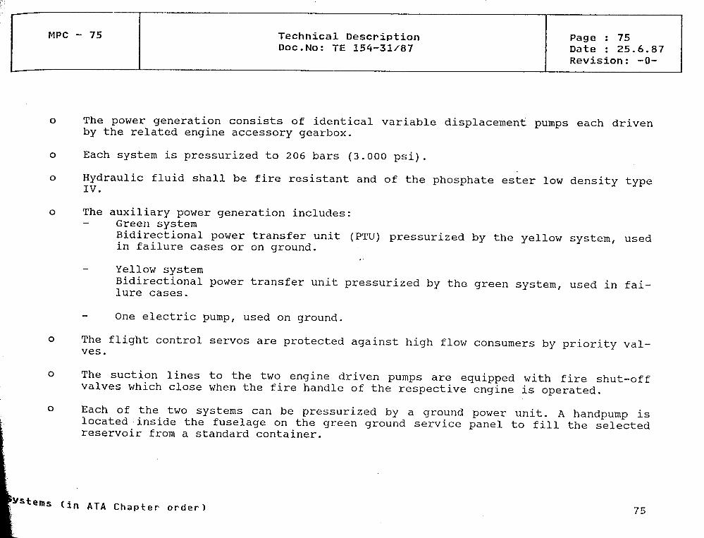
MPC - 75 Technical DescriptionDoc.No: TE 154-31/87
Page : 75Date : 25.6.87Revision: -0-
o The power generation consists of identical variable displacement pumps each drivenby the related engine accessory gearbox.
o Each system is pressurized to 206 bars (3.000 psi).
o Hydraulic fluid shall be fire resistant and of the phosphate ester low density typeIV.
o The auxiliary power generation includes:- Green system
Bidirectional power transfer unit (PTU) pressurized by the yellow system, usedin failure cases or on ground.
Yellow systemBidirectional power transfer unit pressurized by the green system, used in fai-lure cases.
One electric pump, used on ground.
o The flight control servos are protected against high flow consumers by priority val-ves.
o The suction lines to the two engine driven pumps are equipped with fire shut-offvalves which close when the fire handle of the respective engine is operated.
o Each of the two Systems can be pressurized by a ground power unit. A handpump islocated inside the fuselage on the green ground Service panel to fill the selectedreservoir from a Standard Container.
< i n ATA Chapter order) 75
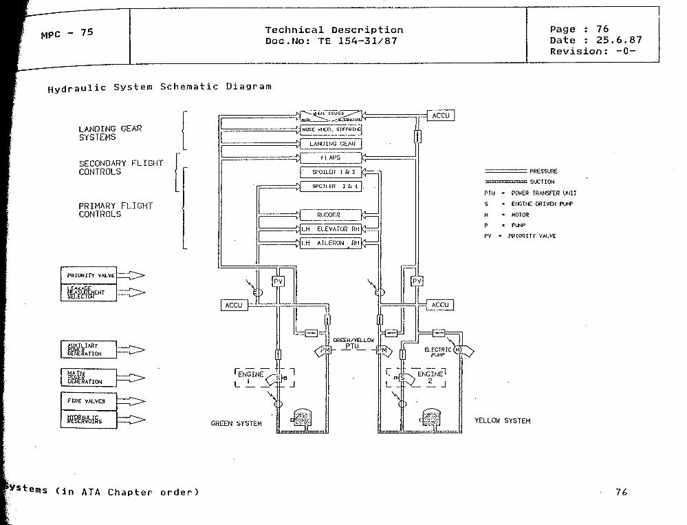
MPC ' 75 Technical DescriptionDoc.No: TE 154-31/87
Page : 76Date : 25.6.87Revision: -0-
H y d r a u l i c System S c h e m a t i c D i a g r a m
LANDING GEARSYSTEMS
SECONDARY FLICHTCONTROLS
PRIMARY FLICHTCONTROLS
l
/J
/*
t1t
__ _ v
^v
1 ENGINE
L i. _\N SYSTEM
= PRESSURE
nrm SLCriON
PTU • POWER TRANSFER UNIT
S - ENGINE ORIVEN PUhP
H • MOTOR
P • PLMP
PV - PRWRITY VALVE
YELLOW SYSTEM
B
^Sterns (in ATA Chapter order) 76
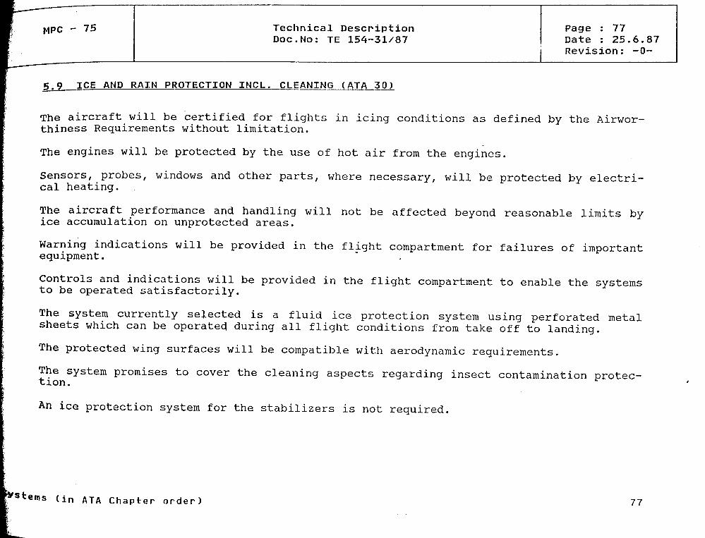
- 75 Technical DescriptionDoc.No: TE 154-31/87
Page : 77Date : 25.6.87Revision: -0-
AND RAIN PROTECTION INCL. CLEANING (ATA 30)
The aircraft will be certified for flights in icing conditions äs defined by the Airwor-thiness Requirements without limitation.
The engines will be protected by the use of hot air from the engines.
Sensors, probes, Windows and other parts, where necessary, will be protected by electri-cal heating.
The aircraft performance and handling will not be affected beyond reasonable limits byice accuraulation on unprotected areas.
Warning indications will be provided in the flight compartment for failures of importantequipment.
Controls and indications will be provided in the flight compartment to enable the Systemsto be operated satisfactorily.
The System currently selected is a fluid ice protection system using perforated metalsheets which can be operated during all flight conditions frora take off to landing.
The protected wing surfaces will be compatible with aerodynamic requirements.
The system promises to cover the cleaning aspects regarding insect contamination protec-tion.
An ice protection system for the stabilizers is not required.
(in ATA Chapter order) 77
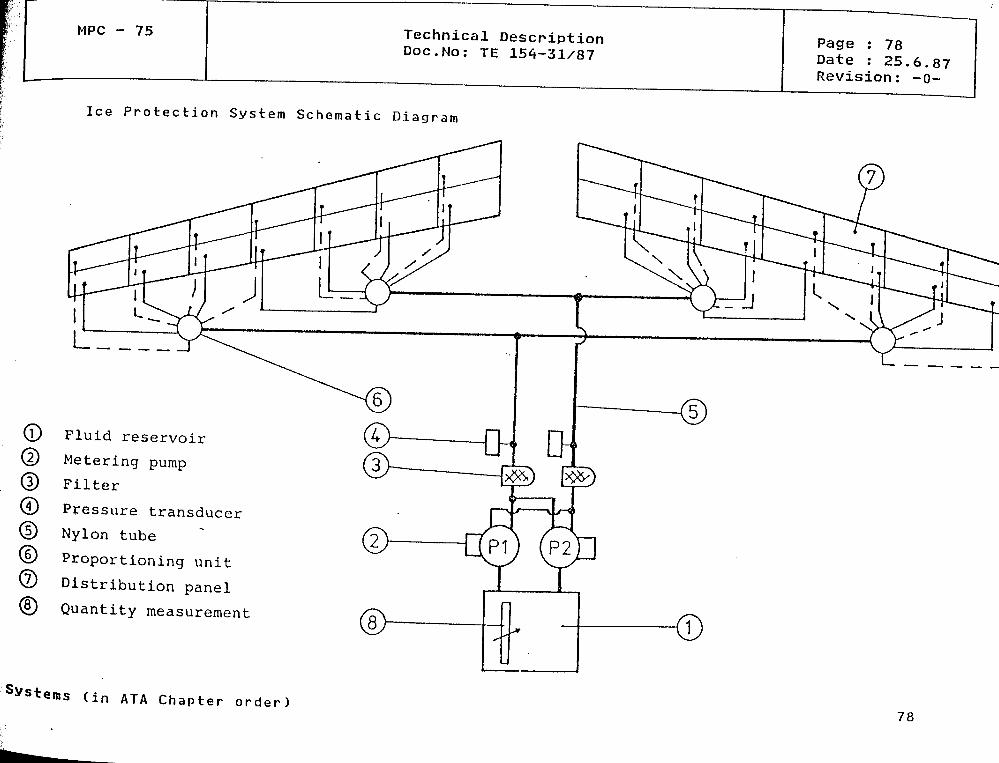
MPC - 75 Technical DescriptionNo: TE 154-31/87
Page : 78Date : 25.6.87Revision: -0-
Ice Protection System Schematic Diagram
(L
(
(5)
©
(S]
Fluid reservoir
Metering pump
Filter
Pressure transducer
Nylon tube
Proportioning unit
Distribution panel
Quantity measurement
Systems (in ATA Chapter order) 78

MPC - 75 Technical DescriptionDoc.No: TE 154-31/87
Page : 79Date : 25.6.87Revision: -0-
5.10 COCKPIT AND INSTRUMENTS (ATA 31)
The cockpit will be a two men cockpit with all control panels within easy reach of thetwo crew members and a third seat for a flight observer.
The general arrangement of the Instruments and controls is given in the main panel, cen-tral pedestal and overhead panel schematics.
An electronic Instrument system (EIS) consisting 'Of 6 interchangeable display units forprimary flight displays (PFD) and navigation displays (ND) at each side and centralengines and Systems displays (CMMS) is provided. The EIS will have reconfigurationcapability to select function priorities in case of display or symbol generator failures.Fiat panel displays will be used äs soon äs available.
A minimum stand-by Instrumentation will allow safe flight hörne in case of loss of EIS dueto füll loss of electrical power.
A centralized maintenance and monitoring system is provided using engines and Systemsdisplays and incorporating all centralized warnings.
Push button technology will be applied - wherever possible - instead of switches; func-tion and warning lights will only appear depending on pilots need to know or if it isrequired.
The intercommunication Standard between avionic equipment will be ARINC 429. Depending onhardware availability, system maturity and data rate necessities ARINC 629-standards willbe applied, if useful in mixed versions with ARINC 429.
The new racking concept replacing ARINC NIC600 will be applied depending on Systems avai-lability and maturity and customer requirements.
Fibre optics will be used for crosscommunication between lanes in redundant ComputerSystems to reduce EMI and lightning strike interferences, to achieve decoupling of vol-tage potential.
(in ATA Chapter order) 79

MPC - 75 Technical DescriptionDoc.No: TE 154-31/87
Page : 80Date : 25.6.87Revision: -0-
Cockpit - Main Panel/Glare Shield
Master warning L t
Master caution Lt
- Stby ASIStby ALT
EFIS CTL
LDG GEAR IND
BRK./A-SKID CTL
Stby ATT
LDGGEARCTL LVR
(in ATA Chapter order) 80
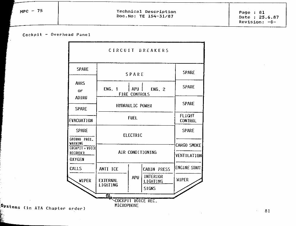
MPC - 75 Technical DescriptionDoc.No: TE 154-31/87
Page : 81Date : 25.6.87Revision: -0-
Cockpit - Ove rhead Panel
C I RCU ]
SPARE
AHRS
or
ADIRU
SPARE
EVACUATION
SPARE
GROUNO PROX.WARN1NGCOCKPI I+VOKERECORDER
OXYGEN
CALLS
iXWIPER
S
ENG. 1FIRE
T B R E A K E R S
P A R E
APUCONTR
ENG. 2ÖLS
HYDRAUL IC POWER
FUEL
ELECTRIC
AIR CONDITIONING
ANTI ICE
EXTERNALLIGHT1NG
APU
CABIN PRESS
INTERIORLIGHTING
SIGNS
SPARE
SPARE
SPARE
FLIGHTCONTROL
SPARE
CARGO SMOKE
VENTILATION
ENGINE START
HIPER ^S
( in ATA Chapter o rder )
COCKPIT VOICE REC.MICROPHONE
81

MPC - 75 Technical Descriptionpoc.No: TE 154-31/87
Page : 82Date : 25.6.87Revision: -0-
Cockpit - Pedestal
TIIRUSI &THRUSI REVERSECIL LEVERS
SPEED BRAKE
IIANDSEI
Multipur-poseCDU(option)
RadioManagementPanel
AUDIOCIL
LightingPanel
RADAR
— • ___
C M M S C I L
SWIICIIING
•:
u
a-
SPARE
- _ E —
2 f
ENG.SIARI
nS
0U(jU
Multipur-poseCDU(option)
RadioManagementPanel
AUDIOCIL
EventDFDR
ATC
- — "
SPARE
F
P
P
LGE
A b b r c v i a t i o n s :
CMMS
MCDU
C T L
FLAP HANDLE
RUD IR1M
PITCII TRIM
PARKING BRAKE
LDG GEARGRAVIIYEXIENSION HANDLE
CENTRALIZEDMAINTENANCEANDMONITORINGSYSTEM
MULTIPURPOSECONTROL ANDDISPLAYUNII
CONTROLPANEL
(In ATA Chapter order) 82
MPC - 75 Technical DescriptionDoc.No; TE 154-31/87
Page : 83Date : 25.6.87Revision: -0-
5.11 LANDING GEAR (ATA 32)
The MPC-75 landing gear is of the conventional retractable tricycle type with direct-action shock absorbers. The main twin wheel landing gears are located under the wings andretract sideways towards the fuselage centreline. The nose landing gear retracts forwardinto the fuselage. The gears and gear doors are actuated hydraulically, the sequencingbeing electrically achieved with the use of proximity detectors and associated logic con-trols. The four wheels of the main landing gear are provided with a multi-disc carbonbrake system incorporating the normal anti-skid braking system. Radial and conventionaltyres in various sizes shall be available äs Standard options. Features for the attach-ment of towing and debogging means are provided besides jacking points. External lugs areinounted on the wheel axles for the Installation of sensors for an optional weight andbalance system. An electrically controlled, hydraulically powered nose gear steeringsystem shall be provided.
In case of emergency the gear uplock and door lock mechanisms can be manually released,followed by free fall extension and locking down of the gears with spring assistance.
'Sterns (in ATA Ch a p t e r order) 83

MPC - 75 Technical DescriptionDoc.No: JE 154-31/87
Page : 84Date : 25.6.87Revision: -0-
5.12 NAVIGATION (ATA 34)
The aircraft will be equipped with the following navigation Systems according to CAT IIrequirements:
1. AIR DATA SYSTEM
o Two DIGITAL AIR DATA COMPUTERS (DADC) with space provision for a third unit.o Three AIR DATA MODULES (ADM) linked to pitot probes.o Five ADM's linked to static ports.o One TOTAL AIR TEMPERATURE (TAT) probes.o Two ANGLE OF ATTACK (AOA) vanes.o One stand-by airspeed indicator connected to the stand-by-pitot source.o One stand-by altitude indicator connected to the stand-by-static source.
2. ATTITÜDE AND HEADING SYSTEM/INERTIAL REFERENCE
o Two ATTITUDE/HEADING REFERENCE SYSTEMS (AHRS) or optional,two inertial reference Systems (IRS) with space provision for a third unit.
o One stand-by-attitude reference given by a seif contained gyro-horizon.o One stand-by-magnetic corapass.o One ADIRS Control and display unit.
DADC and AHRS/IRS may be integrated into the ADIRU.
Space Provision in the ADIRU allow the Integration of Global Position System (GPS)to a combined System.
3. LANDING AID INFORMATION SYSTEM
o One Marker Beacon System (MKR) included in the VOR-receiver 1.o Two ILS-receivers (localizer and glide slope) or equivalent MLS (Microwave Lan-
ding System) if operational.
(in ATA C h a p t e r order) 84
MPC - 75 Technical DescriptionDoc.No: TE 154-31/87
Page : 85Date : 25.6.87Revision: -0-
INDEPENDENT POSITION INFORMATION SYSTEM
o One Weather Radar System (WXR).o One Radio Altimeter System (RALT), with space provision for a second RALT.o One Ground Proxiinity Warning System (GPWS) .
DEPENDENT POSITION INFORMATION SYSTEMi
o Two VOR receivers.o Two DME Interrogators.o One ATC transponder, with space provision for a second ATC and future Systems
such äs ATC Mode S.o One ADF system with space provision for a second ADF.
INSTRUMENT MONITORING
The navigation data presentation is displayed on the Electronic Instrument Systems(EIS), PFD (Primary Flight Display) and ND (Navigation Display) of each pilot.
NAVIGATION CONTROL
o Two Radio Management Panels (RMP) at the Captain's and First Officer's posi-tions.
If the optional Flight Management System (FMS) is installed äs part of theFlight Management and Guidance System (FMGS), the NAV-radios are controlled bythe FMGS.
»Vstems (in ATA Chapter order) 85
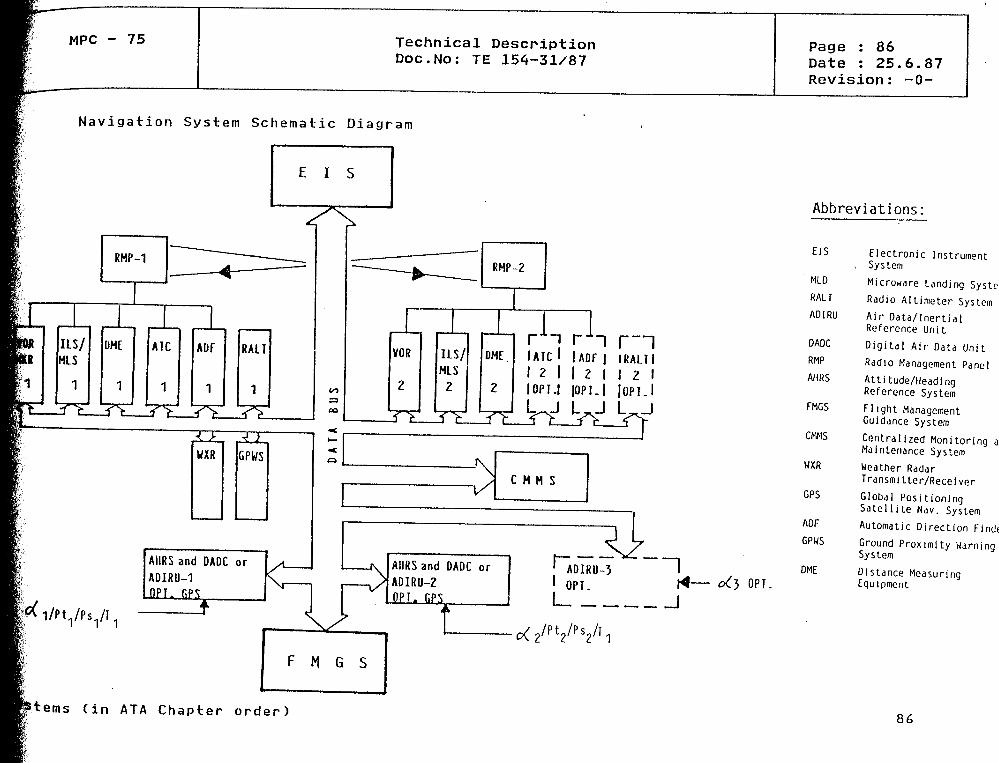
MPC - 75 Technical DescriptionDoc.No: TE 154-31/87
Page : 86Date : 25.6.87Revision: -0-
Navigation System Schematic Diagram
E I S
Abbreviations:
r1-! i r~l| A D F | I R A L T I
\ 2 \ \ 2 \ \ Z \I JOPI.I JOPI l
r J UJ
AIIRS and DADC orADIRU-1O F T . EPS
•VC M H SV ..
F M G S
AIIRS and DADC orADIRU-2DPI. GPS
t k
EIS
MLD
RALT
ADIRU
DADC
RMP
AHRS
FMGS
CMMS
UXR
GPS
ADF
GPWS
DMEO P T .
Electronic Instrument, System
Microwdre Landing SystemRadio Altimeter SystemAir Data/InertialReforence UriitDigital Air Data UnitRadio Management PanelAttitude/HeadingReference SystemFlight ManagementGuidance System
Centralized Monitoring andMaintenance SystemWeather RadarTransmitter/Recei verGlobal PositionlngSatellite Nav. SystemAutomatic Direction FinderGround Proximity WarningSystem
Distance MeasuringEquipment
i tems ( in ATA Chapter o r d e r )86
MPC - 75 Technical DescriptionDoc.No: TE 154-31/87
Page : 87Date : 25.6.87Revision: -0-
5.13 PNEUMATIC SYSTEM (ATA 36)
Pressurized air is needed foro Environmental Control System (ECS),o Main Engine Starting (MES),o Service Air to
Water System (ATA 38),Hydraulic System (ATA 29),Rain Repellent (ATA 30).
Pressurized air is generated by:o APU load compressor,o Engine shaft driven compressor at each main engine,o Ground air supply from an external air squrce.
All air supply sources are connected to a distribution system which allows the individualfunctions mentioned above.
The APU is controlled by its own Computer (ECB, electronic control box) including com-pressor control and valve shut-off function.
The ECS Packs and the Pneumatic System including engine driven compressors are controlledby two separate Computers (ECS/PNEUM. COMP. 1 + 2 ) having integrated functions for bothSystems äs primary and secondary control source. Interface between ECB and ECS/Pneum.Computer is provided to cater for integrity between both air supply Systems.
Sterns (in ATA C h a p t e r order) 87

MPC - 75 Technical DescriptionDoc.No: TE 154-31/87
Page : 88Date : 25.6.87Revision: -0-
Pneumatic System Schematic Diagram
VXoCD
5LUO
STARTER
GEN. 1
ENGINE 1
'Sterns (in ATA Chapter order) 88
MPC - 75 Technical DescriptionDoc.No: TE 154-31/87
Page : 89Date : 25.6.87Revision: -0-
5.14 AIRBORNE AUXILIARY POWER (ATA 49)
The AUXILIARY POWER UNIT (APU) for MPC-75 shall be capable of main engine starting andproviding air-condition power and electrical energy while on the ground. The APU shallalso be capable of providing electrical power in-flight, e. g. in the event of engine orgenerator failure. APU is located aft of the pressure bulkhead in the tail body. It willbe located and the installation designed so äs to permit easy maintenance and accessi-bility. The installation design will incorporate noise attenuation features so that noisewill not exceed 85 DBA at the nearest service or passenger entrance.
An APU Monitoring System (AMS) will be implied into the Centralized Maintenance and Moni-toring System (CMMS). The purpose of AMS is to monitor secondary power System health in-cluding the APU related aircraft bleed air system supply. AMS will acquire, analyse andstöre APU performance data and will alert the airline of any eminent system problems viaalert reports.
An Electronic Control Box (ECB) will be accommodated in the pressurized compartment ofthe aircraft, and all controls and indications necessary to operate monitor and assistraaintenance of the APU will be accommodated in the flight deck.
"ems (in ATA Chapter order) 89