mpls traffic engineering -...
TRANSCRIPT

1Traffic Engineering © 1999, Cisco Systems, Inc.
MPLSTraffic Engineering
MPLSTraffic Engineering
George Swallow
George Swallow

2Traffic Eng. © 1999, Cisco Systems, Inc. Cisco Systems
What is Traffic EngineeringWhat is Traffic Engineering
Taking control of how traffic flows in yournetwork in order to -
ÿImprove overall network performance
ÿOffer premium services
ÿAs a tactical tool to deal with network designissues when the longer range solution are notdeployed
3Traffic Eng. © 1999, Cisco Systems, Inc. Cisco Systems
Voice Traffic Engineering
• Telco’s noticed that demands varywidely by time of day
• Began “engineering the traffic”long ago
• Evolved over time
• Now fully automated
4Traffic Eng. © 1999, Cisco Systems, Inc. Cisco Systems
Reasons for Traffic Engineering
• Economics – more packets, fewer $$$
• Address deficiencies of IP routing
• Tactical tool for network operations
• Class-of-service routing

5Traffic Eng. © 1999, Cisco Systems, Inc. Cisco Systems
Mike O’Dell, UUnet
Economics of Traffic Engineering
““The efficacy with which one uses theThe efficacy with which one uses theavailable bandwidth in the transmissionavailable bandwidth in the transmissionfabric directly drives the fundamentalfabric directly drives the fundamental‘‘manufacturing efficiencymanufacturing efficiency’’ of the of thebusiness and its cost structure.business and its cost structure.””
Savings can be dramatic. Studies have shown that transmission costs can be reduced by 40%.

6Traffic Eng. © 1999, Cisco Systems, Inc. Cisco Systems
The “Fish” Problema deficiency in IP routing
The “Fish” Problema deficiency in IP routing
IP uses shortest path destination based routingIP uses shortest path destination based routing
Shortest path may not be the only pathShortest path may not be the only path
Alternate paths may be under-utilized while theAlternate paths may be under-utilized while theshortest path is over-utilizedshortest path is over-utilized
R8
R2
R6
R3
R4
R7
R5
R1

7Traffic Eng. © 1999, Cisco Systems, Inc. Cisco Systems
Deficiencies in IP RoutingDeficiencies in IP Routing
• Chronic local congestion
• Load balancing
Across long haul links
• Size of links
Difficult to get IP to make good use unequal sizelinks without overloading the lower speed link

9Traffic Eng. © 1999, Cisco Systems, Inc. Cisco Systems
Overlay Motivation
Separate Layer 2 Network (Frame Relay or ATM)
Mike O’DellUUnet, November 17, 1996
““The use of the explicit Layer 2 transit layerThe use of the explicit Layer 2 transit layergives us very exacting control of howgives us very exacting control of howtraffic uses the available bandwidth intraffic uses the available bandwidth inways not currently possible by tinkeringways not currently possible by tinkeringwith Layer 3-only metrics.with Layer 3-only metrics.””

10Traffic Eng. © 1999, Cisco Systems, Inc. Cisco Systems
The Overlay Solution
• Layer 2 network used to managethe bandwidth
• Layer 3 sees a complete mesh
L3L3
L3L3
L3L3
L3L3
L3L3
L3L3
L3L3
L2L2
L2L2
L2L2
L2L2
L2L2
L2L2
L3L3
L3L3
L3L3
L3L3 L3L3
Physical Logical

11Traffic Eng. © 1999, Cisco Systems, Inc. Cisco Systems
Overlay Drawbacks
• Extra network devices (cost)
• More complex network management
Two-level network without integrated NM
Additional training, technical support,field engineering
• IGP routing doesn’t scale for meshes
Number of LSPs generated for a failed router isO(n3); n = number of routers

12Traffic Eng. © 1999, Cisco Systems, Inc. Cisco Systems
Traffic Engineering & MPLS
• MPLS fuses Layer 2 and Layer 3
• Layer 2 capabilities of MPLS canbe exploited for IP traffic engineering
• Single box / network solution
+ oror=
Router ATM Switch MPLSRouter
ATM MPLS Router

13Traffic Eng. © 1999, Cisco Systems, Inc. Cisco Systems
An LSP TunnelAn LSP Tunnel
R8
R2
R6
R3
R4
R7
R5
R1
Normal Route R1->R2->R3->R4->R5
Tunnel: R1->R2->R6->R7->R4
Labels, like VCIs can be used to establish virtualcircuits
21Traffic Eng. © 1999, Cisco Systems, Inc. Cisco Systems
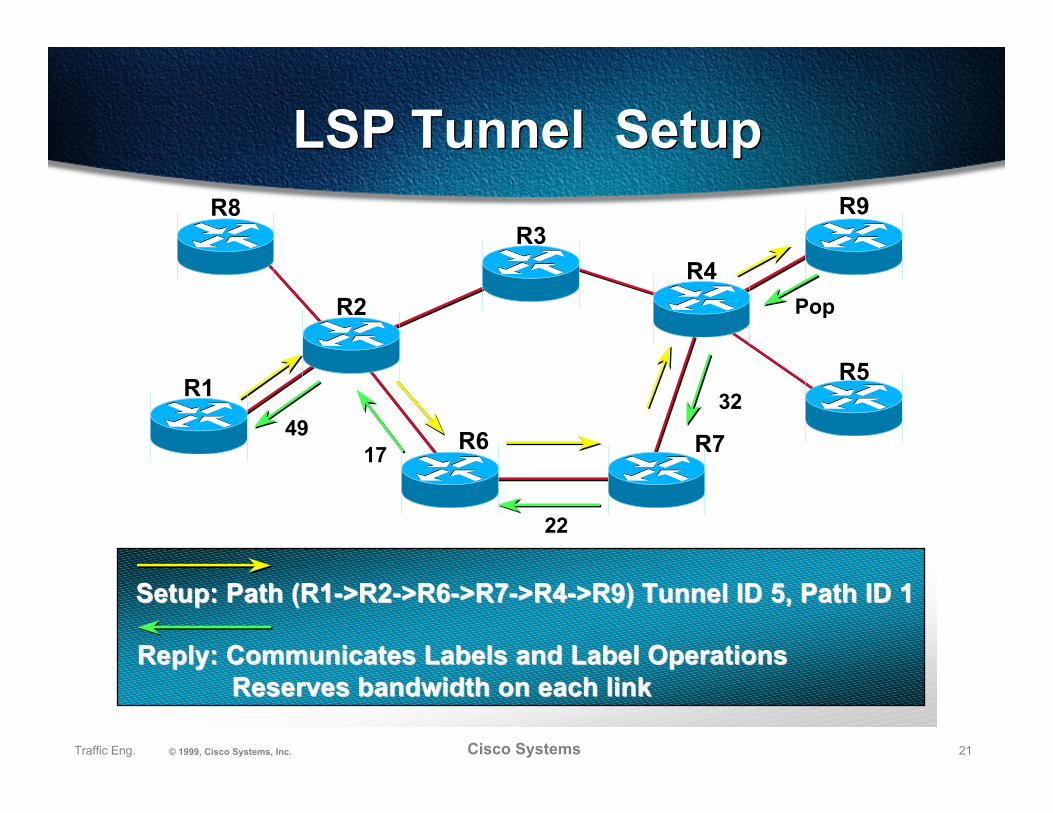
LSP Tunnel SetupLSP Tunnel Setup
Setup: Path (R1->R2->R6->R7->R4->R9) Tunnel ID 5, Path ID 1Setup: Path (R1->R2->R6->R7->R4->R9) Tunnel ID 5, Path ID 1
22
4917
R8
R2
R6
R3
R4
R7
R1R5
R9
Reply: Communicates Labels and Label OperationsReply: Communicates Labels and Label OperationsReserves bandwidth on each linkReserves bandwidth on each link
Pop
32

22Traffic Eng. © 1999, Cisco Systems, Inc. Cisco Systems
Multiple Parallel Tunnels
• Automatically load shared
• Weighted by bandwidth
to nearest part in 16
• Traffic assigned by either
Source-Destination hash
Round robin

23Traffic Eng. © 1999, Cisco Systems, Inc. Cisco Systems
Automatic Load BalancingAutomatic Load Balancing
New York#1
New York#2
Washington
London#1
London#2
Paris
Stockholm
Munich
Brussels
Frankfurt
Amsterdam
Link #1
Link #2
Link #3
LSP Tunnel #1
LSP Tunnel #2
LSP Tunnel #3

24Traffic Eng. © 1999, Cisco Systems, Inc. Cisco Systems
Additional FeaturesAdditional Features
• Adjusting to failures
Requires rapid notification
• Adjusting to improvements
• Need to account for
Global optimality
Network stability
25Traffic Eng. © 1999, Cisco Systems, Inc. Cisco Systems
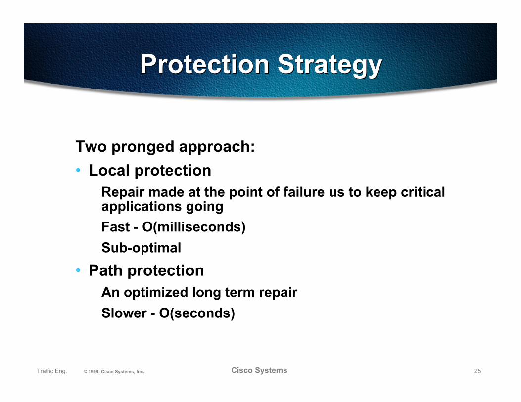
Protection StrategyProtection Strategy
Two pronged approach:
• Local protectionRepair made at the point of failure us to keep criticalapplications going
Fast - O(milliseconds)
Sub-optimal
• Path protectionAn optimized long term repair
Slower - O(seconds)
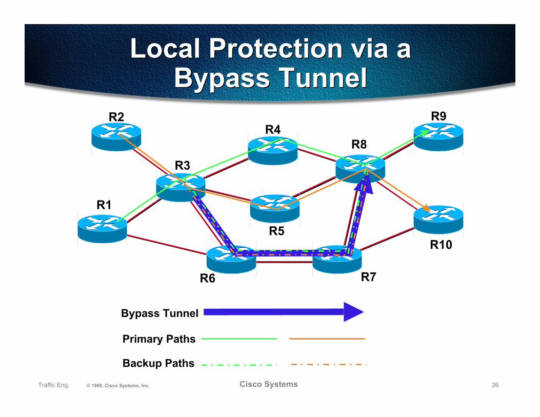
26Traffic Eng. © 1999, Cisco Systems, Inc. Cisco Systems
Local Protection via aBypass Tunnel
Local Protection via aBypass Tunnel
R2
R3
R6
R4R8
R7
R1
R10
R9
R5
Primary Paths
Bypass Tunnel
Backup Paths

27Traffic Eng. © 1999, Cisco Systems, Inc. Cisco Systems
Path ProtectionPath Protection
R2
R3
R6
R4R8
R7
R1
R10
R9
R5
Primary Path
Backup Path

28Traffic Eng. © 1999, Cisco Systems, Inc. Cisco Systems
SummarySummary
Traffic engineering provides the means to
ÿSave transmission costs
ÿAddress routing deficiencies
ÿAttack tactical network engineering problems
ÿProvide better QoS
Making sure resource are available
Minimizing disruption