mps series (pgr-6300) - allied electronics
TRANSCRIPT

Protection Relays & Controls
© 2013 Littelfuse Protection Relays & Controls Littelfuse.com/mps
PHASE CT
PHASE CT
GF CTPHASE CT
MPU-CIM MPS-RTD
RTD x 8
L2
L1MPU-32
M
(Current Input Module)
(Motor Protection Relay)
PHASE CT
PHASE CT
GF CTPHASE CT
L2
MPS-CTUL1
M
MPS-RTD
MPS-OPI
RTD x 8
(Control Unit)
(Temperature Input Module)
(Temperature Input Module)
(Operator Interface)
Motor Protection–Advanced
MPS SERIES (PGR-6300)Motor Protection System
1
2
DescriptionThe MPS Motor Protection System monitors voltage, current, and temperature to provide a comprehensive package of 22 protective functions. The MPS is a modular system with integrated protection, motor control, metering, and data-logging functions. This system is typically used to provide protection for three-phase low- and medium-voltage, medium- to high-horsepower induction motors.
Operator Interface (MPS-OPI)
g Large, bright, 4 x 20 vacuum-fluorescent displayg Display metered valuesg Access set pointsg Powered by Control Unitg Panel mount or attach directly to Control Unitg Remote mounting (1.2 km or 4000 ft maximum loop length)g 1/2 DIN sizeg Hazardous-location certified
Control Unit (MPS-CTU)
g Current inputs—5-A or 1-A secondary phase current transformersg Voltage inputs—up to 600 V without PTsg Earth-leakage input—5-A or 1-A secondary or sensitive transformerg Tachometer (high-speed pulse) input g 8 digital inputs, 5 relay outputs, 1 analog input and outputg 24-Vdc supply for OPI and RTD modules, and for digital inputsg IRIG-B time-code inputg 1/2 DIN size, surface mountg RS-485 network communications (Standard)g DeviceNet™, Profibus®, or Ethernet communications available
1
2
Phase Current TransformersPhase CTs are required to detect phase currents.
Ground-Fault Current TransformerRequired zero-sequence current transformer detects ground-fault current. Available with 5-A and 30-A primary ratings for low-level pickup.
MPS-RTD Temperature Input ModuleOptional module provides 8 inputs to connect Pt100, Ni100, Ni120, and Cu10 RTDs.
MPS-DIF Differential Current ModuleOptional motor differential protection, compatible with core balance and summation current transformer connections.
B
C
Accessories
A
ACCESSORIES REQUIREMENT
MPS-OPI-01-00 Recommended
Phase CTs Required
Ground-Fault CT Recommended
MPS-RTD-01-00 Optional
MPS-DIF-01-00 Optional
SE-IP65CVR-M Optional
1
2
ORDERING NUMBER COMMUNICATIONS
MPS-CTU-01-00 RS-485
MPS-CTU-02-00 RS-485 & DeviceNet™
MPS-CTU-03-00 RS-485 & Profibus®
MPS-CTU-04-00 RS-485 & EtherNet/IP™ & Modbus® TCP
Ordering Information
Simplified Circuit Diagram
B
C
A
D
Rev: 4-A-050213Based on Manual Rev 5
Protection Relays & Controls
© 2013 Littelfuse Protection Relays & Controls Littelfuse.com/mps
Motor Protection–Advanced
PHASEVOLTAGES
MPS-CTUCONTROL UNIT
RELAYOUTPUTS
I/0 MODULE
DIGITALINPUTS
4-20 mAANALOG
INPUT
+
ANALOGOUTPUT4-20 mA+39 40
53 52
43 51......
5 16......
1 2
60 5620 17......
33 22
CONTROLPOWER
RS-485
35 37......
30 29 27 26 23 22
PHASE CURRENT TRANFORMERS
GROUND-FAULTCURRENT TRANSFORMER
OPERATOR INTERFACE
MPS-OPI
(recommended)
(required) (required)
MPS-RTDRTD MODULE
(optional)
(optional)
MPS-DIFDIFFERENTIAL MODULE
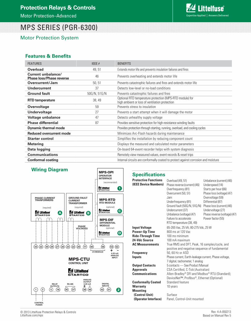
Wiring Diagram
A BC
D
1
2
SpecificationsProtective Functions (IEEE Device Numbers)
Input Voltage 65-265 Vac, 25 VA; 80-275 Vdc, 25 WPower-Up Time 800 ms at 120 VacRide-Through Time 100 ms minimum24-Vdc Source 100 mA maximumAC Measurements True RMS and DFT, Peak, 16 samples/cycle, and positive and negative sequence of fundamentalFrequency 50, 60 Hz or ASDInputs Phase current, Earth-leakage current, Phase voltage, 7 digital, tachometer, 1 analogOutput Contacts 5 contacts — See Product ManualApprovals CSA Certified, C-Tick (Australian)Communications Allen-Bradley® DFI and Modbus® RTU (Standard); DeviceNet™, Profibus®, Ethernet (Optional)Conformally Coated Standard featureWarranty 10 years Mounting (Control Unit) Surface (Operator Interface) Panel, Control-Unit mounted
Overload (49, 51)Phase reverse (current) (46)Overfrequency (81)Overcurrent (50, 51)JamUnderfrequency (81)Ground fault (50G/N, 51G/N)Undercurrent (37)Unbalance (voltage) (47)Failure to accelerateRTD temperature (38, 49)
Unbalance (current) (46)Underspeed (14)Starts per hour (66)Phase loss (voltage) (47)Overvoltage (59)Differential (87)Phase loss (current) (46)Undervoltage (27)Phase reverse (voltage) (47)Power factor (55)
Features & BenefitsFEATURES IEEE # BENEFITS
Overload 49, 51 Extends motor life and prevents insulation failures and firesCurrent unbalance/ Phase loss/Phase reverse 46 Prevents overheating and extends motor life
Overcurrent/Jam 50, 51 Prevents catastrophic failures and fires and extends motor lifeUndercurrent 37 Detects low-level or no-load conditionsGround fault 50G/N, 51G/N Prevents catastrophic failures and fires
RTD temperature 38, 49 Optional RTD temperature protection (MPS-RTD module) for high ambient or loss of ventilation protection
Overvoltage 59 Prevents stress to insulationUndervoltage 27 Prevents a start attempt when it will damage the motorVoltage unbalance 47 Detects unhealthy supply voltagePhase differential 87 Provides sensitive protection for high-resistance winding faultsDynamic thermal mode Provides protection through starting, running, overload, and cooling cyclesReduced overcurrent mode Minimizes Arc-Flash hazards during maintenanceStarter control Simplifies the installation by reducing component countMetering Displays the measured and calculated motor parametersData logging On-board 64-event recorder helps with system diagnosisCommunications Remotely view measured values, event records & reset tripsConformal coating Internal circuits are conformally coated to protect against corrosion and moisture
MPS SERIES (PGR-6300)Motor Protection System
Rev: 4-A-050213Based on Manual Rev 5