mr model - instrumart...installation installing the transmitter 1 disconnect the electrical power...
TRANSCRIPT

Flow Transmitter
MR Model
XMT-UM-00498-EN-04 (March 2018) User Manual

CONTENTSIntroduction� � � � � � � � � � � � � � � � � � � � � � � � � � � � � � � � � � � � � � � � � � � � � � � � � � � � � � � � � � � 3Safety Information� � � � � � � � � � � � � � � � � � � � � � � � � � � � � � � � � � � � � � � � � � � � � � � � � � � � � � � 3Unpacking and Inspection � � � � � � � � � � � � � � � � � � � � � � � � � � � � � � � � � � � � � � � � � � � � � � � � � 3Installation� � � � � � � � � � � � � � � � � � � � � � � � � � � � � � � � � � � � � � � � � � � � � � � � � � � � � � � � � � � � 4
Installation Recommendations � � � � � � � � � � � � � � � � � � � � � � � � � � � � � � � � � � � � � � � � � � � 5Installing the Transmitter � � � � � � � � � � � � � � � � � � � � � � � � � � � � � � � � � � � � � � � � � � � � � � � 6
Electrical Connections � � � � � � � � � � � � � � � � � � � � � � � � � � � � � � � � � � � � � � � � � � � � � � � � � � � � 7Wiring Configurations � � � � � � � � � � � � � � � � � � � � � � � � � � � � � � � � � � � � � � � � � � � � � � � � � 8Cover Removal/Reinstallation � � � � � � � � � � � � � � � � � � � � � � � � � � � � � � � � � � � � � � � � � � � � 9
Operation � � � � � � � � � � � � � � � � � � � � � � � � � � � � � � � � � � � � � � � � � � � � � � � � � � � � � � � � � � � 10Operating the Meter � � � � � � � � � � � � � � � � � � � � � � � � � � � � � � � � � � � � � � � � � � � � � � � � � 10Normal Operation (RUN) Mode � � � � � � � � � � � � � � � � � � � � � � � � � � � � � � � � � � � � � � � � � � 10Programming Operation (PROGRAM) Mode � � � � � � � � � � � � � � � � � � � � � � � � � � � � � � � � � � 11Programming Flowchart for Water (Includes Water-Based Liquids) � � � � � � � � � � � � � � � � � � � 12Programming Flowchart for Oil (Includes Petroleum-Based, Phosphate Ester and Caustic/API Oil) � � � � � � � � � � � � � � � � � � � � � � � � � � � � � � � � � � � � � � � � � � � � � � � � � � � � � � � � � � � � � � 13Programming Flowchart for Air/Gases (Includes Caustic/Corrosive Gases) � � � � � � � � � � � � � � � 14
Programming Procedures � � � � � � � � � � � � � � � � � � � � � � � � � � � � � � � � � � � � � � � � � � � � � � � � � 15List Item Selection Procedure � � � � � � � � � � � � � � � � � � � � � � � � � � � � � � � � � � � � � � � � � � � 15Numeric Value Entry Procedure � � � � � � � � � � � � � � � � � � � � � � � � � � � � � � � � � � � � � � � � � � 15Programming Flowcharts� � � � � � � � � � � � � � � � � � � � � � � � � � � � � � � � � � � � � � � � � � � � � � 16
Cartridge Components � � � � � � � � � � � � � � � � � � � � � � � � � � � � � � � � � � � � � � � � � � � � � � � � � � � 20Maintenance � � � � � � � � � � � � � � � � � � � � � � � � � � � � � � � � � � � � � � � � � � � � � � � � � � � � � � � � � 21
Cartridge Cleaning � � � � � � � � � � � � � � � � � � � � � � � � � � � � � � � � � � � � � � � � � � � � � � � � � � 21Inspection � � � � � � � � � � � � � � � � � � � � � � � � � � � � � � � � � � � � � � � � � � � � � � � � � � � � � � � 22
Troubleshooting � � � � � � � � � � � � � � � � � � � � � � � � � � � � � � � � � � � � � � � � � � � � � � � � � � � � � � � 23No LCD Display � � � � � � � � � � � � � � � � � � � � � � � � � � � � � � � � � � � � � � � � � � � � � � � � � � � � 23No Rate or Total Displayed � � � � � � � � � � � � � � � � � � � � � � � � � � � � � � � � � � � � � � � � � � � � � 23Unstable Flow Reading � � � � � � � � � � � � � � � � � � � � � � � � � � � � � � � � � � � � � � � � � � � � � � � 23
Application Information � � � � � � � � � � � � � � � � � � � � � � � � � � � � � � � � � � � � � � � � � � � � � � � � � � 23Liquid � � � � � � � � � � � � � � � � � � � � � � � � � � � � � � � � � � � � � � � � � � � � � � � � � � � � � � � � � � 23Pneumatic � � � � � � � � � � � � � � � � � � � � � � � � � � � � � � � � � � � � � � � � � � � � � � � � � � � � � � � 24
Fluid Selection Charts� � � � � � � � � � � � � � � � � � � � � � � � � � � � � � � � � � � � � � � � � � � � � � � � � � � � 25Liquids� � � � � � � � � � � � � � � � � � � � � � � � � � � � � � � � � � � � � � � � � � � � � � � � � � � � � � � � � � 25Gas � � � � � � � � � � � � � � � � � � � � � � � � � � � � � � � � � � � � � � � � � � � � � � � � � � � � � � � � � � � � 26
Flow vs Pressure Drop � � � � � � � � � � � � � � � � � � � � � � � � � � � � � � � � � � � � � � � � � � � � � � � � � � � 27Petroleum Fluids � � � � � � � � � � � � � � � � � � � � � � � � � � � � � � � � � � � � � � � � � � � � � � � � � � � 27Phosphate Ester� � � � � � � � � � � � � � � � � � � � � � � � � � � � � � � � � � � � � � � � � � � � � � � � � � � � 28API Oil � � � � � � � � � � � � � � � � � � � � � � � � � � � � � � � � � � � � � � � � � � � � � � � � � � � � � � � � � � 29Water-Based Fluids � � � � � � � � � � � � � � � � � � � � � � � � � � � � � � � � � � � � � � � � � � � � � � � � � � 30Water � � � � � � � � � � � � � � � � � � � � � � � � � � � � � � � � � � � � � � � � � � � � � � � � � � � � � � � � � � 31Caustic and Corrosive Liquids � � � � � � � � � � � � � � � � � � � � � � � � � � � � � � � � � � � � � � � � � � � 32Air/Compressed Gases � � � � � � � � � � � � � � � � � � � � � � � � � � � � � � � � � � � � � � � � � � � � � � � 33Air/Caustic and Corrosive Gases� � � � � � � � � � � � � � � � � � � � � � � � � � � � � � � � � � � � � � � � � � 34
Specifications � � � � � � � � � � � � � � � � � � � � � � � � � � � � � � � � � � � � � � � � � � � � � � � � � � � � � � � � � 35Materials � � � � � � � � � � � � � � � � � � � � � � � � � � � � � � � � � � � � � � � � � � � � � � � � � � � � � � � � � � � � 36Dimensions � � � � � � � � � � � � � � � � � � � � � � � � � � � � � � � � � � � � � � � � � � � � � � � � � � � � � � � � � � 38
Flow Transmitter, MR Model
Page ii March 2018XMT-UM-00498-EN-04
Introduction
INTRODUCTIONThe MR flow transmitter is a state-of-the-art, microprocessor based variable area flow meter� It combines the rugged proven technology of a piston-type, variable area flow meter with solid-state circuitry including:
• Non-contact sensor electronics
• Electronic signal conditioning circuit
• Digital flow rate and total indication
• Proportional analog output
The product is sealed against industrial contamination by a NEMA 12 and 13 (IP 52/54) rated enclosure and is available for either liquid or gas service�
The MR flow transmitter is capable of calculating and displaying both flow rate and total accumulated flow� The flow rate and total flow can be displayed in any of the user selectable measurement units� The monitor’s large 8 digit numeric liquid crystal display makes extended range viewing practical� The second 8 character alphanumeric display provides for selectable units viewing in RUN mode and prompts for variables in PROGRAM mode�
All MR flow transmitters come pre-calibrated from the factory� However, the unit may be adjusted by the user to meet specific system requirements� Calibration parameters are included for:
• Specific gravity compensation (all fluids)
• Viscosity compensation (petroleum-based fluids)
• Pressure and temperature compensation (pneumatic applications)
All meters include an analog output that can be configured for 0…5V DC, 0…10V DC, or 4…20 mA current loop�
SAFETY INFORMATIONThe installation of this flow meter must comply with all applicable federal, state, and local rules, regulations, and codes�
Failure to read and follow these instructions can lead to misapplication or misuse of this product, resulting in personal injury and damage to equipment�
UNPACKING AND INSPECTIONUpon opening the shipping container, visually inspect the product and applicable accessories for any physical damage such as scratches, loose or broken parts, or any other sign of damage that may have occurred during shipment�
OTEE:N If damage is found, request an inspection by the carrier's agent within 48 hours of delivery and file a claim with the carries� A claim for equipment damage in transit is the sole responsibility of the purchaser�
Page 3 March 2018 XMT-UM-00498-EN-04
Installation
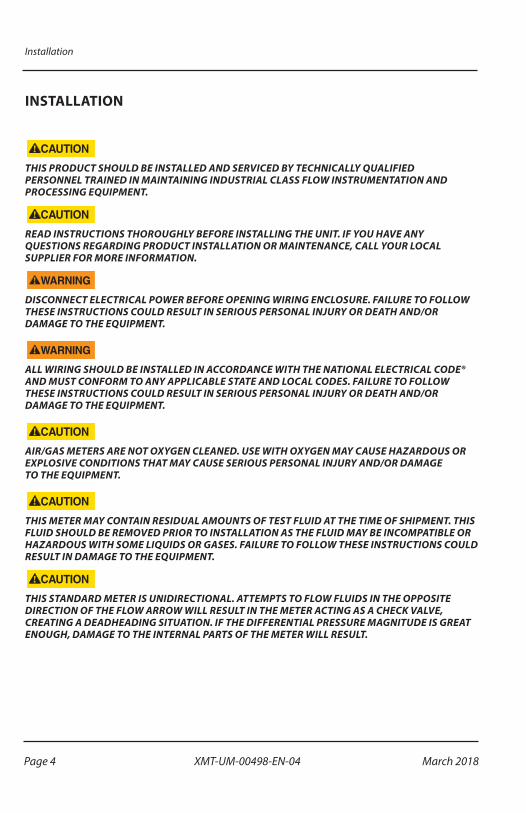
INSTALLATION
THIS PRODUCT SHOULD BE INSTALLED AND SERVICED BY TECHNICALLY QUALIFIED PERSONNEL TRAINED IN MAINTAINING INDUSTRIAL CLASS FLOW INSTRUMENTATION AND PROCESSING EQUIPMENT.
READ INSTRUCTIONS THOROUGHLY BEFORE INSTALLING THE UNIT. IF YOU HAVE ANY QUESTIONS REGARDING PRODUCT INSTALLATION OR MAINTENANCE, CALL YOUR LOCAL SUPPLIER FOR MORE INFORMATION.
DISCONNECT ELECTRICAL POWER BEFORE OPENING WIRING ENCLOSURE. FAILURE TO FOLLOW THESE INSTRUCTIONS COULD RESULT IN SERIOUS PERSONAL INJURY OR DEATH AND/OR DAMAGE TO THE EQUIPMENT.
ALL WIRING SHOULD BE INSTALLED IN ACCORDANCE WITH THE NATIONAL ELECTRICAL CODE® AND MUST CONFORM TO ANY APPLICABLE STATE AND LOCAL CODES. FAILURE TO FOLLOW THESE INSTRUCTIONS COULD RESULT IN SERIOUS PERSONAL INJURY OR DEATH AND/OR DAMAGE TO THE EQUIPMENT.
AIR/GAS METERS ARE NOT OXYGEN CLEANED. USE WITH OXYGEN MAY CAUSE HAZARDOUS OR EXPLOSIVE CONDITIONS THAT MAY CAUSE SERIOUS PERSONAL INJURY AND/OR DAMAGE TO THE EQUIPMENT.
THIS METER MAY CONTAIN RESIDUAL AMOUNTS OF TEST FLUID AT THE TIME OF SHIPMENT. THIS FLUID SHOULD BE REMOVED PRIOR TO INSTALLATION AS THE FLUID MAY BE INCOMPATIBLE OR HAZARDOUS WITH SOME LIQUIDS OR GASES. FAILURE TO FOLLOW THESE INSTRUCTIONS COULD RESULT IN DAMAGE TO THE EQUIPMENT.
THIS STANDARD METER IS UNIDIRECTIONAL. ATTEMPTS TO FLOW FLUIDS IN THE OPPOSITE DIRECTION OF THE FLOW ARROW WILL RESULT IN THE METER ACTING AS A CHECK VALVE, CREATING A DEADHEADING SITUATION. IF THE DIFFERENTIAL PRESSURE MAGNITUDE IS GREAT ENOUGH, DAMAGE TO THE INTERNAL PARTS OF THE METER WILL RESULT.
Page 4 March 2018XMT-UM-00498-EN-04
Installation
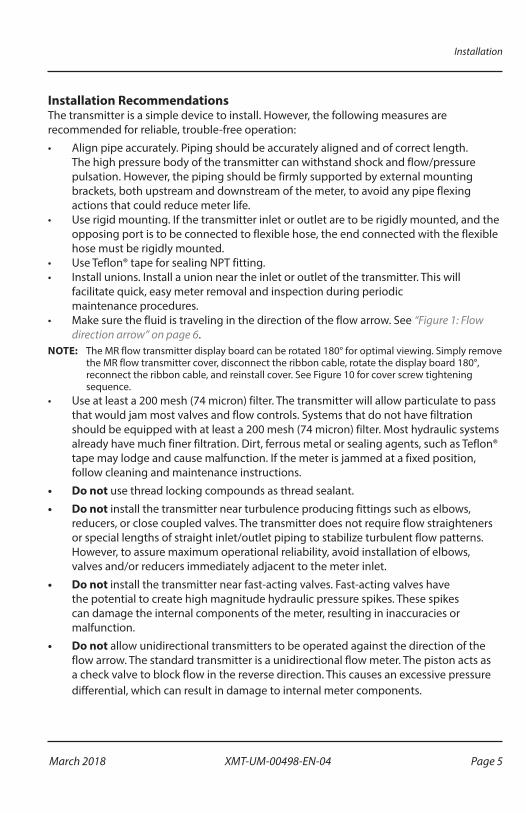
Installation RecommendationsThe transmitter is a simple device to install� However, the following measures are recommended for reliable, trouble-free operation:
• Align pipe accurately� Piping should be accurately aligned and of correct length� The high pressure body of the transmitter can withstand shock and flow/pressure pulsation� However, the piping should be firmly supported by external mounting brackets, both upstream and downstream of the meter, to avoid any pipe flexing actions that could reduce meter life�
• Use rigid mounting� If the transmitter inlet or outlet are to be rigidly mounted, and the opposing port is to be connected to flexible hose, the end connected with the flexible hose must be rigidly mounted�
• Use Teflon® tape for sealing NPT fitting�• Install unions� Install a union near the inlet or outlet of the transmitter� This will
facilitate quick, easy meter removal and inspection during periodic maintenance procedures�
• Make sure the fluid is traveling in the direction of the flow arrow� See “Figure 1: Flow direction arrow” on page 6�
OTEE:N The MR flow transmitter display board can be rotated 180° for optimal viewing� Simply remove the MR flow transmitter cover, disconnect the ribbon cable, rotate the display board 180°, reconnect the ribbon cable, and reinstall cover� See Figure 10 for cover screw tightening sequence�
• Use at least a 200 mesh (74 micron) filter� The transmitter will allow particulate to pass that would jam most valves and flow controls� Systems that do not have filtration should be equipped with at least a 200 mesh (74 micron) filter� Most hydraulic systems already have much finer filtration� Dirt, ferrous metal or sealing agents, such as Teflon® tape may lodge and cause malfunction� If the meter is jammed at a fixed position, follow cleaning and maintenance instructions�
• Do not use thread locking compounds as thread sealant�
• Do not install the transmitter near turbulence producing fittings such as elbows, reducers, or close coupled valves� The transmitter does not require flow straighteners or special lengths of straight inlet/outlet piping to stabilize turbulent flow patterns� However, to assure maximum operational reliability, avoid installation of elbows, valves and/or reducers immediately adjacent to the meter inlet�
• Do not install the transmitter near fast-acting valves� Fast-acting valves have the potential to create high magnitude hydraulic pressure spikes� These spikes can damage the internal components of the meter, resulting in inaccuracies or malfunction�
• Do not allow unidirectional transmitters to be operated against the direction of the flow arrow� The standard transmitter is a unidirectional flow meter� The piston acts as a check valve to block flow in the reverse direction� This causes an excessive pressure differential, which can result in damage to internal meter components�
Page 5 March 2018 XMT-UM-00498-EN-04

Installation
Installing the Transmitter
1� Disconnect the electrical power from the target system before making or changing any transmitter connections�
2� Use 0�05 A fast-acting fuse if non-current limited power sources are used�
3� Terminate cable shield connection at either DC ground or earth ground�4� Mount the transmitter so fluid is traveling in the direction of the flow arrow�
Flow Direction Arrow
Flow Inlet
Figure 1: Flow direction arrow
5� Install unit in desired location� Use wrench on transmitter flats to hold the unit in place during installation� DO NOT TURN the transmitter using the wrench�
6� After installation, rotate the transmitter by hand to view the display� 7� Capture the zero flow position on the meter cone using the ZERO CAPTURE procedure�
Place wrench on transmitter flats on the same side plumbing is being tightened�
Never place wrench on transmitter flats opposite plumbing being tightened�
Rotate transmitter by hand only to view flow scale� Never use wrench on flats to rotate transmitter�
Figure 2: Installing and rotating the transmitter
Page 6 March 2018XMT-UM-00498-EN-04
Electrical Connections
ELECTRICAL CONNECTIONS
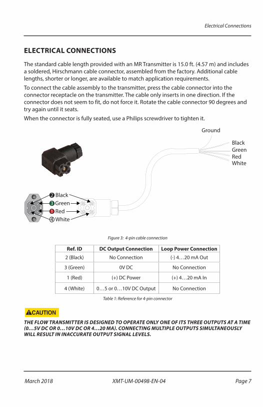
The standard cable length provided with an MR Transmitter is 15�0 ft� (4�57 m) and includes a soldered, Hirschmann cable connector, assembled from the factory� Additional cable lengths, shorter or longer, are available to match application requirements�
To connect the cable assembly to the transmitter, press the cable connector into the connector receptacle on the transmitter� The cable only inserts in one direction� If the connector does not seem to fit, do not force it� Rotate the cable connector 90 degrees and try again until it seats�
When the connector is fully seated, use a Philips screwdriver to tighten it�
BlackGreenRedWhite
Ground
Black2
Green3
White4Red1
Figure 3: 4-pin cable connection
Ref. ID DC Output Connection Loop Power Connection
2 (Black) No Connection (-) 4…20 mA Out
3 (Green) 0V DC No Connection
1 (Red) (+) DC Power (+) 4…20 mA In
4 (White) 0…5 or 0…10V DC Output No Connection
Table 1: Reference for 4-pin connector
THE FLOW TRANSMITTER IS DESIGNED TO OPERATE ONLY ONE OF ITS THREE OUTPUTS AT A TIME (0…5V DC OR 0…10V DC OR 4…20 MA). CONNECTING MULTIPLE OUTPUTS SIMULTANEOUSLY WILL RESULT IN INACCURATE OUTPUT SIGNAL LEVELS.
Page 7 March 2018 XMT-UM-00498-EN-04
Electrical Connections
MEN
UEN
TER
RUN
PRO
GRA
MRE
LAY
1RE
LAY
2
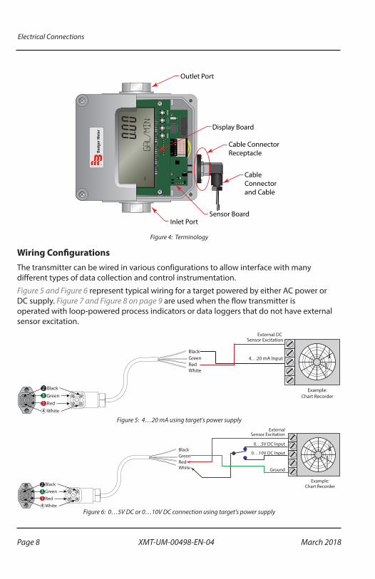
Outlet Port
Display Board
CableConnectorand Cable
Sensor BoardInlet Port
Cable ConnectorReceptacle
Figure 4: Terminology
Wiring ConfigurationsThe transmitter can be wired in various configurations to allow interface with many different types of data collection and control instrumentation�
Figure 5 and Figure 6 represent typical wiring for a target powered by either AC power or DC supply� Figure 7 and Figure 8 on page 9 are used when the flow transmitter is operated with loop-powered process indicators or data loggers that do not have external sensor excitation�
External DC Sensor Excitation
4. . .20 mA Input
Example:Chart Recorder
BlackGreenRedWhite
BlackGreen
WhiteRed
2
13
4
Figure 5: 4…20 mA using target's power supply
BlackGreenRedWhite
Black2Green
WhiteRed
ExternalSensor Excitation
0. . .10V DC Input
Ground
0. . .5V DC Input
Example:Chart Recorder
13
4Figure 6: 0…5V DC or 0…10V DC connection using target's power supply
Page 8 March 2018XMT-UM-00498-EN-04
Electrical Connections
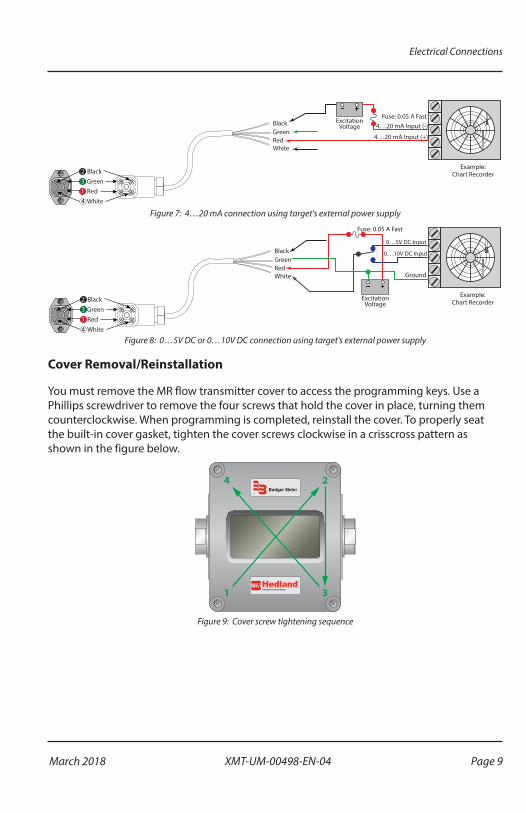
BlackGreenRedWhite
Black2Green
WhiteRed
Example:Chart Recorder
13
4
Fuse: 0.05 A FastExcitation
Voltage
4. . .20 mA Input (+)
4. . .20 mA Input (-)
Figure 7: 4…20 mA connection using target's external power supply
BlackGreenRedWhite
Black2Green
WhiteRed
Example:Chart Recorder
13
4
Fuse: 0.05 A Fast
ExcitationVoltage
0. . .10V DC Input
Ground
0. . .5V DC Input
Figure 8: 0…5V DC or 0…10V DC connection using target's external power supply
Cover Removal/Reinstallation
You must remove the MR flow transmitter cover to access the programming keys� Use a Phillips screwdriver to remove the four screws that hold the cover in place, turning them counterclockwise� When programming is completed, reinstall the cover� To properly seat the built-in cover gasket, tighten the cover screws clockwise in a crisscross pattern as shown in the figure below�
Figure 9: Cover screw tightening sequence
Page 9 March 2018 XMT-UM-00498-EN-04
Operation
OPERATION
Operating the MeterThe monitor has two modes of operation, referred to as RUN mode and PROGRAM mode as indicated on the display screen readout� Normal operation will be in the run mode� To access the program mode, press MENU until the first programming screen "DISPLAY" appears�
OTEE:N "PROGRAM" appears on left side of display�
After programming the meter, a password may be entered to prevent unauthorized access to programming�
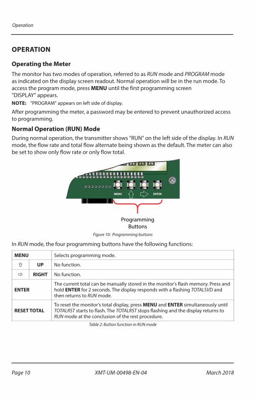
Normal Operation (RUN) ModeDuring normal operation, the transmitter shows "RUN" on the left side of the display� In RUN mode, the flow rate and total flow alternate being shown as the default� The meter can also be set to show only flow rate or only flow total�
MENU ENTER
ProgrammingButtons
Figure 10: Programming buttons
In RUN mode, the four programming buttons have the following functions:
MENU Selects programming mode�
ñ UP No function�
ð RIGHT No function�
ENTERThe current total can be manually stored in the monitor's flash memory� Press and hold ENTER for 2 seconds� The display responds with a flashing TOTALSVD and then returns to RUN mode�
RESET TOTALTo reset the monitor's total display, press MENU and ENTER simultaneously until TOTALRST starts to flash� The TOTALRST stops flashing and the display returns to RUN mode at the conclusion of the rest procedure�
Table 2: Button function in RUN mode
Page 10 March 2018XMT-UM-00498-EN-04
Operation
Programming Operation (PROGRAM) ModeThe Program mode lets you change the configuration and adjust the calibration of the meter� The MR flow transmitter has two types of configuration changes accessible in program mode:
• View or change selections from a pre-defined list
• View or change numeric entries
In Program mode, the four programming buttons have the following functions:
MENU Enters and exits programming mode� Press MENU once to change to programming mode� The mode indicator on the display changes from "RUN" to "PROGRAM�"
ñ Scrolls through the configuration choices in a bottom-to-top order� For numeric setup, this button increments numeric values�
ð Scrolls through the configuration choices in a top-to-bottom order� For numeric setup, this button moves the active digit to the right�
ENTER Used to enter menus, to change configurations and to save programming information�
Table 3: Button function in PROGRAM mode
OTEE:N When any input value exceeds the meter’s capabilities, the LIMIT indicator begins to flash, indicating an invalid entry� Press ENTER once to return to the entry screen to reenter the value�
Page 11 March 2018 XMT-UM-00498-EN-04

Operation
Programming Flowchart for Water (Includes Water-Based Liquids)
Basic Menu
AdvancedFunction
Sub Menu
Shape Key
Flow 4 mA(Full Flow Rate)
Numeric Entry
Flow 20 mA(Flow at 20 mA)
Numeric Entry
4-20 Test(Test Output)
Single Digit Increments
Flow 0V(Flow at 0 Volts)
Numeric Entry
Flow 5V(Flow at 5 Volts)
Numeric Entry
0-5 Test(Test Output)
Single Digit Increments
Flow 0V(Flow at 0 Volts)
Numeric Entry
Flow 10V(Flow at 10V)
Numeric Entry
0-10 Test(Test Output)
Single Digit Increments
START
DisplayRateTotalBothTest
SecondMinute
HourDay
RateInt(Rate Time interval)
RateUnt(Rate Unit)Gallons
LitersMillion Gallons
Cubic FeetCubic MetersMillion Liters
Acre FeetOil Barrel
Liquor BarrelPounds
Kilograms
TotalUnt(Totalizer Unit)
GallonsLiters
Million GallonsCubic Feet
Cubic MetersMillion Liters
Acre FeetOil Barrel
Liquor BarrelPounds
Kilograms
Spec Gr(Speci�c Gravity)
Numeric Entry
Out Mode(Output Mode)
4-20 mA0-5V DC
0-10V DC
FullFlow(Full Flow Rate)
Numeric Entry
Zero Cap(Zero Capture)
NO YES
Numeric Entry
Damping(Display Damping)
Cal Out?(Calibrate Output?)
NO YES
Numeric Entry
Password(Password)
NO YES
Res D�t(Reset to Default)
Totl Exp(Totalizer Exponent)
E-2 = × 0.01E-1 = × 0.1
E0 = × 1E1 = × 10
E2 = × 100E3 = × 1000
E4 = × 10,000E5 = × 100,000
E6 = × 1,000,000
Figure 11: Water flowchart
Page 12 March 2018XMT-UM-00498-EN-04
Operation
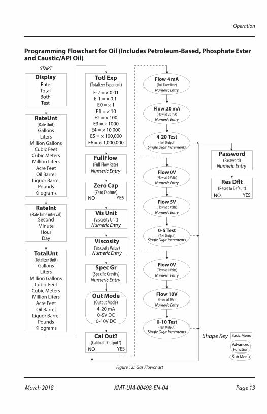
Programming Flowchart for Oil (Includes Petroleum-Based, Phosphate Ester and Caustic/API Oil)
Basic Menu
AdvancedFunction
Sub Menu
Shape Key
Flow 4 mA(Full Flow Rate)
Numeric Entry
Flow 20 mA(Flow at 20 mA)
Numeric Entry
4-20 Test(Test Output)
Single Digit Increments
Flow 0V(Flow at 0 Volts)
Numeric Entry
Flow 5V(Flow at 5 Volts)
Numeric Entry
0-5 Test(Test Output)
Single Digit Increments
Flow 0V(Flow at 0 Volts)
Numeric Entry
Flow 10V(Flow at 10V)
Numeric Entry
0-10 Test(Test Output)
Single Digit Increments
START
DisplayRateTotalBothTest
SecondMinute
HourDay
RateInt(Rate Time interval)
RateUnt(Rate Unit)Gallons
LitersMillion Gallons
Cubic FeetCubic MetersMillion Liters
Acre FeetOil Barrel
Liquor BarrelPounds
Kilograms
TotalUnt(Totalizer Unit)
GallonsLiters
Million GallonsCubic Feet
Cubic MetersMillion Liters
Acre FeetOil Barrel
Liquor BarrelPounds
Kilograms
Out Mode(Output Mode)
4-20 mA0-5V DC
0-10V DC
FullFlow(Full Flow Rate)
Numeric Entry
Zero Cap(Zero Capture)
NO YES
Cal Out?(Calibrate Output?)
NO YES
Numeric Entry
Password(Password)
NO YES
Res D�t(Reset to Default)
Totl Exp(Totalizer Exponent)
E-2 = × 0.01E-1 = × 0.1
E0 = × 1E1 = × 10
E2 = × 100E3 = × 1000
E4 = × 10,000E5 = × 100,000
E6 = × 1,000,000
Vis Unit(Viscosity Unit)
Numeric Entry
Viscosity(Viscosity Value)
Numeric Entry
Spec Gr(Speci�c Gravity)
Numeric Entry
Figure 12: Gas Flowchart
Page 13 March 2018 XMT-UM-00498-EN-04

Operation
Programming Flowchart for Air/Gases (Includes Caustic/Corrosive Gases)
Basic Menu
AdvancedFunction
Sub Menu
Tmp Unit(Temperature Units)
Degree FDegree C
Out Mode(Output Mode)
4-20 mA0-5V DC
0-10V DC
Shape Key
PSI Bar
Pres Unit(Pressure Units)
Cal Out?(Calibrate Output?)
NO YES
Numeric Entry
Password(Password)
NO YES
Flow 4 mA(Full Flow Rate)Numeric Entry
Flow 20 mA(Flow at 20 mA)
Numeric Entry
4-20 Test(Test Output)
Single Digit Increments
Flow 0V(Flow at 0 Volts)
Numeric Entry
Flow 5V(Flow at 5 Volts)
Numeric Entry
0-5 Test(Test Output)
Single Digit Increments
Flow 0V(Flow at 0 Volts)
Numeric Entry
Flow 10V(Flow at 10V)Numeric Entry
0-10 Test(Test Output)
Single Digit Increments
Res D�t(Reset to Default)
Op Pres(Operating Pressure)Numeric Entry
Op Temp(Operating Temperature)
Numeric Entry
Sp Grav(Speci�c Gravity)
Numeric Entry
START
DisplayRateTotalBothTest
SecondMinute
HourDay
RateInt(Rate Time interval)
RateUnt(Rate Unit)Gallons
LitersMillion Gallons
Cubic FeetCubic MetersMillion Liters
Acre FeetOil Barrel
Liquor BarrelPounds
Kilograms
TotalUnt(Totalizer Unit)
GallonsLiters
Million GallonsCubic Feet
Cubic MetersMillion Liters
Acre FeetOil Barrel
Liquor BarrelPounds
Kilograms
FullFlow(Full Flow Rate)
Numeric Entry
Zero Cap(Zero Capture)
NO YES
Totl Exp(Totalizer Exponent)
E-2 = × 0.01E-1 = × 0.1
E0 = × 1E1 = × 10
E2 = × 100E3 = × 1000
E4 = × 10,000E5 = × 100,000
E6 = × 1,000,000
Figure 13: Air/gases flowchart
Page 14 March 2018XMT-UM-00498-EN-04

Programming Procedures
PROGRAMMING PROCEDURES
The MR flow transmitter is programmed at the factory according to the specifications provided at the time of order� No further programming is required unless a change has occurred in the original specifications�
List Item Selection ProcedureOTEE:N If you are already in PROGRAM mode and the selection to view or change is displayed,
proceed to step 3 below� If you are in PROGRAM mode and the selection to view or change is not displayed, press ñ or ð and repeat pressing until the required selection appears, then proceed to step 3�
1� Press MENU� "PROGRAM" appears in the lower left corner and "DISPLAY" appears�
2� Press ñ or ð to move to the required selection�3� Press ENTER to view the current selection�
4� If the current selection is correct, press ENTER to confirm� The unit automatically advances�
5� To change the current selection, press ñ or ð to scroll through the available choices� Press ENTER to confirm the selection� The unit automatically advances�
6� To exit programming, press MENU� The display changes to RUN mode�
Numeric Value Entry ProcedureOTEE:N If you are already in PROGRAM mode and the selection to view or change is displayed, proceed
to step 3 below� If you are in PROGRAM mode and the selection to view or change is not displayed, press ñ or ð and repeat pressing until the required selection appears, then proceed to step 3�
1� Press MENU� "PROGRAM" appears in the lower left corner and "DISPLAY" appears�
2� Press ñ or ð to move to the required selection� The current numeric value for the selection appears in the upper area of the display�
3� If the displayed value is correct, press ENTER� The left-most programmable number flashes� Press ENTER again to confirm and keep the current setting� The unit automatically advances�
4� To change the current selection, press ENTER� The left-most programmable number flashes� Use ñ to scroll through the digits 0…9 and change the flashing digit to the required value� Use ð to move the active digit to the right� Continue using ñ and ð until all required digits are selected�
5� Press ENTER to confirm the selection� The unit automatically advances�
6� To exit programming mode, press MENU� The display changes to RUN mode�
Page 15 March 2018 XMT-UM-00498-EN-04

Programming Procedures
Programming Flowcharts
See the following programming flowcharts for the menu structure of the MR flow transmitter and the available configuration selections:
• "Programming Flowchart for Water (Includes Water-Based Liquids)" on page 12
• "Programming Flowchart for Oil (Includes Petroleum-Based, Phosphate Ester and Caustic/API Oil)" on page 13
• "Programming Flowchart for Air/Gases (Includes Caustic/Corrosive Gases)" on page 14
Basic Programming Descriptions
Display Mode (Display)In Display mode, the meter can display RATE (flow rate) or TOTAL (total accumulated flow) or alternate between BOTH rate and total� Edit with the "List Item Selection Procedure" on page 15�
Rate Units of Measure (RATE UNT)The meter lets you select from many common rate units� Edit with the "List Item Selection Procedure" on page 15�
Rate (Time) Interval (RATE INT)The meter lets you select intervals based on time� Edit with the "List Item Selection Procedure" on page 15�
Total Units of Measure (TOTL UNT)To display the Total Flow, you must first select the engineering units for the total� The monitor allows the choice of many common totalization units� Edit with the "List Item Selection Procedure" on page 15�
Total Display Multiplier (TOTL EXP)The meter can accumulate the flow total in multiples of ten� For example, if the most desirable totalization unit is 1000 gallons, the monitor can easily be set up for this requirement� Once back in RUN mode, every time the total display increments by one digit the actual total would be an additional 1000 gallons� At 1000 total gallons the total display would read 1, at 3000 gallons the total display would read 3� This feature allows the unit to accumulate totals that would exceed the 8-digit display capacity� Table 2 lists the available selection choices� Edit with the "List Item Selection Procedure" on page 15�
Page 16 March 2018XMT-UM-00498-EN-04

Programming Procedures
Exponent Totalizer Multiplier
E-2 × 0�01 (÷100)
E-1 × 0�1 (÷100)
E0 × 1 (no multiplier)
E1 × 10
E2 × 100
E3 × 1000
E4 × 10,000
E5 × 100,000
E6 × 1,000,000
Table 4: Total flow units
Full Flow Rate (FULL FLOW)The Full Flow Rate parameter is used to span the meter� Edit with the "Numeric Value Entry Procedure" on page 15�
Zero Capture (ZERO CAP)You must set the zero position of the meter cone when installing the meter� To capture the zero calibration position, press ENTER at the ZERO CAP prompt� "NO" displays� Press either arrow key to change to "YES", then press ENTER to capture zero�
Viscosity Units (VIS UNIT) (Displayed for OIL meters only)The Viscosity Units parameter is used in conjunction with Viscosity to perform viscosity correction for oil applications� You can select the viscosity units, SUS or cSt� Edit with the "List Item Selection Procedure" on page 15�
Viscosity (VISCOSITY) (Displayed for OIL meters only)Viscosity is used in conjunction with Viscosity Units to perform viscosity correction for oil applications� Enter the viscosity in either SUS or cSt, depending on the viscosity units selected for the oil being used� Edit with the "Numeric Value Entry Procedure" on page 15�
Operating Pressure Unit (PRES UNIT) (Displayed for GAS Meters Only)The Operating Pressure Units parameter is used in conjunction with Operating Pressure in gas applications to compensate for the actual pressure being measured at the meter� The operating pressure unit selections are Bar or PSI� Edit with the "List Item Selection Procedure" on page 15�
Page 17 March 2018 XMT-UM-00498-EN-04

Programming Procedures
Operating Pressure (OP PRES) (Displayed for GAS Meters Only)The Operating Pressure parameter is used in conjunction with Operating Pressure Units in gas applications to compensate for the actual pressure being measured at the meter� Enter the operating pressure in either Bar or PSI units, depending on the Operating Pressure Units selected� Edit with the "List Item Selection Procedure" on page 15�
Operating Temperature Unit (TMP UNIT) (Displayed for GAS Meters Only)The Operating Temperature Units parameter is used in conjunction with Operating Temperature in gas applications to compensate for the actual temperature of the gas being measured at the meter� The meter allows the selection of the operating temperature units, °F or °C� Edit with the "List Item Selection Procedure" on page 15�
Operating Temperature (OP TEMP) (Displayed for GAS Meters Only)The Operating Temperature parameter is used in conjunction with Operating Temperature Units in gas applications to compensate for the actual temperature of the gas being measured at the meter� Enter the operating temperature in either °F or °C, depending on the Operating Temperature Units selected� Edit with the "List Item Selection Procedure" on page 15�
Specific Gravity Correction Factor (SP GRAV)The Specific Gravity parameter is used to compensate for the specific gravity of the liquid or gas being measured with the meter� Edit with the "List Item Selection Procedure" on page 15�
Damping (DAMPING)The Damping factor is increased to enhance the stability of the flow readings� Damping values are decreased to allow the flow meter to react faster to changing values of flow� This parameter can range from 0…99� The factory default is 0� Edit with the "List Item Selection Procedure" on page 15�
Output Mode (OUT MODE)The MR flow transmitter has three analog output modes:
• 4…20 mA Output Signal
• 0…5V DC Output Signal
• 0…10V DC Output Signal
The Output Mode required is determined by the type of peripheral device being connected to the MR flow transmitter� Edit with the "List Item Selection Procedure" on page 15�
OTEE:N Setup prompts and descriptors for configuring and calibrating the analog output correspond to the selected Output Mode�
Page 18 March 2018XMT-UM-00498-EN-04
Programming Procedures
Password (PASSWORD)Password protection prevents unauthorized users from changing programming information� Initially, the password is set to all zeros� Edit with the "Numeric Value Entry Procedure" on page 15�
Restore Defaults (RES DFLT)Use this feature to restore factory calibration data� To restore factory calibration data, select YES, then press ENTER�
Advanced Programming DescriptionsAdvanced programming allows for re-configuring the analog output� Calibration of the analog output is preset at the factory, but can be changed to customize calibration for your installation�
To access the Advanced Programming options, press and hold MENU for approximately 3 seconds until "DISPLAY" shows on the display panel� The programming menus begin with the DISPLAY mode and continue as described above through Output Mode (OUT MODE)�
After you enter Output Mode, Advanced Programming starts with the following:
Calibrating Analog Output (CAL OUT?)OTEE:N Setup prompts and descriptors for configuring and calibrating the analog output correspond
to the output mode selected� Refer to the flowcharts on pages page 12 through page 14�
To test or change the analog output calibration:
1� At the CAL OUT? prompt press ENTER� "NO" displays�2� Press either arrow key to select YES�3� The analog output goes to its minimum output level� A numeric value between
0…4000 displays� This is an internal number used to drive the analog output�4� To increase the analog output signal level, press ñ� To decrease the analog output
signal level, press ð�5� Press ENTER to store the setting�6� The analog output goes to its maximum output level� A numeric value between
0…4000 displays� This is an internal number used to drive the analog output�7� To increase the analog output signal level, press ñ� To decrease the analog output
signal level, press ð�8� Press ENTER to store the setting�9� The unit advances to the analog output test mode� The analog output goes to its
minimum output level� A numeric value of 0 displays� For test purposes, the analog output signal can be run up or down in increments of 1 milliamp or 1 volt, depending on the OUT MODE selected�
10� To increase the analog output signal level, press ñ� To decrease the analog output signal level, press ð�
11� Press ENTER to exit the analog calibration mode�
12� The unit automatically advances to the PASSWORD feature�
Page 19 March 2018 XMT-UM-00498-EN-04
Cartridge Components
Password (PASSWORD)Password protection prevents unauthorized users from changing programming information� Initially, the password is set to all zeros� Edit with the "Numeric Value Entry Procedure" on page 20�
Restore Defaults (RES DFLT)Use this feature to restore factory calibration data� To restore factory calibration data, select YES, then press ENTER�
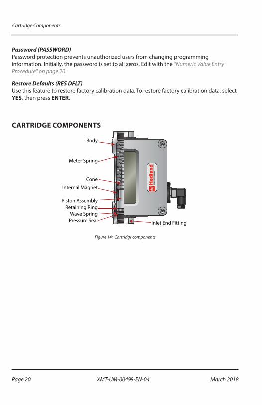
CARTRIDGE COMPONENTS
Body
Inlet End Fitting
Retaining Ring
Meter Spring
Cone
Internal Magnet
Piston Assembly
Wave SpringPressure Seal
Figure 14: Cartridge components
Page 20 March 2018XMT-UM-00498-EN-04
Maintenance
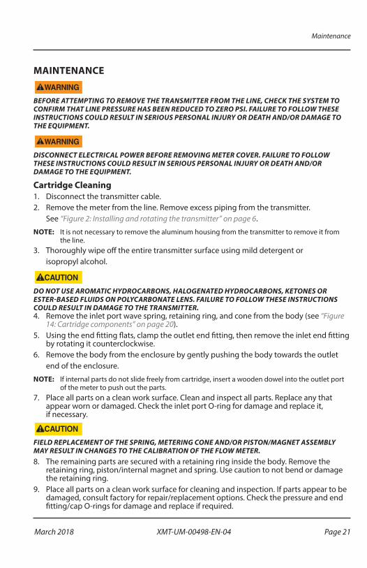
MAINTENANCE
BEFORE ATTEMPTING TO REMOVE THE TRANSMITTER FROM THE LINE, CHECK THE SYSTEM TO CONFIRM THAT LINE PRESSURE HAS BEEN REDUCED TO ZERO PSI. FAILURE TO FOLLOW THESE INSTRUCTIONS COULD RESULT IN SERIOUS PERSONAL INJURY OR DEATH AND/OR DAMAGE TO THE EQUIPMENT.
DISCONNECT ELECTRICAL POWER BEFORE REMOVING METER COVER. FAILURE TO FOLLOW THESE INSTRUCTIONS COULD RESULT IN SERIOUS PERSONAL INJURY OR DEATH AND/OR DAMAGE TO THE EQUIPMENT.
Cartridge Cleaning1� Disconnect the transmitter cable�2� Remove the meter from the line� Remove excess piping from the transmitter�
See “Figure 2: Installing and rotating the transmitter” on page 6�
OTEE:N It is not necessary to remove the aluminum housing from the transmitter to remove it from the line�
3� Thoroughly wipe off the entire transmitter surface using mild detergent or isopropyl alcohol�
DO NOT USE AROMATIC HYDROCARBONS, HALOGENATED HYDROCARBONS, KETONES OR ESTER-BASED FLUIDS ON POLYCARBONATE LENS. FAILURE TO FOLLOW THESE INSTRUCTIONS COULD RESULT IN DAMAGE TO THE TRANSMITTER.4� Remove the inlet port wave spring, retaining ring, and cone from the body (see “Figure
14: Cartridge components” on page 20)�5� Using the end fitting flats, clamp the outlet end fitting, then remove the inlet end fitting
by rotating it counterclockwise�6� Remove the body from the enclosure by gently pushing the body towards the outlet
end of the enclosure�
OTEE:N If internal parts do not slide freely from cartridge, insert a wooden dowel into the outlet port of the meter to push out the parts�
7� Place all parts on a clean work surface� Clean and inspect all parts� Replace any that appear worn or damaged� Check the inlet port O-ring for damage and replace it, if necessary�
FIELD REPLACEMENT OF THE SPRING, METERING CONE AND/OR PISTON/MAGNET ASSEMBLY MAY RESULT IN CHANGES TO THE CALIBRATION OF THE FLOW METER.8� The remaining parts are secured with a retaining ring inside the body� Remove the
retaining ring, piston/internal magnet and spring� Use caution to not bend or damage the retaining ring�
9� Place all parts on a clean work surface for cleaning and inspection� If parts appear to be damaged, consult factory for repair/replacement options� Check the pressure and end fitting/cap O-rings for damage and replace if required�
Page 21 March 2018 XMT-UM-00498-EN-04

Maintenance
10� In reverse order, gently reassemble all parts back to their original configuration�11� Reinstall the spring, followed by the piston/internal magnet and then the retaining ring�12� Reinstall the cone/spider plate assembly and retaining spring, and secure with the inlet
end fitting� Secure the lid and ensure proper seating of the cover gasket by tightening the screws in a crisscross pattern� See “Figure 9: Cover screw tightening sequence” on page 9�
13� Reinstall the flow meter in the line� Reconnect the transmitter cable�
InspectionInspect the transmitter at least once a year� The environment and frequency of use should determine a schedule for maintenance checks�
• Perform visual, electrical, and mechanical checks on all components�
• Visually check for undue heating evidence, such as discolored wires or other components, damaged or worn parts, or leakage evidence, such as water or corrosion in the interior�
• Make sure all electrical connections are clean and tight and that the device is wired properly�
Page 22 March 2018XMT-UM-00498-EN-04

Troubleshooting
TROUBLESHOOTINGNo LCD Display• For 4…20 mA operation, check for current flow in the loop�
• Check polarity of the current loop connections for proper orientation�
• For 0…5V or 0…10V operation, check for proper voltage being supplied to the unit�
• Check polarity of the supply voltage�
No Rate or Total Displayed• Check flow meter body and internal components for debris� Piston should move inside
the tube freely�
• Check setup programming of flow meter�
Unstable Flow ReadingThis usually indicates pulsing or oscillation in the actual flow� Increase the DAMPING parameter to increase the filtering in order to provide a more stable display reading�
APPLICATION INFORMATIONLiquid
Viscosity Effect (SUS/cSt)The design uses a precision machined, sharp- edged orifice and biasing calibration spring that assures operating stability and accuracy over the wide viscosity range common to many fluids� Generally, high flow models of each meter size provide good accuracy over a viscosity range of 40…500 SUS (4�2…109 cSt)�
Density Effect (Specific Gravity)Any fluid density change from stated standards has a proportional effect on meter accuracy� Corrections for more or less dense fluids can be made to standard scales using the following correction factor:
1 0.Speci�c Gravity
For water/water-based meters
0 876.Speci�c Gravity
For petroleum-based meters
Page 23 March 2018 XMT-UM-00498-EN-04

Application Information
PneumaticOTEE:N Pressure and temperature readings must be taken at the flow meter inlet to ensure accurate
correction factors�The pneumatic flow meter is calibrated for air in standard cubic feet per minute (scfm) at 1�0 s�g� (70° F @ 100 psi), and liter per second (lps) at 1�0 s�g� (21° C @ 6�9 bar)�
PressureGauge Air Bleed O�
to Equipment
PressureSource
AdjustableValve
FlowMeter
Temp
Figure 15: System schematic
Determine Flow Rates Using Different Pressures and Temperatures
scfm actualscfm indicated
f x f x f( )
( )=
1 32
Where f1 = Conversion Factor for Pressuref2 = Conversion Factor for Temperaturef3 = Conversion Factor for Specific Gravity
psig 25 50 75 100 125 150 175 200 225 250
BAR 1�7 3�5 5�2 6�9 8�6 10�4 12�1 13�8 15�5 17�2
kPa 172 345 517 689 862 1034 1207 1379 1551 1724
f1 1�700 1�331 1�131 1�00 0�902 0�835 0�778 0�731 0�692 0�658
fkPa
1790 857
101 357=
+.
.f
BAR1
7 9141 014
=+
..
fpsig
1114 7
14 7=
+.
.
Table 5: Temperature Correction Factor (f1) Operating Pressure
°F 10 30 50 70 90 110 130 150 170 190
°C –12�2 –1�1 9�9 21�0 32�1 43 54 65 76 88
f2 0�942 0�962 0�981 1�00 1�018 1�037 1�055 1�072 1�090 1�107
fF
2460
530=
+ °f
C2
273293
=+ °
Table 6: Temperature Correction Factor (f2)
f Sp Gr3 = . .
Table 7: Specific Gravity Correction Factor (f3)
OTEE:N Table 6 is included to show the correction algorithms include in the program to perform pressure, temperature, and specific gravity corrections� When configuring the MR Model, enter the actual operating pressure, temperature, and specific gravity values, not the correction factors�
Page 24 March 2018XMT-UM-00498-EN-04
Fluid Selection Charts
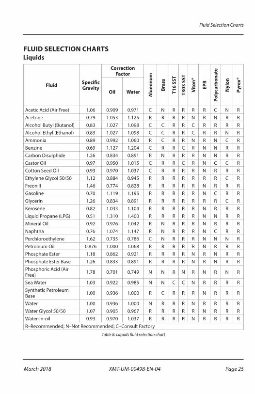
FLUID SELECTION CHARTSLiquids
Fluid Specific Gravity
Correction Factor
Alu
min
um
Bras
s
T16
SST
T303
SST
Vito
n®
EPR
Poly
carb
onat
e
Nyl
on
Pyre
x®
Oil Water
Acetic Acid (Air Free) 1�06 0�909 0�971 C N R R R R C N RAcetone 0�79 1�053 1�125 R R R R N R N R RAlcohol Butyl (Butanol) 0�83 1�027 1�098 C C R R C R R R RAlcohol Ethyl (Ethanol) 0�83 1�027 1�098 C C R R C R R N RAmmonia 0�89 0�992 1�060 R C R R N R N C RBenzine 0�69 1�127 1�204 C R R C R N N R RCarbon Disulphide 1�26 0�834 0�891 R N R R R N N R RCastor Oil 0�97 0�950 1�015 C R R C R N C C RCotton Seed Oil 0�93 0�970 1�037 C R R R R N R R REthylene Glycol 50/50 1�12 0�884 0�945 R R R R R R R C RFreon II 1�46 0�774 0�828 R R R R R N R R RGasoline 0�70 1�119 1�195 R R R R R N C R RGlycerin 1�26 0�834 0�891 R R R R R R R C RKerosene 0�82 1�033 1�104 R R R R R N R R RLiquid Propane (LPG) 0�51 1�310 1�400 R R R R R N N R RMineral Oil 0�92 0�976 1�042 R N R R R N R R RNaphtha 0�76 1�074 1�147 R N R R R N C R RPerchloroethylene 1�62 0�735 0�786 C N R R R N N N RPetroleum Oil 0�876 1�000 1�068 R R R R R N R R RPhosphate Ester 1�18 0�862 0�921 R R R R N R N R RPhosphate Ester Base 1�26 0�833 0�891 R R R R N R N R RPhosphoric Acid (Air Free) 1�78 0�701 0�749 N N R N R N R N R
Sea Water 1�03 0�922 0�985 N N C C N R R R RSynthetic Petroleum Base 1�00 0�936 1�000 R C R R R N R R R
Water 1�00 0�936 1�000 N R R R N R R R RWater Glycol 50/50 1�07 0�905 0�967 R R R R R N R R RWater-in-oil 0�93 0�970 1�037 R R R R N R R R RR–Recommended; N–Not Recommended; C–Consult Factory
Table 8: Liquids fluid selection chart
Page 25 March 2018 XMT-UM-00498-EN-04

Fluid Selection Charts
Gas
Fluid Specific Gravity
Corr
ecti
on F
acto
r
Alu
min
um
Bras
s
T16
SST
T303
SST
Vito
n®
EPR
Poly
carb
onat
e
Nyl
on
Pyre
x®
Air 1�0 1�000 R R R R R R R R R
Argon (A) 1�38 1�175 R R R R R R R R R
Carbon Dioxide (CO2) 1�53 1�237 R R R R R R R R R
Freon 11 (CCI3F) 4�92 2�218 R R R R R R R R R
Freon 12 (CCI2F) 4�26 2�060 R R R R R R R R R
Helium (HE) 0�14 0�374 R R R R R R R R R
Hydrogen (H2) 0�07 0�265 R R R R R R R R R
Natural Gas 0�60 0�775 C C R C R N C R R
Nitrogen (N2) 0�97 0�985 C C R R R R C R R
Oxygen (O2) 1�10 1�049 R R R R R R R R R
Propane C3H8) 1�57 1�253 R R R R R N N R R
R–Recommended; N–Not Recommended; C–Consult Factory
Table 9: Gaseous fluid selection chart
Page 26 March 2018XMT-UM-00498-EN-04

Flow vs Pressure Drop
FLOW VS PRESSURE DROPPetroleum Fluids
3/4"/1" Reverse Flow
0.2-2.00.5-5.0
1-10
2-20
3-30
4-40
1/4" .20-2.0
.10-1.0
.05-.50.02-.20
FLOW, GPM
PRES
SURE
DRO
P, PS
I
FLOW, GPM
PRES
SURE
DRO
P, PS
I
1-1/4"/1-1/2" Reverse Flow
3-305-50
10-75
10-100
10-150
FLOW, GPM
PRES
SURE
DRO
P, PS
I
3.0" 20-30010-200
FLOW, GPM
PRES
SURE
DRO
P, PS
I
1-1/4"/1-1/2"10-150
10-100
10-75
5-50
3-30
FLOW, GPM
PRES
SURE
DRO
P, PS
I
1/2" 1-15
1-10
0.5-5.0
0.2-2.00.1-1.0
FLOW, GPM
PRES
SURE
DRO
P, PS
I
FLOW, GPM
PRES
SURE
DRO
P, PS
I
3/4"/ 1"5-50
4-40
3-30
2-20
1/2" Reverse Flow
0.1-1.0
0.5-5.00.2-2.0
1-10
1-15
FLOW, GPM
PRES
SURE
DRO
P, PS
I
0.2-2.0
0
5
10
0 10
1-10
0.5-5.0
Figure 16: Petroleum fluids pressure drop charts
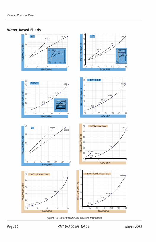
The pressure drop curves are valid for fluids with density and viscosity similar to factory test fluids� Fluids, especially with higher viscosity than these test fluids, will yield a higher pressure drop through the flow meter and piping system per a given flow volume�
A system needs adequate fluidic horsepower to move the system fluid at a prescribed rate at a pressure adequate to overcome all pressure reducing devices, including the flow meter�
Page 27 March 2018 XMT-UM-00498-EN-04

Flow vs Pressure Drop
Phosphate Ester
3/4"/ 1"
2-20
3-30
5-50
4-40
1-10
FLOW, GPM
PRES
SURE
DRO
P, P
SI
1-1/4" / 1-1/2" 10-150
10-100
10-75
5-50
3-30
FLOW, GPM
PRES
SURE
DRO
P, P
SI
1/2" 1-15
1-10
0.5-5.0
FLOW, GPM
PRES
SURE
DRO
P, P
SI
FLOW, GPM
PRES
SURE
DRO
P, P
SI
1/4" 0.20-2.0
0.10-1.0
1/2" Reverse Flow
0.1-1.00.5-5.0
0.2-2.0
1-10
1-15
FLOW, GPM
PRES
SURE
DRO
P, P
SI
3/4"/1" Reverse Flow
0.2-2.00.5-5.0
1-10
2-20
3-30
4-40
FLOW, GPM
PRES
SURE
DRO
P, P
SI
1-1/4"/1-1/2" Reverse Flow
3-305-50
10-75
10-100
10-150
FLOW, GPM
PRES
SURE
DRO
P, P
SI
0 1 2 2.50
2
4 0.1-1.00.2-2.0
0 1 2 3 540
2
4
6
0.2-2.0
0.5-5.0
0
2
4
6
0.50.0
.02-.20
.05-.50
Figure 17: Phosphate ester pressure drop charts
Page 28 March 2018XMT-UM-00498-EN-04

Flow vs Pressure Drop
API Oil
FLOW, GPM
PRES
SURE
DRO
P, PS
I
1/4"
.10-1.0
.20-2.0 1-15
1-10
0.5-5.0
0.2-2.0
FLOW, GPM
PRES
SURE
DRO
P, PS
I
1/2"
3/4" / 1" 4-40
3-30
2-20
FLOW, GPM
PRES
SURE
DRO
P, PS
I
1-1/4"/ 1-1/2"
10-100
10-75
5-50
3-30
FLOW, GPM
PRES
SURE
DRO
P, PS
I
Figure 18: API oil pressure drop charts
Page 29 March 2018 XMT-UM-00498-EN-04
Flow vs Pressure Drop
Water-Based Fluids
1/2" Reverse Flow
0.1-1.00.5-5.0
0.2-2.0
1-10
1-15
FLOW, GPM
PRES
SURE
DRO
P, P
SI
1-1/4"/1-1/2" Reverse Flow
3-305-50
10-75
10-100
10-150
FLOW, GPM
PRES
SURE
DRO
P, P
SI
3/4"/1" Reverse Flow
0.2-2.0 0.5-5.01-10
2-20
3-30
4-40
FLOW, GPM
PRES
SURE
DRO
P, P
SI
3"20-275
20-180
FLOW, GPM
PRES
SURE
DRO
P, P
SI
1-1/4"/ 1-1/2"
10-150
10-100
10-75
5-50
3-30
FLOW, GPM
PRES
SURE
DRO
P, P
SI
1-15
1-10
FLOW, GPM
PRES
SURE
DRO
P, P
SI
1/2"
0.5-5.0
1/4" .10 -1.0
.20-2.0
FLOW, GPM
PRES
SURE
DRO
P, P
SI
.05-.50
0.2-2.0 0.1-1.0
0.2-2.0
3/4" / 1" 5-50
4-40
3-30
2-20
FLOW, GPM
PRES
SURE
DRO
P, P
SI
0.5-5.01-10
0.2-2.0
Figure 19: Water-based fluids pressure drop charts
Page 30 March 2018XMT-UM-00498-EN-04

Flow vs Pressure Drop
Water
15-150
10-100
5-50
3"
FLOW, GPM
PRES
SURE
DRO
P, P
SI
1-1/4"/ 1-1/2"
10-150
10-100
10-75
5-50
3-30
FLOW, GPM
PRES
SURE
DRO
P, P
SI
1/4" .10 -1.0
.20-2.0
FLOW, GPM
PRES
SURE
DRO
P, P
SI
1-15
1-10
FLOW, GPM
PRES
SURE
DRO
P, P
SI
1/2"
0.5-5.0
3/4" / 1" 5-50
4-40
3-30
2-20
FLOW, GPM
PRES
SURE
DRO
P, P
SI
0.5-5.01-10
0.2-2.0
.05-.50
0.2-2.0 0.1-1.0
0.2-2.0
Figure 20: Water pressure drop charts
Page 31 March 2018 XMT-UM-00498-EN-04

Flow vs Pressure Drop
Caustic and Corrosive Liquids
1-1/4"/ 1-1/2"
10-100
10-75
5-50
3-30
FLOW, GPM
PRES
SURE
DRO
P, P
SI
1/4" .10 -1.0
.20-2.0
FLOW, GPM
PRES
SURE
DRO
P, P
SI
3/4" / 1"
4-40
3-30
2-20
FLOW, GPM
PRES
SURE
DRO
P, P
SI
1-15
1-10
FLOW, GPM
PRES
SURE
DRO
P, P
SI
1/2"
0.5-5.0
0.2-2.0
0.5-5.01-10
0.1-2.0
Figure 21: Caustic and corrosive liquids pressure drop charts
Page 32 March 2018XMT-UM-00498-EN-04
Flow vs Pressure Drop
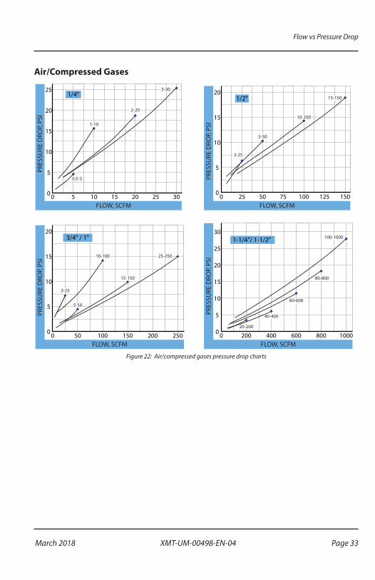
Air/Compressed Gases
FLOW, SCFM
PRES
SURE
DRO
P, PS
I
0
5
10
15
20
10-100 25-250
15-150
3-25
5-50
3/4" / 1"
0 10050 150 200 250FLOW, SCFM
PRES
SURE
DRO
P, PS
I
1-1/4"/ 1-1/2"
0
5
10
15
20
25
30
0 400200 600 800 100020-200
60-600
80-800
100-1000
40-400
FLOW, SCFMPR
ESSU
RE D
ROP,
PSI
1/2"
0
5
10
15
20
0 5025 75 100 125 150
3-25
15-150
10-100
5-50
FLOW, SCFM
PRES
SURE
DRO
P, PS
I
0
5
10
15
20
25
0 105 15 20 25 30
2-20
1-10
0.5-5
3-301/4"
Figure 22: Air/compressed gases pressure drop charts
Page 33 March 2018 XMT-UM-00498-EN-04

Flow vs Pressure Drop
Air/Caustic and Corrosive Gases
FLOW, SCFM
PRES
SURE
DRO
P, PS
I
0
5
10
15
20
10-100 25-250
15-150
3-25
5-50
3/4" / 1"
0 10050 150 200 250FLOW, SCFM
PRES
SURE
DRO
P, PS
I
1-1/4"/ 1-1/2"
0
5
10
15
20
25
30
0 400200 600 800 100020-200
60-600
80-800
100-1000
40-400
FLOW, SCFMPR
ESSU
RE D
ROP,
PSI
1/2"
0
5
10
15
20
0 5025 75 100 125 150
3-25
15-150
10-100
5-50
FLOW, SCFM
PRES
SURE
DRO
P, PS
I
0
5
10
15
20
25
0 105 15 20 25 30
2-20
3-301/4"
Figure 23: Air/caustic and corrosive gases pressure drop charts
Page 34 March 2018XMT-UM-00498-EN-04

Specifications
SPECIFICATIONSEnclosure Rating
NEMA 12 & 13 (equivalent to IP52 & 54)
Accuracy ± 2% of full scaleRepeatability ± 1%Threads SAE J1926/1, NPTF ANSI B2�2, BSPP IS01179Temperature Range –20…240° F (–29…116° C)
Pressure Rating
Aluminum/Brass Operating
Liquids: 3500 psi/241 bar maximum (3:1 safety factor) Gases: 1000 psi/69 bar maximum (10:1 safety factor)
Stainless Steel Operating
Liquids (1/4…1/2 in�): 6000 psi/414 bar maximum (3:1 safety factor) Liquids (3/4…1-1/2 in�): 5000 psi/345 bar maximum (3:1 safety factor) Gases: 1500 psi/103 bar maximum (10:1 safety factor)
CRN Models
Liquids (1/4 in or SAE 6) 5000 psi Liquids (1/2 in� or SAE 10) 3000 psi Liquids (3/4 in� or SAE 12…16) 2500 psi Liquids (1-1/4…1-1/2 in� or SAE 20…24) 2450 psi Gases (all sizes): 1500 psi
Power Requirement
0…5V DC Output: 10…30V DC @ 0�75W maximum0…10V DC Output: 12…30V DC @ 0�75W maximum4…20 mA Output: loop…powered, 30V DC maximum
Power Consumption 25 mA maximum
Analog Outputs0…5V DC and 0…10V DC into 10,000 Ohms minimum4…20 mA into 1000 Ohms maximum
Circuit Protection Reverse polarity and current limiting
Transmission Distance
4…20 mA limited by cable resistance0…5V DC and 0…10V DC 1000 feet (300 m) maximum
Isolation Inherently isolated from the piping system
DisplayFixed or toggle modes of operation for rate and totalizer display8 digit, 0�70 in� high numeric display for rate and total8 digit, 0�35 in� high alphanumeric display for units and setup
Temperature Drift 50 ppm / °C (max)
Analog OutputE: Resolution 1:4000Transient Over-Voltages Category 3, in accordance with IEC 664
Pollution Degree Category 2, in accordance with IEC 664
Approvals EMC Directive 89/336/EECTable 10: Unit specifications
Page 35 March 2018 XMT-UM-00498-EN-04
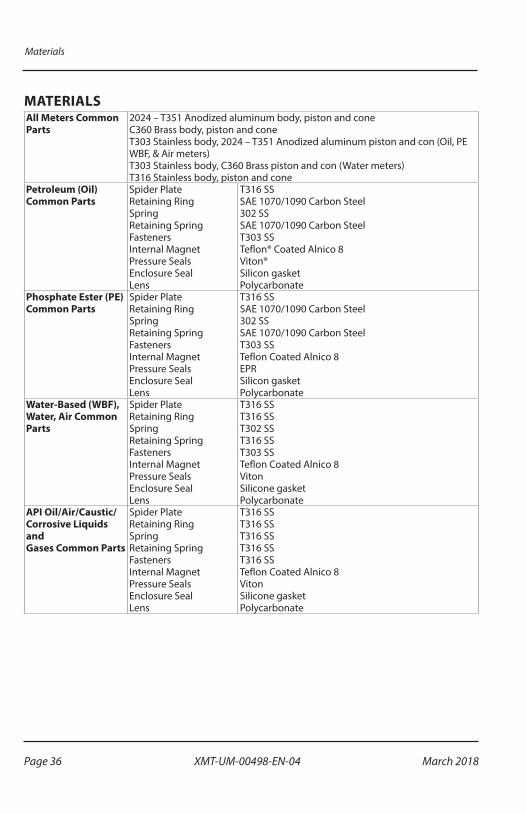
Materials
MATERIALSAll Meters Common Parts
2024 – T351 Anodized aluminum body, piston and cone C360 Brass body, piston and cone T303 Stainless body, 2024 – T351 Anodized aluminum piston and con (Oil, PE WBF, & Air meters) T303 Stainless body, C360 Brass piston and con (Water meters) T316 Stainless body, piston and cone
Petroleum (Oil) Common Parts
Spider Plate Retaining Ring Spring Retaining Spring Fasteners Internal Magnet Pressure Seals Enclosure Seal Lens
T316 SS SAE 1070/1090 Carbon Steel 302 SS SAE 1070/1090 Carbon Steel T303 SS Teflon® Coated Alnico 8 Viton® Silicon gasket Polycarbonate
Phosphate Ester (PE) Common Parts
Spider Plate Retaining Ring Spring Retaining Spring Fasteners Internal Magnet Pressure Seals Enclosure Seal Lens
T316 SS SAE 1070/1090 Carbon Steel 302 SS SAE 1070/1090 Carbon Steel T303 SS Teflon Coated Alnico 8 EPR Silicon gasket Polycarbonate
Water-Based (WBF), Water, Air Common Parts
Spider Plate Retaining Ring Spring Retaining Spring Fasteners Internal Magnet Pressure Seals Enclosure Seal Lens
T316 SS T316 SS T302 SS T316 SS T303 SS Teflon Coated Alnico 8 Viton Silicone gasket Polycarbonate
API Oil/Air/Caustic/Corrosive Liquids and Gases Common Parts
Spider Plate Retaining Ring Spring Retaining Spring Fasteners Internal Magnet Pressure Seals Enclosure Seal Lens
T316 SS T316 SS T316 SS T316 SS T316 SS Teflon Coated Alnico 8 Viton Silicone gasket Polycarbonate
Page 36 March 2018XMT-UM-00498-EN-04

Materials
High Cycle ApplicationsE: Pressure Fatigue Rating
Per NFPA/T2�6�1 R1 - 1991, C/90, the method of verifying rated fatigue pressure (or establishing the rated burst pressure, or both) of the pressure containing envelope conforms to NFPA/T2�6�1 R1, Fluid power systems and products – Method for verifying the fatigue and establishing the burst pressure ratings of the pressure containing envelope of a metal fluid power component�
Meter Size Aluminum Brass Stainless SteelRFP* Cycles RFP* Cycles RFP* Cycles
1/4 2000 1×10⁶ ** 3000 1×10⁶
1/2 2000 1×10⁶ ** 3000 1×10⁶
3/4 1500 1×10⁶ ** 3000 1×10⁶
1 1500 1×10⁶ ** 3000 1×10⁶
1-1/4 1000 1×10⁶ ** 3000 1×10⁶
1500 70×103 ** 3000 1×10⁶
1-1/2 1000 1×10⁶ ** 3000 1×10⁶
1500 70×103 ** 3000 1×10⁶
*RFP = Rated Fatigue Pressure **Consult FactoryTable 11: Materials specifications
Page 37 March 2018 XMT-UM-00498-EN-04

Dimensions
DIMENSIONS
C
K
A
D
B
F E
G
J
H
I
Figure 24: Dimensions
Nominal Port Size
B C D E F G H I J KLength
in. (mm)Length
in. (mm)Length
in. (mm)Width
in. (mm)Width
in. (mm)Width
in. (mm)Cable
in. (mm)Depth
in. (mm)Offset
in. (mm)Hole Dia. in. (mm)
1/4 in. SAE 6
6.60 (167.64)
5.27 (133.86)
6.92 (175.77)
6.00 (152.40)
3.60 (91.44)
3.00 (76.20)
4.20 (107)
2.94 (74.68)
1.46 (37.08)
0.28 (7.11)
1/2 in. SAE 10
6.60 (167.64)
5.27 (133.86)
6.92 (175.77)
6.00 (152.40)
3.60 (91.44)
3.00 (76.20)
4.20 (107)
2.94 (74.68)
1.46 (37.08)
0.28 (7.11)
3/4 in. SAE 12
7.20 (182.88)
5.27 (133.86)
6.92 (175.77)
6.00 (152.40)
3.60 (91.44)
3.00 (76.20)
4.20 (107)
2.94 (74.68)
1.46 (37.08)
0.28 (7.11)
1 in. SAE 16
7.20 (182.88)
5.27 (133.86)
6.92 (175.77)
6.00 (152.40)
3.60 (91.44)
3.00 (76.20)
4.20 (107)
2.94 (74.68)
1.46 (37.08)
0.28 (7.11)
1-1/4 in. SAE 20
12.20 (309.88)
10.68 (271.27)
11.65 (295.91)
7.63 (193.80)
4.84 (122.94)
3.82 (97.03)
5.02 (128)
4.50 (114.30)
2.20 (55.88)
0.28 (7.11)
1-1/2 in. SAE 24
12.20 (309.88)
10.68 (271.27)
11.65 (295.91)
7.63 (193.80)
4.84 (122.94)
3.82 (97.03)
5.02 (128)
4.50 (114.30)
2.20 (55.88)
0.28 (7.11)
Table 12: Dimensions
OTEE:N Fractional sizes apply to NPT and BSP configurations�
Page 38 March 2018XMT-UM-00498-EN-04

INTENTIONAL BLANK PAGE
User Manual
March 2018 XMT-UM-00498-EN-04 Page 39

Flow Transmitter, MR Model
The Americas | Badger Meter | 4545 West Brown Deer Rd | PO Box 245036 | Milwaukee, WI 53224-9536 | 800-876-3837 | 414-355-0400México | Badger Meter de las Americas, S.A. de C.V. | Pedro Luis Ogazón N°32 | Esq. Angelina N°24 | Colonia Guadalupe Inn | CP 01050 | México, DF | México | +52-55-5662-0882Europe, Eastern Europe Branch Office (for Poland, Latvia, Lithuania, Estonia, Ukraine, Belarus) | Badger Meter Europe | ul. Korfantego 6 | 44-193 Knurów | Poland | +48-32-236-8787Europe, Middle East and Africa | Badger Meter Europa GmbH | Nurtinger Str 76 | 72639 Neuffen | Germany | +49-7025-9208-0Europe, Middle East Branch Office | Badger Meter Europe | PO Box 341442 | Dubai Silicon Oasis, Head Quarter Building, Wing C, Office #C209 | Dubai / UAE | +971-4-371 2503 Slovakia | Badger Meter Slovakia s.r.o. | Racianska 109/B | 831 02 Bratislava, Slovakia | +421-2-44 63 83 01Asia Pacific | Badger Meter | 80 Marine Parade Rd | 21-06 Parkway Parade | Singapore 449269 | +65-63464836China | Badger Meter | 7-1202 | 99 Hangzhong Road | Minhang District | Shanghai | China 201101 | +86-21-5763 5412Switzerland | Badger Meter Swiss AG | Mittelholzerstrasse 8 | 3006 Bern | Switzerland | +41-31-932 01 11 Legacy Document Number: 04-VAM-UM-00232 HLIT 300
www.badgermeter.com
Hedland is a registered trademark of Badger Meter� All other trademarks appearing in this document are the property of their respective entities� Due to continuous research, product improvements and enhancements, Badger Meter reserves the right to change product or system specifications without notice, except to the extent an outstanding contractual obligation exists� © 2018 Badger Meter, Inc� All rights reserved�
Control. Manage. Optimize.