2645abestand.renaultsafrane.nl/bestanden/phii mr302 b54.pdf · lower nuts (b) and the upper nut (c)...
TRANSCRIPT

77 11 191 856 NOVEMBER 1996 Edition Anglaise
"The repair methods given by the manufacturer in this document are based on thetechnical specifications current when it was prepared.
The methods may be modified as a result of changes by the manufacturer in theproduction of the various component units and accessories from which his vehiclesare constructed".
All copyrights reserved by the Régie Nationale des Usines Renault.
Copying or translating, in part or in full, of this document or use of the service partreference numbering system is forbidden without the prior written authority of theRégie Nationale des Usines Renault S.A.
C Renault S.A.1996
B54 F/G/L/M
N.T. 2645A
Basic manual: M.R. 302
This technical note describes the special electricalfeatures of "new generation" Safrane vehicles.

81-1
Contents
Light units
Direction indicators
Fog lamps
Height adjustment
80-1
80-3
80-4
80-5
Rear lights
PagesPages
REAR AND INTERIOR LIGHTING
FRONT LIGHTS80
81
Changing the siren
Changing the alarm computer
Diagram
Fault-finding
Fault-finding - XR25 fiche
Introduction
Interpretation of XR25 bargraphs
Conformity check
Customer complaints
Fault-finding charts
82-6
82-6
82-8
82-9
82-10
82-11
82-12
82-29
82-30
82-31
ALARMDescription
Location
Operation - Alarm visible andaudible indicators
Arming the alarm
Disarming the alarm
Duration of operation
Disabling the "passengercompartment volumetricprotection" function
Alarm test
Perimetric detection test
Volumetric detection test
82-1
82-1
82-3
82-4
82-4
82-4
82-5
82-5
82-5
82-5
ALARM82

Contents
PagesPages
RADIO
Aerial 86-1
86
STORING THE DRIVER’S SEATPOSITION
General
Description
Recalling the position
Connection
Changing motors
Changing cables
Computer reinitialisationprocedure
Diagram
Fault-finding
Introduction
Fault-finding - XR25 fiche
Interpretation of XR25bargraphs
Customer complaints
Fault-finding charts
88-1
88-1
88-2
88-3
88-8
88-9
88-10
88-11
88-12
88-13
88-14
88-17
88-67
88-84
WIRING88
Instrument panel
Instrument panel with tripcomputer
CRUISE CONTROL
Description
Location of components
Operation
Connecting the computer
Wiring diagram
Fault-finding
Fault-finding - XR25 fiche
Interpretation of XR25bargraphs
Customer complaints
Fault-finding charts
Conformity check
83-1
83-6
83-7
83-7
83-14
83-16
83-16
83-18
83-20
83-21
83-36
83-37
83-58
INSTRUMENT PANEL83

HEADLIGHTSHeadlight units 80
REMOVAL
Disconnect the battery.
Remove:
- the direction indicators, tilting the lever torelease them,
- the radiator grille following removal of the 2bolts (3), then by sliding clips (10) and (11) inthe direction of the arrows using a screwdriver.
Move plate (12) aside slightly, then gentlydisengage the radiator grille assembly.
11237R7
11708R1
Remove the headlight unit by removing the 2lower nuts (B) and the upper nut (C) behind theheadlight unit
NOTE: if the vehicle is fitted with headlightwashers, remove the two washer jet mountingbolts following removal of the trim.
11236R1Remove the headlight unit from the front.
95009R
80-1

HEADLIGHTSHeadlight units
CONNECTION
Headlight unit connector (grey)
80SPECIAL CONDITION OF REFITTING
The headlight units must be adjusted once theyhave been fitted.
Adjustment:
Check that there is no load in the vehicle.
Set the height adjustment to 0 (A).
Then adjust the height using screw (D) and thedirection using screw (B).
Track Function
A1
A2
B1
B2
C1
C2
Spare
Side light
Earth
Dipped headlight
Spare
Main beam headlight
A
95010R1
95328R
NOTE:
- when changing bulbs, only use approved H7halogen bulbs.
- when cleaning the headlights, use a soft clothor cotton wool dampened with soapy water.Do not use alcohol based products.
80-2

HEADLIGHTSDirection indicators 80
REMOVAL - REFITTING
Remove the direction indicator light by tiltinglever (A) downwards and disengaging the lightfrom the front.
95009R1
80-3

HEADLIGHTSFog lamps 80
For vehicles fitted with front fog lamps (2).
REMOVAL
Remove the cover (1) by moving the tab in thedirection shown and then remove it from itshousing.
Remove the fog lamp mounting bolt (4).
Disconnect the connector.
REFITTING
Refit the fog lamp.
Adjust it using screw (3).
80-4

HEADLIGHTSHeight adjustment
CONNECTION
80REMOVING - REFITTING THE CONTROL
Remove the clipping assembly (A).
CONNECTION
Track Function
A1
A2
A3
B1
B2
B3
Parking light
Earth
Spare
Height adjustment control
Dipped headlights
Spare
REMOVAL - REFITTING OF THE RECEIVER UNIT
Remove the light unit (see page 80-2).
Turn the height adjustment receiver unit aquarter turn.
Dislodge the light unit ball joint.
Disengage the assembly.
Track Function
A
B
C
Earth
Adjustment control
Dipped headlights information
A
NOTE : Earth (A2) must be correct for the systemto operate correctly.
95327R95328R1
80-5

REAR AND INTERIOR LIGHTINGRear lights
NOTE: the bulbs can be changed withoutremoving the light.
81REMOVING - REFITTING WING LIGHTS
Open the flap inside the luggage compartment.
Disconnect the connector.
Remove the three mounting nuts (A).
Disengage the light from the rear.
CONNECTION
Track Function
1
2
3
4
Earth
Side light
Brake light
Direction indicator
95305R
11687R
81-1

REAR AND INTERIOR LIGHTINGRear lights 81
REMOVING - REFITTING TAILGATE LIGHTS
Open the flap.
Disconnect the light connectors.
Remove the 2 mounting bolts (A).
Unclip the light and disengage it from the rear.
CONNECTION
Track Function
1
2
3
4
Reversing light
Fog lamp
Earth
Earth
11686R1
4-way connector
Track Function
1
2
Earth
Side lights
2-way connector
81-2
REAR AND INTERIOR LIGHTINGRear lights 81
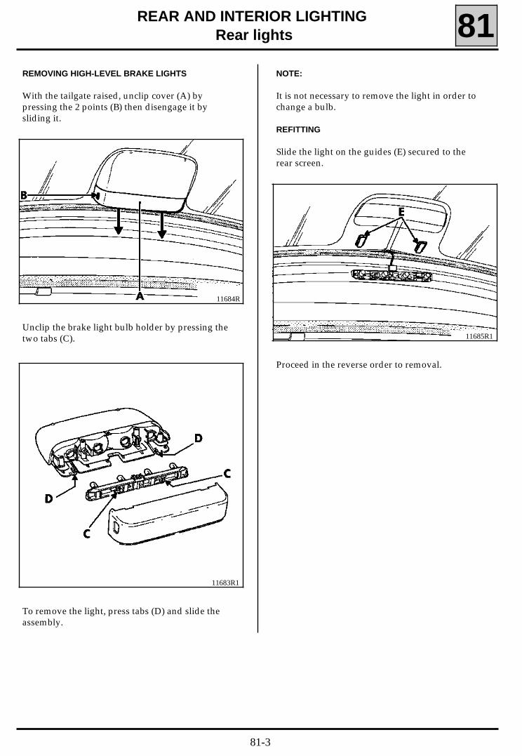
REMOVING HIGH-LEVEL BRAKE LIGHTS
With the tailgate raised, unclip cover (A) bypressing the 2 points (B) then disengage it bysliding it.
11684R
Unclip the brake light bulb holder by pressing thetwo tabs (C).
11683R1
To remove the light, press tabs (D) and slide theassembly.
NOTE:
It is not necessary to remove the light in order tochange a bulb.
REFITTING
Slide the light on the guides (E) secured to therear screen.
11685R1
Proceed in the reverse order to removal.
81-3

ALARMAlarm 82
DESCRIPTION
The security alarm is made up of:
- a self-powered siren,
- an volumetric detection computer (ultrasound),plus an alarm indicator light,
- a key-operated lock for arming or disarmingthe alarm,
- an alarm computer,
- a remote control decoding computer whichallows the alarm to be armed or disarmed.
To gain access to it, remove:
- the scuttle grille seal,
- the two wiper arms,
- the scuttle grille.
NOTE: The connector must be pulled hard in orderto disconnect the siren wiring
LOCATION OF COMPONENTS
• the self-powered siren is secured to a metalbracket to the right under the scuttle grille.
11855S
82-1

ALARMAlarm 82
• The key-operated lock for arming or disarmingthe alarm is located at the bottom of thedashboard on the passenger side. It is operatedby the ignition key.
• The volumetric detection computer is locatedon the roof console with the remote controlreceiver and the alarm indicator light.
95770-1S
11856S
WARNING:From December 1996 this lock will no longer bepresent in SAFRANE vehicles fitted with the new"duel function" decoding computer (a computerwhich combines the remote control and codedkey engine immobiliser decoding functions).
It will then be possible to disarm the alarm byswitching on the ignition (informationtransmitted by the coded key engine immobiliserreceiver ring).
It allows the alarm to be disarmed in the event ofa remote control fault.
Do not forget to re-arm the alarm once theremote control has been repaired, beforereturning the vehicle to the customer.
11854S
• The computer for the alarm is secured to theright under the passenger seat (on the lefthandside for righthand drive vehicles).
• The remote control decoding computer islocated under the dashboard on the passengerside. To gain access to it, the lower right-handsection of the dashboard must be removed(lefthand side on righthand drive vehicles).
11626S
82-2

ALARMAlarm
OPERATION
This alarm provides the vehicle with:
- volumetric passenger compartment protectionprovided by an ultrasound field. Any change tothe volume inside the vehicle (disturbance ofthe transmission-reception of the ultrasoundfield), will trigger the alarm (this function canbe disabled, see page 82-5).
- perimetric protection: as the alarm computer isconnected to the vehicle openings (front andrear doors, boot, bonnet), opening one ofthese will also trigger the alarm immediately.
ALARM VISIBLE AND AUDIBLE INDICATORS
In accordance with current European legislation,triggering of the alarm will cause the hazard war-ning lights to flash for approximately five minutesand the siren will sound for approximately 25 se-conds.
After approximately 2 seconds of silence, the sirenmay sound again if another detection is made.
- When the volumetric detection has triggeredthe alarm 3 times, it becomes inactive.
In this case, only the perimetric detection re-mains active and the indicator light flashes.
- When the perimetric detection has triggeredthe alarm 10 times per zone, it becomes inac-tive.(The zones are: the boot, the bonnet, all fourdoors).
In this case, only the indicator light (on the roofconsole) flashes to simulate that the alarm is ar-med.
NOTE : Using the XR25 or by the flashing of thealarm indicator light after unlocking of the doorsusing the remote control, it is possible to checkthe origin of triggering of the alarm, the numberof times it was triggered and the order in which itwas triggered (see fault-finding).
82
82-3

ALARMAlarm 82
Check that the hazard warning lights flash andthe siren sounds when the system is armed. Theabsence of these indications indicates that theboot, the bonnet or one of the doors is still open.In this case, the perimetric detection is no longeroperational, your vehicle will only be protected bythe volumetric protection.
When the opening is closed, flashing of thehazard warning lights and sounding of the sirenwill indicate that the detection is now active (ifthe opening was closed within 20 seconds oflocking using the remote control).
DISARMING THE ALARM
The alarm is disarmed when the doors areunlocked using the infra-red remote control.
"Opening" information is sent to the alarmcomputer via the remote control and thedecoding computer (see diagram).
Unlocking disarms the perimetric and volumetricdetection systems (this also applies if the alarmhas been triggered).
Disarming of the alarm is displayed by one flashof the hazard warning lights and extinguishing ofthe alarm indicator light.
NOTE: disarming of the alarm using the remotecontrol when it has been triggered will cause thehazard warning lights to flash and three bleepswill be heard.
WARNING: unlocking the doors using the key willnot disarm the alarm and will not switch it off it istriggered.
The key-operated lock at the bottom of thedashboard on the passenger side authorises orprohibits operation of the alarm.
DURATION OF OPERATION
After 5 weeks of being constantly armed, thebattery may no longer have the power requiredfor correct operation of the system.
ARMING THE ALARM
The alarm is armed when the doors are lockedusing the infra-red remote control (it does notoperate with the door key).
The siren sounds to confirm that the alarm isarmed. Arming of the alarm is also displayed bytwo flashes of the hazard warning lights andillumination of the indicator light on the roofconsole.
The indicator light remains illuminated forapproximately twenty seconds, the period duringwhich the sensors "take note of" the volume inthe passenger compartment, then flashes. Thesensors are reinitialised each time the alarm isarmed in order to "take note of" any change inthe volume (luggage, packages, etc.).
Any change in the volume after the alarm hasbeen armed (examples: window broken or entryof a foreign body into the passengercompartment or any movement inside the vehicle)will disturb the ultrasound emission fields and willimmediately trigger the alarm.
The same applies to the vehicle openings whichon opening "send" information to the alarmcomputer via the door, bonnet and boot switches.
The alarm can therefore only operate normally ifall of the doors, the bonnet the boot, thewindows and the sun roof (according tospecification) are closed correctly.
WARNING: an animal left in the vehicle maytrigger the alarm by its movements (see disablingvolumetric protection).
In the event of unintentional triggering of thealarm, check that the owner of the vehicle has notattached anything which could swing to theinterior mirror (or elsewhere) or left the windowsopen. The detection will not operate if theultrasound is blocked by an object.
82-4

ALARMAlarm 82
DISABLING THE "PASSENGER COMPARTMENTVOLUMETRIC PROTECTION" FUNCTION
The allows the vehicle to be left with a window orthe sun roof open or with an animal etc. in thevehicle.
Disabling procedure
With the engine stopped, the ignition key in the"off" position:
- Place the ignition key in the accessoriesposition for less than 5 seconds; the alarmindicator light (on the roof console)illuminates.
- Return the ignition key to the "off"position.
- Reposition the ignition key in the accessoriesposition for less than 5 seconds; the alarmindicator light (on the roof console) flashes.
- Remove the key, exit the vehicle and lock thedoors using the remote control; the alarmindicator light (on the roof console) remainsextinguished for approximately 25 secondsafter locking the doors then flashes in order tosimulate that the alarm is armed.
This disabling is temporary, it is cancelledautomatically when the doors are unlocked usingthe remote control.
ALARM TEST
Arm the alarm using the remote control.
Check that the hazard warning lights flash twice,that the alarm indicator light illuminates and thatthe siren sounds; otherwise, turn the key-operated alarm lock at the bottom the dashboardon the passenger side.
PERIMETRIC PROTECTION TEST
Arm the alarm using the remote control.
Unlock a door using the key and open it; thealarm should be triggered (hazard warning lightsand siren operate).Switch off the alarm using the remote control.
VOLUMETRIC DETECTION TEST
Partially open a front or rear window.
Arm the alarm using the remote control and waituntil the indicator light flashes.
Put your arm through the open window into thepassenger compartment and wave it; the alarmshould be triggered (Hazard warning lights andsiren operate).Switch off the alarm using the remote control.
NOTE: the sensitivity of the ultrasound is set atthe factory. However, in the event ofunintentional triggering of the alarm, thesensitivity can be altered by operating the smallpotentiometer under the ultrasound receivercard.(Anti-clockwise to lower the sensitivity).
82-5

then
ALARMAlarm
Note: on a new alarm computer, the siren is notconfigured (right-hand bargraph 19 is illumina-ted).Configuration is carried out automatically whenthe alarm is armed for the first time (right-handbargraph 19 instruction and illumination of left-hand bargraph 18).To cancel this configuration (e.g. the computerhas to be fitted to another vehicle without a co-ded siren) enter G80** on the XR25 keypad.
82CHANGING THE SIREN
When a new siren is fitted, it is necessary to drivefor 3.5 hours before its internal battery can ensureautonomous triggering of the alarm.
CHANGING THE ALARM COMPUTER
If the alarm computer is changed, operation ofthe siren must be configured (in accordance withthe legislation of the country concerned) usingthe XR25.
Connect the XR25 fitted with cassette no 16 to thevehicle diagnostics socket and position the IDOselector at S8 (fault-finding fiche No 52).
Enter the code
The central display will show
D 5 2
A L A n. 5 2
Checking the country configuration
Right and left-hand bargraphs 14 and 15 allowthe configuration of the alarm computer to bechecked.
- Type 1 (left-hand 14) indicates programmingfor France, Spain, Greece, Italy, Portugal...
- Type 2 (left-hand 15) indicates programmingfor Switzerland.
- Type 3 (right-hand 15) indicates programmingfor the future European standard.
- Type 4 (right-hand 14) indicates programmingfor Northern Europe: Germany, Austria,Belgium, Denmark, Finland, Great Britain, TheNetherlands, Ireland, Norway, Sweden...
Changing the country configuration
Enter on the keypad:
G35*1* to select type 1.
G35*2* to select type 2.
G35*3* to select type 3.
G35*4* to select type 4.
NOTE: refer to the correspondence of types andthe taking into account of the selection on thefault-finding fiche (right and left-hand bargraphs14 and 15).
82-6

ALARMAlarm 82
(A) 15-way
1 Alarm indicator light
2 Ultrasound detection
3 Ultrasound activation
4 1st notch front right door switch
5 1st notch bonnet switch
6 Boot switch
7 1st notch right rear door switch
8 1st notch left rear door switch
9 1st notch front left door switch
10 Remote control locking information
11 Remote control unlocking information
12 Earth
13 + 12 V accessories
14 + 12 V after ignition
15 Self-powered siren control
ALLOCATION OF ALARM COMPUTER CONNECTOR TRACKS
(B) 5-way
1 Left-hand direction indicators
2 Right-hand direction indicators
3 Spare
4 Spare
5 + 12 V after ignition
(C) 2-way
1 Key-operated switch (glove compartment)
2 Key-operated switch (glove compartment)
(D) 2-way
1 Diagnostics socket information (line L)
2 Diagnostics socket information (line K)
PRN8200
82-7

ALARMAlarm 82
Diagram
PRN8201
82-8
ALARMAlarm 82
PARTS LIST
178 Right rear door switch
179 Left rear door switch
180 Driver’s door switch
181 Passenger’s door switch
225 Diagnostics socket
255 Right-hand direction indicators
256 Left-hand direction indicators
260 Passenger compartment fuse box
367 Right-hand bonnet switch
368 Left-hand bonnet switch
427 Alarm computer
442 Self-powered siren
503 Remote control decoding computer
619 Volumetric detection computer (ultrasound)
and indicator light.
654 Key-operated switch
759 Boot switch
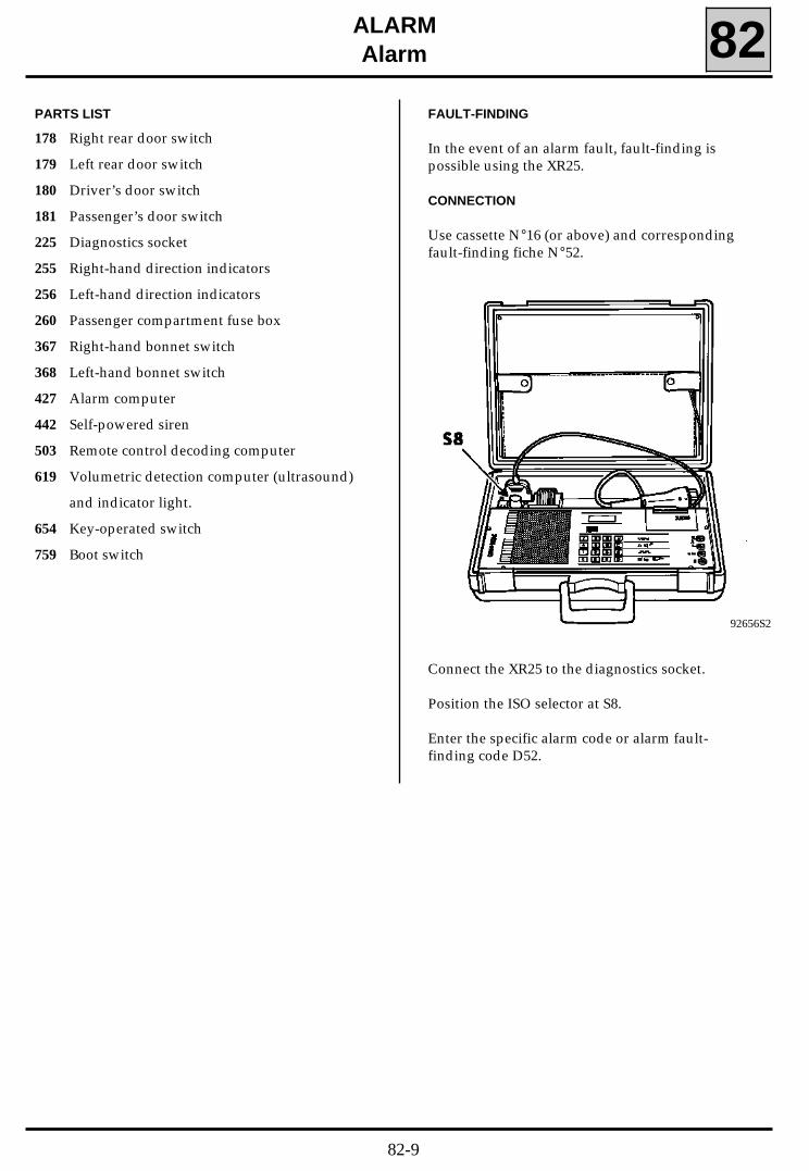
FAULT-FINDING
In the event of an alarm fault, fault-finding ispossible using the XR25.
CONNECTION
Use cassette N°16 (or above) and correspondingfault-finding fiche N°52.
92656S2
Connect the XR25 to the diagnostics socket.
Position the ISO selector at S8.
Enter the specific alarm code or alarm fault-finding code D52.
82-9

ALARMAlarm 82
FAULT-FINDING - XR25 FICHE
FI21652
82-10
c54021.0
ALARMAlarm 82
FAULT-FINDING - INTRODUCTION
PRECAUTION
For all checks carried out on the 15-way alarm computer connector, bornier Elé. 1302 must be used.
Bornier Elé. 1302 allows the continuity to be checked. To do this, simply connect the bornier to the wiring endof the 15-way alarm computer connector.
INTRUSION INDICATION
When the alarm is disarmed, if triggering of the alarm has been detected during the period for which thealarm was armed, the driver will be informed of this by 3 bleeps.
Also, the alarm indicator light will indicate the origin of the last triggering of the alarm. To do this, aftertriggering, disarm the alarm and then check the frequency of the flashing of the alarm indicator light:
- one flash of the alarm indicator light every 1.5 seconds = alarm triggered by ultrasound detection,
- two flashes of the alarm indicator light every 1.5 seconds = alarm triggered by perimetric detection,
- three flashes of the alarm indicator light every 1.5 seconds = other (alarm armed: switching on of theignition or sabotage of the siren or sabotage of the switch).
82-11

c54021.0
ALARMAlarm 82
FAULT-FINDING - INTERPRETATION OF XR25 BARGRAPHS
Right-hand bargraph 1 extinguished Fiche n° 52
XR25/Alarm computer communication1
Use bornier Elé. 1302 for any operation at on the 15-way alarm computerconnector.INSTRUCTIONS
When communication has been established, deal with any illuminated faultbargraphs.
AFTERREPAIR
Check that the XR25 is not the cause of the fault by trying to communicate with a computer on anothervehicle.Check that the ISO interface is in position S8 and that you are using the latest version of the XR25 cassetteand the correct access code (D52).Check the battery voltage (U>10.5V). Charge the battery if necessary.
Check that the alarm computer connectors are engaged correctly.Check that the alarm computer is correctly supplied:- earth on track 12 of the 15-way alarm computer connector- +before ignition on track 5 of the black 5-way alarm computer connector.
Check that the diagnostics socket is correctly supplied:- earth on track 5- + before ignition on track 16.
Check, and if necessary repair, the continuity and insulation of the electrical wiring between:
grey 2-way alarm 1 15 diagnostics socketcomputer connector 2 7 connector
If there is still no communication between the XR25 and the alarm computer, change the alarmcomputer.
Check the condition of the 25A "Alarm" fuse.
Change the fuse if necessary.
82-12

c54021.0
ALARMAlarm 82
FAULT-FINDING - INTERPRETATION OF XR25 BARGRAPHS
Left-hand bargraph 1 illuminated Fiche n° 52
Switch connection1
Lock and then unlock the vehicle doors. If left-hand bargraph 1 remainsilluminated, start the following fault-finding procedure.INSTRUCTIONS
Disconnect the 4-way key-operated alarm switch connector and measure the resistance between tracks 1and 3.The resistance should be:- R infinity, with the key-operated switch in the ON position- R = 0 ohm, with the key-operated switch in the OFF position.
If the resistances measured are not correct, change the key-operated alarm switch.
Lock and unlock the vehicle doors using the remote control.Enter G0** on the XR25.Refer to the "Fault-finding - Conformity check" section.
AFTERREPAIR
Check the continuity and insulation to earth of the electrical wiring between:
black 2-way alarm 1 1 key-operated computer connector 2 3 switch connector
Is the electrical wiring in good condition?
Change the alarm computer
Repair the electrical wiring.
YES
NO
82-13

c54021.0
ALARMAlarm 82
FAULT-FINDING - INTERPRETATION OF XR25 BARGRAPHS
Left-hand bargraph 2 illuminated Fiche n° 52
Siren connection2
Lock and then unlock the vehicle doors. If left-hand bargraph 2 remainsilluminated, start the following fault-finding procedure.INSTRUCTIONS
Check that the alarm computer and siren connectors are engaged correctly and that they have notdeteriorated.
Lock and unlock the vehicle doors using the remote control.Enter G0** on the XR25.Refer to the "Fault-finding - Conformity check" section.
AFTERREPAIR
Check the continuity of the electrical wiring between:
3-way siren A 15 of the 15-way alarm computer connectorconnector B1 the vehicle earth
B2 the passenger compartment fuse board.
Repair the electrical wiring if necessary.
Change the siren.
Change the alarm computer.
With the XR25 connected, select the impulse detector function (button "G", terminal "Vin").Enter the vehicle and close the doors.Arm the alarm. Switch on the ignition and check the presence of impulses on track 15 of the 15-way alarmcomputer connector.
Are impulses present?
YES
NO
82-14

c54021.0
ALARMAlarm 82
FAULT-FINDING - INTERPRETATION OF XR25 BARGRAPHS
Left-hand bargraph 7 extinguished with the ignition on Fiche n° 52
No+ after ignition7
Only refer to the study for this bargraph after checking that there are no faultbargraphs on the XR25.INSTRUCTIONS
Check the condition of the 10A "Airbag" fuse on the passenger compartment fuse board.
Change the fuse if it has blown.
Enter G0** on the XR25.Refer to the "Fault-finding - Conformity check" section.
AFTERREPAIR
With the ignition on, check the presence of ~ 12 volts on track 14 of the 15-way alarm computerconnector.
Is ~ 12 volts present?
YES
NO
Change the alarm computer.
Repair the electrical wiring between track 14 of the 15-way alarm computerconnector and the passenger compartment fuse box.
82-15

c54021.0
ALARMAlarm 82
FAULT-FINDING - INTERPRETATION OF XR25 BARGRAPHS
Enter G0** on the XR25.Refer to the "Fault-finding - Conformity check" section.
AFTERREPAIR
Right-hand bargraph 7 extinguished Fiche n° 52
No+ accessories7
Only refer to the study for this bargraph after checking that there are no faultbargraphs on the XR25.INSTRUCTIONS
Check the condition of the 10A "Clock" fuse on the passenger compartment fuse board.
Change the fuse if it has blown.
With the ignition key in the accessories position, check the presence of ~ 12 volts on track 13 of the 15-way alarm computer connector.
Is ~ 12 volts present?
YES
NO
Change the alarm computer.
Repair the electrical wiring between track 13 of the 15-way alarm computerconnector and the passenger compartment fuse box.
82-16

c54021.0
ALARMAlarm 82
FAULT-FINDING - INTERPRETATION OF XR25 BARGRAPHS
Left-hand bargraph 8, incorrect illumination Fiche n° 52
Key-operated alarm switch8
Left-hand bargraph 8 illuminated, key-operated alarm switch in the ON position= Section 1Left-hand bargraph 8 extinguished, key-operated alarm switch in the OFF position= Section 2
INSTRUCTIONS
Enter G0** on the XR25.Refer to the "Fault-finding - Conformity check" section.
AFTERREPAIR
SECTION 1 Fault-finding: Left-hand bargraph 8 illuminated with the switch inthe ON position.
INSTRUCTIONS
Disconnect the black 2-way alarm computer connector and check that left-hand bargraph 8 isextinguished.
If left-hand bargraph 8 is not extinguished, change the alarm computer.
Disconnect the 4-way key-operated alarm switch connector and measure the resistance between tracks 1and 3 (take the measurement at the switch connecter end).The resistance should be:- R infinity, with the key-operated switch in the ON position- R = 0 ohm, with the key-operated switch in the OFF position.
Are the resistances measured correct?
YES Check the insulation of the electrical wiring between tracks 1 and 2 of the black2-way alarm computer connector.
NO Change the key-operated alarm switch,
82-17

c54021.0
ALARMAlarm 82
FAULT-FINDING - INTERPRETATION OF XR25 BARGRAPHS
CONT
8
Enter G0** on the XR25.Refer to the "Fault-finding - Conformity check" section.
AFTERREPAIR
SECTION 2 Fault-finding: Left-hand bargraph 8 extinguished with theswitch in the OFF position
INSTRUCTIONS
Check that the black 2-way alarm computer connector and the 4-way key-operated alarm switchconnector are engaged correctly.
Engage the connector correctly if necessary.
Disconnect the black 2-way alarm computer connector. Shunt tracks 1 and 2 of the black 2-way at thealarm computer end and check whether left-hand bargraph 8 is extinguished.
If left-hand bargraph 8 is not extinguished, change the alarm computer.
YES Check the continuity and insulation to earth of the electrical wiring between:
black 2-way alarm 1 1 4-way key-operated alarmcomputer connector 2 3 switch connector
NO Change the key-operated alarm switch,
Disconnect the 4-way key-operated alarm switch connector and measure the resistance between tracks 1and 3 (take the measurement at the switch connecter end).The resistance should be:- R infinity, with the key-operated switch in the ON position- R = 0 ohm, with the key-operated switch in the OFF position.
Are the resistances measured correct?
82-18

c54021.0
ALARMAlarm 82
FAULT-FINDING - INTERPRETATION OF XR25 BARGRAPHS
Left-hand bargraph 9, incorrect illumination Fiche n° 52
Tailgate9
Left-hand bargraph 9 illuminated, tailgate closed = Section 1Left-hand bargraph 9 extinguished, tailgate open = Section 2INSTRUCTIONS
Enter G0** on the XR25.
Refer to the "Fault-finding - Conformity check" section.
AFTERREPAIR
SECTION 1 Fault-finding: Left-hand bargraph 9 illuminated with the tailgateclosed
INSTRUCTIONS
Visually check that the tailgate switch has not deteriorated.
Disconnect the tailgate switch connector, then check whether left-hand bargraph 9 is extinguished.
Is left-hand bargraph 9 extinguished?
YES Change the tailgate switch.
NO Check the insulation to earth of the electrical wiring between track 6 of the 15-way alarm computer connector and the tailgate switch.
Is the electrical wiring in good condition?
YES : Change the alarm computer.
NO : Repair the electrical wiring.
82-19

c54021.0
ALARMAlarm 82
FAULT-FINDING - INTERPRETATION OF XR25 BARGRAPHS
Enter G0** on the XR25.Refer to the "Fault-finding - Conformity check" section.
AFTERREPAIR
CONT
9
SECTION 2 Fault-finding: Left-hand bargraph 9 extinguished with the tailgateopen
INSTRUCTIONS
Visually check that the tailgate switch has not deteriorated.
Connect track 6 of the 15-way alarm computer connector to the vehicle earth, then check whether left-hand bargraph 9 is illuminated.
If left-hand bargraph 9 is not illuminated, change the alarm computer.
YES Change the tailgate switch.
NO Repair the electrical wiring between:- track 6 of the 15-way alarm computer connector and the tailgate switchor- the tailgate switch and the vehicle earth
Shunt the 2-way tracks of the tailgate switch connector, then check whether left-hand bargraph 9 isilluminated.
Is left-hand bargraph 9 illuminated?
82-20

c54021.0
ALARMAlarm 82
FAULT-FINDING - INTERPRETATION OF XR25 BARGRAPHS
Right-hand bargraph 9, incorrect illumination Fiche n° 52
Side doors9
Right-hand bargraph 9 illuminated, side doors closed = Section 1Right-hand bargraph 9 extinguished, side doors open = Section 2INSTRUCTIONS
Enter G0** on the XR25.Refer to the "Fault-finding - Conformity check" section.
AFTERREPAIR
SECTION 1 Fault-finding: Right-hand bargraph 9 illuminated with doors closedINSTRUCTIONS
Check the insulation to earth of the electrical wiring between 15-way alarm computer connector tracks:- 4 and the right front door switch- 7 and the right rear door switch- 8 and the left rear door switch- 9 and the left front door switch.
Repair the electrical wiring if necessary.
YES Change the right rear door switch.
NO Change the alarm computer.
Close the right front, left rear and right rear doors. Disconnect the left front door connector and checkwhether right-hand bargraph 9 is extinguished.
If right-hand bargraph 9 is extinguished, change the left front door switch.
Close the left front, left rear and right rear doors. Disconnect the right front door connector and checkwhether right-hand bargraph 9 is extinguished.
If right-hand bargraph 9 is extinguished, change the right front door switch.
Close the right front, left front and right rear doors. Disconnect the left rear door connector and checkwhether right-hand bargraph 9 is extinguished.
If right-hand bargraph 9 is extinguished, change the left rear door switch.
Close the right front, left front and left rear doors. Disconnect the right rear door connector and checkwhether right-hand bargraph 9 is extinguished.
Is right-hand bargraph 9 extinguished?
82-21

c54021.0
ALARMAlarm 82
FAULT-FINDING - INTERPRETATION OF XR25 BARGRAPHS
Enter G0** on the XR25.Refer to the "Fault-finding - Conformity check" section.
AFTERREPAIR
Carry out the following tests to determine which door is implicated.Close all four doors (right-hand bargraph 9 should be extinguished).Open the left front door and check whether right-hand bargraph 9 is illuminated.
If right-hand bargraph 9 is not illuminated, consult the study right-hand bargraph 9 CONT 2.
CONT 1
9
SECTION 2 Fault-finding: right-hand bargraph 9 extinguished with side doorsopen
INSTRUCTIONS
Close all four doors (right-hand bargraph 9 should be extinguished).Open the right front door and check whether right-hand bargraph 9 is illuminated.
If right-hand bargraph 9 is not illuminated, consult the study right-hand bargraph 9 CONT 3.
Close all four doors (right-hand bargraph 9 should be extinguished).Open the left rear door and check whether right-hand bargraph 9 is illuminated.
If right-hand bargraph 9 is not illuminated, consult the study right-hand bargraph 9 CONT 4.
Close all four doors (right-hand bargraph 9 should be extinguished).Open the right rear door and check whether right-hand bargraph 9 is illuminated.
Is right-hand bargraph 9 illuminated?
YES
NO
Consult the study right-hand bargraph 9 CONT 5.
Change the alarm computer.
82-22

c54021.0
ALARMAlarm 82
FAULT-FINDING - INTERPRETATION OF XR25 BARGRAPHS
Enter G0** on the XR25.
Refer to the "Fault-finding - Conformity check" section.
AFTERREPAIR
Visually check that the left front door switch has not deteriorated.
CONT 2
9
Shunt the 2-way tracks of the left front door switch connector and check whether right-hand bargraph 9is illuminated.
Is right-hand bargraph 9 illuminated?
YES
NO
Change the left front door switch.
Repair the electrical wiring between:- track 9 of the 15-way alarm computer connector and the left front door
switch,- the left front door switch and the vehicle earth.
Connect track 9 of the 15-way alarm computer connector to the vehicle earth and check whether right-hand bargraph 9 is illuminated.
If right-hand bargraph 9 is not illuminated, change the alarm computer.
82-23

c54021.0
ALARMAlarm 82
FAULT-FINDING - INTERPRETATION OF XR25 BARGRAPHS
Enter G0** on the XR25.Refer to the "Fault-finding - Conformity check" section.
AFTERREPAIR
Visually check that the right front door switch has not deteriorated.
CONT 3
9
Shunt the 2-way tracks of the right front door switch connector and check whether right-hand bargraph9 is illuminated.
Is right-hand bargraph 9 illuminated?
YES
NO
Change the right front door switch.
Repair the electrical wiring between:- track 4 of the 15-way alarm computer connector and the right front door
switch,- the right front door switch and the vehicle earth.
Connect track 4 of the 15-way alarm computer connector to the vehicle earth and check whether right-hand bargraph 9 is illuminated.
If right-hand bargraph 9 is not illuminated, change the alarm computer.
82-24

c54021.0
ALARMAlarm 82
FAULT-FINDING - INTERPRETATION OF XR25 BARGRAPHS
Enter G0** on the XR25.Refer to the "Fault-finding - Conformity check" section.
AFTERREPAIR
Visually check that the left rear door switch has not deteriorated.
CONT 4
9
Shunt the 2-way tracks of the left rear door switch connector and check whether right-hand bargraph 9 isilluminated.
Is right-hand bargraph 9 illuminated?
YES
NO
Change the left rear door switch.
Repair the electrical wiring between:- track 8 of the 15-way alarm computer connector and the left rear door switch,- the left rear door switch and the vehicle earth.
Connect track 8 of the 15-way alarm computer connector to the vehicle earth and check whether right-hand bargraph 9 is illuminated.
If right-hand bargraph 9 is not illuminated, change the alarm computer.
82-25

c54021.0
ALARMAlarm 82
FAULT-FINDING - INTERPRETATION OF XR25 BARGRAPHS
Enter G0** on the XR25.
Refer to the "Fault-finding - Conformity check" section.
AFTERREPAIR
Visually check that the right rear door switch has not deteriorated.
CONT 5
9
Shunt the 2-way tracks of the right rear door switch connector and check whether right-hand bargraph 9is illuminated.
Is right-hand bargraph 9 illuminated?
YES
NO
Change the right rear door switch.
Repair the electrical wiring between:- track 7 of the 15-way alarm computer connector and the right rear door
switch,- the right rear door switch and the vehicle earth.
Connect track 7 of the 15-way alarm computer connector to the vehicle earth and check whether right-hand bargraph 9 is illuminated.
If right-hand bargraph 9 is not illuminated, change the alarm computer.
82-26

c54021.0
ALARMAlarm 82
FAULT-FINDING - INTERPRETATION OF XR25 BARGRAPHS
Left-hand bargraph 10, incorrect illumination Fiche n° 52
Bonnet10
Left-hand bargraph 10 illuminated, bonnet closed = Section 1Left-hand bargraph 10 extinguished, bonnet open = Section 2INSTRUCTIONS
Enter G0** on the XR25.Refer to the "Fault-finding - Conformity check" section.
AFTERREPAIR
SECTION 1 Fault-finding: Left-hand bargraph 10 illuminated with the bonnetclosed
INSTRUCTIONS
Visually check that the two bonnet switches have not deteriorated.
YES Change the right-hand bonnet switch.
NO Check the insulation to earth of the electrical wiring between track 5 of the 15-wat alarm computer connector and the left and right-hand bonnet switchconnectors.
Is the electrical wiring in good condition?
Disconnect the left-hand bonnet switch connector and check whether left-hand bargraph 10 isextinguished.
If left-hand bargraph 10 is extinguished, change the left-hand bonnet switch.
Disconnect the right-hand bonnet switch connector and check whether left-hand bargraph 10 isextinguished.
Is left-hand bargraph 10 extinguished?
YES : Change the alarm computer.
NO : Repair the electrical wiring.
82-27

c54021.0
ALARMAlarm 82
FAULT-FINDING - INTERPRETATION OF XR25 BARGRAPHS
Enter G0** on the XR25.Refer to the "Fault-finding - Conformity check" section.
AFTERREPAIR
Visually check that the two bonnet switches have not deteriorated.
CONT
10
SECTION 2 Fault-finding: Left-hand bargraph 10 extinguished with bonnetopen
INSTRUCTIONS
Connect track 5 of the 15-way alarm computer connector to the vehicle earth and check whether left-hand bargraph 10 is illuminated.
If left-hand bargraph 10 is not illuminated, change the alarm computer.
Shunt the 2-way tracks of the left bonnet switch connector and check whether left-hand bargraph 10 isilluminated.
If left-hand bargraph 10 is illuminated, change the left bonnet switch.
Shunt the 2-way tracks of the right bonnet switch connector and check whether left-hand bargraph 10 isilluminated.
Is left-hand bargraph 10 illuminated?
YES
NO
Change the right bonnet switch.
Repair the electrical wiring between the right and left bonnet switches and:- track 5 of the 15-way alarm computer connector,- the vehicle earth.
82-28

c54021.0
ALARMAlarm 82
Do not refer to these customer complaints until a complete XR25 check has beencarried out.
INSTRUCTIONS
Order ofoperations
Function to be checked Action BargraphDisplay and
notes
1 XR25dialogue
D52(selector
at S8) n.52
2
Conformity of the alarmcomputer G70*
XXX
Part number displayed inthree sequences
3 Configuration of thesiren type
Ensure that theconfiguration of the sirentype corresponds to the
legislation in force for thecountry concerned.
14
15
FAULT-FINDING - CONFORMITY CHECK
82-29

FAULT-FINDING - CUSTOMER COMPLAINTS
c54021.0
ALARMAlarm
Do not refer to these customer complaints until a complete XR25 check has beencarried out.
INSTRUCTIONS
NO COMMUNICATION WITH THE XR25
ALARM CANNOT BE ARMED USING THE REMOTE CONTROL(the alarm indicator light remains extinguished)
ALARM CANNOT BE DISARMED USING THE REMOTE CONTROL(the alarm indicator light remains illuminated)
ALARM CANNOT BE ARMED USING THE KEY-OPERATED ALARM SWITCH
ALARM CANNOT BE DISARMED USING THE KEY-OPERATED ALARM SWITCH
LEFT AND RIGHT DIRECTION INDICATORS DO NOT FLASH WHEN THE ALARM IS ARMEDAND/OR DISARMED USING THE REMOTE CONTROL
LEFT DIRECTION INDICATORS DO NOT FLASH WHEN THE ALARM IS ARMED AND/ORDISARMED USING THE REMOTE CONTROL
RIGHT DIRECTION INDICATORS DO NOT FLASH WHEN THE ALARM IS ARMED AND/ORDISARMED USING THE REMOTE CONTROL
DIRECTION INDICATORS DO NOT FLASH WHEN THE ALARM IS TRIGGERED
UNWANTED TRIGGERING OF THE SIREN(with no illumination of the direction indicators)
UNWANTED TRIGGERING OF THE ALARM WHILE ARMED(with illumination of the direction indicators)
NO VOLUMETRIC DETECTION WITH THE ALARM ARMED
NO PERIMETRIC DETECTION WITH THE ALARM ARMED(no bleep and no flashing of the direction indicators when the alarm is armed using the remotecontrol)
CHART 1
CHART 2
CHART 3
CHART 4
CHART 5
CHART 6
CHART 7
CHART 8
CHART 9
CHART 10
CHART 11
CHART 12
CHART 13
82
82-30

FAULT-FINDING CHARTS
c54021.0
ALARMAlarm 82
CHART 1 NO COMMUNICATION WITH THE XR25
Use bornier Elé. 1302 for any work on the 15-way alarm computer connector.INSTRUCTIONS
Check the condition of the 25A "Alarm" fuse.Change the fuse if necessary.
Check that the XR25 is not the cause of the fault by trying tocommunicate with a computer on another vehicle.Check that the ISO interface is in position S8 and that you are usingthe latest version of the XR25 cassette and the correct access code(D52).Check the voltage of the battery (U>10.5 volts). Recharge the batteryif necessary.
When communication is established, deal with any illuminated fault bargraphs.AFTER
REPAIR
Check that the alarm computer connectors are engaged correctly.Check that the alarm computer supply is correct:
- earth on track 12 of the 15-way alarm computer connector,- +before ignition on track 5 of the black 5-way alarm computer
connector.
Check that the diagnostics socket supply is correct:- earth on track 5,- + before ignition on track 16.Check and if necessary repair the continuity and insulation of theelectrical wiring between:
grey 2-way alarm 1 15 diagnostics socketcomputer connector 2 7 connector
If there is no dialogue between the XR25 and the alarm computer,change the alarm computer.
82-31

FAULT-FINDING CHARTS
c54021.0
ALARMAlarm 82
CHART 2 THE ALARM CANNOT BE ARMED USING THE REMOTE CONTROL(the alarm indicator light remains extinguished)
Do not refer to the study for this status bargraph until the absence of faultbargraphs and the correct illumination of the status bargraphs on the XR25 hasbeen checked.
INSTRUCTIONS
no Refer to the "Engine Immobiliser RemoteControl"fault-finding procedure.
yes
Is it possible to lock the vehicle doors usingthe remote control?
Check the position of the key-operated switch(located under the passenger airbag).
Is the key-operated switch in the ON position?
Check that the alarm is operating correctly by locking the vehicle doors using theremote control.
AFTER
REPAIR
yes
no
no
Refer to Chart 3.
yes
End of fault-finding.
Turn the key-operated switch to the ONposition then lock the vehicle doors using the
remote control.Is it possible to arm the alarm?
no Change the fuse.
yes
Check that the alarm computer connectorsare engaged correctly.
Are the connectors engaged correctly?no Engage the alarm computer
connectors correctly.
Check the condition of the 25 A "Alarm" fuse.
Is the fuse in good condition?
yes
A
82-32

FAULT-FINDING CHARTS
c54021.0
ALARMAlarm 82
Check that the alarm is operating correctly by locking the vehicle doors using theremote control.
AFTER
REPAIR
no
CHART 2CONT
A
Repair the electrical wiring between the"Alarm" fuse on the passenger compartment
fuse board and track 5 of the 5-way alarmcomputer connector.
yes
no Repair the faulty electrical wiring
Check the presence of ~ 12 volts + beforeignition on track 5 of the 5-way alarm
computer connector.Is ~ 12 volts present?
yes
noChange the remote control decoding
computer.
yes
Change the alarm computer.
Connect the XR25 and select the impulsedetection function (button "G", terminal"Vin"). Check that there is an impulse on
track B5 of the 18-way remote controldecoding computer connector by locking the
vehicle doors using the remote control.Is there an impulse?
Check the condition of the electrical wiringbetween:
- track 10 of the 15-way alarm computerconnector and track B5 of the 18-wayremote control decoding computerconnector
- track 12 of the 15-way alarm computerconnector and the vehicle earth.Is the electrical wiring in good condition?
82-33

FAULT-FINDING CHARTS
c54021.0
ALARMAlarm 82
CHART 3 THE ALARM CANNOT BE DISARMED USING THE REMOTE CONTROL(the alarm indicator light remains illuminated)
Do not refer to the study for this status bargraph until the absence of faultbargraphs and the correct illumination of the status bargraphs on the XR25 hasbeen checked.
INSTRUCTIONS
no Refer to the "Engine Immobiliser RemoteControl"fault-finding procedure.
yes
Is it possible to lock the vehicle doors usingthe remote control?
Check that the alarm is operating correctly by locking the vehicle doors using theremote control.
AFTER
REPAIR
no Repair the electrical wiring.
yes
no Change the remote control decodingcomputer.
Check the condition of the electrical wiringbetween track 11 of the 15-way alarm
computer connector and track B4 of the 18-way remote control decoding computer
connector. Is the electrical wiring in goodcondition?
yes
Change the alarm computer.
Enter the vehicle by opening one of the frontdoors using the key.
Connect the XR25 and select the impulsedetection function (button "G", terminal"Vin"). Check that there is an impulse on
track B4 of the 18-way remote controldecoding computer connector when the
vehicle doors are unlocked using the remotecontrol.
Is there an impulse?
82-34

FAULT-FINDING CHARTS
c54021.0
ALARMAlarm 82
CHART 4 THE ALARM CANNOT BE ARMED USING THEKEY-OPERATED ALARM SWITCH
Do not refer to the study for this status bargraph until the absence of faultbargraphs and the correct illumination of the status bargraphs on the XR25 hasbeen checked.
INSTRUCTIONS
no Change the alarm computer.
yes
Disconnect the black 2-way alarm computerconnector. Lock the vehicle doors
using the remote control and check whether the alarm is armed.
Is the alarm armed?
Place the key-operated alarm switch in the ON position and check that the alarm isarmed (the alarm indicator light is illuminated ~ 30 seconds then flashes) whenthe vehicle doors are locked using the remote control.
AFTER
REPAIR
no Change the key-operated alarm switch.
yes
Check the insulation of the electrical wiringbetween tracks 1 and 2 of the black 2-way
alarm computer connector.
Disconnect the 4-way key-operated alarmswitch connector and measure the resistance
between tracks 1 and 3 of this connector.The resistance should be:
- key-operated switch in the ON position, Rinfinity,
- key-operated switch in the OFF position, R= 0 ohm.
Are these the resistances measured?
82-35

FAULT-FINDING CHARTS
c54021.0
ALARMAlarm 82
CHART 5 THE ALARM CANNOT BE DISARMED USING THE KEY-OPERATEDALARM SWITCH
Do not refer to the study for this status bargraph until the absence of faultbargraphs and the correct illumination of the status bargraphs on the XR25 hasbeen checked.
INSTRUCTIONS
Place the key-operated alarm switch in the OFF position and check that the alarmremains disarmed (the alarm indicator light remains extinguished) when thevehicle doors are locked using the remote control.
AFTER
REPAIR
no Engage the connectors correctly.
yes
Check that the black 2-way alarm computerconnector and the 4-way key-operated alarm
switch connector are engaged correctly.Are the connectors engaged correctly?
no Change the alarm computer.
yes
Disconnect the black 2-way alarm computerconnector. Shunt tracks 1 and 2 of the black 2-
way alarm computer connector.Lock the vehicle doors using the remote
control and check that the alarm is disarmed.Is the alarm disarmed?
no Change the key-operated alarm switch.
yes
Check the continuity and insulation to earthof the electrical wiring between:
black 2-way 1 1 key-operatedalarm computer and switchconnector 2 3 connector
Disconnect the 4-way key-operated alarmswitch connector and measure the resistance
between tracks 1 and 3 of this connector.The resistance should be:
- key-operated switch in the ON position, Rinfinity,
- key-operated switch in the OFF position, R= 0 ohm.
Are these the resistances measured?
82-36

FAULT-FINDING CHARTS
c54021.0
ALARMAlarm 82
CHART 6 THE LEFT AND RIGHT DIRECTION INDICATORS DO NOT FLASH WHENTHE ALARM IS ARMED AND/OR DISARMED USING THE REMOTE
CONTROL
Check that all of the openings have been closed correctly before arming and/orarming the alarm using the remote control. Do not refer to the study for this statusbargraph until the absence of fault bargraphs and the correct illumination of thestatus bargraphs on the XR25 has been checked.
INSTRUCTIONS
no Change the fuse.
yes
Check the condition of the 25 A "Alarm" fuse.
Is the fuse in good condition?
Check that the direction indicators operate correctly when the alarm is armed ordisarmed.
AFTER
REPAIR
noRefer to the "Fault-finding - Interpretation of
XR25 bargraphs" section.
yes
noCheck the condition of the 10 A "Hazard
warning lights" fuse. Check the condition ofthe direction indicator bulbs.
yes
Check that the alarm computer connectorsare engaged correctly.
Are the connectors engaged correctly?no Engage the alarm computer connectors
correctly.
Switch on the hazard warning lights andcheck that all of the direction indicator bulbs
are working.Are the direction indicators working?
Connect the XR25.Use fiche n° 52 (code D 52).
Close the doors, the bonnet and the boot andcheck that left and right-hand bargraph 9
and left-hand bargraph 10 are extinguished.Are these bargraphs extinguished?
yes
A
82-37

FAULT-FINDING CHARTS
c54021.0
ALARMAlarm 82
Check that the direction indicators operate correctly when the alarm is armed ordisarmed.
AFTER
REPAIR
CHART 6CONT
A
no Repair the faulty electrical wiring.
yes
Change the alarm computer.
Check the condition of the electrical wiringbetween the 15-way alarm computer
connector and tracks:- 10 and B5 of the 18-way remote control
decoding computer connector,- 11 and B4 of the 18-way remote control
decoding computer connector.Is the electrical wiring in good condition?
82-38

FAULT-FINDING CHARTS
c54021.0
ALARMAlarm 82
Check that the left direction indicators operate correctly when the alarm is armedor disarmed.
AFTER
REPAIR
CHART 7 THE LEFT DIRECTION INDICATORS DO NOT FLASH WHEN THEALARM IS ARMED AND/OR DISARMED USING THE REMOTE
CONTROL
Do not refer to the study for this status bargraph until the absence of faultbargraphs and the correct illumination of the status bargraphs on the XR25 hasbeen checked.
INSTRUCTIONS
no Check the condition of the left directionindicator bulbs.
yes
Switch on the hazard warning lights andcheck that the left direction indicator bulbs
work.Do the left direction indicators work?
yes
Change the alarm computer.
Check the condition of the electrical wiring oftrack 1 of the 5-way alarm computer
connector.Is the electrical wiring in good condition?
no Repair the electrical wiring.
82-39

FAULT-FINDING CHARTS
c54021.0
ALARMAlarm 82
Check that the right direction indicators operate correctly when the alarm isarmed or disarmed.
AFTER
REPAIR
CHART 8 THE RIGHT DIRECTION INDICATORS DO NOT FLASH WHEN THEALARM IS ARMED AND/OR DISARMED USING THE REMOTE
CONTROL
Do not refer to the study for this status bargraph until the absence of faultbargraphs and the correct illumination of the status bargraphs on the XR25 hasbeen checked.
INSTRUCTIONS
no Check the condition of the right directionindicator bulbs.
yes
Switch on the hazard warning lights andcheck that the right direction indicator bulbs
work. Do the right direction indicators work?
yes
Change the alarm computer.
Check the condition of the electrical wiring oftrack 2 of the 5-way alarm computer
connector.Is the electrical wiring in good condition?
no Repair the electrical wiring.
82-40

FAULT-FINDING CHARTS
c54021.0
ALARMAlarm 82
CHART 9 THE DIRECTION INDICATORS DO NOT FLASH WHEN THE ALARM ISTRIGGERED
Check that the direction indicators operate correctly when the alarm is armed ordisarmed.
AFTER
REPAIR
Check that all of the openings have been closed correctly before arming and/orarming the alarm using the remote control. Do not refer to the study for this statusbargraph until the absence of fault bargraphs and the correct illumination of thestatus bargraphs on the XR25 has been checked.
INSTRUCTIONS
no Refer to the "Fault-finding - Interpretation ofXR25 bargraphs" section.
yes
no Change the faulty bulb.
Connect the XR25.Use fiche n° 52 (code D 52).
Close the doors, the bonnet and the boot andcheck that left and right-hand bargraph 9
and left-hand bargraph 10 are extinguished.Are these bargraphs extinguished?
yes
no Repair the faulty electrical wiring.
Switch on the hazard warning lights andcheck that all of the direction indicator bulbs
are working.Are the direction indicators working?
yes
Change the alarm computer.
Check the condition of the electrical wiring oftracks 1 and 2 of the 5-way alarm computer
connector.Is the electrical wiring in good condition?
82-41

FAULT-FINDING CHARTS
c54021.0
ALARMAlarm 82
CHART 10 UNWANTED TRIGGERING OF THE SIREN(with no illumination of the direction indicators)
Do not refer to the study for this status bargraph until the absence of faultbargraphs and the correct illumination of the status bargraphs on the XR25 hasbeen checked.
instruction
yes Change the siren.
no
Check that the siren operates normally.AFTER
REPAIR
Measure the length of time for which thesiren sounds each time it is triggered.
Does the siren sound for more than 30seconds each time it is triggered?
no Engage the alarm computer connectorscorrectly.
yes
no Change the alarm computer.
Check that the alarm computer connectorsare engaged correctly.
Are the connectors engaged correctly?
yes
no Repair the electrical wiring.
yes
Change the siren.
Check the continuity of the electrical wiringbetween the 3-way siren connector, tracks
- A and 15 of the 15-way alarm computerconnector,
- B1 and the vehicle earth,- B2 and the passenger compartment fuse
board.Is the electrical wiring in good condition?
Connect the XR25 and select the impulsedetection function (button "G", terminal
"Vin"). Enter the vehicle and close the doors.Arm the alarm and check that there are
impulses on track 15 of the 15-way alarmcomputer connector.Are there impulses ?
82-42

yesno
FAULT-FINDING CHARTS
c54021.0
ALARMAlarm 82
CHART 11 UNWANTED TRIGGERED OF THE ALARM WHEN ARMED(with illumination of the direction indicators)
Important: The command GO** (erasing of the memory) must NOT be used beforethis fault-finding procedure has been carried out. Note: The origin of the latest unwanted triggering of the alarm is displayed by thealarm indicator light (refer to the "Fault-finding - Introduction" section.
INSTRUCTIONS
yesOn the XR25,
enter G03* and read the display.
Is it ?
no
Check the origin of triggering of the alarm.Connect the XR25. Use fiche n° 52
and check whether left-hand bargraph 3 isilluminated.
Is left-hand bargraph 3 illuminated?
Enter G0** on the XR25.Refer to the "Fault-finding - Conformity check" section.
AFTER
REPAIR
X1 -
1 ≤ X ≤ 4
C
yesno
yesOn the XR25,
enter G04* and read the display.
Is it ?X1 -
1 ≤ X ≤ 4
Refer to the study for left-hand status bargraph 10.
yesno
yesOn the XR25,
enter G05* and read the display.
Is it ?X1 -
1 ≤ X ≤ 4
no
no
On fiche n° 52, check whether left-handbargraph 4 is illuminated.
Is left-hand bargraph 4 illuminated?
On fiche n° 52, check whether left-handbargraph 5 is illuminated.
Is left-hand bargraph 5 illuminated?
A
D
82-43

FAULT-FINDING CHARTS
c54021.0
ALARMAlarm 82
AFTER
REPAIR
CHART 11CONT 1
yesno
yesOn the XR25,
enter G23* and read the display.
Is it ?X1 -
1 ≤ X ≤ 4
Refer to the study for right-hand status bargraph 9.
no
On fiche n° 52, check whether right-handbargraph 3 is illuminated. Is right-hand
bargraph 3 illuminated?
yesno
yesOn the XR25,
enter G24* and read the display.
Is it ?X1 -
1 ≤ X ≤ 4
Change the detectioncomputer.
no
On fiche n° 52, check whether right-handbargraph 4 is illuminated.
Is right-hand bargraph 4 illuminated?
B
A
Enter G0** on the XR25.Refer to the "Fault-finding - Conformity check" section.
yesno
yesOn the XR25,
enter G06* and read the display.
Is it ?X1 -
1 ≤ X ≤ 4
Refer to the study for left-hand status bargraph 6.
no
On fiche n° 52, check whether left-handbargraph 6 is illuminated. Is left-hand
bargraph 6 illuminated?
82-44

FAULT-FINDING CHARTS
c54021.0
ALARMAlarm 82
AFTER
REPAIR
CHART 11CONT 2
yesno
yesOn the XR25,
enter G26* and read the display.
Is it ?X1 -
1 ≤ X ≤ 4
Refer to the study for left-hand fault bargraph 1.
no
On fiche n° 52, check whether right-handbargraph 6 is illuminated.
Is right-hand bargraph 6 illuminated
Change the alarm computer.
B
Enter G0** on the XR25.Refer to the "Fault-finding - Conformity check" section.
yesno
yes On the XR25,
enter G25* and read the display.
Is it ?X1 -
1 ≤ X ≤ 4
Refer to the study for left-hand status bargraph 9.
no
On fiche n° 52, check whether right-handbargraph 5 is illuminated.
Is right-hand bargraph 5 illuminated?
82-45

FAULT-FINDING CHARTS
c54021.0
ALARMAlarm 82
AFTER
REPAIR
Enter G0** on the XR25.
Refer to the "Fault-finding - Conformity check" section.
CHART 11CONT 3
noEngage the alarm computer connectors
correctly.
C
yes
Check that the alarm computer connectorsare engaged correctly.
Are the connectors engaged correctly?
no Change the alarm computer.
yes
Change the siren.
Connect the XR25 and select the impulsedetection function ("G", terminal "Vin").
Enter the vehicle and close the doors. Arm the alarm and check that there areimpulses on track 15 of the 15-way alarm
computer connector.Are there impulses?
82-46

yes
FAULT-FINDING CHARTS
c54021.0
ALARMAlarm 82
AFTER
REPAIR
Enter G0** on the XR25.Refer to the "Fault-finding - Conformity check" section.
CHART 11CONT 4
no Repair the electrical wiring.
D
no Change the alarm computer.
yes
Change the detection computer.
Check the continuity of the electrical wiringbetween:
15-way alarm 2 B2 detectioncomputer and computerconnector 3 B3 connector
Is the electrical wiring in good condition?
Reconnect all of the connectors.Measure the voltage on track B3 of the 6-way
detection computer connector in thefollowing configuration:
- Alarm disarmed, check that the voltage is 0volts,
- Alarm armed, check that the voltage is ~12 volts.
Are these the voltages measured?
82-47

yes
FAULT-FINDING CHARTS
c54021.0
ALARMAlarm 82
CHART 12 NO VOLUMETRIC DETECTION WHEN THE ALARM IS ARMED
Check that the volumetric detection inhibiting procedure has not been carriedout.INSTRUCTIONS
no
Check the continuity of the electrical wiringbetween track 2 of the 15-way alarm
computer connector and track B2 of the 6-way detection computer connector.
yes
With the alarm armed, (on fiche n° 52, left-hand bargraph 12 illuminated), check the
status of the alarm indicator light.Is the alarm indicator light illuminated
(permanently then flashing)?
Lock yourself in the vehicle. Arm the alarm and wait until the alarm indicator lightflashes before moving to check that the siren is triggered.
AFTER
REPAIR
Check the continuity of the electrical wiringbetween:
15-way alarm 2 B2 detectioncomputer and computerconnector 3 B3 connector
Is the electrical wiring in good condition?
no Repair the electrical wiring.
no Change the alarm computer.
yes
Change the detection computer.
Reconnect all of the connectors.Measure the voltage on track B3 of the 6-way
detection computer connector in thefollowing configuration:
- Alarm disarmed, check that the voltage is 0volts,
- Alarm armed, check that the voltage is ~12 volts.
Are these the voltages measured?
82-48

FAULT-FINDING CHARTS
c54021.0
ALARMAlarm 82
CHART 13 NO PERIMETRIC DETECTION WHEN THE ALARM IS ARMED (there isno bleep and the direction indicators do not flash when the alarm is
armed using the remote control)
Check that all of the openings have been closed correctly before arming thealarming the alarm using the remote control.INSTRUCTIONS
noRefer to the study for left-hand bargraph 9 in
the "Fault-finding - Interpretation of XR25bargraphs" section.
yes
Connect the XR25. Use fiche n° 52 (code D52).With the boot closed, check that left-hand
bargraph 9 is extinguished.Is left-hand bargraph 9 extinguished?
AFTER
REPAIR
noRefer to the study for left-hand bargraph 10
in the "Fault-finding - Interpretation of XR25bargraphs" section.
yes
noRefer to the study for right-hand bargraph 9in the "Fault-finding - Interpretation of XR25
bargraphs" section.
Still on fiche n° 52, bonnet closed, check thatleft-hand bargraph 10 is extinguished.Is left-hand bargraph 10 extinguished?
yes
Change the alarm computer.
Still on fiche n° 52, close the 4 side doors andcheck that right-hand bargraph 9 is
extinguished. Is right-hand bargraph 9 extinguished?
Enter G0** on the XR25.Refer to the "Fault-finding - Conformity check" section.
82-49

INSTRUMENT PANEL
Instrument panel 83GENERAL
The new Safrane vehicles are fitted with an instru-ment panel with an electronic speedometer andodometer (total and trip distance recorder).Consequently, dismantling of the instrument pa-nels is forbidden.Depending on the specification of the vehicles,these instrument panels may or may not be fittedwith a trip computer.
Note : On vehicles fitted with automatic transmis-sion, the position of the selector lever is displayedon the odometer display unit.
SPECIAL FEATURES OF CERTAIN INDICATORLIGHTS
Red engine immobiliser indicatorlight:
- indicates that the engine immobiliseris active (ignition off),
- indicates a system fault if it illumi-nates with the engine running ondiesel vehicles,
- is used for entering the fault code.
Spare
Engine oil indicator light:- if this illuminates within 30 seconds
of the ignition being switched on,this indicates that the level of engineoil is low.
Note : the message "engine oil levellow" from the voice synthesiser hasbeen discontinued.
Spare
Pre-heating and diesel injection faultindicator light.
Note : the service indicator light no longer illu-minates with the fuel indicator light.
83-1

INSTRUMENT PANEL
Instrument panel 83NEW ALLOCATION OF TRACKS
Red connector
Track Function
1 Main beam headlights indicator light
2 Rear fog lamp indicator light
3 Earth
4 Dipped headlights indicator light
5 Front fog lamps indicator light
6 Red engine immobiliser indicator light
7 Right direction indicator indicator light
8 Left direction indicator indicator light
9 +after ignition
10 +after ignition
11 +before ignition
12 Trip computer (ADAC)
13 Display lighting
14 +side lights, display
15 +instrument panel lighting withrheostat
Track Function
16 Battery charge indicator light
17 Coolant temperature indicator light
18 Pre-heating/injection fault indicatorlight
19 Injection fault output to voicesynthesiser
20 Automatic transmission fault indicatorlight/fault to voice synthesiser
21 Oil pressure indicator light
22 Coolant temperature indicator
23 Electronic earth
24 Oil level indicator
25 Oil level indicator
26 Rev counter information
27 Fuel flow information
28 Oil temperature information
29 0 volt oil temperature
30 Oil pressure information
83-2
INSTRUMENT PANEL
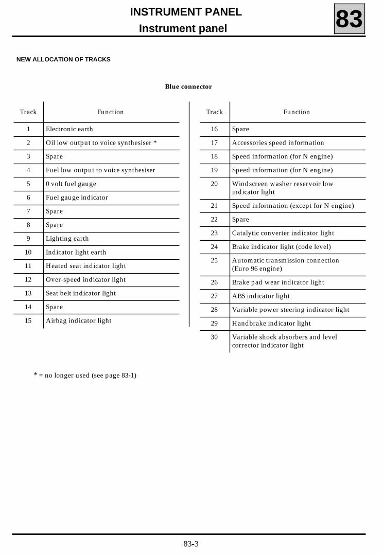
Instrument panel 83NEW ALLOCATION OF TRACKS
Blue connector
Track Function
1 Electronic earth
2 Oil low output to voice synthesiser *
3 Spare
4 Fuel low output to voice synthesiser
5 0 volt fuel gauge
6 Fuel gauge indicator
7 Spare
8 Spare
9 Lighting earth
10 Indicator light earth
11 Heated seat indicator light
12 Over-speed indicator light
13 Seat belt indicator light
14 Spare
15 Airbag indicator light
Track Function
16 Spare
17 Accessories speed information
18 Speed information (for N engine)
19 Speed information (for N engine)
20 Windscreen washer reservoir lowindicator light
21 Speed information (except for N engine)
22 Spare
23 Catalytic converter indicator light
24 Brake indicator light (code level)
25 Automatic transmission connection(Euro 96 engine)
26 Brake pad wear indicator light
27 ABS indicator light
28 Variable power steering indicator light
29 Handbrake indicator light
30 Variable shock absorbers and levelcorrector indicator light
* = no longer used (see page 83-1)
83-3

INSTRUMENT PANEL
Instrument panel 83ODOMETER (total distance recorder)
The entire range of new Safrane vehicles is fittedwith an electronic odometer (total and trip di-stance recorder)
Special features of vehicles with automatic trans-mission
On these vehicles, this new display unit will alsodisplay the position of the selector lever, the gearchange programme (normal or sport) and whe-ther or not the "winter" switch has been selected.
1 Total distance recorder
2 Trip distance recorder
3 Selector lever position (automatic
transmission)
4 Gear change programme selection (automatic
transmission)
5 Currently spare
6 "Winter" position ("snowflake" button)
(automatic transmission)
NOTE : The position of the figures on the totaldistance recorder may vary depending on the typeof gearbox fitted to the vehicle. From the firsttime that the ignition is switched on followingdisconnection of the battery, the instrumentpanel electronics identifies the type of gearboxused.
- Manual gearbox:- If the total distance recorded is less than 100,
000, the unit figure is located in the secondposition from the right. When the distancerecorded exceeds 99,999, the figures move tothe right (the unit figure is then located inthe first position on the right)
- Automatic transmission- in this case, the unit figure is always loca-
ted in the first position on the right.
83-4

INSTRUMENT PANEL
Instrument panel 83MODIFICATION TO THE OIL LEVEL INDICATOR
On these instrument panels, the engine oil levelindication is displayed for approximately 30 se-conds after the ignition is switched on after whichthe indicator displays the oil pressure.The time for which the oil level indication is dis-played no longer depends on starting the engine.
FUEL GAUGE
Vehicles fitted with this new instrument panel arealso fitted with a new fuel gauge.
WARNING: this new gauge cannot be fitted to avehicle fitted with an old instrument panel.
CONNECTION
Track Function
A Earth
B Spare
C Fuel level information
NOTE: on the entire Safrane range, the low fuellevel is now detected by the instrument panelelectronics in accordance with the resistanceindicated by the gauge.
CHECK
Indication Value in Ω (between A and C)
4/4 17 ± 2.5
3/4 57.5 ± 5
1/2 95 ± 5
1/4 177.5± 9
0 370 ± 5
NOTE: all of these values are given forinformation only. Check the variation of theresistance by moving the float.
83-5

INSTRUMENT PANEL
Instrument panel with trip computer 83SERVICE INTERVALOn petrol vehicles with a trip computer, the ser-vice interval is 15,000 km (10,000 miles). This is nolonger calculated in accordance with the engineoil temperature but simply by recording the di-stance travelled (discontinuation of the engine oiltemperature sensor)
Reminder: re-initialisation of the service interval(after carrying out a service operation) is by pres-sing the "start" button and holding it until theoperation is completed.
Note : This function is not available on right-handdrive vehicles.
The other letters remain unchanged and retainthe same functions (refer to page 83-23 ofWorkshop Repair Manual 302).
MODIFICATION TO INTEGRAL FAULT-FINDING
During the first part of integral fault-finding, theinstrument panel electronics will check the follo-wing components in addition to the functionsdescribed in Workshop Repair Manual 302 (P. 83-22):
- The fuel level indicator.Position : 0, 1/4, 1/2, 3/4, 4/4.
- The coolant temperature indicator.Position : minimum, 1/2, 3/4, 4/4, maximum.
- The illumination of the indicator lights:- low engine oil level,- low fuel level.- automatic transmission fault.
Note: the illumination of these indicator lightscauses the service indicator light to illuminate.
During the second part of integral fault-finding(odometer end), the letters "b" and "t"are notused (take no notice of whether or not they illu-minate).
83-6

INSTRUMENT PANEL
Cruise control 83
11854R
DESCRIPTION
The cruise control maintains a constant vehiclespeed without any pressure on the acceleratorbeing required.
It has no limiting action.
It is only operational at a vehicle speed ofbetween 35 ± 2 km/h (22 ± 1 m.p.h.) and 250 ± 2km/h (155 ± 1 m.p.h.). However, between 200and 250 km/h (125 and 155 m.p.h.) the systemlimits the cruising speed to 200 km/h (125 m.p.h.).
It is made up of 3 parts:
1) The cruise control computer which controlsthe system.This compares the actual vehicle speed withthe speed selected by the driverIt also analyses the condition of the variouscomponents continuously as a "fault-finding"function.
2) The pneumatic part comprises an electro-pump assembly (GEP) which supplies pneu-matic energy to the control ram.
The electropump assembly (GEP) itselfcomprises:
- a vacuum pump,
- a regulating solenoid valve,
- a venting safety solenoid valve
The control ram acts on the throttle in paral-lel with the pedal control.
The pedal follows all of the ram movementsunder its own weight. The driver can there-fore accelerate the vehicle himself at anytime if he so wishes.
3) A"control and safety" part comprises:
- The cruise control On/Off switch,
- the switches on the steering wheel, one ofwhich permits variation of the speed andone which allows deselection of the cruisecontrol or recall of the stored speed,
- the brake and clutch (manual gearbox)switches which deselect the cruise control atthe slightest pressure,
- the multifunction switch (automatictransmission) which deselects the cruisecontrol indicating the "Neutral" or "Park"position of the selector lever.
LOCATION OF COMPONENTS
• Cruise control computer (1)
This is located under the passenger seat. To gainaccess to it, move the seat forward as far aspossible and lift the carpet. Unscrew the sidefastener of the plastic cover and remove it.
The computer is retained by a bolt.
83-7

INSTRUMENT PANEL
Cruise control 83
11770-1R
• The electropump assembly (2)
This is located behind the bumper underneath thefront right-hand headlight.
Removal - Refitting
If the vehicle is fitted with headlight washers,unclip the jet covers.
Remove:
- the engine undertray,
- the front wheel arch plastic trims,
- the bumper,
- the direction indicators,
- the radiator grille,
- the metal light unit bracket after disconnectingand plugging the headlight washers pipe at theunion (it is not necessary to remove the clamp).
For further information regarding the removal ofthe components listed above, refer to the relevant"Bodywork" sections.
Disconnect the pneumatic ram air supply pipe.
Remove the two electropump assembly (GEP)metal bracket mountings.
- a nut at the front of the bracket,
- a bolt at the rear (B).
Disengage the bracket and electropump assembly(GEP) assembly.
Disconnect the 5-way (A) electropump assembly(GEP) connector and remove the assembly.
83-8

INSTRUMENT PANEL
Cruise control 83
11858R
• The control ram (3)
N7U engine
It is retained on a metal bracket by a nut, thebracket itself being secured to the cylinder headon the engine flywheel end.
G engine
It is retained on a metal bracket by a nut, thebracket itself being secured to the injection pump.
Fitting and setting the mechanical control
With the ram at rest and the throttle at idle, theremust be a safety clearance of 2 to 3 mm in order toprevent fast idle.
Secure the ram body to its bracket using the nut.
Unscrew the grooved ring (a quarter turn in thedirection of loosening).
Clip the head of the connecting rod to the throttleball joint.
Pull the grooved ring towards the body of the ramuntil the throttle spring is felt, then go back oneor two notches towards the ball joint (there is nolonger any force exerted by the spring).
Finally, tighten the two sections permanently (aquarter turn in the direction of tightening).
WARNING: When fitting a new part, the yellowfitting spacer must be removed after tighteningthe two sections.
11857R
N7Q engine
It is retained vertically on a metal bracket by a nut,the bracket itself being secured to the inletmanifold.
83-9

INSTRUMENT PANEL
Cruise control 83• The rotary switch under the steering wheel (4)
This makes the electrical connection between thesteering column and the steering wheel.
It is made up of a tape with four conductive tracks(cruise control and air bag) the length of whichpermits 2.5 revolutions of the steering wheel (fulllock plus safety excess) in each direction)
Removal - Refitting
- the cruise control connector,
- the steering wheel bolt,
- the steering wheel after positioning the wheelsstraight ahead,
- the upper half-shell by unscrewing its twomountings,
- the lower half-shell by unscrewing its threemountings.
Unscrew the three mountings (D) of the rotaryswitch under the steering wheel.
When removing the rotary switch, it is essentialto mark its position by either:
- ensuring that the wheels are in the straightahead position when it is removed in order toposition the length of tape in the centre,
- immobilising the rotary switch rotor usingadhesive tape.
NOTE : on this vehicle, when the steering wheel isremoved with the wheels in the straight aheadposition, the hub of the rotary switch locks it inorder to retain it in this position until refitting.
Disconnect the two 2-way connectors:
- the air bag connector,
- the cruise control connector.
WARNING: it is prohibited to carry out any workon the air bag or pretensioner systems near a heatsource or a naked flame; there is a risk that theymay be triggered.
IMPORTANT: when removing the steering wheel,the air bag connector (C) MUST be disconnected.The air bag is fitted with a connector which shortcircuits when it is disconnected in order to preventinadvertent triggering.
Remove:
- the air bag by its two torx screws (tighteningtorque 0.5 daN.m) located behind the steeringwheel and disconnect its connector (C),
11861R
11860R
83-10

INSTRUMENT PANEL
Cruise control 83In the event of replacement, the new part will bedelivered centred, supported by an adhesive labelwhich will tear on the first rotation of the steeringwheel (to be fitted with the wheels in the straightahead position).
Special points for refitting
Ensure that the wheels are always in the straightahead position.
Check that the rotary switch is still immobilisedbefore refitting it.
If it is not, follow the centring proceduredescribed in the "Air Bag and Seat BeltPretensioner" manual.
Change the steering wheel bolt after eachremoval (bolt pre-coated with adhesive).
Ensure the correct tightening torque is applied(4.5 daN.m).
IMPORTANT: before reconnecting the air bag, thesystem operation test procedure must be carriedout:
• check that the air bag indicator light on theinstrument panel illuminates when the ignitionis switched on.
• connect a dummy ignition module to thedriver’s air bag connector and check that theindicator light extinguishes.
• switch off the ignition, connect the air bag inplace of the dummy ignition module andsecure the air bag to the steering wheel.
• switch on the ignition, check that the indicatorlight illuminates for 3 seconds when theignition is switched on and then extinguishesand remains extinguished.
If the indicator light does not operate as describedabove, refer to the "Fault-finding" section of the"Air Bag and Seat Belt Pretensioner" manual andtest the system using the XRBAG tool (Elé 1288).
WARNING: if these instructions are not followedcorrectly the normal operation of these systemsmay be affected or they may even be inadver-tently triggered.
83-11

INSTRUMENT PANEL
Cruise control 83• The steering wheel switches (5)
Each switch has a voltage threshold which enablesthe computer to identify it.
Switch (O/R - O/R)
This has two functions:
- Cancels the cruise control if it is active. Thepreviously stored speed is retained in thememory.
- Recalls the previously stored speed and selectscruise control if it is not active.
Removal - Refitting
The air bag connector must be removed beforethese switches are removed.
For the procedure, precautions and special pointsfor refitting the air bag, refer to the previousparagraph entitled "Rotary Switch Under the
Swit ( )/
It has three functions:
- Stores a cruising speed if the switch is pressed(on one side or the other) for less than 0.5seconds,
- Increases the speed by pressing briefly severaltimes or continuously on the the left-hand sideof switch. When the button is released, the
new speed is stored.
- Reduces the speed by pressing the brieflyseveral times or continuously on switch .When the button is released, the new speed is
11862S
11861S
83-12

INSTRUMENT PANEL
Cruise control 83• The On/Off switch (6)
This is on the left-hand side of the centre console.
The "Cruise Control" indicator light is integralwith the switch.
NOTE : if this switch is used to switch off the cruisecontrol, the speed is no longer stored in the me-mory.
11863S
83-13

INSTRUMENT PANEL
Cruise control 83OPERATION
With the ignition on, the + after ignition suppliesthe cruise control On/Off switch.
When contact has been established by the On/Offswitch, + after ignition supplies track 11 of thecruise control computer and the brake and clutchswitches.
The brake and clutch switches are connected inseries and supply track 3 of the computer toconfirm their "inactive" status.
The cruise control computer takes into accounttwo parameters:
1) The actual vehicle speed supplied by the speedsensor.
2) The speed selected by the driver, entered viatracks 5 and 6 of the computer.
These two parameters are continuously comparedwith each other by the computer enabling thecomputer to control either the vacuum pump byearthing it or the cruise control solenoid valve bydisconnecting it from its earth. This alters thevacuum at the pneumatic ram. The ram maintainsa constant vehicle speed by operating thethrottle.
NOTE : the safety solenoid valve vents the circuitwhen it is disconnected from earth.
Setting the cruising speed
After operating the cruise control On/Off switch,with the vehicle travelling at a constant speed[greater than 35 km/h (20 m.p.h.)], press switch
/ on the steering wheel.
The cruising speed is stored and the driver maytake his foot off the accelerator pedal.
Now, pressing the left-hand switch:
- on the side, increases the cruising speed,
- on the side, reduces the cruising speed.
It is also possible to accelerate using the accelera-tor pedal and press the switch when thedesired speed is reached in order to store it.
NOTE: it is still possible to exceed the speed storedby pressing accelerator pedal. When the pedal isreleased, the vehicle will return to the set cruisingspeed.
Safety
Safety is ensured by:
- Two brake switches and one clutch switch(manual gearbox only).When the brake pedal or the clutch pedal ispressed, the cruise control computer safetycircuit positive supply (track 3) is interrupted.In parallel, the other brake switch sendspositive information to track 7 of the cruisecontrol computer. The earth to which thesafety solenoid was connected via the brakelights is therefore disconnected; the pneumaticcircuit is then vented. The vehicle speed is nolonger controlled.
NOTE: the safety solenoid valve may also ventthe circuit if it loses its earth following a brakelight fault.
83-14

INSTRUMENT PANEL
Cruise control 83- The multifunction switch via the automatic
transmission computer.This informs the computer of the gear selectorlever position ("Neutral" or "Park").
- The right-hand switch (O/R - O/R) on thesteering wheel.This permits the cruise control to beinterrupted voluntarily if the function is active.The computer cuts of the supply to theelectropump assembly (GEP) on track 1 and thevarious earths (the earth on track 12 of thecruise control solenoid valve and the earth ontrack 9 of the pump).
The computer also deselects the cruise control inthe following circumstances:
- When it detects acceleration (or deceleration)of the vehicle greater than 4 m/s2.WARNING: do not test the "Cruise control"function by raising the wheels.The acceleration will be greater than 4 m/s2
and the system will be deselected immediately.
- When the vehicle speed falls to below 75 % ofthe stored speed while the cruise control isactive.
- When it detects a speed below the minimumspeed required for the system to be active (e.g.:disappearance of the "Vehicle speed"information).
- When neither of the brake lights are present(or they are both faulty). Track 7 of thecomputer is no longer earthed via the brakelights.
- When a fault occurs which affects the electricalor pneumatic actuators or the electricalconnections.
However, the cruising speed remains stored in allthese safety modes. To recall it, press the right-
83-15

INSTRUMENT PANEL
Cruise control 83COMPUTER CONNECTION
11859S
Track Function
1
2
3
4
5
6
7
8
9
10
11
12
13
14
Electropump supply GEP
Gear selected by multifunction switch
Clutch- brake safety
Spare
Cruise control programming controlreturn
Cruise control programming control
Brake input via brake lights
Fault-finding information L
Acceleration control
Electronic earth
Cruise control supply
Deceleration control
Speed information
Fault-finding information K
WIRING DIAGRAM
Parts list
119 Automatic transmission computer
160 Brake switch
172 Right rear light
173 Left rear light
232 Starter relay
225 Diagnostics socket
247 Instrument panel
260 Fuse box
277 Filament failure unit
331 Cruise control switches
344 Cruise control pneumatic pump
345 Cruise control safety solenoid valve
346 Cruise control pump solenoid valve
373 Cruise control computer
485 Multifunction switch
530 Cruise control brake switch
531 Cruise control clutch switch
627 Cruise control On/Off
83-16

INSTRUMENT PANEL
Cruise control 83Wiring diagram
PRN8300
83-17

INSTRUMENT PANEL
Cruise control 83FAULT-FINDING
Some system operation faults can be found usingthe XR25.
CONNECTION
Use cassette n° 16 and the corresponding fault-finding fiche n° 58.
92656S2
Position the ISO selector at S8 and enter:
Connect the XR25 to the diagnostics socket in thepassenger compartment centre console.
11534S
D 5 8
The central display will show:
. u thent 2. u t
COMPUTER IDENTIFICATION
The cruise control computer is not identified byreading a fault code, but by direct reading of thecomputer part number after establishing dialoguebetween the computer and the XR25.
Enter:
and read the part number on the central displayof the XR25:
G 7 0 *
7 7 0 0
X X X
X X X
The number appears in three sequences. Eachsequence remains displayed for approximately 2seconds.
The display is repeated twice.
1 1
83-18

INSTRUMENT PANEL
Cruise control 83ERASING THE MEMORY
When work has been carried out on the system,the computer memory can be cleared using thecode:
(erasing faults stored in fault-finding mode
with the selector in position S8, enter:
).
This will not erase the memory of otherequipment on the vehicle.
G 0 * *
D 5 8
G 0 * *
83-19

l54021.0
INSTRUMENT PANELCruise control 83
FAULT-FINDING - XR 25 FICHE
FI21658
83-20

l54021.0
INSTRUMENT PANEL
Cruise control 83
REPRESENTATION OF BARGRAPHS
FAULTS (always on a coloured background)
If illuminated, this indicates that a fault has been found on the unit concerned. The associatedtext describes the fault.
STATUS (always on a white background)
Illuminates when dialogue is established with the computer, if it does not illuminate:- the code does not exist,- there is a fault on the XR25, on the computer or there is a line fault.
With the engine stopped, ignition on, with no action by the operator
The status bargraphs on the fiche are represented in the status they should be in with the engine stopped,ignition on with no action by the operator
- If on the fiche, the bargraph is represented the XR25 should display
- If on the fiche the bargraph is represented the XR25 should display
- If on the fiche the bargraph is represented the XR25 should display
either or
Engine running
Extinguished when the function or the status specified on the fiche is no longer carried out.
Illuminated when the function or the status specified on the fiche is carried out.
FAULT-FINDING - XR 25 FICHE
83-21
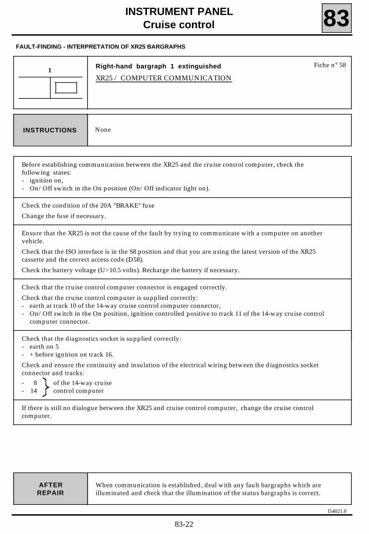
l54021.0
INSTRUMENT PANELCruise control 83
When communication is established, deal with any fault bargraphs which areilluminated and check that the illumination of the status bargraphs is correct.
AFTERREPAIR
Right-hand bargraph 1 extinguished
XR25 / COMPUTER COMMUNICATION
1
NoneINSTRUCTIONS
Fiche n° 58
FAULT-FINDING - INTERPRETATION OF XR25 BARGRAPHS
Before establishing communication between the XR25 and the cruise control computer, check thefollowing states:- ignition on,- On/Off switch in the On position (On/Off indicator light on).
Check the condition of the 20A "BRAKE" fuse
Change the fuse if necessary.
Ensure that the XR25 is not the cause of the fault by trying to communicate with a computer on anothervehicle.
Check that the ISO interface is in the S8 position and that you are using the latest version of the XR25cassette and the correct access code (D58).
Check the battery voltage (U>10.5 volts). Recharge the battery if necessary.
Check that the cruise control computer connector is engaged correctly.
Check that the cruise control computer is supplied correctly:- earth at track 10 of the 14-way cruise control computer connector,- On/Off switch in the On position, ignition controlled positive to track 11 of the 14-way cruise control
computer connector.
Check that the diagnostics socket is supplied correctly:- earth on 5- + before ignition on track 16.
Check and ensure the continuity and insulation of the electrical wiring between the diagnostics socketconnector and tracks:- 8 of the 14-way cruise- 14 control computer
If there is still no dialogue between the XR25 and cruise control computer, change the cruise controlcomputer.
83-22

l54021.0
INSTRUMENT PANELCruise control 83
Enter GO** on the XR25.Check that the cruise control is operating correctly by carrying out a road test.AFTER
REPAIR
Left-hand bargraph 1 illuminated
CRUISE CONTROL COMPUTER FAULT1
Enter the command GO**. If left-hand bargraph 1 remains illuminated, follow thefault-finding procedure below.INSTRUCTIONS
Fiche n° 58
FAULT-FINDING - INTERPRETATION OF XR25 BARGRAPHS
Change the cruise control computer.
83-23

l54021.0
INSTRUMENT PANELCruise control 83
Enter GO** on the XR25.Check that the cruise control is operating correctly by carrying out a road test.AFTER
REPAIR
Left-hand bargraph 2 illuminated
ELECTROPUMP ASSEMBLY SUPPLY OUTPUT FAULT
CO or CC to earth or CC to 12 volts on tracks 1 / 9 / 12 of the cruise controlcomputer
2
Enter the command G0**. If the left-hand bargraph 2 remains illuminated, followthe fault-finding procedure below.INSTRUCTIONS
Fiche n° 58
FAULT-FINDING - INTERPRETATION OF XR25 BARGRAPHS
Check that the cruise control computer and electropump assembly connectors are engaged correctly.
Engage the connectors correctly if necessary.
Check the continuity and the absence of short circuits to earth and to +12V on the electrical wiringbetween track 1 of the 14-way cruise control computer connector and track 5 of the electropumpassembly connector.
Repair the electrical wiring if necessary.
With the ignition on and the On/Off switch in the On position, connect +12V to track 1 of the computerand earth track 9 of the computer, then check that the vacuum pump is operating correctly (check bylistening to the pump).
Is the vacuum pump operating?
Change the cruise control computer.YES
Change the electropump assembly.NO
83-24

l54021.0
INSTRUMENT PANEL
Cruise control 83
Enter GO** on the XR25.Check that the cruise control is operating correctly by carrying out a road test.AFTER
REPAIR
Right-hand bargraph 2 illuminated
CRUISE CONTROL SOLENOID VALVE FAULT
CC cruise control solenoid valve
2
Enter the command GO**. If right-hand bargraph 2 remains illuminated, followthe fault-finding procedure below.INSTRUCTIONS
Fiche n° 58
FAULT-FINDING - INTERPRETATION OF XR25 BARGRAPHS
Check that the cruise control computer and electropump assembly connectors are engaged correctly.
Engage the connectors correctly if necessary.
With the ignition off, disconnect the cruise control computer connector.
Using a multimeter, measure the cruise control solenoid valve resistance (take the measurement at thewiring end of the connector).The value should be R~100 ohms.If the value is R~100 ohms, change the cruise control computer.
Check the continuity and the absence of short circuits to earth and to +12V on the electrical wiringbetween :
cruise control 1 and5 electropump assemblycomputer connector 12 3 connector
Is the electrical wiring in good condition?
Change the electropump assembly.
Repair the faulty electrical wiring
YES
NO
83-25

l54021.0
INSTRUMENT PANELCruise control 83
Enter GO** on the XR25.Check that the cruise control is operating correctly by carrying out a road test.AFTER
REPAIR
Left-hand bargraph 3 illuminated
VACUUM PUMP FAULT
CC or CO
3
Enter the command GO**. If left-hand bargraph 3 remains illuminated , follow thefault-finding procedure below.INSTRUCTIONS
Fiche n° 58
FAULT-FINDING - INTERPRETATION OF XR25 BARGRAPHS
Check that the cruise control computer and electropump assembly connectors are engaged correctly.
Engage the connectors correctly if necessary.
With the ignition off, disconnect the cruise control computer connector.
Using a multimeter, measure the vacuum pump resistance (take the measurement at the wiring end ofthe connector) between tracks 9 and 1 of the connector (position the multimeter earth point at track 1 ofthe connector). The value should be 8 ohms < R < 50 ohms.
If the value is 8 ohms <R < 50, replace the cruise control computer.
Check the continuity and the absence of short circuits to earth and to + 12V on the electrical wiringbetween :
cruise control 1 and5 electropump assemblycomputer connector 9 4 connector
Is the electrical wiring in good condition?
Change the electropump assembly.
Repair the faulty electrical wiring.
YES
NO
With the ignition on and the On/Off switch in the On position, connect + 12V to track 1 of the computerand earth track 9 of the computer, then check that the vacuum pump is operating correctly (check bylistening to the pump).If the vacuum pump is operating normally, change the cruise control computer computer.
83-26

l54021.0
INSTRUMENT PANELCruise control 83
Enter GO** on the XR25.Check that when pressing a steering wheel switch, right-hand bargraph 8 remainsextinguished. Check that the cruise control is operating correctly by carrying out aroad test.
AFTERREPAIR
Right-hand bargraph 8 permanently illuminated orilluminated when pressing the steering wheel switches
STEERING WHEEL SWITCHES
8
Enter the command GO**. If right-hand bargraph 8 remains permanentlyilluminated or if it is illuminated when pressing the steering wheel switches, followthe fault-finding procedure below.
INSTRUCTIONS
Fiche n° 58
FAULT-FINDING - INTERPRETATION OF XR25 BARGRAPHS
Check the continuity and the absence of short circuits to earth and to + 12V on the electrical wiringbetween:
cruise control 5 and2 steering wheelcomputer connector 6 1 switches connector
Is the electrical wiring in good condition?
Change the cruise control computer.
Repair the electrical wiring.
YES
NO
83-27

l54021.0
INSTRUMENT PANEL
Cruise control 83
Check that: Left-hand bargraph 4 is illuminated when the clutch pedal (manualgearbox) or brake pedal are pressed.Left-hand bargraph 4 remains extinguished without pressing theclutch pedal (manual gearbox) or the brake pedal.
AFTERREPAIR
Left-hand bargraph 4, incorrect illumination
CLUTCH PRESSED (MANUAL GEARBOX) OR BRAKE PRESSED4
Left-hand bargraph 4 always illuminated= Section 1Left-hand bargraph 4 always extinguished= Section 2INSTRUCTIONS
Fiche n° 58
FAULT-FINDING - INTERPRETATION OF XR25 BARGRAPHS
Shunt tracks 3 and 11 of the 14-way cruise control computer, then check whether left-hand bargraph 4 isextinguished.
Is left-hand bargraph 4 extinguished?
Ensure that the cruise control clutch (manual gearbox) and the cruise controlbrake switches are set correctly.
YES
Check the condition of the cruise control clutch (manual gearbox) and cruisecontrol brake switches. Do not operate the clutch (manual gearbox) and brakepedals during the following operations.Disconnect the switches, then, using a multimeter, measure the resistancebetween the terminal (measurements to be taken at the connector end of theswitch):If the vehicle is fitted with a manual gearbox:- 1 and 3 of the 3-way cruise control clutch switch connector.- 1 and 3 of the 3-way cruise control brake switch connector.If the vehicle is fitted with automatic transmission:- 1 and 3 of the 3-way cruise control brake switch connector.Each resistance should be R ~ 0 ohm.Are the resistances R ~ 0 ohm ?
YES Repair the electrical wiring between track 3 of the cruise controlcomputer and track B3 of the On/Off switch via the switch(es).
NO Change the faulty switch.
Change the cruise control computer.NO
Fault-finding: Left-hand bargraph 4 always illuminated withoutpressing the clutch pedal (manual gearbox) or pressing thebrake pedal.
INSTRUCTIONSSECTION 1
83-28

l54021.0
INSTRUMENT PANELCruise control 83
CONT
4
FAULT-FINDING - INTERPRETATION OF XR25 BARGRAPHS
Fault-finding: left-hand bargraph 4 remains extinguished evenwhen the clutch (manual gearbox) or the brake pedal arepressed.
INSTRUCTIONSSECTION 2
Unclip the wire from track 3 of the 14-way cruise control computer connector, then check whether left-hand bargraph 4 is illuminated.
Is left-hand bargraph 4 illuminated?
YES Check the condition of the cruise control clutch (manual gearbox) and cruisecontrol brake switches. Disconnect the switches, then, using a multimeter, measure the resistancebetween the tracks (measurements to be taken at the connector end of theswitch):If the vehicle is fitted with a manual gearbox:- 1 and 3 of the 3 -way cruise control clutch switch connector, pressing the clutchpedal.- 1 and 3 of the 3-way cruise control brake switch, pressing the brake pedal.If the vehicle is fitted with automatic transmission:- 1 and 3 of the 3-way cruise control brake switch connector, pressing the brake
pedal.Each resistance should be R infinity.Are the resistances R infinity?
YES Repair the electrical wiring between track 3 of the cruise controlcomputer and track B3 of the On/Off switch via the switch(es).
NO Change the faulty switch(es).
Change the cruise control computer.NO
Check that: Left-hand bargraph 4 is illuminated when the clutch pedal (manualgearbox) or brake pedal are pressed.Left-hand bargraph 4 remains extinguished without pressing theclutch pedal (manual gearbox) or the brake pedal.
AFTERREPAIR
83-29

l54021.0
INSTRUMENT PANELCruise control 83
Check that:- left-hand bargraph 6 is illuminated with the selector in P or N- left-hand bargraph 6 remains extinguished with the selector in D, R, 1, 2, 3.
AFTERREPAIR
Left-hand bargraph 6, incorrect illumination
AUTOMATIC TRANSMISSION SELECTOR IN P OR N6
Only refer to the study for this bargraph when the absence of fault bargraphs andthe correct illumination of the status bargraphs on the XR25 has been confirmed.INSTRUCTIONS
Fiche n° 58
FAULT-FINDING - INTERPRETATION OF XR25 BARGRAPHS
Disconnect the 14-way computer connector.
With the ignition off, using a multimeter, measure the line resistance between track 2 of this connectorand the vehicle earth:- with the selector in P or N, the measurement should read R < 10 ohms- with the selector in D, R, 1, 2, 3, the measurement should read R infinity.
Are these the resistances measured?
Change the computer.
There is a short circuit to earth on the electrical wiring between track 2 of the 14-way computer connector and the vehicle earth.Repair the electrical wiring.
YES
NO
83-30

l54021.0
INSTRUMENT PANELCruise control 83
Check that:- left-hand bargraph 8 is illuminated when switch( ) is pressed.- left-hand bargraph 8 remains extinguished when switch ( )is released.
AFTERREPAIR
Left-hand bargraph 8, incorrect illumination
ACCELERATION SWITCH ( )
8
Only refer to the study for this bargraph when the absence of fault bargraphs andthe correct illumination of the status bargraphs on the XR25 has been confirmed.INSTRUCTIONS
Fiche n° 58
FAULT-FINDING - INTERPRETATION OF XR25 BARGRAPHS
With the ( ) switch pressed, check whether right-hand bargraph 8 is illuminated.
If right-hand bargraph 8 is illuminated, refer to the right-hand bargraph 8 study.
Disconnect the 14-way cruise control computer connector.
With the ignition off, using a multimeter, measure the resistance between tracks 5 and 6 of thisconnector (take the measurement at the wiring end of the connector).- with switch ( ) released, check the presence of resistance R infinity,- with switch ( ) pressed, check the presence of resistance R ~ 260 ± 10 ohms.
Are these the resistances measured?
Change the cruise control computer.
Change the steering wheel switches.
YES
NO
83-31
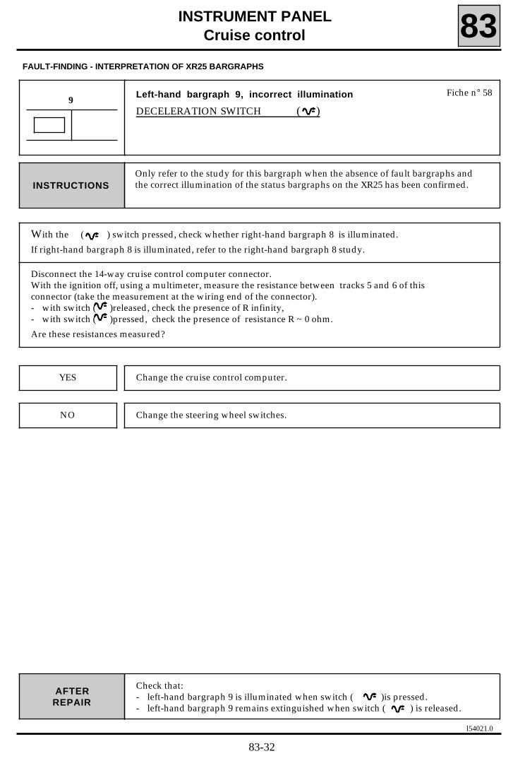
l54021.0
INSTRUMENT PANELCruise control 83
FAULT-FINDING - INTERPRETATION OF XR25 BARGRAPHS
Check that:- left-hand bargraph 9 is illuminated when switch ( )is pressed.- left-hand bargraph 9 remains extinguished when switch ( ) is released.
AFTERREPAIR
Left-hand bargraph 9, incorrect illumination
DECELERATION SWITCH ( )
9
Only refer to the study for this bargraph when the absence of fault bargraphs andthe correct illumination of the status bargraphs on the XR25 has been confirmed.INSTRUCTIONS
Fiche n° 58
With the ( ) switch pressed, check whether right-hand bargraph 8 is illuminated.
If right-hand bargraph 8 is illuminated, refer to the right-hand bargraph 8 study.
Disconnect the 14-way cruise control computer connector.With the ignition off, using a multimeter, measure the resistance between tracks 5 and 6 of thisconnector (take the measurement at the wiring end of the connector).- with switch ( )released, check the presence of R infinity,- with switch ( )pressed, check the presence of resistance R ~ 0 ohm.
Are these resistances measured?
Change the cruise control computer.
Change the steering wheel switches.
YES
NO
83-32

l54021.0
INSTRUMENT PANELCruise control 83
FAULT-FINDING - INTERPRETATION OF XR25 BARGRAPHS
Check that:- left-hand bargraph 10 is illuminated when switch (O/R - O/R) is pressed.- left-hand bargraph 10 remains extinguished when switch (O/R - O/R) is
released.
AFTERREPAIR
Left-hand bargraph 10, incorrect illumination
O/RESUME BUTTON (0/R - O/R)
10
Only refer to the study for this bargraph when the absence of fault bargraphs andthe correct illumination of the status bargraphs on the XR25 has been confirmed.INSTRUCTIONS
Fiche n° 58
With switch (O/R - O/R) pressed, check whether right-hand bargraph 8 is illuminated.
If right-hand bargraph 8 is illuminated, refer to the right-hand bargraph 8 study.
Disconnect the 14-way cruise control computer connector.With the ignition off, using a multimeter, measure the resistance between tracks 5 and 6 of thisconnector (take the measurement at the wiring end of the connector).- with switch (O/R - O/R) released, check the presence of resistance R infinity,- with switch (O/R - O/R) pressed, check the presence of resistance R ~ 909 ± 10 ohms.
Are these the resistances measured?
Change the cruise control computer.
Change the steering wheel switches.
YES
NO
83-33

l54021.0
INSTRUMENT PANEL
Cruise control 83
Check that the cruise control is operating correctly by carrying out a road test.AFTERREPAIR
FAULT-FINDING - INTERPRETATION OF XR25 BARGRAPHS
Left-hand bargraphs 8, 9 and 10, incorrect illumination
ACCELERATION SWITCH ( ), DECELERATION SWITCH ( ) ANDO/RESUME SWITCH (O/R - O/R)
8-9-10
Only refer to the study for this bargraph when the absence of fault bargraphs andthe correct illumination of the status bargraphs on the XR25 has been confirmed.INSTRUCTIONS
Fiche n° 58
Disconnect the 14-way cruise control computer connector.With the ignition off, using a multimeter, measure the resistance between tracks 5 and 6 of thisconnector (take the measurement at the wiring end of the connector).
- with switch ( ) released, check the presence of the resistance R infinity,- with switch ( ) pressed, check the presence of the resistance R ~ 260 ± 10 ohms.- with switch ( ) released, check the presence of the resistance R infinity,- with switch ( ) pressed, check the presence of the resistance R ~ 0 ohm.- with switch (O/R - O/R) released, check the presence of the resistance R infinity,- with switch (O/R - O/R) permanently pressed, check the presence of the resistance R ~ 909 ± 10 ohms.
Are these the resistances measured?
Change the cruise control computer.YES
NO Check the continuity and the absence of short circuits to earth and to 12V on theelectrical wiring between:
cruise control 5 and2 steering wheelcomputer connector 6 1 switches connector
Is the electrical wiring in good condition?
YES Change the steering wheel switches.
NO Repair the electrical wiring.
83-34

l54021.0
INSTRUMENT PANELCruise control 83
Left-hand bargraph 12, incorrect illumination
VEHICLE SPEED ABOVE THE MINIMUM THRESHOLD
12
Only refer to the study for this bargraph when the absence of fault bargraphs andthe correct illumination of the status bargraphs on the XR25 has been confirmed.
Important: When carrying out the fault-finding procedure below, it is assumedthat the speedometer on the instrument panel is operating correctly.
INSTRUCTIONS
Fiche n° 58
FAULT-FINDING - INTERPRETATION OF XR25 BARGRAPHS
Connect the XR25, then select the impulse detection function (button "G", terminal "Vin")Check the presence of impulses on track 13 of the 14-way computer connector by driving a short distance.
Are impulses detected?
Change the cruise control computer.
Repair the electrical wiring of track 13 of the 14-way cruise control computerconnector.
YES
NO
AFTERREPAIR
Check that the cruise control is operating correctly by carrying out a road test.
83-35

l54021.0
INSTRUMENT PANEL
Cruise control 83FAULT-FINDING - CUSTOMER COMPLAINTS
NO COMMUNICATION BETWEEN THE COMPUTER / XR25
THE CRUISE CONTROL IS NOT OPERATING
The On/Off switch indicator light remains extinguished
The On/Off switch is illuminated
THE SWITCHES ( / ) and (O/R - O/R) ON THE STEERING WHEEL ARE NOTOPERATING
THE CRUISE CONTROL IS NOT CANCELLED
by the clutch pedal (Fault-finding for vehicle fitted with manual gearbox)
by the brake pedal (Fault-finding for vehicle fitted with manual gearbox)
by the brake pedal (Fault-finding for vehicle fitted with automatictransmission)
by the switch (O/R - O/R)
PREVIOUSLY STORED SPEED CANNOT BE RECALLED USING THE (O/R - O/R) SWITCH
NO CRUISING SPEED CAN BE STORED USING THE ( ) SWITCH
THE STORED SPEED CANNOT BE INCREASED USING THE ( ) SWITCH
THE STORED SPEED CANNOT BE REDUCED USING THE ( ) SWITCH
NONE OF THE STEERING WHEEL SWITCHES ARE OPERATING
CHART 1
CHART 2
CHART 3
CHART 4
CHART 5
CHART 6
CHART 7
CHART 8
CHART 9
CHART 10
CHART 11
CHART 12
CHART 13
Only refer to these customer complaints after carrying out a complete check usingthe XR25.
INSTRUCTIONS
83-36

l54021.0
INSTRUMENT PANELCruise control 83
FAULT-FINDING CHARTS
CHART 1 NO COMMUNICATION BETWEEN THE COMPUTER / XR25
Only refer to the study for this bargraph when the absence of fault bargraphs andthe correct illumination of the status bargraphs on the XR25 has been confirmed.INSTRUCTIONS
When communication is established, deal with any illuminated fault bargraphs. AFTERREPAIR
Before establishing communication between the XR25 and the cruise control computer,check the following states:
- ignition on- On/off switch in the On position (On/Off warning light on).
Check the condition of the 20A "BRAKE" fuseChange the fuse if necessary.
Ensure that the XR25 is not the cause of the fault by trying to communicate with acomputer on another vehicle.
Check that the ISO interface is in the S8 position and that you are using the latestversion of the XR25 cassette and the correct access code (D58).
Check the battery voltage (U>10.5 volts). Recharge the battery if necessary.
Check that the cruise control computer connector is engaged correctly.Check that the cruise control computer is supplied correctly:
- earth on track 10 of the 14-way cruise control computer connector,- On/Off switch in the On position, + after ignition on track 11 of the 14-way cruisecontrol computer connector.
Check that the diagnostics socket is supplied correctly:- earth on track 5- + before ignition on track 16.
Check the continuity and insulation of the electricalwiring between the diagnostics socket connector and tracks:
- 8 of the 14-way cruise- 14 control computer
If there is still no dialogue between the XR25 and cruise control computer, change thecruise control computer.
83-37
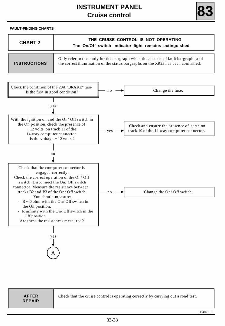
l54021.0
INSTRUMENT PANELCruise control 83
FAULT-FINDING CHARTS
CHART 2THE CRUISE CONTROL IS NOT OPERATING
The On/Off switch indicator light remains extinguished
Only refer to the study for this bargraph when the absence of fault bargraphs andthe correct illumination of the status bargraphs on the XR25 has been confirmed.INSTRUCTIONS
Check that the cruise control is operating correctly by carrying out a road test.AFTERREPAIR
no Change the fuse.
yes
yesCheck and ensure the presence of earth ontrack 10 of the 14-way computer connector.
With the ignition on and the On/Off switch inthe On position, check the presence of
~ 12 volts on track 11 of the14-way computer connector.
Is the voltage ~ 12 volts ?
Check the condition of the 20A "BRAKE" fuseIs the fuse in good condition?
no
no Change the On/Off switch.
A
yes
Check that the computer connector isengaged correctly.
Check the correct operation of the On/Offswitch. Disconnect the On/Off switch
connector. Measure the resistance betweentracks B2 and B3 of the On/Off switch.
You should measure:- R ~ 0 ohm with the On/Off switch in
the On position,- R infinity with the On/Off switch in the
Off positionAre these the resistances measured?
83-38
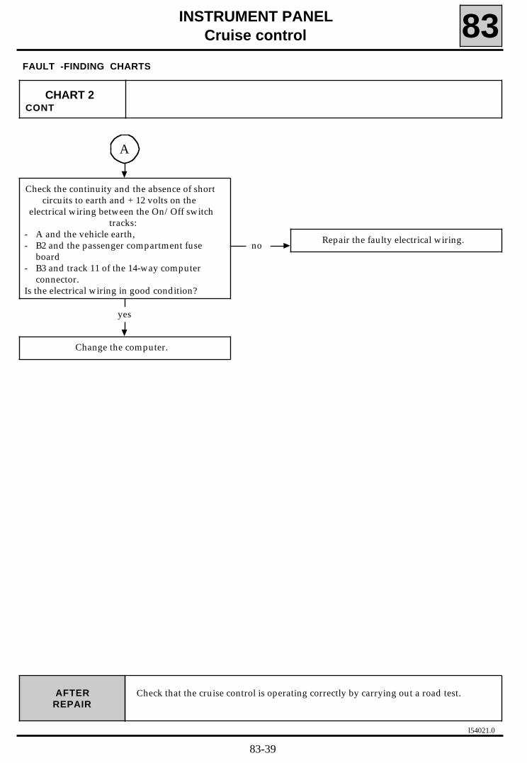
l54021.0
INSTRUMENT PANELCruise control 83
FAULT -FINDING CHARTS
Check that the cruise control is operating correctly by carrying out a road test.AFTERREPAIR
CHART 2CONT
A
no Repair the faulty electrical wiring.
yes
Change the computer.
Check the continuity and the absence of shortcircuits to earth and + 12 volts on the
electrical wiring between the On/Off switchtracks:
- A and the vehicle earth,- B2 and the passenger compartment fuse
board- B3 and track 11 of the 14-way computer
connector.Is the electrical wiring in good condition?
83-39

A
yes
l54021.0
INSTRUMENT PANELCruise control 83
FAULT-FINDING CHARTS
CHART 3THE CRUISE CONTROL IS NOT OPERATING
The On/Off switch indicator light is illuminated
Only refer to the study for this bargraph when the absence of fault bargraphs andthe correct illumination of the status bargraphs on the XR25 has been confirmed.INSTRUCTIONS
Check that the cruise control is operating correctly by carrying out a road test.AFTERREPAIR
noRefer to:
- Chart 5 if the vehicle is fitted with amanual gearbox,
- Chart 7 if the vehicle is fitted with an automatic transmission.
yes
yes Check the setting of the brake switch.
With the ignition on and the On/Off switch inthe On position, check the presence of
~ 12 volts between tracks 3 and 10 of the 14-way computer connector
(without pressing the pedals).Is the voltage ~ 12 volts ?
yes
no
Check:- the condition of the brake light bulbs,- the condition of the electrical wiring
between the passenger compartment fusebox and the cruise control computer, thebrake lights via the filament failure unit.
As before, check that 12 volts is not presenton track 7 of the 14-way computer
connector.Is the voltage ~ 12 volts ?
yes
no Repair the faulty electrical wiring.
Check the continuity and the absence of shortcircuits to earth and to + 12 volts on the
electrical wiring between the cruise controlcomputer connector tracks:
- 1 and5 electropump- 9 and4 assembly- 12 and3 connector
Is the electrical wiring in good condition?
Check whether the brake lights come onwhen the brake pedal is pressed.
Do the brake lights come on?
83-40

B
yes
l54021.0
INSTRUMENT PANELCruise control 83
FAULT-FINDING - FAULT-FINDING CHARTS
Check that the cruise control is operating correctly by carrying out a road test.AFTERREPAIR
CHART 3CONT 1
A
no Change the electropump assembly.
With the ignition off, disconnect the 14-waycomputer connector.
Measure the resistance of the vacuum pump(take the measurement at the wiring end of
the connector) between tracks 1 and 9(positioning the multimeter earth at track 1).
Is the resistance 8 ohms < R < 50 ohms ?
yes
no Change the electropump assembly.
yes
With the ignition off, disconnect the cruisecontrol computer connector.
Using a multimeter, measure the resistance ofthe cruise control solenoid valve (take the
measurement at the wiring end of theconnector) between tracks 12 and 1 of theconnector (position the multimeter earth
point at track 1 of the connector).The resistance should be R ~ 100 ohms.
Is the resistance R ~ 100 ohms ?
no Change the electropump assembly.
With the ignition on and the On/Off switch inthe On position, apply + 12 volts on track 1 of
the computer then check that the vacuumpump is operating correctly (check by
listening to the pump). Is the vacuum pump operating?
83-41

l54021.0
INSTRUMENT PANELCruise control 83
FAULT-FINDING CHARTS
Check that the cruise control is operating correctly by carrying out a road test.AFTERREPAIR
CHART 3CONT 2
B
no Change the electropump assembly.
yes
no Repair or change the faulty component.
With the ignition still off, using a multimeter, measure the resistance of
the safety solenoid valve (take themeasurement at the wiring end of the
connector) between tracks 7 and 1 of theconnector (position the earth point of themultimeter at track 7 of the connector).The resistance should be R ~ 100 ohms.
Is the resistance R ~ 100 ohms ?
yes
no
Repair the mechanical link or set it correctly.(refer to the "Fitting and Setting the
Mechanical Control" section).
Check the condition of the pneumatic part ofthe circuit:
- pipe (sealing),- ram (sealing, setting).
Are these components in good condition?
yes
Change the computer.
Check the condition of the mechanical linkbetween the ram and the throttle.
Is the mechanical link in good condition?
83-42

l54021.0
INSTRUMENT PANELCruise control 83
FAULT-FINDING CHARTS
CHART 4THE SWITCHES ( / ) and (O/R - O/R) ON THE STEERING
WHEEL ARE NOT OPERATING
Only refer to the study for this bargraph when the absence of fault bargraphs andthe correct illumination of the status bargraphs on the XR25 has been confirmed.INSTRUCTIONS
Check that the steering wheel switches are operating correctly.AFTERREPAIR
Check the continuity and and the absence ofshort circuits to earth and to + 12 volts on the
electrical wiring between :
5 and 26 and 1
Is the electrical wiring in good condition?
steeringwheel switchesconnector
computer
no
Disconnect the 14-way cruise controlcomputer connector. With the ignition off,using a multimeter, measure the resistance
between tracks 5 and 6 of this connector(take the measurement at the wiring end of
the connector).- with switch ( ) released, check the pre-
sence of the resistance R infinity- with switch ( ) pressed, check the pre-
sence of the resistance R ~ 260 ± 10ohms.
- with switch ( ) released, check thepresence of the resistance R infinity,
- with switch ( )pressed, check the pre-sence of the resistance R ~ 0 ohm.
- with switch (O/R - O/R)released, checkthe presence of the resistance R infinity
- with switch (O/R - O/R) permanentlypressed, check the presence of the resi-stance R ~ 909 ± 10 ohms.
Are these resistances present?
Change the steering wheel switches.
yes
yes Change the cruise control computer.
no Repair the electrical wiring.
83-43

yes
l54021.0
INSTRUMENT PANELCruise control 83
FAULT-FINDING CHARTS
CHART 5THE CRUISE CONTROL IS NOT CANCELLED BY THE CLUTCH PEDAL
(Fault-finding for vehicles fitted with a manual gearbox)
Only refer to the study for this bargraph when the absence of fault bargraphs andthe correct illumination of the status bargraphs on the XR25 has been confirmed.INSTRUCTIONS
By carrying out a road test, check that the cruise control is cancelled when theclutch pedal is pressed.
AFTERREPAIR
no Change the cruise controlcomputer.
Connect the XR25. Use fiche n°58. Unclip thewire of track 3 of the 14-way cruise controlcomputer connector, then check whether
left-hand bargraph 4 illuminates.Does left-hand bargraph 4 illuminate?
no Set these switches correctly.
yes
no Change the two switches.
Check whether the cruise controlclutch and brake switches are
set correctly.Are these switches set correctly?
yes
Repair the electrical wiring between track 3of the cruise control computer and track B3 of
the On/Off switch via the switch(es).
Check the condition of the cruise controlclutch and brake switches.
Disconnect the switches, then , using amultimeter, measure the resistance between
the tracks (take the measurement at theconnector end of the switch):
- 1 and 3 of the 3 track cruise control clutchswitch connector operating the clutch pe-dal
- 1 and 3 of the 3 track cruise control brakeswitch connector operating the brake pe-dal.
The resistance should be R infinity. Is the resistance R infinity ?
83-44

l54021.0
INSTRUMENT PANELCruise control 83
FAULT-FINDING CHARTS
CHART 6THE CRUISE CONTROL IS NOT CANCELLED BY THE BRAKE PEDAL
(Fault-finding for vehicles fitted with a manual gearbox)
Only refer to the study for this bargraph when the absence of fault bargraphs andthe correct illumination of the status bargraphs on the XR25 has been confirmed.INSTRUCTIONS
By carrying out a road test, check that the cruise control is cancelled when thebrake pedal is pressed.
AFTERREPAIR
no Change the cruise controlcomputer.
Connect the XR25. Use fiche n°58.Unclip the wire of track 3 of the 14-way
cruise control computer, then check whetherleft-hand bargraph 4 illuminates.
Does left-hand bargraph 4 illuminate?
yes
no B
yes
no Set these switches correctly.
With the ignition on, the On/Off switch in theOn position and the brake pedal pressed,check the presence of ~ 12 volts betweentracks 7 and 10 of the 14-way computer
connector.Is the voltage ~ 12 volts ?
A
yes
Check that the cruise control clutch and brakeswitches are set correctly.
Are these switches set correctly?
83-45

l54021.0
INSTRUMENT PANELCruise control 83
FAULT-FINDING CHARTS
By carrying out a road test, check that the cruise control is cancelled when thebrake pedal is pressed.
AFTERREPAIR
CHART 6CONT 1
A
no Change the switches.
Check the condition of the cruise controlclutch and brake switches.
Disconnect the switches, then, using a multimeter, measure the
resistance between tracks (take themeasurements at the connector
end of the switch):- 1 and 3 of the 3 track cruise control clutch
switch connector, operating the clutch pe-dal
- 1 and 3 of the 3 track cruise control brakeswitch connector, operating the brake pe-dal
The resistance should be R infinity.Is the resistance R infinity ?
yes
Check the continuity of the electrical wiringbetween track 3 of the 14-way computer
connector and track B3 of the On/Off switchvia the switches
Repair the electrical wiring.
83-46

l54021.0
INSTRUMENT PANELCruise control 83
FAULT-FINDING CHARTS
By carrying out a road test, check that the cruise control is cancelled when thebrake pedal is pressed.
AFTERREPAIR
CHART 6CONT 2
B
no Set the brake switch.
yes
no
Check: - the brake light bulbs,
- the electrical wiring between thepassenger compartment fuse box and thecruise control computer, the brake lights
via the filament fault box.
Check whether the brake lights come onwhen the brake pedal is pressed.
Do the brake lights come on?
Check that the brake pedal is set correctly.Is the brake pedal set correctly?
yes
no Repair the electrical wiring.
Check the continuity of the electrical wiringbetween the passenger compartment fuseboard and track 7 of the 14-way computer
connector via the brake switch.Is the electrical wiring in good condition?
yes
Change the computer.
83-47

l54021.0
INSTRUMENT PANELCruise control 83
FAULT-FINDING CHARTS
CHART 7THE CRUISE CONTROL IS NOT CANCELLED BY THE BRAKE PEDAL
(Fault-finding for vehicles fitted with automatic transmission)
Only refer to the study for this bargraph when the absence of fault bargraphs andthe correct illumination of the status bargraphs on the XR25 has been confirmed.INSTRUCTIONS
By carrying out a road test, check that the cruise control is cancelled when thebrake pedal is pressed.
AFTERREPAIR
no Change the cruise controlcomputer.
Connect the XR25. Use fiche n°58.Unclip the wire of track 3 of the 14-way cruise
control computer connector.then check whether left-hand bargraph 4
illuminates.Does left-hand bargraph 4 illuminate?
yes
no B
yes
no Set this switch correctly.
With the ignition on, the On/Off switch in theOn position and the brake pedal pressed, check the presence of ~ 12 volts betweentracks 7 and 10 of the 14-way computer
connector.Is the voltage ~ 12 volts ?
A
yes
Check that the cruise control brake switch isset correctly.
Is this switch set correctly?
83-48

l54021.0
INSTRUMENT PANELCruise control 83
FAULT-FINDING CHARTS
By carrying out a road test, check by driving that the cruise control is cancelledwhen the brake pedal is pressed.
AFTERREPAIR
CHART 7CONT 1
A
no Change the cruise controlbrake switch.
Check the condition of the cruise controlbrake switch.
Disconnect the switch, then, using amultimeter, measure the resistance between
tracks (take the measurements at theconnector end of the switch):
- 1 and 3 of the 3 track cruise control brakebrake switch connector, operating the
brake pedal.The resistance should be R infinity.
Is the resistance R infinity ?
yes
Repair the electrical wiring between track 3of the cruise control computer connector and
track B3 of the On/Off switch via the cruisecontrol brake switch.
83-49

l54021.0
INSTRUMENT PANELCruise control 83
FAULT-FINDING CHARTS
By carrying out a road test, check that the cruise control is cancelled when thebrake pedal is pressed.
AFTERREPAIR
CHART 7CONT 2
B
no Set the brake switch.
yes
no
Check:- the brake light bulbs,- the electrical wiring between the
passenger compartment fuse box and thecruise control computer , the brake lightsvia the filament failure unit.
Check whether the brake lights come onwhen the brake pedal is pressed.
Do the brake lights come on?
Check that the brake switch is set correctly.Is the brake switch set correctly?
yes
no Repair the electrical wiring.
Check the continuity of the electrical wiringbetween the passenger compartment fuse
box and track 7 of the 14-way computerconnector via the brake switch.
Is the electrical wiring in good condition?
yes
Change the computer.
83-50
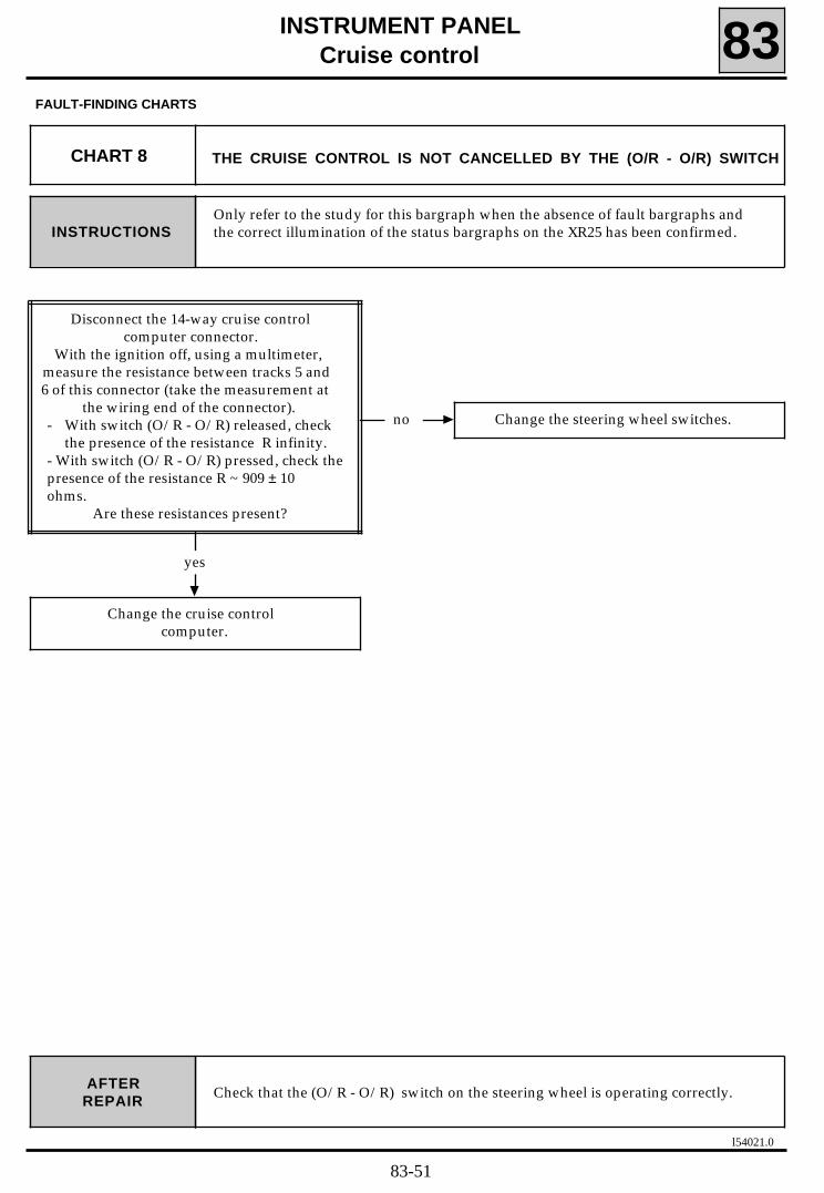
l54021.0
INSTRUMENT PANELCruise control 83
FAULT-FINDING CHARTS
CHART 8 THE CRUISE CONTROL IS NOT CANCELLED BY THE (O/R - O/R) SWITCH
Only refer to the study for this bargraph when the absence of fault bargraphs andthe correct illumination of the status bargraphs on the XR25 has been confirmed.INSTRUCTIONS
Check that the (O/R - O/R) switch on the steering wheel is operating correctly.AFTERREPAIR
yes
no Change the steering wheel switches.
Change the cruise control computer.
Disconnect the 14-way cruise controlcomputer connector.
With the ignition off, using a multimeter,measure the resistance between tracks 5 and6 of this connector (take the measurement at
the wiring end of the connector).- With switch (O/R - O/R) released, check
the presence of the resistance R infinity.- With switch (O/R - O/R) pressed, check thepresence of the resistance R ~ 909 ± 10ohms.
Are these resistances present?
83-51

l54021.0
INSTRUMENT PANEL
Cruise control 83FAULT-FINDING CHARTS
CHART 9THE PREVIOUSLY STORED SPEED CANNOT BE RECALLED
USING THE (O/R - O/R) SWITCH
Only refer to the study for this bargraph when the absence of fault bargraphs andthe correct illumination of the status bargraphs on the XR25 has been confirmed.INSTRUCTIONS
Check that the (O/R - O/R) switch on the steering wheel is operating correctly.AFTERREPAIR
yes
no Change the steering wheel switches.
Change the cruise controlcomputer
Disconnect the 14-way cruise controlcomputer connector.
With the ignition off, using a multimeter,measure the resistance between tracks 5 and6 of this connector (take the measurement at
the wiring end of the connector).- With switch (O/R - O/R) released, check
the presence of the R infinity.- With switch (O/R - O/R) permanently pres-
sed, check the presence of the resistanceR ~ 909 ± 10 ohms.
Are these resistances present?
83-52

l54021.0
INSTRUMENT PANEL
Cruise control 83FAULT-FINDING CHARTS
CHART 10NO CRUISING SPEED
CAN BE STORED USING THE ( / ) SWITCH
Only refer to the study for this bargraph when the absence of fault bargraphs andthe correct illumination of the status bargraphs on the XR25 has been confirmed.INSTRUCTIONS
Check that steering wheel switch ( / ) is operating correctly.AFTERREPAIR
yes
no Change the steering wheel switches.
Change the cruise control computer.
Disconnect the 14-way cruise controlcomputer connector.
With the ignition off, using a multimeter,measure the resistance between tracks 5 and6 of this connector (take the measurement at
the wiring end of the connector).- with switch ( ) released, check the
presence of the resistance R infinity,- with switch( )pressed, check the pre-
sence of the resistance R ~ 260 ± 10ohms.
- with switch ( ) released, check the pre-sence of the resistance R infinity,
- with switch ( ) pressed, check thepresence of the resistance R ~ 0 ohm.
Are these resistances present?
83-53

l54021.0
INSTRUMENT PANELCruise control 83
FAULT-FINDING CHARTS
CHART 11THE STORED SPEED CANNOT BE
INCREASED USING THE( ) SWITCH
Only refer to the study for this bargraph when the absence of fault bargraphs andthe correct illumination of the status bargraphs on the XR25 has been confirmed.INSTRUCTIONS
Check that the steering wheel switch ( ) is operating correctly.AFTERREPAIR
yes
no Change the steering wheel switches.
Change the cruise control computer.
Disconnect the 14-way cruise controlcomputer connector.
With the ignition off, using a multimeter,measure the resistance between tracks 5 and6 of this connector (take the measurement at
the wiring end of the connector).- with switch ( ) released, check the pre-
sence of the resistance R infinity,- with switch ( )pressed, check the pre-
sence of the resistance R ~ 260 ± 10ohms.
Are these resistances present?
83-54

l54021.0
INSTRUMENT PANELCruise Control 83
FAULT-FINDING CHARTS
CHART 12THE STORED SPEED CANNOT BE
REDUCED USING THE ( ) SWITCH
Only refer to the study for this bargraph when the absence of fault bargraphs andthe correct illumination of the status bargraphs on the XR25 has been confirmed.INSTRUCTIONS
AFTERREPAIR
yes
no Change the steering wheel switches.
Change the cruise control computer.
Disconnect the 14-way cruise controlcomputer connector.
With the ignition off, using a multimeter,measure the resistance between tracks 5 and6 of this connector (take the measurement at
the wiring end of the connector).- with switch ( ) released, check the
presence of the resistance R infinity- with switch ( ) pressed, check the pre-
sence of the resistance R ~ 0 ohm.Are these resistances present?
Check that the steering wheel switch ( ) is operating correctly.
83-55

l54021.0
INSTRUMENT PANELCruise control 83
FAULT-FINDING CHARTS
CHART 13 NONE OF THE STEERING WHEEL SWITCHES ARE OPERATING
Only refer to the study for this bargraph when the absence of fault bargraphs andthe correct illumination of the status bargraphs on the XR25 has been confirmed.INSTRUCTIONS
Check that the steering wheel switches are operating correctly.AFTERREPAIR
no
yes Change the cruise controlcomputer.
Disconnect the 14-way cruise controlcomputer connector.
With the ignition off, using a multimeter,measure the resistance between tracks 5 and6 of this connector (take the measurement at
the wiring end of the connector).- with switch ( ) released, check the
presence of the resistance R infinity,- with switch ( ) pressed, check the pre-
sence of the resistance R ~ 260 ± 10ohms.
- with switch ( ) released, check the pre-sence of the resistance R infinity,
- with switch ( ) pressed, check the pre-sence of the resistance R ~ 0 ohm.
- with switch (O/R - O/R) released, checkthe presence of the resistance R infinity,
- with switch (O/R - O/R) pressed, checkthe presence of the resistance R ~ 909 ±10 ohms.
Are these resistances present?
A
yes
Check the condition of the rotary switchunder the steering wheel.
Is the rotary switch in good condition?no Change the rotary switch under the steering
wheel.
83-56

l54021.0
INSTRUMENT PANEL
Cruise control 83FAULT-FINDING CHARTS
Check that the steering wheel switches are operating correctly.AFTERREPAIR
CHART 13CONT
A
Check the continuity and absence of shortcircuits to earth and to 12 volts on the
electrical wiring between the cruise controlcomputer connector tracks:
5 and 26 and 1
Is the electrical wiring in good condition?
of the steeringwheel switchesconnector
Change the steering wheel switches.
yes
no Repair the electrical wiring.
83-57

INSTRUMENT PANELCruise Control 83
CONFORMITY CHECK
INSTRUCTIONSIf a fault bargraph is illuminated, refer to the corresponding fault-finding chart.
Order ofoperations
Function to bechecked
Action BargraphDisplay and
notes
1 XR25 dialogueD58
(selectoron S8)
u 1 tthen 2. u 1 t
Use fiche n° 58
2Interpretation of
bargraphsilluminated normally
Code present
3Computerconformity G70*
X X X
Part Number displayed in threesequences.
4 Action on the pedals
Illuminated if the brake pedalor the clutch pedal (manual
gearbox) (or both) is operated
Illuminated when the brakelights come on (brake pedal
operated)
5Gear lever positioncheck (automatic
transmission)
Illuminated with gear lever is in"Park" or "Neutral" position
(automatic transmission)
6Steering wheel
control buttons check
Illuminated when thebutton of the left-hand switch
( / ) is pressed.
Illuminated when the button of the left-hand switch
( / ) is pressed.
Illuminated when the right-hand switch (O/R - O/R) isoperated (on either side).
7Speed thresholdcheck(road test)
Extinguishes when the actualvehicle speed exceeds theminimum threshold for
operation of the cruise control,i.e. 33 km/h (20 m.p.h.)
1
4
5
6
8
9
10
12
83-58

INSTRUMENT PANEL
Cruise control 83INSTRUCTIONS
Do not switch off the ignition before carrying out the additional checks forcommand #11 (not stored).
Order ofoperations
Function to bechecked
Action BargraphDisplay and
notes
8Actual vehicle speed
(road test) # 01 X X X in km/h (m.p.h.)
9Last action which
cancelled the cruisecontrol function
# 11
4 Moving of the gear leverto position "P" or "N"
9 The actual vehicle speed hasfallen below the minimumthreshold for engagementof the cruise control; i.e. 33km/h (20 m.p.h.)
10 Acceleration or decelera-tion of the vehicle greaterthan 4 m/s2
15 Action on the clutch pedal(manual gearbox) and/orthe brake pedal
16 Action on the brake pedal(brake lights line)
19 With the cruise control en-gaged, the vehicle speedhas fallen below 75 %of thespeed stored
25 Steering wheel fault detec-ted by a voltage fault bet-ween tracks 5 and 6 of thecomputer
26 Action on the right-handsteering wheel switch (O/R- O/R)
5, 6, 7, 11, 12, 13, 17, 18, 20, 21,22, 23, 24, 27 and 28
Computer internal fault
83-59
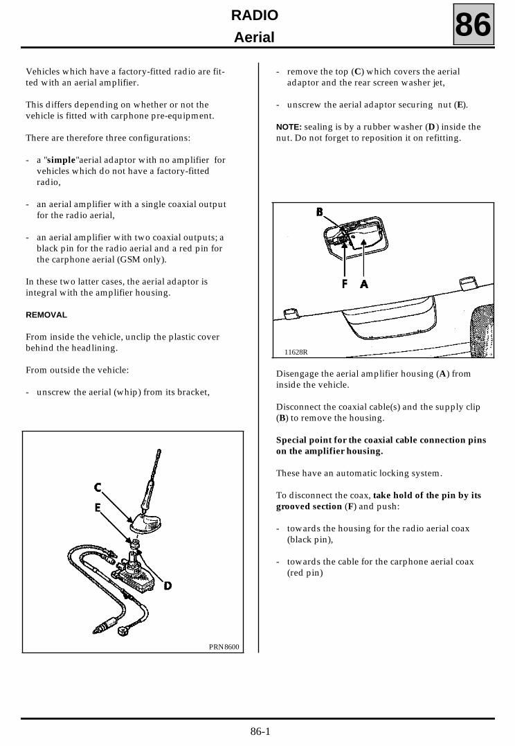
RADIO
Aerial 86Vehicles which have a factory-fitted radio are fit-ted with an aerial amplifier.
This differs depending on whether or not thevehicle is fitted with carphone pre-equipment.
There are therefore three configurations:
- a "simple"aerial adaptor with no amplifier forvehicles which do not have a factory-fittedradio,
- an aerial amplifier with a single coaxial outputfor the radio aerial,
- an aerial amplifier with two coaxial outputs; ablack pin for the radio aerial and a red pin forthe carphone aerial (GSM only).
In these two latter cases, the aerial adaptor isintegral with the amplifier housing.
REMOVAL
From inside the vehicle, unclip the plastic coverbehind the headlining.
From outside the vehicle:
- unscrew the aerial (whip) from its bracket,
- remove the top (C) which covers the aerialadaptor and the rear screen washer jet,
- unscrew the aerial adaptor securing nut (E).
NOTE: sealing is by a rubber washer (D) inside thenut. Do not forget to reposition it on refitting.
PRN8600
11628R
Disengage the aerial amplifier housing (A) frominside the vehicle.
Disconnect the coaxial cable(s) and the supply clip(B) to remove the housing.
Special point for the coaxial cable connection pinson the amplifier housing.
These have an automatic locking system.
To disconnect the coax, take hold of the pin by itsgrooved section (F) and push:
- towards the housing for the radio aerial coax(black pin),
- towards the cable for the carphone aerial coax(red pin)
86-1

WIRING
Storing the driver’s seat positions 88GENERAL
This is a system which is made up of an electricdriver’s seat with position memory, an electricfront passenger seat and electric external rearview mirrors.
The driver of the vehicle has two options:
- positioning as required using an electriccontrol for the various adjustable componentsof the driver’s seat, manual adjustment mode,
- storing or recalling with a single action of all ofthe driver’s seat component settings, automaticadjustment mode.
A computer continually checks the position of theadjustable components of the driver’s seat.
It analyses the driver’s selections and controls themotors of the various components in accordancewith these selections.
NOTE: the stored adjustment mode control padhas no On/Off buttons
DESCRIPTION
• The computer (1)
This is located under the driver’s seat (clipped tothe front of the underframe.
Depending on the way in which it is controlled,this computer has:
- a standby status (inactive),
- a ready status (active).
It changes from the inactive status, to the activestatus by the detection of one of the twofollowing pieces of information:
1) The driver’s door opening information (doorsill switch) which, if it is not preceded bycutting off of the + after ignition, causes thecomputer to become active,
- for 15 seconds in automatic mode (singleaction),
- for 4 minutes for continued pressure.
2) The + after ignition information which causesthe computer to become active until it is cutoff (for continued pressure).
It changes from the active status to the inactivestatus after 4 minutes following the cutting off ofthe + after ignition, or sooner, if a driver’s dooropening/closing cycle is detected (driver leavinghis vehicle).
The computer retains its memory if its permanentsupply is cut off (battery disconnected).
11943R
88-1

WIRING
Storing the driver’s seat positions 88Special points for the passenger’s side externalrear view mirror
A special positioning, in a low passenger’s exter-nal rear view mirror position, is carried out auto-matically when "reverse gear" is engaged.
The low position of the passenger’s external rearview mirror in reverse gear assists the driver whenparking against a kerb.
A personalised position can be stored and addedto one of the three selections: 1, 2 or 3.
Storing:
- engage reverse gear,- adjust the passenger’s external rear view mir-
ror to the required low position (left, right, up,down),
- press the Store button.- press button 1, or 2, or 3 depending on the dri-
ver concerned.
RECALLING THE SETTING
The stored passenger’s external rear view mirrorreversing position corresponding to the latest se-lection 1, or 2, or 3 made by the driver is recalledautomatically when reverse gear is engaged.
If no position is stored the external rear view mir-ror assumes a default position (up/down adjus-tment only).
Note: the external rear view mirrors controlneutral position prevents tilting of thepassenger’s side external rear view mirror whenchanging from reverse gear.
NOTE: operating the starter while the seat ismoving temporarily interrupts any adjustment.
88-2
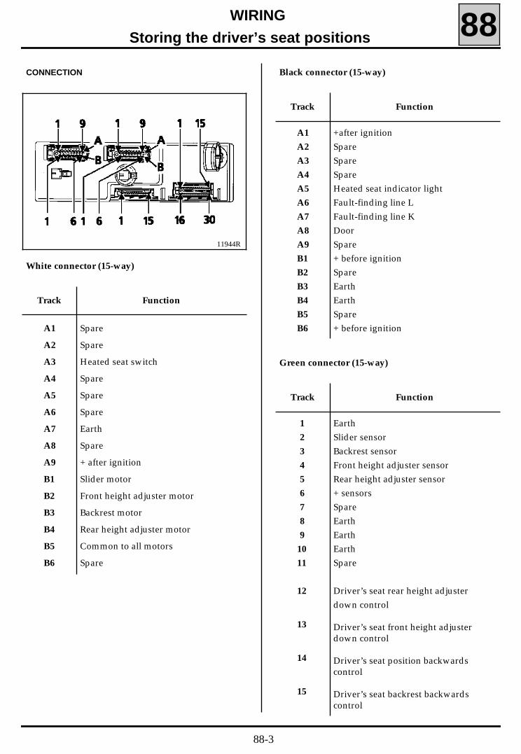
WIRING
Storing the driver’s seat positions 88CONNECTION Black connector (15-way)
11944R
White connector (15-way)
Track Function
A1
A2
A3
A4
A5
A6
A7
A8
A9
B1
B2
B3
B4
B5
B6
Spare
Spare
Heated seat switch
Spare
Spare
Spare
Earth
Spare
+ after ignition
Slider motor
Front height adjuster motor
Backrest motor
Rear height adjuster motor
Common to all motors
Spare
Track Function
A1
A2
A3
A4
A5
A6
A7
A8
A9
B1
B2
B3
B4
B5
B6
+after ignitionSpareSpareSpareHeated seat indicator lightFault-finding line LFault-finding line KDoorSpare+ before ignitionSpareEarthEarthSpare+ before ignition
Green connector (15-way)
Track Function
1
2
3
4
5
6
7
8
9
10
11
12
13
14
15
EarthSlider sensorBackrest sensorFront height adjuster sensorRear height adjuster sensor+ sensorsSpareEarthEarthEarthSpare
Driver’s seat rear height adjusterdown control
Driver’s seat front height adjusterdown control
Driver’s seat position backwardscontrol
Driver’s seat backrest backwardscontrol
88-3

WIRING
Storing the driver’s seat positions 88Brown connector (30-way)
Track Function
12
13
14
15
16
17
18
19
20
21
22
23
24
25
26
27
28
29
30
Driver’s external rear view mirrorup/down motor
Passenger’s external rear view mirrorleft/right motor
Passenger’s external rear view mirrorup/down motor
Common passenger’s external rearview mirror motor
+potentiometers
Spare
Potentiometers earth
Spare
Spare
Spare
Spare
Spare
Spare
Spare
Earth
Earth
Spare
Spare
Spare
Track Function
1
2
3
4
5
6
7
8
9
10
11
Passenger’s external rear view mirrorleft/right control
Driver’s external rear view mirrorleft/right control
Passenger’s external rear view mirrorup/down control
Driver’s external rear view mirrorup/down control
Passenger’s external rear view mirrortilting prevention control
Reverse gear information
Driver’s external rear view mirrorup/down potentiometer
Driver’s external rear view mirrorleft/right potentiometer
Passenger’s external rear view mirrorup/down potentiometer
Passenger’s external rear view mirrorleft/right potentiometer
Driver’s external rear view mirrorleft/right motor
88-4
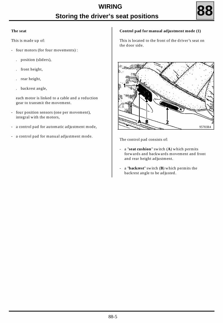
WIRING
Storing the driver’s seat positions 88Control pad for manual adjustment mode (1)
This is located to the front of the driver’s seat onthe door side.
95783R4
The control pad consists of:
- a "seat cushion" switch (A) which permitsforwards and backwards movement and frontand rear height adjustment.
- a "backrest" switch (B) which permits thebackrest angle to be adjusted.
The seat
This is made up of:
- four motors (for four movements) :
. position (sliders),
. front height,
. rear height,
. backrest angle,
each motor is linked to a cable and a reductiongear to transmit the movement.
- four position sensors (one per movement),integral with the motors,
- a control pad for automatic adjustment mode,
- a control pad for manual adjustment mode.
88-5

WIRING
Storing the driver’s seat positions 88Control pad for automatic adjustment mode (2)
The control pad consists of:
- a "Store" push button which permits storing ofthe previously set positions,
- three push buttons 1 - 2 - 3 which permit threedriver’s seat positions to be selected:
. either in storing mode,
. or in recall mode.
Position sensors
There is one sensor for each motor. They are fittedto the end of the axle of each motor.
They continually inform the computer of theexact position of each axle (position, front heightrear height, backrest angle).
CONNECTION
Manual adjustment mode control pad
95784R
Track Function
A1
A2
A3
A4
A5
A6
B1
B2
B3
B4
B5
B6
Front height adjuster downFront height adjuster upBackwards movementRear height adjuster downBackwards backrest controlForwards backrest controlEarthSpareForwards movementRear height adjuster upSpareEarth
Automatic adjustment mode control pad
Track Function
A1
A2
A4
A5
B1
B2
B3
B4
B5
EarthSpareStore button controlCommon store controlsSpare+ after ignition (lights)Button 3 controlButton 2 controlButton 1 control
11942R
88-6

WIRING
Storing the driver’s seat positions 88REMOVING THE CONTROL PADS
Removal
Place the seat in its highest position.
Disconnect the battery.
Remove the three slider cover mounting bolts
Disconnect the control pad connector.
Unclip the control pad.
Refitting
Proceed in the reverse order to removal.
88-7
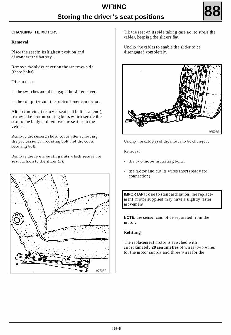
WIRING
Storing the driver’s seat positions 88CHANGING THE MOTORS
Removal
Place the seat in its highest position anddisconnect the battery.
Remove the slider cover on the switches side(three bolts)
Disconnect:
- the switches and disengage the slider cover,
- the computer and the pretensioner connector.
After removing the lower seat belt bolt (seat end),remove the four mounting bolts which secure theseat to the body and remove the seat from thevehicle.
Remove the second slider cover after removingthe pretensioner mounting bolt and the coversecuring bolt.
Remove the five mounting nuts which secure theseat cushion to the slider (F).
97526S
Tilt the seat on its side taking care not to stress thecables, keeping the sliders flat.
Unclip the cables to enable the slider to bedisengaged completely.
97525R
Unclip the cable(s) of the motor to be changed.
Remove:
- the two motor mounting bolts,
- the motor and cut its wires short (ready forconnection)
IMPORTANT: due to standardisation, the replace-ment motor supplied may have a slightly fastermovement.
NOTE: the sensor cannot be separated from themotor.
Refitting
The replacement motor is supplied withapproximately 20 centimetres of wires (two wiresfor the motor supply and three wires for the
88-8

WIRING
Storing the driver’s seat positions 88Connection to the seat cables must be carried outusing heat-shrink sleeves with a metal core (referto P.R. 830 and the procedure in N.T. 8075) in ac-cordance with the colours of the wires.
In order to spread out the connections, the fivemotor/sensor assembly wires must be cut aatdifferent lengths in order to stagger the points toprevent bunching of the connections.
Position the new motor paying attention to therouting of the wiring and check that each wire iscorrectly insulated (protect the wiring usingadhesive tape).
Refit the seat in the reverse order to removal.
CHANGING THE CABLES
The cables can only be changed after the seat hasbeen removed and the sliders have beenseparated from the frame. Refer to the procedurefor the removal of motors.
Removal
Disengage connectors (A) and (B).
11941R
Cut the five wires of the four motors as close aspossible to the cables in order to leave as muchlength as possible attached to the motor.
Disengage the cables.
Fit heat-shrink sleeves with a metal core (refer toP.R. 830 and N.T. 8075) to the motor wiresspreading the connections.
Refitting
Fit the new cables.
88-9

WIRING
Storing the driver’s seat positions 88Connect the motors to the cables in accordancewith the colour of the wires and separating thesleeves as much as possible.
Check the bulkiness of the repair to ensure thatcorrect movement of the seat/sliders.
Refit the seat in the reverse order to removal.
IMPORTANT NOTE
Work carried out on the motors or the cables hasno effect of the operation of the seat. Noadjustment is necessary following theseoperations.
However, removal or refitting of a axle or a slidermay alter the original setting.
In this case, so that the customer is not surprisedat finding settings which are not his own, it isadvisable to reinitialise the computer following
COMPUTER REINITIALISATION PROCEDURE
This procedure enables all of the stored positionsto be erased from the computer (refer to the noteopposite).
- Connect the XR25 to the vehicle diagnosticssocket and position the rotary selector at S8.
- Enter the code
- The following will be displayed:
then
- Enter the code
Bleeping of the XR25 confirms that the seatposition memory has been erased.
D 1 6
G 8 0 * *
88-10

WIRING
Storing the driver’s seat positions 88Diagram
PRN8800
88-11

WIRING
Storing the driver’s seat positions 88FAULT-FINDING
In the event of a driver’s seat setting memoryfault, refer to the fault chart which corresponds tothe fault, then connect the XR25 and follow thefault chart.
CONNECTING THE XR25
92656S
Connect the XR25 to the vehicle diagnosticssocket and place the selector in position S8.
92655R2
NOTE: the indicator light "V" must beextinguished. If it is illuminated, disconnect andthen reconnect the diagnostics socket. If itremains illuminated, check the XR25 wiring andthe battery voltage.
88-12

FAULT-FINDING - INTRODUCTION
PRECAUTION:
When carrying out checks using the multimeter, avoid using a contact point on the connectors the size ofwhich may damage the clips and result in poor contact. For all measurements and checks carried out onthe brown 30-way connector and the green 15-way connector, bornier Elé. 1302 must be used.
Bornier Elé. 1302 enables:
- the continuities to be checked. To do this, simply connect the bornier to the 30-way instrument panelconnector or to the connector at the vehicle wiring end.
- measure the voltages, frequencies etc... To do this, connect the bornier in parallel between thecomputer and the connector at the vehicle wiring end.
K54021.0
WIRING
Storing the driver’s seat positions 88
88-13

WIRINGStoring the driver’s seat positions 88
FAULT-FINDING- XR25 FICHE
FI21616-1
Bargraphs on a coloured background represent a fault.Bargraphs on a white background represent a status.
88-14

WIRINGStoring the driver’s seat positions 88
FAULT-FINDING - XR25 FICHE
FI21616-2
Bargraphs on a coloured background represent a fault.Bargraphs on a white background represent a status.
88-15

K54021.0
WIRING Storing the driver’s seat positions 88
FAULT-FINDING - XR25 FICHE
MEANING OF BARGRAPHS
FAULT (always on a coloured background)
If illuminated, this indicates a fault on the unit concerned. The associated textdefines the fault.This bargraph may be :- Illuminated : fault present- Flashing : fault stored- Extinguished : no fault or no fault detected
STATUS (always on a white background)
Bargraph always located top left.If illuminated, this indicates that dialogue has been established with thecomputer of the unit concerned.If it remains extinguished:- The code does not exist.- There is XR25 fault, a computer fault or the XR25 / computer connection isfaulty.
The representation of the following bargraphs indicates their initial status:Initial status: (ignition on, engine stopped, no action by the operator)
Undefinedis illuminated when the function or thecondition defined on the fiche is carried out.
Extinguished
Illuminated is extinguished when the function or thecondition defined on the fiche is not carriedout.
or
88-16

K54021.0
WIRINGStoring the driver’s seat positions 88
FAULT-FINDING - INTERPRETATION OF XR25 BARGRAPHS
When communication is established, deal with any illuminated fault bargraphs.AFTERREPAIR
Right-hand bargraph 1 extinguished
XR25 COMPUTER COMMUNICATION
1
NoneINSTRUCTIONS
Fiche n° 16 side 1/2
Before establishing communication between the XR25 and the computer, check the following condition:- ignition on.
Check the condition of the 25 A "Seat Memory" and 10 A "Clock" fuses.
Change the fuses if necessary.
Check that the XR25 is not the cause of the fault by trying to communicate with a computer on anothervehicle.
Check that the ISO interface in position S8 and that you are using the latest version of the XR25 cassetteand the correct access code (D 16).
Check the battery voltage (U > 10.5 volts). Recharge the battery if necessary.
Check that the computer connectors are engaged correctly.
Check that the computer is correctly supplied:- earth on track B4 and B5 of the black 15-way computer connector,- + before ignition on track B1 of the black 15-way computer connector.
Check that the diagnostics socket is correctly supplied:- earth on track 5- + before ignition on track 16.
Check and if necessary repair the continuity and insulation of the electrical wiring between thediagnostics socket connector and tracks:- 8 of the computer- 14
If there is still no dialogue between the XR25 and the computer, change the computer.
88-17

K54021.0
WIRINGStoring the driver’s seat positions 88
Right-hand bargraph 2 illuminated
ABNORMAL SUPPLY2
Fiche n° 16 side 1/2
FAULT-FINDING - INTERPRETATION OF XR25 BARGRAPHS
NoneINSTRUCTIONS
Check that all of the seat movements are correct.AFTERREPAIR
Check the battery voltage.If it is too low, recharge the battery.
88-18

K54021.0
WIRING
Storing the driver’s seat positions 88
Right-hand bargraph 2 illuminated
UNWANTED MOVEMENT FAULT ON A SEAT AXLE2
Fiche n° 16 side 2/2
FAULT-FINDING - INTERPRETATION OF XR25 BARGRAPHS
NoneINSTRUCTIONS
Enter G0** on the XR25. AFTERREPAIR
If the unwanted movement fault is on the seat position axle, refer to the study for left-hand bargraph 3illuminated on fiche n° 16 side 2/2.
If the unwanted movement fault is on the seat backrest, refer to the study for left-hand bargraph 4illuminated on fiche n° 16 side 2/2.
If the unwanted movement fault is on the seat rear height adjuster, refer to the study for left-handbargraph 5 illuminated on fiche n° 16 side 2/2.
If the unwanted movement fault is on the seat front height adjuster, refer to the study for left-handbargraph 6 illuminated on fiche n° 16 side 2/2.
88-19

K54021.0
WIRINGStoring the driver’s seat positions 88
Left-hand bargraph 3 illuminated
BLOCKING / CO OF THE POSITION MOTORXR25 : * 03 = CO Position motor open circuit
good Position motor good
3Fiche n° 16 side 2/2
FAULT-FINDING - INTERPRETATION OF XR25 BARGRAPHS
Check the condition of the 25 A "Seat memory" fuse on the passengercompartment fuse board.Change the fuse if necessary.Fault-finding: * 03 = CO
INSTRUCTIONS
Enter G0** on the XR25.Check that all of the seat movements are correct.
AFTERREPAIR
Check that nothing is blocking movement of the seat.
Check the continuity and insulation to earth of the electrical wiring between the white 15-way computerconnector tracks:- B1 and position- B5 motor
Repair the electrical wiring if necessary.
Measure the voltage between tracks B1 and B5 of the white 15-way computer connector when themanual control pad position control is operated.The voltage should be: -12 volts < U < +12 volts
Is the voltage within these limits?
Change the position motor.YES
Change the computer.NO
88-20

K54021.0
WIRINGStoring the driver’s seat positions 88
FAULT-FINDING - INTERPRETATION OF XR25 BARGRAPHS
Left-hand bargraph 4 illuminated
BLOCKING / CO OF THE BACKREST MOTORXR25 : * 04 = CO Backrest motor open circuit
good Backrest motor good
4Fiche n° 16 side 2/2
Check the condition of the 25 A "Seat memory" fuse on the passengercompartment fuse board.Change the fuse if necessary.Fault-finding: * 03 = CO
INSTRUCTIONS
Enter G0** on the XR25.
Check that all of the seat movements are correct.
AFTERREPAIR
Check that nothing is blocking movement of the backrest.
Check the continuity and insulation to earth of the electrical wiring between the white 15-way computerconnector tracks:- B3 and backrest- B5 motor
Repair the electrical wiring if necessary.
Measure the voltage between tracks B3 and B5 of the white 15-way computer connector when themanual control pad backrest control is operated.The voltage should be: -12 volts < U < +12 volts
Is the voltage within these limits?
Change the backrest motor.YES
Change the computer.NO
88-21

K54021.0
WIRINGStoring the driver’s seat positions 88
FAULT-FINDING - INTERPRETATION OF XR25 BARGRAPHS
Left-hand bargraph 5 illuminated
BLOCKING / CO OF THE REAR HEIGHT ADJUSTER MOTORXR25 : * 05 = CO Rear height adjuster motor open circuit
good Rear height adjuster good
5Fiche n° 16 side 2/2
Check the condition of the 25 A "Seat memory" fuse on the passengercompartment fuse board.Change the fuse if necessaryFault-finding: * 05 = CO
INSTRUCTIONS
Enter G0** on the XR25.
Check that all of the seat movements are correct.
AFTERREPAIR
Check that nothing is blocking movement of the seat rear height adjuster.
Check the continuity and insulation to earth of the electrical wiring between the white 15-way computerconnector tracks:- B4 and rear height- B5 adjuster motor
Repair the electrical wiring if necessary.
Measure the voltage between tracks B4 and B5 of the white 15-way computer connector when themanual control pad rear height adjuster control is operated.The voltage should be: -12 volts < U < +12 volts
Is the voltage within these limits?
Change the rear height adjuster motor.YES
Change the computer.NO
88-22

K54021.0
WIRING
Storing the driver’s seat positions 88FAULT-FINDING - INTERPRETATION OF XR25 BARGRAPHS
Left-hand bargraph 6 illuminated
BLOCKING / CO OF THE FRONT HEIGHT ADJUSTER MOTORXR25 : * 06 = CO Front height adjuster motor open circuit
good Front height adjuster motor good
6Fiche n° 16 side 2/2
Check the condition of the 25 A "Seat memory" fuse on the passengercompartment fuse board.Change the fuse if necessary.Fault-finding: * 06 = CO
INSTRUCTIONS
Enter G0** on the XR25.Check that all of the seat movements are correct.
AFTERREPAIR
Check that nothing is blocking movement of the seat front height adjuster.
Check the continuity and insulation to earth of the electrical wiring between the white 15-way computerconnector tracks:- B2 and front height- B5 adjuster motor
Repair the electrical wiring if necessary.
Measure the voltage between tracks B2 and B5 of the white 15-way computer connector when themanual control pad front height adjuster control is operated.The voltage should be: -12 volts < U < +12 voltsIs the voltage within these limits?
Change the front height adjuster motor.YES
Change the computer.NO
88-23
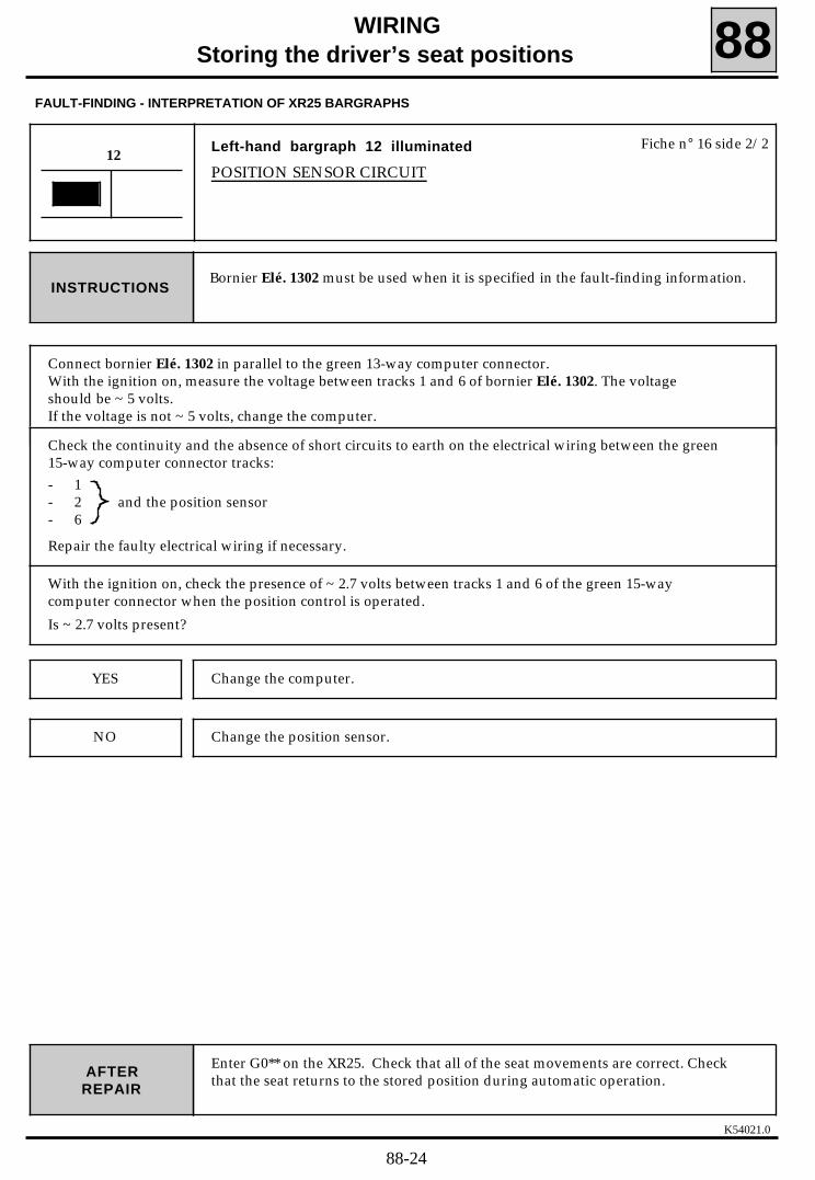
K54021.0
WIRINGStoring the driver’s seat positions 88
Left-hand bargraph 12 illuminated
POSITION SENSOR CIRCUIT12
Fiche n° 16 side 2/2
FAULT-FINDING - INTERPRETATION OF XR25 BARGRAPHS
Bornier Elé. 1302 must be used when it is specified in the fault-finding information.INSTRUCTIONS
Enter G0** on the XR25. Check that all of the seat movements are correct. Checkthat the seat returns to the stored position during automatic operation.AFTER
REPAIR
Connect bornier Elé. 1302 in parallel to the green 13-way computer connector.With the ignition on, measure the voltage between tracks 1 and 6 of bornier Elé. 1302. The voltageshould be ~ 5 volts.If the voltage is not ~ 5 volts, change the computer.
Check the continuity and the absence of short circuits to earth on the electrical wiring between the green15-way computer connector tracks:- 1- 2 and the position sensor- 6
Repair the faulty electrical wiring if necessary.
With the ignition on, check the presence of ~ 2.7 volts between tracks 1 and 6 of the green 15-way computer connector when the position control is operated.
Is ~ 2.7 volts present?
Change the computer.YES
Change the position sensor.NO
88-24

K54021.0
WIRINGStoring the driver’s seat positions 88
FAULT-FINDING - INTERPRETATION OF XR25 BARGRAPHS
Right-hand bargraph 12 illuminated
BACKREST SENSOR CIRCUIT12
Fiche n° 16 side 2/2
Bornier Elé. 1302 must be used when it is specified in the fault-finding information.INSTRUCTIONS
Enter G0** on the XR25. Check that all of the seat movements are correct. Checkthat the seat returns to the stored position during automatic operation.AFTER
REPAIR
Connect bornier Elé. 1302 in parallel to the green 13-way computer connector.With the ignition on, measure the voltage between tracks 1 and 6 of bornier Elé. 1302. The voltageshould be ~ 5 volts.If the voltage is not ~ 5 volts, change the computer.
Check the continuity and the absence of short circuits to earth on the electrical wiring between the green15-way computer connector tracks:- 1- 3 and the backrest sensor- 6
Repair the electrical wiring if necessary.
With the ignition on, check the presence of ~ 2.7 volts between tracks 3 and 6 of the green 15-way computer connector when the backrest control is operated.
Is ~ 2.7 volts present?
Change the computer.YES
Change the backrest position sensor.NO
88-25

K54021.0
WIRING
Storing the driver’s seat positions 88FAULT-FINDING - INTERPRETATION OF XR25 BARGRAPHS
Left-hand bargraph 13 illuminated
FRONT HEIGHT SENSOR CIRCUIT13
Fiche n° 16 side 2/2
Bornier Elé. 1302 must be used when it is specified in the fault-finding information.INSTRUCTIONS
Enter G0** on the XR25. Check that all of the seat movements are correct. Checkthat the seat returns to the stored position during automatic operation.AFTER
REPAIR
Connect bornier Elé. 1302 in parallel to the green 13-way computer connector.With the ignition on, measure the voltage between tracks 1 and 6 of bornier Elé. 1302. The voltageshould be ~ 5 volts.If the voltage is not ~ 5 volts, change the computer.
Check the continuity and the absence of short circuits to earth on the electrical wiring between the green15-way computer connector tracks:- 1- 4 and the front height sensor- 6
Repair the electrical wiring if necessary.
With the ignition on, check the presence of ~ 2.7 volts between tracks 4 and 6 of the green 15-way computer connector when the front height adjuster control is operated.
Is ~ 2.7 volts present?
Change the computer.YES
Change the front height sensor.NO
88-26
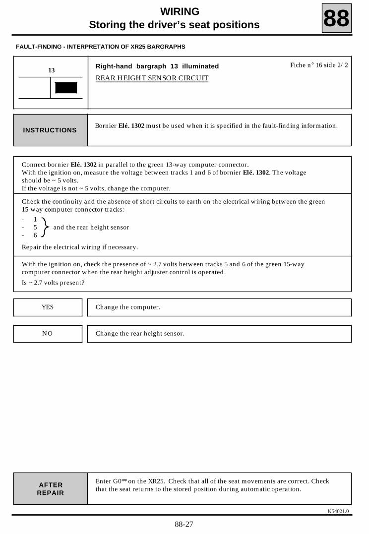
K54021.0
WIRINGStoring the driver’s seat positions 88
FAULT-FINDING - INTERPRETATION OF XR25 BARGRAPHS
Right-hand bargraph 13 illuminated
REAR HEIGHT SENSOR CIRCUIT13
Fiche n° 16 side 2/2
Bornier Elé. 1302 must be used when it is specified in the fault-finding information.INSTRUCTIONS
Enter G0** on the XR25. Check that all of the seat movements are correct. Checkthat the seat returns to the stored position during automatic operation.AFTER
REPAIR
Connect bornier Elé. 1302 in parallel to the green 13-way computer connector.With the ignition on, measure the voltage between tracks 1 and 6 of bornier Elé. 1302. The voltageshould be ~ 5 volts.If the voltage is not ~ 5 volts, change the computer.
Check the continuity and the absence of short circuits to earth on the electrical wiring between the green15-way computer connector tracks:- 1- 5 and the rear height sensor- 6
Repair the electrical wiring if necessary.
With the ignition on, check the presence of ~ 2.7 volts between tracks 5 and 6 of the green 15-way computer connector when the rear height adjuster control is operated.
Is ~ 2.7 volts present?
Change the computer.YES
Change the rear height sensor.NO
88-27

K54021.0
WIRINGStoring the driver’s seat positions 88
Left-hand bargraph 16 illuminated
DRIVER OR PASSENGER EXTERNAL REAR VIEW MIRROR MOTORXR25 : * 16 = 1.dEF passenger’s external rear view mirror
2.dEF driver’s external rear view mirror3.dEF common to all external rear view mirror motors
16Fiche n° 16 side 2/2
FAULT-FINDING - INTERPRETATION OF XR25 BARGRAPHS
Enter *16 on the XR25 to determine to which external rear view mirror the fault-finding procedure should be applied. INSTRUCTIONS
Enter G0** on the XR25. Check that all of the external rear view mirrormovements are correct. Check that the external rear view mirrors return to theirstored position during automatic operation.
AFTERREPAIR
If the motor has an up/down passenger’s external rear view mirror movement fault, consult the study forleft-hand bargraph 17 illuminated on fiche n° 16 side 2/2.
If the motor has a right/left passenger’s external rear view mirror movement fault, consult the study forleft-hand bargraph 18 illuminated on fiche n° 16 side 2/2.
Fault-finding: *16 = 1.dEF passenger’s external rear view mirrormotor
INSTRUCTIONS*16 = 1.dEF
If the motor has an up/down driver’s external rear view mirror movement fault, consult the study for left-hand bargraph 19 illuminated on fiche n° 16 side 2/2.
If the motor has a right/left driver’s external rear view mirror movement fault, consult the study for left-hand bargraph 20 illuminated on fiche n° 16 side 2/2.
Fault-finding: *16 = 2.dEF driver’s external rear view mirrormotor
INSTRUCTIONS*16 = 2.dEF
88-28

K54021.0
WIRINGStoring the driver’s seat positions 88
FAULT-FINDING - INTERPRETATION OF XR25 BARGRAPHS
Enter G0** on the XR25. Check that all of the external rear view mirrormovements are correct. Check that the external rear view mirrors return to theirstored position during automatic operation.
AFTERREPAIR
CONT
16
Bornier Elé. 1302 must be used when it is specified in the fault-finding information. INSTRUCTIONS*16 = 3.dEF
Check the continuity and absence of short circuits to earth on the electrical wiring between the brown 30-way computer connector tracks:- 11 and the driver’s external rear view mirror right/left motor- 12 and the driver’s external rear view mirror up/down motor- 13 and the passenger’s external rear view mirror right/left motor- 14 and the passenger’s external rear view mirror up/down motor- 15 and the common external rear view mirrors motors
Repair the electrical wiring if necessary.
Connect bornier Elé. 1302 to the brown 30-way computer connector.
Switch on the ignition. To bornier Elé. 1302, connect:- + after ignition to track 11 earth to track 15. The driver’s external rear view mirror mirror should move
on the right/left axle.- + after ignition to track 12 and earth to track 15. The driver’s external rear view mirror should move
on the up/down axle.- + after ignition to track 13 and earth to track 15. The passenger’s external rear view mirror should
move on the right/left axle.- + after ignition to track 14 and earth to track 15. The passenger’s external rear view mirror should
move on the up/down axle.
If the external rear view mirrors do not move on the up/down or right/left axles, change the faultyexternal rear view mirror(s)
Follow the same procedure as above, connecting to bornier Elé. 1302 :- + after ignition to track 15 and earth to track 11. The driver’s external rear view mirror should move
on the right/left axle.- + after ignition to track 15 and earth to track 12. The driver’s external rear view mirror should move
on the up/down axle.- + after ignition to track 15 and earth to track 13. The passenger’s external rear view mirror should
move on the right/left axle.- + after ignition to track 15 and earth to track 14. The passenger’s external rear view mirror should
move on the up/down axle.Do the external rear view mirrors move on the up/down or right/left axles in the opposite direction tothat in the previous test?
Change the computer.YES
Change the faulty external rear view mirror(s).NO
88-29

K54021.0
WIRINGStoring the driver’s seat positions 88
Left-hand bargraph 17 illuminated
DRIVER’S EXTERNAL REAR VIEW MIRROR UP/DOWN MOTORXR25 : * 17 = CO Front height adjuster motor open circuit
good Front height adjuster motor good
17Fiche n° 16 side 2/2
FAULT-FINDING - INTERPRETATION OF XR25 BARGRAPHS
Bornier Elé. 1302 must be used when it is specified in the fault-finding information.Fault-finding: * 17 = COINSTRUCTIONS
Enter G0** on the XR25.Check that the driver’s external rear view mirror operates correctly on the twoaxles.
AFTERREPAIR
Check the continuity of the electrical wiring between track 12 of the brown 30-way computer connectorand the driver’s external rear view mirror up/down motor.
Repair the electrical wiring if necessary.
Connect bornier Elé. 1302 to the brown 30-way computer connector.
Switch on the ignition. To bornier Elé. 1302, connect:- + after ignition to track 12 and earth to track 15. The driver’s external rear view mirror should move
on the up/down axle.- + after ignition to track 15 and earth to track 12. The driver’s external rear view mirror should move
on the up/down axle in the opposite direction.
Does the driver’s external rear view mirror move on the up/down axle in both directions?
Change the computer.YES
Change the driver’s external rear view mirror.NO
88-30

K54021.0
WIRINGStoring the driver’s seat positions 88
Right-hand bargraph 17 illuminated
DRIVER’S EXTERNAL REAR VIEW MIRROR UP/DOWN SENSORCIRCUIT
17Fiche n° 16 side 2/2
FAULT-FINDING - INTERPRETATION OF XR25 BARGRAPHS
Bornier Elé. 1302 must be used when it is specified in the fault-finding information.INSTRUCTIONS
Enter G0** on the XR25. Check that the driver’s external rear view mirror movescorrectly on both axles of movement. Check that the driver’s external rear viewmirror returns to its stored position during automatic operation.
AFTERREPAIR
Connect bornier Elé. 1302 in parallel to the brown 30-way computer connector.With the ignition on, measure the voltage between tracks 16 and 18 of bornier Elé. 1302. The voltageshould be ~ 5 volts.If the voltage is not ~ 5 volts, change the computer.
Check the continuity and the absence of short circuits to earth on the electrical wiring between thebrown 30-way computer connector tracks:- 7- 16 and the driver’s external rear view mirror- 18
Repair the electrical wiring if necessary.
With the ignition on, check that the voltage measured between tracks 7 and 18 of the brown 30-waycomputer connector varies between ~0 volts and ~5 volts by operating the driver’s external rear viewmirror up/down control.
Does the voltage vary between these values?
Change the computer.YES
Change the driver’s external rear view mirror.NO
88-31

K54021.0
WIRINGStoring the driver’s seat positions 88
Left-hand bargraph 18 illuminated
DRIVER’S EXTERNAL REAR VIEW MIRROR RIGHT/LEFT MOTORXR25 : * 18 = CO Front height adjuster motor short circuit
good Front height adjuster motor good
18Fiche n° 16 side 2/2
FAULT-FINDING - INTERPRETATION OF XR25 BARGRAPHS
Bornier Elé. 1302 must be used when it is specified in the fault-finding information.Fault-finding: * 18 = COINSTRUCTIONS
Enter G0** on the XR25.Check that the driver’s external rear view mirror moves correctly on both axles ofmovement.
AFTERREPAIR
Check the continuity of the electrical wiring between track 11 of the brown 30-way computer connectorand the driver’s external rear view mirror right/left motor.
Repair the electrical wiring if necessary.
Connect bornier Elé. 1302 to the brown 30-way computer connector.
Switch on the ignition. To bornier Elé. 1302, connect:- + after ignition to track 11 earth to track 15. The driver’s external rear view mirror should move on the
right/left axle.- + after ignition to track 15 and earth to track 11. The driver’s external rear view mirror should move
on the right/left axle in the opposite direction.
Does the driver’s external rear view mirror move in both directions on the right/left axle?
Change the computer.YES
Change the driver’s external rear view mirror.NO
88-32

K54021.0
WIRINGStoring the driver’s seat positions 88
FAULT-FINDING - INTERPRETATION OF XR25 BARGRAPHS
AFTERREPAIR
Right-hand bargraph 18 illuminated
DRIVER’S EXTERNAL REAR VIEW MIRROR RIGHT/LEFT SENSORCIRCUIT
18Fiche n° 16 side 2/2
Bornier Elé. 1302 must be used when it is specified in the fault-finding information.INSTRUCTIONS
Enter G0** on the XR25. Check that the driver’s external rear view mirror movescorrectly on both axles of movement. Check that the driver’s external rear viewmirror returns to its stored position during automatic operation.
Connect bornier Elé. 1302 in parallel to the brown 30-way computer connector.With the ignition on, measure the voltage between tracks 16 and 18 of bornier Elé. 1302. The voltageshould be ~ 5 volts.If the voltage is not ~ 5 volts, change the computer.
Check the continuity and the absence of short circuits to earth on the electrical wiring between thebrown 30-way computer connector tracks:- 8- 16 and the driver’s external rear view mirror- 18
Repair the electrical wiring if necessary.
With the ignition on, check that the voltage measured between tracks 8 and 18 of the brown 30-waycomputer connector varies between ~0 volts and ~5 volts by operating the driver’s external rear viewmirror right/left control.Does the voltage vary between these values?
Change the computer.YES
Change the driver’s external rear view mirror.NO
88-33

K54021.0
WIRING
Storing the driver’s seat positions 88FAULT-FINDING - INTERPRETATION OF XR25 BARGRAPHS
AFTERREPAIR
Left-hand bargraph 19 illuminated
PASSENGER’S EXTERNAL REAR VIEW MIRROR UP/DOWN MOTORXR25 : * 19 = CO Front height adjuster motor open circuit
good Front height adjuster motor good
19Fiche n° 16 side 2/2
Bornier Elé. 1302 must be used when it is specified in the fault-finding information.Fault-finding: * 19 = COINSTRUCTIONS
Enter G0** on the XR25.Check that the passenger’s external rear view mirror moves correctly on both axlesof movement.
Check the continuity of the electrical wiring between track 14 of the brown 30-way computer connectorand the passenger’s external rear view mirror up/down motor.
Repair the electrical wiring if necessary.
Connect bornier Elé. 1302 to the brown 30-way computer connector.
Switch on the ignition. To bornier Elé. 1302, connect:- + after ignition to track 14 and earth to track 15. The passenger’s external rear view mirror should
move on the up/down axle.- + after ignition to track 15 and earth to track 14. The passenger’s external rear view mirror should
move on the up/down axle in the opposite direction.
Does the passenger’s external rear view mirror move on the up/down axle in both directions?
Change the computer.YES
Change the passenger’s external rear view mirror.NO
88-34

K54021.0
WIRINGStoring the driver’s seat positions 88
FAULT-FINDING - INTERPRETATION OF XR25 BARGRAPHS
AFTERREPAIR
Right-hand bargraph 19 illuminated
PASSENGER’S EXTERNAL REAR VIEW MIRROR UP/DOWN SENSORCIRCUIT
19Fiche n° 16 side 2/2
Bornier Elé. 1302 must be used when it is specified in the fault-finding information.INSTRUCTIONS
Enter G0** on the XR25. Check that the passenger’s external rear view mirrormoves correctly on both axles of movement. Check that the passenger’s externalrear view mirror returns to its stored position during automatic operation.
Connect bornier Elé. 1302 in parallel to the brown 30-way computer connector.With the ignition on, measure the voltage between tracks 16 and 18 of bornier Elé. 1302. The voltageshould be ~ 5 volts.If the voltage is not ~ 5 volts, change the computer.
Check the continuity and the absence of short circuits to earth on the electrical wiring between thebrown 30-way computer connector tracks:- 9- 16 and the passenger’s external rear view mirror- 18
Repair the electrical wiring if necessary.
With the ignition on, check that the voltage measured between tracks 9 and 18 of the brown 30-waycomputer connector varies between ~0 volts and ~5 volts by operating the passenger’s external rearview mirror up/down control.Does the voltage vary between these values?
Change the computer.YES
Change the passenger’s external rear view mirror.NO
88-35
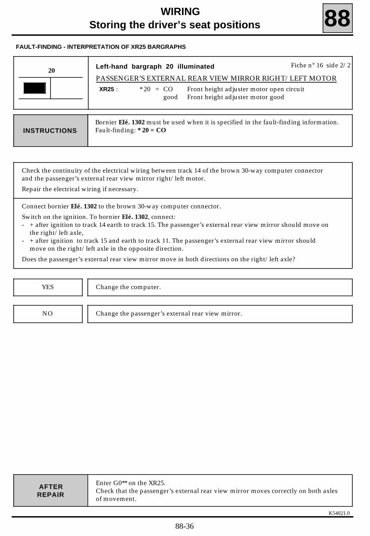
K54021.0
WIRINGStoring the driver’s seat positions 88
FAULT-FINDING - INTERPRETATION OF XR25 BARGRAPHS
AFTERREPAIR
Left-hand bargraph 20 illuminated
PASSENGER’S EXTERNAL REAR VIEW MIRROR RIGHT/LEFT MOTORXR25 : * 20 = CO Front height adjuster motor open circuit
good Front height adjuster motor good
20Fiche n° 16 side 2/2
Bornier Elé. 1302 must be used when it is specified in the fault-finding information.Fault-finding: * 20 = COINSTRUCTIONS
Enter G0** on the XR25.Check that the passenger’s external rear view mirror moves correctly on both axlesof movement.
Check the continuity of the electrical wiring between track 14 of the brown 30-way computer connectorand the passenger’s external rear view mirror right/left motor.
Repair the electrical wiring if necessary.
Connect bornier Elé. 1302 to the brown 30-way computer connector.
Switch on the ignition. To bornier Elé. 1302, connect:- + after ignition to track 14 earth to track 15. The passenger’s external rear view mirror should move on
the right/left axle,- + after ignition to track 15 and earth to track 11. The passenger’s external rear view mirror should
move on the right/left axle in the opposite direction.
Does the passenger’s external rear view mirror move in both directions on the right/left axle?
Change the computer.YES
Change the passenger’s external rear view mirror.NO
88-36

K54021.0
WIRINGStoring the driver’s seat positions 88
FAULT-FINDING - INTERPRETATION OF XR25 BARGRAPHS
AFTERREPAIR
Right-hand bargraph 20 illuminated
PASSENGER’S EXTERNAL REAR VIEW MIRROR RIGHT/LEFT SENSORCIRCUIT
20Fiche n° 16 side 2/2
Bornier Elé. 1302 must be used when it is specified in the fault-finding information.INSTRUCTIONS
Enter G0** on the XR25. Check that the passenger’s external rear view mirrormoves correctly on both axles of movement. Check that the passenger’s externalrear view mirror returns to its stored position during automatic operation.
Connect bornier Elé. 1302 in parallel to the brown 30-way computer connector.With the ignition on, measure the voltage between tracks 16 and 18 of bornier Elé. 1302. The voltageshould be ~ 5 volts.If the voltage is not ~ 5 volts, change the computer.
Check the continuity and the absence of short circuits to earth on the electrical wiring between thebrown 30-way computer connector tracks:- 10- 16 and the passenger’s external rear view mirror- 18Repair the electrical wiring if necessary.
With the ignition on, check that the voltage measured between tracks 10 and 18 of the brown 30-waycomputer connector varies between ~0 volts and ~5 volts by operating the passenger’s external rearview mirror right/left control.Does the voltage vary between these values?
Change the computer.YES
Change the passenger’s external rear view mirror.NO
88-37

K54021.0
WIRINGStoring the driver’s seat positions 88
Left-hand bargraph 2 extinguished, ignition on
+ AFTER IGNITION SUPPLY CIRCUITXR25 : * 03 = CO Position motor open circuit
good Position motor good
2Fiche n° 16 side 1/2
FAULT-FINDING - INTERPRETATION OF XR25 BARGRAPHS
With the ignition on, left-hand bargraph 2 should be illuminated on fiche n ° 16side 1/2.INSTRUCTIONS
Check that left-hand bargraph 2 is illuminated on fiche n°16 side 1/2 when theignition is on.
AFTERREPAIR
Check the condition of the 25 A "Sun roof/heated seats" fuse on the passenger compartment fuse board.
Change the fuse if it has blown.
With the ignition on, check the presence of ~ 12 volts on track A1 of the black 15-way computerconnector.
Is ~ 12 volts present?
Change the computer.YES
Repair the electrical wiring between track A1 of the black 15-way computerconnector and the passenger compartment fuse box.
NO
88-38

K54021.0
WIRING
Storing the driver’s seat positions 88
Left-hand bargraph 7 and left-hand bargraph 9 or
right-hand bargraph 9 extinguished, driver’s external rear viewmirror up or down control operated
DRIVER’S EXTERNAL REAR VIEW MIRROR UP/DOWN CONTROLCIRCUIT
7 Fiche n° 16 side 1/2
FAULT-FINDING - INTERPRETATION OF XR25 BARGRAPHS
Only refer to this status bargraph after checking that there are no fault bargraphson the XR25INSTRUCTIONS
Enter G0** on the XR25.AFTERREPAIR
9
Disconnect the electric external rear view mirror control connector on the armrest on the driver’s side.
With the ignition on, to the connector previously disconnected (connector wiring end), using a wireconnect the following tracks to each other:- A2 and A3: left-hand bargraph 7 and left-hand bargraph 9 should be illuminated,- A3 and B3 : left-hand bargraph 7 and right-hand bargraph 9 should be illuminated.
Are these bargraphs illuminated?
NO
YES Change the electric external rear view mirror control.
Check the continuity of the electrical wiring between track A3 of the electricexternal rear view mirror control and track 4 of the 30-way computer connector.
Is the electrical wiring in good condition?
YES Change the computer.
NO Repair the electrical wiring.
88-39

K54021.0
WIRING
Storing the driver’s seat positions 88FAULT-FINDING - INTERPRETATION OF XR25 BARGRAPHS
AFTERREPAIR
Left-hand bargraph 7 and left-hand bargraph 10 or
right-hand bargraph 10 extinguished, driver’s external rear viewmirror left or right control operated
DRIVER’S EXTERNAL REAR VIEW MIRROR LEFT/RIGHT CONTROLCIRCUIT
7 Fiche n° 16 side 1/2
Only refer to this status bargraph after checking that there are no fault bargraphson the XR25INSTRUCTIONS
Enter G0** on the XR25.
10
Disconnect the electric external rear view mirror control connector on the armrest on the driver’s side.
With the ignition on, to the connector previously disconnected (connector wiring end), using a wireconnect the following tracks to each other:- A1 and A2 : left-hand bargraph 7 and left-hand bargraph 10 should be illuminated,- A1 and B3 : left-hand bargraph 7 and right-hand bargraph 10 should be illuminated.
Are these bargraphs illuminated?
NO
YES Change the electric external rear view mirror control.
Check the continuity of the electrical wiring between track A1 of the electricexternal rear view mirror control and track 2 of the 30-way computer connector.
Is the electrical wiring in good condition?
YES Change the computer.
NO Repair the electrical wiring.
88-40

K54021.0
WIRINGStoring the driver’s seat positions 88
Right-hand bargraph 7 and left-hand bargraph 9 or
right-hand bargraph 9 extinguished, passenger’s external mirror upor down control operated
PASSENGER’S EXTERNAL REAR VIEW MIRROR UP/DOWN CONTROLCIRCUIT
7 Fiche n° 16 side 1/2
FAULT-FINDING - INTERPRETATION OF XR25 BARGRAPHS
Only refer to this status bargraph after checking that there are no fault bargraphson the XR25INSTRUCTIONS
Enter G0** on the XR25.AFTERREPAIR
9
Disconnect the electric external rear view mirror control connector on the armrest on the driver’s side.
With the ignition on, to the connector previously disconnected (connector wiring end), using a wireconnect the following tracks to each other:- A2 and B2 : right-hand bargraph 7 and left-hand bargraph 9 should be illuminated,- B2 and B3 : right-hand bargraph 7 and right-hand bargraph 9 should be illuminated.
Are these bargraphs illuminated?
NO
YES Change the electric external rear view mirror control.
Check the continuity of the electrical wiring between track B2 of the electric doormirror control and track 3 of the 30-way computer connector.
Is the electrical wiring in good condition?
YES Change the computer.
NO Repair the electrical wiring.
88-41

K54021.0
WIRING
Storing the driver’s seat positions 88FAULT-FINDING - INTERPRETATION OF XR25 BARGRAPHS
AFTERREPAIR
Right-hand bargraph 7 and left-hand bargraph 10 orright-hand bargraph 10 extinguished, passenger’s external rearview mirror left or right control operated
PASSENGER’S EXTERNAL REAR VIEW MIRROR LEFT/RIGHT CONTROLCIRCUIT
7 Fiche n° 16 side 1/2
Only refer to this status bargraph after checking that there are no fault bargraphson the XR25INSTRUCTIONS
Enter G0** on the XR25.
10
Disconnect the electric external rear view mirror control connector on the armrest on the driver’s side.
With the ignition on, to the connector previously disconnected (connector wiring end), using a wireconnect the following tracks to each other:- A2 and B1 : right-hand bargraph 7 and left-hand bargraph 10 should be illuminated,- B1 and B3 : right-hand bargraph 7 and right-hand bargraph 10 should be illuminated.
Are these bargraphs illuminated?
NO
YES Change the electric external rear view mirror control.
Check the continuity of the electrical wiring between track B1 of the electric doormirror control and track 1 of the 30-way computer connector.
is the electrical wiring in good condition?
YES Change the computer.
NO Repair the electrical wiring.
88-42

Left-hand bargraph 11, incorrect illumination
FORWARDS POSITION CONTROL CIRCUIT
XR25 : Left-hand bargraph 11 remains extinguished, forwards positioncontrol operated ---> Section 1Left-hand bargraph 11 illuminated, forwards position control at rest
---> Section 2
K54021.0
WIRING
Storing the driver’s seat positions 88
Enter G0** on the XR25.Check that the manual control pad operates correctly.
AFTERREPAIR
11Fiche n° 16 side 1/2
FAULT-FINDING - INTERPRETATION OF XR25 BARGRAPHS
Only refer to this status bargraph after checking that there are no fault bargraphson the XR25INSTRUCTIONS
SECTION 1During normal operation, left-hand bargraph 11 isextinguished if the forwards position control is at restINSTRUCTIONS
Connect bornier Elé. 1302 in parallel to the green 15-way computer connector.
Connect tracks 9 and 14 of bornier Elé. 1302. Left-hand bargraph 11 should be illuminated.
Is left-hand bargraph 11 illuminated?
Change the computer.NO
YES Disconnect the manual control pad connector.Operate the forwards position control and measure the resistance betweentracks A3 and B1 of the manual control pad.The resistance should be : R ≈ 0 ohm
Is the resistance R ≈ 0 ohm ?
YES Repair the faulty electrical wiring between:
manual control A3 and 14 green 15-waypad B1 9 computer connector
NO Change the manual control pad.
88-43

K54021.0
WIRINGStoring the driver’s seat positions 88
Enter G0** on the XR25.Check that the manual control pad operates correctly.
AFTERREPAIR
11
FAULT-FINDING - INTERPRETATION OF XR25 BARGRAPHS
CONT
SECTION 2During normal operation, left-hand bargraph 11 isilluminated if the forwards position control is operatedINSTRUCTIONS
Disconnect the manual control pad connector.
Left-hand bargraph 11 should extinguish.
Is left-hand bargraph 11 extinguished?
NO
YES Change the manual control pad.
Check that there are no short circuits on the electrical wiring between track 14 ofthe green 15-way computer connector and track A3 of the manual control pad.
Is the electrical wiring in good condition?
YES Change the computer.
NO Repair the electrical wiring.
88-44

K54021.0
WIRINGStoring the driver’s seat positions 88
Enter G0** on the XR25.Check that the manual control pad operates correctly.
AFTERREPAIR
Right-hand bargraph 11, incorrect illumination
BACKWARDS POSITION CONTROL CIRCUIT
XR25 : Right-hand bargraph 11 remains extinguished, backwards positioncontrol operated ---> Section 1Right-hand bargraph 11 illuminated, backwards position control atrest ---> Section 2
11Fiche n° 16 side 1/2
FAULT-FINDING - INTERPRETATION OF XR25 BARGRAPHS
Only refer to this status bargraph after checking that there are no fault bargraphson the XR25INSTRUCTIONS
SECTION 1During normal operation, right-hand bargraph 11 isextinguished if the backwards position control is at restINSTRUCTIONS
Connect bornier Elé. 1302 in parallel to the green 15-way computer connector.Connect tracks 14 and 8 of bornier Elé. 1302. Right-hand bargraph 11 should be illuminated.Is right-hand bargraph 11 illuminated?
Change the computer.NO
YES Disconnect the manual control pad connector.Operate the backwards position control and measure the resistance betweentracks A3 and B6 of the manual control pad.The resistance should be: R ≈ 0 ohm
Is the resistance R ≈ 0 ohm ?
YES Repair the faulty electrical wiring between:
manual control A3 and14 green 15-waypad B6 8 computer connector
NO Change the manual control pad.
88-45

K54021.0
WIRINGStoring the driver’s seat positions 88
Enter G0** on the XR25.Check that the manual control pad operates correctly.
AFTERREPAIR
11
FAULT-FINDING - INTERPRETATION OF XR25 BARGRAPHS
CONT
SECTION 2During normal operation right-hand bargraph 11 isilluminated if the backwards position control is operated.INSTRUCTIONS
Disconnect the manual control pad connector.
Right-hand bargraph 11 should extinguish.
Is right-hand bargraph 11 extinguished?
NO
YES Change the manual control pad.
Check that there are no short circuits on the electrical wiring between track 14 ofthe green 15-way computer connector and track A3 of the manual control pad.
Is the electrical wiring in good condition?
YES Change the computer.
NO Repair the electrical wiring.
88-46
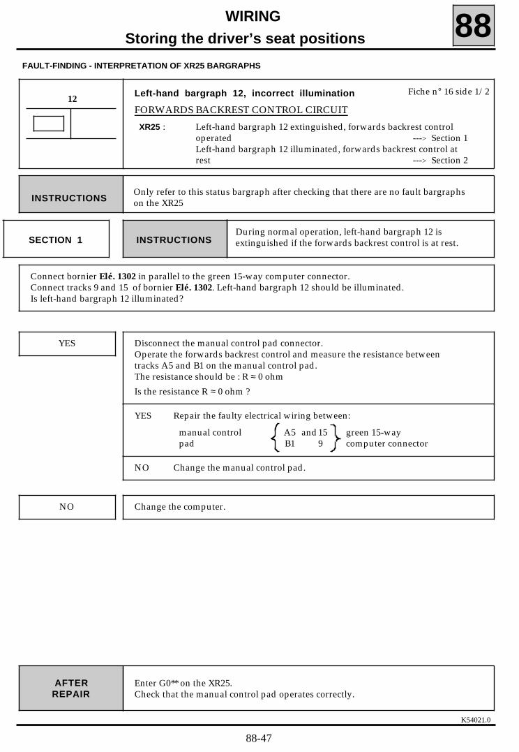
K54021.0
WIRING
Storing the driver’s seat positions 88
Enter G0** on the XR25.Check that the manual control pad operates correctly.
AFTERREPAIR
Left-hand bargraph 12, incorrect illumination
FORWARDS BACKREST CONTROL CIRCUIT
XR25 : Left-hand bargraph 12 extinguished, forwards backrest controloperated ---> Section 1Left-hand bargraph 12 illuminated, forwards backrest control atrest ---> Section 2
12Fiche n° 16 side 1/2
FAULT-FINDING - INTERPRETATION OF XR25 BARGRAPHS
Only refer to this status bargraph after checking that there are no fault bargraphson the XR25INSTRUCTIONS
SECTION 1During normal operation, left-hand bargraph 12 isextinguished if the forwards backrest control is at rest.INSTRUCTIONS
Connect bornier Elé. 1302 in parallel to the green 15-way computer connector.Connect tracks 9 and 15 of bornier Elé. 1302. Left-hand bargraph 12 should be illuminated.Is left-hand bargraph 12 illuminated?
Change the computer.NO
YES Disconnect the manual control pad connector.Operate the forwards backrest control and measure the resistance betweentracks A5 and B1 on the manual control pad.The resistance should be : R ≈ 0 ohm
Is the resistance R ≈ 0 ohm ?
YES Repair the faulty electrical wiring between:
manual control A5 and15 green 15-waypad B1 9 computer connector
NO Change the manual control pad.
88-47
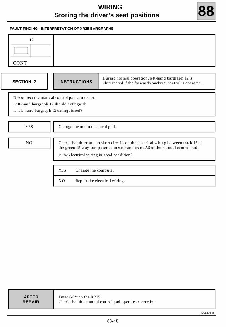
K54021.0
WIRINGStoring the driver’s seat positions 88
Enter G0** on the XR25.Check that the manual control pad operates correctly.
AFTERREPAIR
12
FAULT-FINDING - INTERPRETATION OF XR25 BARGRAPHS
CONT
SECTION 2During normal operation, left-hand bargraph 12 isilluminated if the forwards backrest control is operated.INSTRUCTIONS
Disconnect the manual control pad connector.
Left-hand bargraph 12 should extinguish.
Is left-hand bargraph 12 extinguished?
NO
YES Change the manual control pad.
Check that there are no short circuits on the electrical wiring between track 15 ofthe green 15-way computer connector and track A5 of the manual control pad.
is the electrical wiring in good condition?
YES Change the computer.
NO Repair the electrical wiring.
88-48

K54021.0
WIRINGStoring the driver’s seat positions 88
Enter G0** on the XR25.Check that the manual control pad operates correctly.
AFTERREPAIR
Right-hand bargraph 12, incorrect illumination
BACKWARDS BACKREST CONTROL CIRCUIT
XR25 : Right-hand bargraph 12 remains extinguished, backwards backrestcontrol operated ---> Section 1Right-hand bargraph 12 illuminated, backwards backrest control atrest ---> Section 2
12Fiche n° 16 side 1/2
FAULT-FINDING - INTERPRETATION OF XR25 BARGRAPHS
Only refer to this status bargraph after checking that there are no fault bargraphson the XR25INSTRUCTIONS
SECTION 1During normal operation, right-hand bargraph 12 isextinguished if the backwards backrest control is at restINSTRUCTIONS
Connect bornier Elé. 1302 in parallel to the green 15-way computer connector.Connect tracks 8 and 15 of bornier Elé. 1302. Right-hand bargraph 12 should be illuminated.
Is right-hand bargraph 12 illuminated?
Change the computer.NO
YES Disconnect the manual control pad.Operate the backwards backrest control and measure the resistance betweentracks A5 and B6 of the manual control pad.The resistance should be : R ≈ 0 ohm
Is the resistance R ≈ 0 ohm ?
YES Repair the faulty electrical wiring between:
manual control A5 and green 15-waypad B6 8 computer connector
NO Change the manual control pad.
88-49

K54021.0
WIRINGStoring the driver’s seat positions 88
Enter G0** on the XR25.Check that the manual control pad operates correctly.
AFTERREPAIR
12
FAULT-FINDING - INTERPRETATION OF XR25 BARGRAPHS
CONT
SECTION 2During normal operation, right-hand bargraph 12 isilluminated if the backwards backrest control is operated.INSTRUCTIONS
Disconnect the manual control pad connector.
Right-hand bargraph 12 should extinguish.
Is right-hand bargraph 12 extinguished?
NO
YES Change the manual control pad.
Check that there are no short circuits on the electrical wiring between track 15 ofthe green 15-way computer connector and track A5 of the manual control pad.
Is the electrical wiring in good condition?
YES Change the computer.
NO Repair the electrical wiring.
88-50

K54021.0
WIRINGStoring the driver’s seat positions 88
Enter G0** on the XR25.Check that the manual control pad operates correctly.
AFTERREPAIR
Left-hand bargraph 13, incorrect illumination
UPWARDS REAR HEIGHT ADJUSTER CONTROL CIRCUIT
XR25 : Left-hand bargraph 13 remains extinguished, upwards rear heightadjuster operated ---> Section 1Left-hand bargraph 13 illuminated, upwards rear height adjuster atrest ---> Section
13Fiche n° 16 side 1/2
FAULT-FINDING - INTERPRETATION OF XR25 BARGRAPHS
Only refer to this status bargraph after checking that there are no fault bargraphson the XR25INSTRUCTIONS
SECTION 1During normal operation, left-hand bargraph 13 isextinguished if the upwards rear height adjuster control isoperated
INSTRUCTIONS
Connect bornier Elé. 1302 in parallel to the green 15-way computer connector.Connect tracks 9 and 12 of bornier Elé. 1302. Left-hand bargraph 13 should be illuminated.
Is left-hand bargraph 13 illuminated?
Change the computer.NO
YES Disconnect the manual control pad connector.Operate the upwards rear height adjuster control and measure the resistancebetween tracks A4 and B1 of the manual control pad.The resistance should be : R ≈ 0 ohm
Is the resistance R ≈ 0 ohm ?
YES Repair the faulty electrical wiring between:
Manual control A4 and12 green 15-way pad B1 9 computer connector
NO Change the manual control pad.
88-51

K54021.0
WIRING
Storing the driver’s seat positions 88
Enter G0** on the XR25.Check that the manual control pad operates correctly.
AFTERREPAIR
13
FAULT-FINDING - INTERPRETATION OF XR25 BARGRAPHS
CONT
SECTION 2During normal operation left-hand bargraph 13 isilluminated if the upwards rear height adjuster control isoperated
INSTRUCTIONS
Disconnect the manual control pad connector.
Left-hand bargraph 13 should extinguish.
Is left-hand bargraph 13 extinguished?
NO
YES Change the manual control pad.
Check that there are no short circuits on the electrical wiring between track 12 ofthe green 15-way computer connector and track A4 of the manual control pad.
Is the electrical wiring in good condition?
YES Change the computer.
NO Repair the electrical wiring.
88-52

K54021.0
WIRING
Storing the driver’s seat positions 88
Enter G0** on the XR25.Check that the manual control pad operates correctly.
AFTERREPAIR
Right-hand bargraph 13, incorrect illumination
DOWNWARDS REAR HEIGHT ADJUSTER CONTROL CIRCUIT
XR25 : Right-hand bargraph 13 remains extinguished, downwards rearheight adjuster control operated ---> Section 1Right-hand bargraph 13 illuminated, downwards rear heightadjuster control at rest ---> Section 2
13Fiche n° 16 side 1/2
FAULT-FINDING - INTERPRETATION OF XR25 BARGRAPHS
Only refer to this status bargraph after checking that there are no fault bargraphson the XR25INSTRUCTIONS
SECTION 1During normal operation, right-hand bargraph 13 isextinguished if the downwards rear height adjuster controlis at rest
INSTRUCTIONS
Connect bornier Elé. 1302 in parallel to the green 15-way computer connector.Connect tracks 8 and 12 of bornier Elé. 1302. Right-hand bargraph 13 should be illuminated.
Is right-hand bargraph 13 illuminated?
Change the computer.NO
YES Disconnect the manual control pad connector.Operate the downwards rear height adjuster control control and measure theresistance between tracks A4 and B6 of the manual control pad.The resistance should be : R ≈ 0 ohm
Is the resistance R ≈ 0 ohm ?
YES Repair the faulty electrical wiring between:
manual control A4 and12 green 15-way pad B6 8 computer connector
NO Change the manual control pad.
88-53

K54021.0
WIRINGStoring the driver’s seat positions 88
Enter G0** on the XR25.Check that the manual control pad operates correctly.
AFTERREPAIR
13
FAULT-FINDING - INTERPRETATION OF XR25 BARGRAPHS
CONT
SECTION 2During normal operation, right-hand bargraph 13 isilluminated if the downwards rear height adjuster controlis operated.
INSTRUCTIONS
Disconnect the manual control pad connector.
Right-hand bargraph 13 should extinguish.
Is right-hand bargraph 13 extinguished?
NO
YES Change the manual control pad.
Check that there are no short circuits on the electrical wiring between track 12 ofthe green 15-way computer connector and track A4 of the manual control pad.
Is the electrical wiring in good condition?
YES Change the computer.
NO Repair the electrical wiring.
88-54

K54021.0
WIRINGStoring the driver’s seat positions 88
Enter G0** on the XR25.Check that the manual control pad operates correctly.
AFTERREPAIR
Left-hand bargraph 14, incorrect illumination
UPWARDS FRONT HEIGHT ADJUSTER CONTROL CIRCUIT
XR25 : Left-hand bargraph 14 remains extinguished, upwards front heightadjuster control operated ---> Section 1Left-hand bargraph 14 illuminated, upwards front height adjusterat rest ---> Section 2
14Fiche n° 16 side 1/2
FAULT-FINDING - INTERPRETATION OF XR25 BARGRAPHS
Only refer to this status bargraph after checking that there are no fault bargraphson the XR25INSTRUCTIONS
SECTION 1During normal operation, left-hand bargraph 14 isextinguished if the upwards front height adjuster control isat rest
INSTRUCTIONS
Connect bornier Elé. 1302 in parallel to the green 15-way computer connector.Connect tracks 9 and 13 of bornier Elé. 1302. Left-hand bargraph 14 should be illuminated.Is left-hand bargraph 14 illuminated?
Change the computer.NO
YES Disconnect the manual control pad connector.Operate the upwards front height adjuster control and measure the resistancebetween tracks A1 and B1 of the manual control pad.The resistance should be: R ≈ 0 ohm
Is the resistance R ≈ 0 ohm ?
YES Repair the faulty electrical wiring between:
manual control A1 and13 green 15-waypad B1 9 computer connector
NO Change the manual control pad.
88-55

K54021.0
WIRINGStoring the driver’s seat positions 88
Enter G0** on the XR25.Check that the manual control pad operates correctly.
AFTERREPAIR
14
FAULT-FINDING - INTERPRETATION OF XR25 BARGRAPHS
CONT
SECTION 2During normal operation, left-hand bargraph 14 isilluminated if the upwards front height adjuster control isoperated
INSTRUCTIONS
Disconnect the manual control pad connector.
Left-hand bargraph 14 should extinguish.
Is left-hand bargraph 14 extinguished?
NO
YES Change the manual control pad.
Check that there are no short circuits on the electrical wiring between track 13 ofthe green 15-way computer connector and track A1 of the manual control pad.
Is the electrical wiring in good condition?
YES Change the computer.
NO Repair the electrical wiring.
88-56

K54021.0
WIRINGStoring the driver’s seat positions 88
Enter G0** on the XR25.Check that the manual control pad is operating correctly.
AFTERREPAIR
Right-hand bargraph 14, incorrect illumination
DOWNWARDS FRONT HEIGHT ADJUSTER CONTROL CIRCUIT
XR25 : Right-hand bargraph 14 remains extinguished, downwards frontheight adjuster control operated ---> Section 1Right-hand bargraph 14 illuminated, downwards front heightadjuster control at rest ---> Section 2
14Fiche n° 16 side 1/2
FAULT-FINDING - INTERPRETATION OF XR25 BARGRAPHS
Only refer to this status bargraph after checking that there are no fault bargraphson the XR25INSTRUCTIONS
SECTION 1During normal operation, right-hand bargraph 14 isextinguished if the downwards front height adjustercontrol is at rest.
INSTRUCTIONS
Connect bornier Elé. 1302 in parallel to the green 15-way computer connector.Connect tracks 8 and 13 of bornier Elé. 1302. Right-hand bargraph 14 should be illuminated.Is right-hand bargraph 14 illuminated?
Change the computer.NO
YES Disconnect the manual control pad.Operate the downwards front height adjuster control and measure theresistance between tracks A1 and B6 of the manual control pad.The resistance should be: R ≈ 0 ohm
Is the resistance R ≈ 0 ohm ?
YES Repair the faulty electrical wiring between:
manual control A1 and13 green 15-waypad B6 8 computer connector
NO Change the manual control pad.
88-57

K54021.0
WIRINGStoring the driver’s seat positions 88
Enter G0** on the XR25.Check that the manual control pad operates correctly.
AFTERREPAIR
14
FAULT-FINDING - INTERPRETATION OF XR25 BARGRAPHS
CONT
SECTION 2During normal operation, right-hand bargraph 14 isilluminated if the downwards front height adjuster isoperated
INSTRUCTIONS
Disconnect the manual control pad.
Right-hand bargraph 14 should extinguish.
Is right-hand bargraph 14 extinguished?
NO
YES Change the manual control pad.
Check that there are no short circuits on the electrical wiring between track 13 ofthe green 15-way computer connector and track A1 of the manual control pad.
Is the electrical wiring in good condition?
YES Change the computer.
NO Repair the electrical wiring.
88-58

K54021.0
WIRINGStoring the driver’s seat positions 88
Enter G0** on the XR25.Check that selection button "1" operates correctly.
AFTERREPAIR
Left-hand bargraph 17, incorrect illumination
SELECTION BUTTON "1" CIRCUIT
XR25 : Left-hand bargraph 17 extinguished, selection button "1" pressed
---> Section 1Left-hand bargraph 17 illuminated, selection button "1" released
---> Section 2
17Fiche n° 16 side 1/2
FAULT-FINDING - INTERPRETATION OF XR25 BARGRAPHS
Only refer to this status bargraph after checking that there are no fault bargraphson the XR25INSTRUCTIONS
SECTION 1During normal operation, left-hand bargraph 17 isextinguished if selection button "1" is releasedINSTRUCTIONS
Check that on fiche n° 16 side 1/2 :- left-hand bargraph 18 is illuminated when selection button "2" is pressed,- left-hand bargraph 19 is illuminated when selection button "3" is pressed.
Are left-hand bargraphs 18 and 19 illuminated?
Check the continuity of the electrical wiring between track A5 of the automaticcontrol pad and track 10 of the green 15-way computer connector.
Repair the electrical wiring.
NO
YES Check the continuity of the electrical wiring between track B5 of the automaticcontrol pad and track A5 of the manual control pad.
Repair the electrical wiring if necessary.
Using a multimeter, measure the resistance between tracks A5 and B5 of theautomatic control pad.The resistance should be :- R infinity selection button "1" released,- R < 80 Ω selection button "1" pressed.
Are the resistances correct?
If the resistances are correct, change the computer.
If the resistances are not correct, change the automatic control pad.
88-59

K54021.0
WIRINGStoring the driver’s seat positions 88
Enter G0** on the XR25.Check that selection button "1" is operating correctly.
AFTERREPAIR
17
FAULT-FINDING - INTERPRETATION OF XR25 BARGRAPHS
CONT
SECTION 2During normal operation, left-hand bargraph 17 isilluminated if selection button "1" is pressedINSTRUCTIONS
With the ignition on, disconnect the control pad and check whether left-hand bargraph 17 extinguishes.
If left-hand bargraph 17 extinguishes, change the automatic control pad.
NO
YES Change the computer.
Repair the electrical wiring.
Check that there are no short circuits on the electrical wiring between track B5 of the automatic controlpad and track 15 of the green 15-way computer connector.
Is the electrical wiring in good condition?
88-60

K54021.0
WIRINGStoring the driver’s seat positions 88
Enter G0** on the XR25.Check that selection button "2" operates correctly.
AFTERREPAIR
Left-hand bargraph 18, incorrect illumination
SELECTION BUTTON "2" CIRCUIT
XR25 : Left-hand bargraph 18 extinguished, selection button "2" pressed
---> Section 1Left-hand bargraph 18 illuminated, selection button "2" released
---> Section 2
18Fiche n° 16 side 1/2
FAULT-FINDING - INTERPRETATION OF XR25 BARGRAPHS
Only refer to this status bargraph after checking that there are no fault bargraphson the XR25INSTRUCTIONS
SECTION 1During normal operation, left-hand bargraph 18 isextinguished is selection button "2" is releasedINSTRUCTIONS
Check that on fiche n° 16 side 1/2 :- left-hand bargraph 17 is illuminated when selection button "1" is pressed,- left-hand bargraph 19 is illuminated when selection button "3" is pressed.
Are left-hand bargraphs 17 and 19 illuminated?
Check the continuity of the electrical wiring between track A5 of the automaticcontrol pad and track 10 of the green 15-way computer connector.
Repair the electrical wiring.
NO
YES Check the continuity of the electrical wiring between track B4 of the automaticcontrol pad and track A3 of the manual control pad.
Repair the electrical wiring if necessary.
Using a multimeter, measure the resistance between tracks B4 and A5 of theautomatic control pad.
The resistance should be:- R infinity selection button "2" released,- R < 80 Ω selection button "2" pressed.
Are the resistances correct?
If the resistances are correct, change the computer.
If the resistances are not correct, change the automatic control pad.
88-61

K54021.0
WIRINGStoring the driver’s seat positions 88
Enter G0** on the XR25.Check that selection button "2" is operating correctly.
AFTERREPAIR
18
FAULT-FINDING - INTERPRETATION OF XR25 BARGRAPHS
CONT
SECTION 2During normal operation, left-hand bargraph 18 isilluminated if selection button "2" is pressedINSTRUCTIONS
With the ignition on, disconnect the control pad and check whether left-hand bargraph 18 extinguishes.
If left-hand bargraph 18 extinguishes, change the automatic control pad.
NO
YES Change the computer.
Repair the electrical wiring.
Check that there are no short circuits on the electrical wiring between track B4 of the automatic controlpad and track 14 of the green 15-way computer connector.
Is the electrical wiring in good condition?
88-62

K54021.0
WIRINGStoring the driver’s seat positions 88
Enter G0** on the XR25.Check that selection button "3" operates correctly.
AFTERREPAIR
FAULT-FINDING - INTERPRETATION OF XR25 BARGRAPHS
Left-hand bargraph 19, incorrect illumination
SELECTION BUTTON "3" CIRCUIT
XR25 : Left-hand bargraph 19 extinguished, selection button "3" pressed
---> Section 1Left-hand bargraph 19 illuminated, selection button "3" released
---> Section 2
19Fiche n° 16 side 1/2
Only refer to this status bargraph after checking that there are no fault bargraphson the XR25INSTRUCTIONS
SECTION 1During normal operation, left-hand bargraph 19 isextinguished if selection button "3" is releasedINSTRUCTIONS
Check that on fiche n° 16 side 1/2 :- left-hand bargraph 17 is illuminated when selection button "1" is pressed,- left-hand bargraph 18 is illuminated when selection button "2" is pressed.
Are left-hand bargraphs 17 and 18 illuminated?
Check the continuity of the electrical wiring between track A5 of the automaticcontrol pad and track 10 of the green 15-way computer connector.
Repair the electrical wiring.
NO
YES Check the continuity of the electrical wiring between track B3 of the automaticcontrol pad and track A1 of the manual control pad.
Repair the electrical wiring if necessary.
Using a multimeter, measure the resistance between tracks B3 and A5 of theautomatic control pad.
The resistances should be:- R infinity selection button "3" released,- R < 80 Ω selection button "3" pressed.
Are the resistances correct?
If the resistances are correct, change the computer.
If the resistances are not correct, change the automatic control pad.
88-63

K54021.0
WIRING
Storing the driver’s seat positions 88
Enter G0** on the XR25.Check that selection button "3" operates correctly.
AFTERREPAIR
19
FAULT-FINDING - INTERPRETATION OF XR25 BARGRAPHS
CONT
SECTION 2During normal operation, left-hand bargraph 19 isilluminated if selection button "3" is pressedINSTRUCTIONS
With the ignition on, disconnect the control pad and check whether left-hand bargraph 19 extinguishes.
If left-hand bargraph 19 extinguishes, change the automatic control pad.
NO
YES Change the computer.
Repair the electrical wiring.
Check that there are no short circuits on the electrical wiring between track B3 of the automatic controlpad and track 13 of the green 15-way computer connector.
Is the electrical wiring in good condition?
88-64

K54021.0
WIRINGStoring the driver’s seat positions 88
Enter G0** on the XR25.Check that the "STORE" button operates correctly.
AFTERREPAIR
Right-hand bargraphs 17, 18 and 19, incorrect illumination
"STORE" BUTTON CIRCUIT
XR25 : Right-hand bargraphs 17, 18 and 19 extinguished, "STORE" buttonpressed ---> Section 1Right-hand bargraphs 17,18 and 19 illuminated, "STORE" buttonreleased ---> Section 2
17 - 18 - 19Fiche n° 16 side 1/2
FAULT-FINDING - INTERPRETATION OF XR25 BARGRAPHS
Only refer to this status bargraph after checking that there are no fault bargraphson the XR25INSTRUCTIONS
SECTION 1During normal operation, right-hand bargraphs 17, 18 and19 are extinguished if the "STORE" button is releasedINSTRUCTIONS
Check that on fiche n° 16 side 1/2 :- left-hand bargraph 17 is illuminated when selection button "1" is pressed,- left-hand bargraph 18 is illuminated when selection button "2" is pressed,- left-hand bargraph 19 is illuminated when selection button "3" is pressed,
Do left-hand bargraphs 17, 18 and 19 illuminate?
Check the continuity of the electrical wiring between the automatic control padtrack:- A4 and track B4 of the manual control pad- A5 and track 10 of the green 15-way computer connector..
NO
YES Check the continuity of the electrical wiring between track A4 of the automaticcontrol pad and track B4 of the manual control pad.
Repair the electrical wiring if necessary.
Using a multimeter, measure the resistance between tracks A4 and A5 of theautomatic control pad.
The resistance should be R < 80 Ω "STORE" button pressed.
Is the resistance R < 80 Ω ?
If the resistance is R < 80 Ω, change the computer.
If the resistance is not R < 80 Ω, change the automatic control pad..
88-65

K54021.0
WIRINGStoring the driver’s seat positions 88
Enter G0** on the XR25.Check that the "STORE" button operates correctly.
AFTERREPAIR
17 - 18 - 19
FAULT-FINDING - INTERPRETATION OF XR25 BARGRAPHS
CONT
SECTION 2During normal operation right-hand bargraphs 17, 18 and19 are illuminated if the "STORE" button is pressedINSTRUCTIONS
With the ignition on, disconnect the control pad and check whether right-hand bargraphs 17, 18 and 19extinguish.
If right-hand bargraphs 17, 18 and 19 extinguish, change the automatic control pad.
NO
YES Change the computer.
Repair the electrical wiring.
Check that there are no short circuit on the electrical wiring:
manual control A4 and 12 of the 15-way computer connectorpad B4 A4 of the automatic control pad
Is the electrical wiring in good condition?
88-66

K54021.0
WIRINGStoring the driver’s seat positions 88
FAULT-FINDING - CUSTOMER COMPLAINTS
CHART 2
Only refer to the study for this status bargraph after checking that there are nofault bargraphs on the XR25 and that the status bargraphs illuminate correctly.INSTRUCTIONS
OF THE SEAT
No seat control at all
No control of one movement
in one direction only
in both directions
CHART 3
CHART 4
NO COMMUNICATION BETWEEN THE XR25 AND THE COMPUTER
PROBLEM DURING MANUAL OPERATION
CHART 1
OF THE DRIVER’S EXTERNAL REAR VIEW MIRROR
No operation on the up/down axle
in one direction only
in both directions
CHART 5
CHART 6
No operation on the left/right axle
in one direction only
in both directions
CHART 7
CHART 8
OF THE PASSENGER’S EXTERNAL REAR VIEW MIRROR
No operation on the up/down axle
in one direction only
in both directions
CHART 9
CHART 10
No operation on the left/right axle
in one direction only
in both directions
CHART 11
CHART 12
88-67

K54021.0
WIRINGStoring the driver’s seat positions 88
FAULT-FINDING - CUSTOMER COMPLAINTS (cont)
CHART 13
CHART 15
OF BOTH EXTERNAL REAR VIEW MIRRORS
No operation of either movement (right/left and up/down)
No operation of one movement
PROBLEM DURING MANUAL OPERATION
GENERAL FAILURE OF ALL FUNCTIONS CHART 15
CHART 16
CHART 17
CHART 18
CHART 19
CHART 20
CHART 21
CHART 22
CHART 23
CHART 24
CHART 25
No memory recall on all 4 seat axles
No memory recall on one of the 4 seat axles
No memory recall on both external rear view mirrors
No recall on the driver’s external rear view mirror (on one or more movements)
No recall on the passenger’s external rear view mirror (on one or more movements)
No recall on the seat and external rear view mirrors functions
No recall on a stored position (1, 2 or 3)
A position cannot be stored
No movement of the passenger’s external rear view mirror glass when reverse gear isengaged
Recall of a stored position incorrect (one or more axles)
PROBLEM DURING AUTOMATIC OPERATION
88-68

K54021.0
WIRINGStoring the driver’s seat positions 88
FAULT-FINDING CHARTS
CHART 1 NO XR25/COMPUTER COMMUNICATION
None.INSTRUCTIONS
When communication is established, deal with any illuminated fault bargraphs.AFTERREPAIR
Before establishing communication between the XR25 and the computer, check the following condition- ignition on.
Check the condition of the 25 A "Seat memory" and 10 A "Clock" fuses.
Change the fuses if necessary.
Check that the XR25 is not the cause of the fault by trying to communicate with a computer on anothervehicle.
Check that the ISO interface is in position S8, that you are using the latest version of the XR25 cassetteand the correct access code (D16).
Check the battery voltage (U > 10.5 volts). Recharge the battery if necessary.
Check that the computer connectors are engaged correctly.
Check that the computer is supplied correctly:- earth on track B4 and B5 of the black 15-way computer connector,- + before ignition on track B1 of the black 15-way computer connector.
Check that the diagnostics socket is supplied correctly:- earth on track 5- + before ignition on track 16.
Check and repair the continuity and insulation of the electrical wiring between the diagnostics socketconnector and tracks:- 8 of the computer- 14
If there is still no dialogue between the XR25 and the computer, change the computer.
88-69
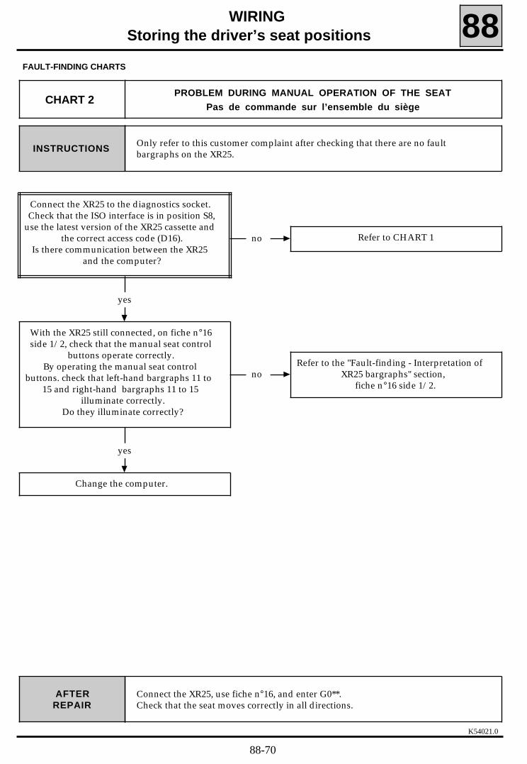
K54021.0
WIRINGStoring the driver’s seat positions 88
FAULT-FINDING CHARTS
Only refer to this customer complaint after checking that there are no faultbargraphs on the XR25.INSTRUCTIONS
CHART 2PROBLEM DURING MANUAL OPERATION OF THE SEAT
Pas de commande sur l’ensemble du siège
Connect the XR25, use fiche n°16, and enter G0**.Check that the seat moves correctly in all directions.
AFTERREPAIR
no Refer to CHART 1
yes
With the XR25 still connected, on fiche n°16side 1/2, check that the manual seat control
buttons operate correctly.By operating the manual seat control
buttons. check that left-hand bargraphs 11 to15 and right-hand bargraphs 11 to 15
illuminate correctly.Do they illuminate correctly?
Connect the XR25 to the diagnostics socket.Check that the ISO interface is in position S8,
use the latest version of the XR25 cassette andthe correct access code (D16).
Is there communication between the XR25and the computer?
yes
Change the computer.
noRefer to the "Fault-finding - Interpretation of
XR25 bargraphs" section,fiche n°16 side 1/2.
88-70

K54021.0
WIRINGStoring the driver’s seat positions 88
FAULT-FINDING CHARTS
Only refer to this customer complaint after checking that there are no faultbargraphs on the XR25.INSTRUCTIONS
Connect the XR25, use fiche n°16, and enter G0**.
Check that the seat moves correctly in all directions.
AFTERREPARATION
CHART 3PROBLEM DURING MANUAL OPERATION OF THE SEAT
No control of one movement in one direction
no Refer to the "Fault-finding - Interpretation ofXR25 bargraphs" section.
yes
Check the mechanical part of the seat(reduction gear, cables, ...).
Are these components on good condition?
Connect the XR25. Use fiche n°16 side 1/2.Check that the manual control pad operatescorrectly. Operate the manual control pad
and check the correct illumination of:- left and right-hand bargraph
11- left and right-hand bargraph
12- left and right-hand bargraph
13- left and right-hand bargraph
14Do these bargraphs illuminate correctly?
no Repair the faulty component.
yes
Change the computer.
88-71

K54021.0
WIRINGStoring the driver’s seat positions 88
FAULT-FINDING CHARTS
Only refer to this customer complaint after checking that there are no faultbargraphs on the XR25.INSTRUCTIONS
Connect the XR25, use fiche n°16, and enter G0**.
Check that the seat moves correctly in all directions.
AFTERREPAIR
CHART 4PROBLEM DURING MANUAL OPERATION OF THE SEAT
No control of a movement in both directions
no Refer to the "Fault-finding - Interpretation ofXR25 bargraphs" section.
yes
Change the computer.
Connect the XR25. Use fiche n°16 side 1/2.Check that the manual control pad operatescorrectly. Operate the manual control pad
and check the correct illumination of:- left and right-hand bargraph
11- left and right-hand bargraph
12- left and right-hand bargraph
13- left and right-hand bargraph
14Do these bargraphs illuminate correctly?
88-72

K54021.0
WIRINGStoring the driver’s seat positions 88
FAULT-FINDING CHARTS
Only refer to this customer complaint after checking that there are no faultbargraphs on the XR25.INSTRUCTIONS
Connect the XR25, use fiche n°16, and enter G0**.Check that the driver’s external rear view mirror moves correctly in all directions.AFTER
REPAIR
CHART 5PROBLEM DURING MANUAL OPERATION OF THE DRIVER’S EXTERNAL
REAR VIEW MIRRORNo operation on the up/down axle in one direction
no
Refer to the "Fault-finding - Interpretation ofXR25 bargraphs" section, study of left-handbargraph 7, left-hand bargraph 9 or right-
hand bargraph 9 extinguished, driver’sexternal rear view mirror up/down control
operated.
yes
yes Check that there is no mechanical blockage ofthe driver’s external rear view mirror.
no
yes
Change the computer.
Connect bornier Elé. 1302 to the brown 30-way computer connector. Switch on theignition. To bornier Elé. 1302, connect:
- + after ignition to track 12 and earth ontrack 15. The driver’s external rear viewmirror should move on the up/down axle.
- + after ignition on track 15 and earth ontrack 12. The driver’s external rear viewmirror should move on the up/down axlein the opposite direction.
Does the driver’s external rear view mirrormove on the up/down axle in both
directions?
Check whether the motor can be heardturning in the direction of non-operation ofthe driver’s external rear view mirror when
the control button is operated. Can the motorbe heard?
Connect the XR25. Use fiche n°16 side 1/2.Check that the external rear view mirrors
control button operates correctlyOperate the driver’s external rear view mirrorup/down control button and check whether:- up control operated: left-hand bargraphs
7 and 9 illuminated.- down control operated: left-hand
bargraph 7 and right-hand bargraph 9illuminated.
Do these bargraphs illuminate correctly?
no
yes no
Repair the faulty electrical wiring.
Change the driver’sexternal rear view
mirror.
Check the continuity and absence of shortcircuits to earth and to + 12 volts on the
electrical wiring between the brown 30-waycomputer connector:
- A12 and the driver’s external rearview mirror,
- A15 and the driver’s external rearview mirror.
Is the electrical wiring in good condition?
88-73
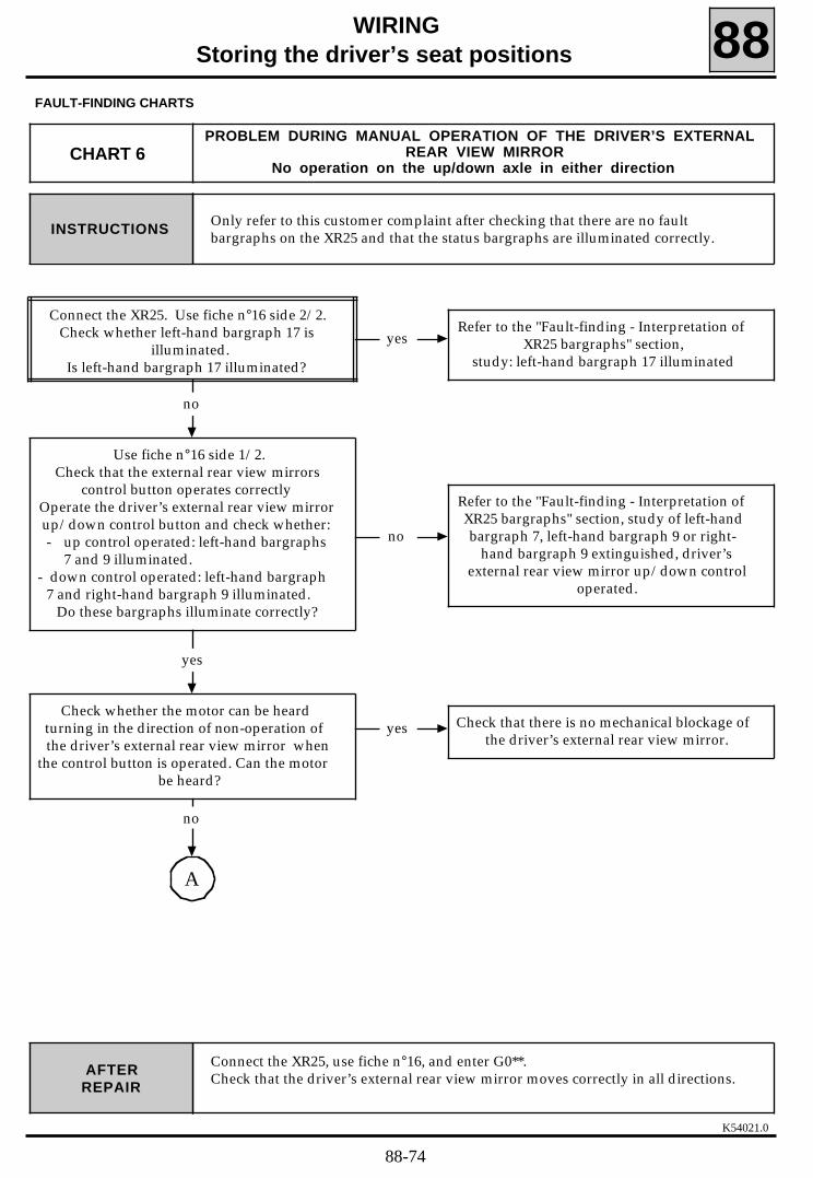
K54021.0
WIRINGStoring the driver’s seat positions 88
FAULT-FINDING CHARTS
Only refer to this customer complaint after checking that there are no faultbargraphs on the XR25 and that the status bargraphs are illuminated correctly.INSTRUCTIONS
Connect the XR25, use fiche n°16, and enter G0**.Check that the driver’s external rear view mirror moves correctly in all directions.AFTER
REPAIR
CHART 6PROBLEM DURING MANUAL OPERATION OF THE DRIVER’S EXTERNAL
REAR VIEW MIRRORNo operation on the up/down axle in either direction
yes
no
Refer to the "Fault-finding - Interpretation ofXR25 bargraphs" section, study of left-handbargraph 7, left-hand bargraph 9 or right-
hand bargraph 9 extinguished, driver’sexternal rear view mirror up/down control
operated.
yes
yes Check that there is no mechanical blockage ofthe driver’s external rear view mirror.
no
Connect the XR25. Use fiche n°16 side 2/2. Check whether left-hand bargraph 17 is
illuminated.Is left-hand bargraph 17 illuminated?
Refer to the "Fault-finding - Interpretation ofXR25 bargraphs" section,
study: left-hand bargraph 17 illuminated
A
no
Check whether the motor can be heardturning in the direction of non-operation ofthe driver’s external rear view mirror when
the control button is operated. Can the motorbe heard?
Use fiche n°16 side 1/2. Check that the external rear view mirrors
control button operates correctlyOperate the driver’s external rear view mirrorup/down control button and check whether:- up control operated: left-hand bargraphs
7 and 9 illuminated.- down control operated: left-hand bargraph
7 and right-hand bargraph 9 illuminated.Do these bargraphs illuminate correctly?
88-74

K54021.0
WIRINGStoring the driver’s seat positions 88
FAULT-FINDING CHARTS
Connect the XR25, use fiche n°16, and enter G0**.Check that the driver’s external rear view mirror moves correctly in all directions.AFTER
REPAIR
yes
Change the computer.
Connect bornier Elé. 1302 to the brown 30-way computer connector. Switch on theignition. To bornier Elé. 1302, connect:
- + after ignition to track 12 and earth ontrack 15. The driver’s external rear viewmirror should move on the up/down axle.
- + after ignition on track 15 and earth ontrack 12. The driver’s external rear viewmirror should move on the up/down axlein the opposite direction.
Does the driver’s external rear view mirrormove on the up/down axle in both
directions?
no
yes no
Repair the faulty electrical wiring.
Change the driver’sexternal rear view
mirror.
Check the continuity and absence of shortcircuits to earth and to + 12 volts on the
electrical wiring between the brown 30-waycomputer connector:
- A12 and the driver’s external rearview mirror,
- A15 and the driver’s external rearview mirror.
Is the electrical wiring in good condition?
CHART 6CONT
A
88-75

K54021.0
WIRINGStoring the driver’s seat positions 88
FAULT-FINDING CHARTS
Only refer to this customer complaint after checking that there are no faultbargraphs on the XR25 and that the status bargraphs are illuminated correctly.INSTRUCTIONS
Connect the XR25, use fiche n°16, and enter G0**.Check that the driver’s external rear view mirror moves correctly in all directions.AFTER
REPAIR
CHART 7PROBLEM DURING MANUAL OPERATION OF THE DRIVER’S EXTERNAL
REAR VIEW MIRRORNo operation on the left/right axis in one direction
no
Refer to the "Fault-finding - Interpretation ofXR25 bargraphs" section, study of left-handbargraph 7, left-hand bargraph 10 or right-
hand bargraph 10 extinguished, driver’sexternal rear view mirror left/right control
operated.
yes
yes Check that there is no mechanical blockage ofthe driver’s external rear view mirror.
no
yes
Change the computer.
Connect bornier Elé. 1302 to the brown 30-way computer connector. Switch on theignition. To bornier Elé. 1302, connect:
- + after ignition to track 11 and earth ontrack 15. The driver’s external rear viewmirror should move on the right/left axle.
- + after ignition on track 15 and earth ontrack 11. The driver’s external rear viewmirror should move on the right/left axlein the opposite direction.
Does the driver’s external rear view mirrormove on the right/left axle in both
directions?
Check whether the motor can be heardturning in the direction of non-operation ofthe driver’s external rear view mirror when
the control button is operated. Can the motorbe heard?
Connect the XR25. Use fiche n°16 side 1/2. Check that the door external rear view
mirrors control button operates correctly.Operate the driver’s external rear view mirrorleft/right control button and check whether:- left control operated: left-hand
bargraphs 7 and 10 illuminated.- right control operated: left-hand
bargraph 7 and right-hand bargraph 10illuminated.
Do these bargraphs illuminate correctly?
no
yes no
Repair the faulty electrical wiring.
Change the driver’sexternal rear view
mirror.
Check the continuity and absence of shortcircuits to earth and to + 12 volts on the
electrical wiring between the brown 30-waycomputer connector:
- A11 and the driver’s external rearview mirror,
- A15 and the driver’s external rearview mirror.
Is the electrical wiring in good condition?
88-76

K54021.0
WIRINGStoring the driver’s seat positions 88
FAULT-FINDING CHARTS
Connect the XR25, use fiche n°16, and enter G0**.Check that the driver’s external rear view mirror moves correctly in all directions.AFTER
REPAIR
Only refer to this customer complaint after checking that there are no faultbargraphs on the XR25 and that the status bargraphs are illuminated correctly.INSTRUCTIONS
CHART 8PROBLEM DURING MANUAL OPERATION OF THE DRIVER’S EXTERNAL
REAR VIEW MIRRORNo operation on the left/right axle in either direction
yes
no
Refer to the "Fault-finding - Interpretation ofXR25 bargraphs" section, study of left-handbargraph 7, left-hand bargraph 10 or right-
hand bargraph 10 extinguished, driver’sexternal rear view mirror left/right control
operated.
yes
yes Check that there is no mechanical blockage ofthe driver’s external rear view mirror.
no
Connect the XR25. Use fiche n°16 side 2/2. Check whether left-hand bargraph 18 is
illuminated.Is left-hand bargraph 18 illuminated?
Refer to the "Fault-finding - Interpretation ofXR25 bargraphs" section,
study: left-hand bargraph 18 illuminated.
A
no
Check whether the motor can be heardturning in the direction of non-operation ofthe driver’s external rear view mirror when
the control button is operated. Can the motorbe heard?
Use fiche n°16 side 1/2. Check that the doormirrors control button operates correctly
Operate the driver’s external rear view mirrorleft/right control button and check whether:- left control operated: left-hand
bargraphs 7 and 10 illuminated.- right control operated: left-hand
bargraph 7 and right-hand bargraph 10illuminated.
Do these bargraphs illuminate correctly?
88-77

K54021.0
WIRINGStoring the driver’s seat positions 88
FAULT-FINDING CHARTS
Connect the XR25, use fiche n°16, and enter G0**.Check that the driver’s external rear view mirror moves correctly in all directions.AFTER
REPAIR
yes
Change the computer.
Connect bornier Elé. 1302 to the brown 30-way computer connector. Switch on theignition. To bornier Elé. 1302, connect:
- + after ignition to track 11 and earth ontrack 15. The driver’s external rear viewmirror should move on the right/left axle.
- + after ignition on track 15 and earth ontrack 11. The driver’s external rear viewmirror should move on the right/left axlein the opposite direction.
Does the driver’s external rear view mirrormove on the right/left axle in both
directions?
no
yes no
Repair the faulty electrical wiring.
Change the driver’sexternal rear view
mirror.
Check the continuity and absence of shortcircuits to earth and to + 12 volts on the
electrical wiring between the brown 30-waycomputer connector:
- A11 and the driver’s external rearview mirror,
- A15 and the driver’s external rearview mirror.
Is the electrical wiring in good condition?
CHART 8CONT
A
88-78

K54021.0
WIRINGStoring the driver’s seat positions 88
FAULT-FINDING CHARTS
Connect the XR25, use fiche n°16, and enter G0**.Check that the passenger’s external rear view mirror moves correctly in alldirections.
AFTERREPAIR
Only refer to this customer complaint after checking that there are no faultbargraphs on the XR25 and that the status bargraphs are illuminated correctly.INSTRUCTIONS
CHART 9PROBLEM DURING MANUAL OPERATION OF THE PASSENGER’S
EXTERNAL REAR VIEW MIRRORNo operation on the up/down axle in one direction
no
Refer to the "Fault-finding - Interpretation ofXR25 bargraphs" section, study of left-handbargraph 7, left-hand bargraph 9 or right-hand bargraph 9 extinguished, passenger’sexternal rear view mirror up/down control
operated.
yes
yes Check that there is no mechanical blockage ofthe passenger’s external rear view mirror.
no
yes
Change the computer.
Connect bornier Elé. 1302 to the brown 30-way computer connector. Switch on theignition. To bornier Elé. 1302, connect:
- + after ignition to track 14 and earth ontrack 15. The passenger’s external rear viewmirror should move on the up/down axle.
- + after ignition on track 15 and earth ontrack 14. The passenger’s external rear viewmirror should move on the up/down axlein the opposite direction.Does the passenger’s external rear view
mirror move on the up/down axle in bothdirections?
Check whether the motor can be heardturning in the direction of non-operation of
the passenger’s external rear view mirrorwhen the control button is operated. Can the
motor be heard?
Connect the XR25. Use fiche n°16 side 1/2.Check that the external rear view mirrors
control button operates correctly. Operatethe passenger’s external rear view mirror
up/down control button and check whether:- left control operated: left-hand
bargraphs 7 and 9 illuminated.- right control operated: left-hand
bargraph 7 and right-hand bargraph 9illuminated.
Do these bargraphs illuminate correctly?
no
yes no
Repair the faulty electrical wiring.
Change the passenger’sexternal rear view
mirror.
Check the continuity and absence of shortcircuits to earth and to + 12 volts on the
electrical wiring between the brown 30-waycomputer connector:
- A14 and the passenger’s external rearview mirror,
- A15 and the passenger’s external rearview mirror.
Is the electrical wiring in good condition?
88-79
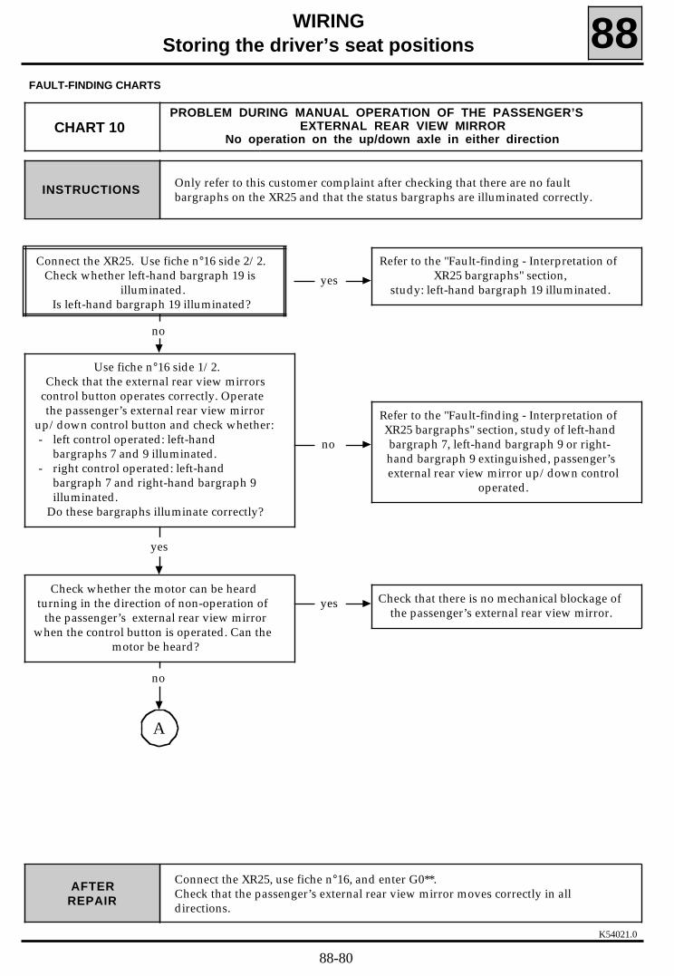
K54021.0
WIRINGStoring the driver’s seat positions 88
FAULT-FINDING CHARTS
Connect the XR25, use fiche n°16, and enter G0**.Check that the passenger’s external rear view mirror moves correctly in alldirections.
AFTERREPAIR
Only refer to this customer complaint after checking that there are no faultbargraphs on the XR25 and that the status bargraphs are illuminated correctly.INSTRUCTIONS
CHART 10PROBLEM DURING MANUAL OPERATION OF THE PASSENGER’S
EXTERNAL REAR VIEW MIRRORNo operation on the up/down axle in either direction
yes
no
Refer to the "Fault-finding - Interpretation ofXR25 bargraphs" section, study of left-handbargraph 7, left-hand bargraph 9 or right-hand bargraph 9 extinguished, passenger’sexternal rear view mirror up/down control
operated.
yes
yes Check that there is no mechanical blockage ofthe passenger’s external rear view mirror.
no
Connect the XR25. Use fiche n°16 side 2/2. Check whether left-hand bargraph 19 is
illuminated. Is left-hand bargraph 19 illuminated?
Refer to the "Fault-finding - Interpretation ofXR25 bargraphs" section,
study: left-hand bargraph 19 illuminated.
A
no
Check whether the motor can be heardturning in the direction of non-operation of
the passenger’s external rear view mirrorwhen the control button is operated. Can the
motor be heard?
Use fiche n°16 side 1/2. Check that the external rear view mirrors
control button operates correctly. Operatethe passenger’s external rear view mirror
up/down control button and check whether:- left control operated: left-hand
bargraphs 7 and 9 illuminated.- right control operated: left-hand
bargraph 7 and right-hand bargraph 9illuminated.
Do these bargraphs illuminate correctly?
88-80

K54021.0
WIRING
Storing the driver’s seat positions 88FAULT-FINDING CHARTS
Connect the XR25, use fiche n°16, and enter G0**.Check that the passenger’s external rear view mirror moves correctly in alldirections.
AFTERREPAIR
yes
Change the computer.
Connect bornier Elé. 1302 to the brown 30-way computer connector. Switch on theignition. To bornier Elé. 1302, connect:
- + after ignition to track 14 and earth ontrack 15. The passenger’s external rear viewmirror should move on the up/down axle.
- + after ignition on track 15 and earth ontrack 14. The passenger’s external rear viewmirror should move on the up/down axlein the opposite direction.Does the passenger’s external rear view
mirror move on the up/down axle in bothdirections?
non
yes no
Repair the faulty electrical wiring.
Change the passenger’sexternal rear view
mirror.
Check the continuity and absence of shortcircuits to earth and to + 12 volts on the
electrical wiring between the brown 30-waycomputer connector:
- A14 and the passenger’s external rearview mirror,
- A15 and the passenger’s rear viewmirror.
Is the electrical wiring in good condition?
CHART 10CONT
A
88-81

K54021.0
WIRINGStoring the driver’s seat positions 88
FAULT-FINDING CHARTS
Connect the XR25, use fiche n°16, and enter G0**.Check that the passenger’s external rear view mirror moves correctly in alldirections.
AFTERREPAIR
Only refer to this customer complaint after checking that there are no faultbargraphs on the XR25 and that the status bargraphs are illuminated correctly.INSTRUCTIONS
CHART 11PROBLEM DURING MANUAL OPERATION OF THE PASSENGER’S
EXTERNAL REAR VIEW MIRRORNo operation on the left/right axle in one direction
no
Refer to the "Fault-finding - Interpretation ofXR25 bargraphs" section, study of right-handbargraph 7, left-hand bargraph 10 or right-hand bargraph 10 extinguished, passenger’sexternal rear view mirror left/right control
operated.
yes
yes Check that there is no mechanical blockage ofthe passenger’s external rear view mirror.
no
yes
Change the computer.
Connect bornier Elé. 1302 to the brown 30-way computer connector. Switch on theignition. To bornier Elé. 1302, connect:
- + after ignition to track 14 and earth ontrack 15. The passenger’s external rear viewmirror should move on the right/left axle.
- + after ignition on track 15 and earth ontrack 14. The passenger’s external rear viewmirror should move on the right/left axlein the opposite direction.Does the passenger’s external rear view
mirror move on the right/left axle in bothdirections?
Check whether the motor can be heardturning in the direction of non-operation of
the passenger’s external rear view mirrorwhen the control button is operated. Can the
motor be heard?
Connect the XR25.Use fiche n°16 side 1/2.Check that the external rear view mirrors
control button operates correctly. Operatethe passenger’s external rear view mirror
left/right control button and check whether:- left control operated: right-hand
bargraph 7 and left-hand bargraph 10illuminated.
- right control operated: right-handbargraphs 7 10 illuminated.
Do these bargraphs illuminate correctly?
no
yes no
Repair the faulty electrical wiring.
Change the passenger’sexternal rear view
mirror.
Check the continuity and absence of shortcircuits to earth and to + 12 volts on the
electrical wiring between the brown 30-waycomputer connector:
- A13 and the passenger’s external rearview mirror,
- A15 and the passenger’s external rearview mirror.
Is the electrical wiring in good condition?
88-82

K54021.0
WIRINGStoring the driver’s seat positions 88
FAULT-FINDING CHARTS
Connect the XR25, use fiche n°16, and enter G0**.Check that the passenger’s external rear view mirror moves correctly in alldirections.
AFTERREPAIR
Only refer to this customer complaint after checking that there are no faultbargraphs on the XR25 and that the status bargraphs are illuminated correctly.INSTRUCTIONS
CHART 12PROBLEM DURING MANUAL OPERATION OF THE PASSENGER’S
EXTERNAL REAR VIEW MIRRORNo operation on the left/right axle in either direction
yes
no
Refer to the "Fault-finding - Interpretation ofXR25 bargraphs" section, study of right-handbargraph 7, left-hand bargraph 10 or right-hand bargraph 10 extinguished, passenger’sexternal rear view mirror left/right control
operated.
yes
yes Check that there is no mechanical blockage ofthe passenger’s external rear view mirror.
no
Connect the XR25. Use fiche n°16 side 2/2. Check whether left-hand bargraph 20 is
illuminated.Is left-hand bargraph 20 illuminated?
Refer to the "Fault-finding - Interpretation ofXR25 bargraphs" section,
study: left-hand bargraph 20 illuminated.
A
no
Check whether the motor can be heardturning in the direction of non-operation of
the passenger’s external rear view mirrorwhen the control button is operated. Can the
motor be heard?
Use fiche n°16 side 1/2.Check that the external rear view mirrors
control button operates correctly. Operatethe passenger’s external rear view mirror
left/right control button and check whether:- left control operated: right-hand
bargraph 7 and left-hand bargraph 10illuminated.
- right control operated: right-handbargraphs 7 and 10 illuminated.
Do these bargraphs illuminate correctly?
88-83

K54021.0
WIRINGStoring the driver’s seat positions 88
FAULT-FINDING CHARTS
Connect the XR25, use fiche n°16, and enter G0**.Check that the passenger’s external rear view mirror moves correctly in alldirections.
AFTERREPAIR
yes
Change the computer.
Connect bornier Elé. 1302 to the brown 30-way computer connector. Switch on theignition. To bornier Elé. 1302, connect:
- + after ignition to track 14 and earth ontrack 15. The passenger’s external rear viewmirror should move on the right/left axle.
- + after ignition on track 15 and earth ontrack 14. The passenger’s external rear viewmirror should move on the right/left axlein the opposite direction.
Does the passenger’s external rear viewmirror move on the right/left axle in bothdirections?
no
yes no
Repair the faulty electrical wiring.
Change the passenger’sexternal rear view
mirror.
Check the continuity and absence of shortcircuits to earth and to + 12 volts on the
electrical wiring between the brown 30-waycomputer connector:
- A13 and the passenger’s external rearview mirror,
- A15 and the passenger’s external rearview mirror.
Le câblage électrique est-il en bon état ?
CHART 12CONT
A
88-84

K54021.0
WIRINGStoring the driver’s seat positions 88
FAULT-FINDING CHARTS
Only refer to this customer complaint after checking that there are no faultbargraphs on the XR25 and that the status bargraphs are illuminated correctly.INSTRUCTIONS
Connect the XR25, use fiche n°16, and enter G0**.Check that both external rear view mirrors move correctly in all directions.AFTER
REPAIR
CHART 13PROBLEM DURING MANUAL OPERATION OF BOTH EXTERNAL REAR
VIEW MIRRORSNo operation on either axle (left/right and up/down)
no Refer to the "Fault-finding - Interpretation ofXR25 bargraphs " section.
yes
Use fiche n°16 side 1/2. Check that theexternal rear view mirrors control buttonoperates correctly. Operate the driver’s
external rear view mirror control button andthen the passenger’s external rear view
mirror control. Check the correct illuminationon the XR25 of bargraphs:
- left-hand bargraph 7 and left-hand bargraph 9, right-handbargraph 9
- left-hand bargraph 7 and left-hand bargraph 10, right-handbargraph 10
- right-hand bargraph 7 and left-hand bargraph 9, right-handbargraph 9
- right-hand bargraph 7 and left-hand bargraph 10, right-handbargraph 10
Do these bargraphs illuminate correctly?
no Repair the faulty electrical wiring.
yes
Change the computer.
Check the continuity and the absence of shortcircuits to earth and to + 12 Volts on theelectrical wiring between track B28 of the
brown 30-way computer connector and themotors of the two external rear view mirrors.
Is the electrical wiring in good condition?
88-85

K54021.0
WIRINGStoring the driver’s seat positions 88
FAULT-FINDING CHARTS
Connect the XR25, use fiche n°16, and enter G0**.Check that both external rear view mirrors move correctly in all directions.AFTER
REPAIR
Only refer to this customer complaint after checking that there are no faultbargraphs on the XR25 and that the status bargraphs are illuminated correctly.INSTRUCTIONS
CHART 14PROBLEM DURING MANUAL OPERATION OF BOTH EXTERNAL REAR
VIEW MIRRORSNo operation on one axle (left/right or up/down)
no Refer to the "Fault-finding - Interpretation ofXR25 bargraphs " section.
yes
Use fiche n°16 side 1/2. Check that theexternal rear view mirrors control buttonoperates correctly. Operate the driver’s
external rear view mirror control button andthen the passenger’s external rear view
mirror control. Check the correct illuminationon the XR25 of bargraphs:
- left-hand bargraph 7 and left-hand bargraph 9, right-handbargraph 9
- left-hand bargraph 7 and left-hand bargraph 10, right-handbargraph 10
- right-hand bargraph 7 and left-hand bargraph 9, right-handbargraph 9
- right-hand bargraph 7 and left-hand bargraph 10, right-handbargraph 10
Do these bargraphs illuminate correctly?
no Repair the faulty electrical wiring.
yes
Change the computer.
Check the continuity and the absence of shortcircuits to earth and to + 12 Volts on the
electrical wiring between the brown 30-waycomputer connector tracks.
- B26 andB3 of the external rearview mirrors
- B27 andA2 control button
Is the electrical wiring in good condition?
88-86

K54021.0
WIRINGStoring the driver’s seat positions 88
FAULT-FINDING CHARTS
Only refer to this customer complaint after checking that there are no faultbargraphs on the XR25 and that the status bargraphs are illuminated correctly.INSTRUCTIONS
Connect the XR25, use fiche n°16, and enter G0**.Check that all of the manual control pad functions operate correctly.AFTER
REPAIR
CHART 15PROBLEM DURING MANUAL OPERATION
General failure of all functions
no Change the faulty fuse.
yes
nonRepair the faulty electrical wiring on
tracks B3 and B4 of the 15-way computerconnector.
Check the condition of the 25 A "Seatmemory" and 15 A "Clock" fuses on the
passenger compartment fuse boardAre the fuses in good condition?
yes
Check the presence of earth ontracks B3 and B4 of the black 15-way
computer connector.Is earth present?
noRepair the faulty electrical wiring on
tracks B1 and B6 of the 15-way computerconnector.
yes
Change the computer.
Check the presence of ~ 12 volts on tracks B1and B6 of the black 15-way computer
connector.Is ~ 12 volts present?
88-87
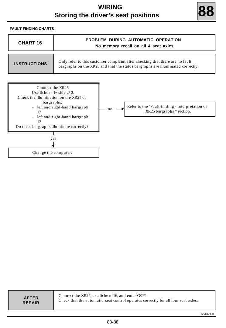
K54021.0
WIRINGStoring the driver’s seat positions 88
FAULT-FINDING CHARTS
Only refer to this customer complaint after checking that there are no faultbargraphs on the XR25 and that the status bargraphs are illuminated correctly.INSTRUCTIONS
Connect the XR25, use fiche n°16, and enter G0**.Check that the automatic seat control operates correctly for all four seat axles.AFTER
REPAIR
CHART 16PROBLEM DURING AUTOMATIC OPERATION
No memory recall on all 4 seat axles
no Refer to the "Fault-finding - Interpretation ofXR25 bargraphs " section.
yes
Change the computer.
Connect the XR25Use fiche n°16 side 2/2.
Check the illumination on the XR25 ofbargraphs:
- left and right-hand bargraph12
- left and right-hand bargraph13
Do these bargraphs illuminate correctly?
88-88

K54021.0
WIRINGStoring the driver’s seat positions 88
FAULT-FINDING CHARTS
Only refer to this customer complaint after checking that there are no faultbargraphs on the XR25 and that the status bargraphs are illuminated correctly.INSTRUCTIONS
Connect the XR25, use fiche n°16, and enter G0**.Check that the automatic seat control operates correctly for all four seat axles.AFTER
REPAIR
CHART 17PROBLEM DURING AUTOMATIC OPERATION
No memory recall on one of the 4 seat axles
nonRefer to the "Fault-finding - Interpretation of
XR25 bargraphs " section,fiche n°16 side 1/2.
yes
Connect the XR25. Use fiche n°16 side 1/2.
Check the illumination on the XR25 of thefollowing bargraphs:
- left-hand bargraph 17 illuminated,selection button "1" pressed
- left-hand bargraph 18 illuminated,selection button "2" pressed
- left-hand bargraph 19 illuminated,selection button "3" pressedAre these bargraphs illuminated?
noRepair the mechanical part of the seat
(condition of the reduction gear drive pipe).
yes
Change the computer.
Carry out all four movements manually.Check that all four movements operate
correctly.Is it possible to control all four movements
manually?
88-89

K54021.0
WIRING
Storing the driver’s seat positions 88FAULT-FINDING CHARTS
Only refer to this customer complaint after checking that there are no faultbargraphs on the XR25 and that the status bargraphs are illuminated correctly.INSTRUCTIONS
Connect the XR25, use fiche n°16, and enter G0**.Check that the two external rear view mirrors return to their stored positionsduring automatic operation.
AFTERREPAIR
CHART 18PROBLEM DURING AUTOMATIC OPERATION
No memory recall on either external rear view mirror
no Refer to Chart 19 and Chart 20.
Connect the XR25. Use fiche n°16 side 2/2.Check the illumination on the XR25 of the
following bargraphs:- left-hand bargraph 16- left and right-hand bargraph
17- left and right-hand bargraph
18- left and right-hand bargraph
19- left and right-hand bargraph
20Are one or more of these bargraphs
illuminated?
yes
Refer to the "Fault-finding - Interpretation ofXR25 bargraphs " section.
88-90

K54021.0
WIRINGStoring the driver’s seat positions 88
FAULT-FINDING CHARTS
Only refer to this customer complaint after checking that there are no faultbargraphs on the XR25 and that the status bargraphs are illuminated correctly.INSTRUCTIONS
Connect the XR25, use fiche n°16, and enter G0**.Check that the driver’s external rear view mirror returns to its stored positionsduring automatic operation.
AFTERREPAIR
CHART 19PROBLEM DURING AUTOMATIC OPERATION
No memory recall on the driver’s external rear view mirror(on one or more movements)
yes Refer to the "Fault-finding - Interpretation ofXR25 bargraphs " section.
no
yes Change the computer.
Move the driver’s external rear view mirrorusing the manual control.
Check that the driver’s external rear view mirror operates correctly
in manual mode.Can the driver’s external rear view mirror be
controlled manually?
no
noRefer to the "Fault-finding - Interpretation of
XR25 bargraphs " section,fiche n°16 side 1/2.
yes
Change the driver’s external rear view mirror.
Connect the XR25.Use fiche n°16 side 1/2.
Check on the XR25 whetherleft-hand bargraphs 7, 9, 10 and
right-hand bargraphs 9, 10 illuminatecorrectly when the driver’s external rear view
mirror control is operated.Do these bargraphs illuminate correctly?
Connect the XR25.Use fiche n°16 side 2/2.Check the illumination on the XR25 of the
following bargraphs:- left-hand bargraph 17 and/or right-hand
bargraph 17 and/or left-hand bargraph 18and/or right-hand bargraph 18.
Are one or more of these bargraphsilluminated?
88-91

K54021.0
WIRINGStoring the driver’s seat positions 88
FAULT-FINDING CHARTS
Connect the XR25, use fiche n°16, and enter G0**.Check that the passenger’s external rear view mirror returns to its stored positionsduring automatic operation.
AFTERREPAIR
Only refer to this customer complaint after checking that there are no faultbargraphs on the XR25 and that the status bargraphs are illuminated correctly.INSTRUCTIONS
CHART 20PROBLEM DURING AUTOMATIC OPERATION
No memory recall on the passenger’s external rear view mirror(on one or more movements)
yes Refer to the "Fault-finding - Interpretation ofXR25 bargraphs " section.
no
yes Change the computer.
Move the passenger’s external rear viewmirror using the manual control.
Check that the passenger’s external rear view mirror operates correctly
in manual mode.Can the passenger’s external rear view mirror
be controlled manually?
no
noRefer to the "Fault-finding - Interpretation of
XR25 bargraphs " section,fiche n°16 side 1/2.
yes
Change the passenger’s external rear viewmirror.
Connect the XR25.Use fiche n°16 side 1/2.
Check on the XR25 whetherleft-hand bargraphs 7, 9, 10 and
right-hand bargraphs 9, 10 illuminatecorrectly when the passenger’s external rear
view mirror control is operated.Do these bargraphs illuminate correctly?
Connect the XR25.Use fiche n°16 side 2/2.Check the illumination on the XR25 of the
following bargraphs:- left and right-hand bargraph
19- left and right-hand bargraph
20Are one or more of these bargraphs
illuminated?
88-92

K54021.0
WIRINGStoring the driver’s seat positions 88
FAULT-FINDING CHARTS
Only refer to this customer complaint after checking that there are no faultbargraphs on the XR25 and that the status bargraphs are illuminated correctly.INSTRUCTIONS
Connect the XR25, use fiche n°16, and enter G0**.Check that the driver’s external rear view mirror returns to its stored positionsduring automatic operation.
AFTERREPAIR
CHART 21PROBLEM DURING AUTOMATIC OPERATION
No memory recall on the seat and external rear view mirrors
functions
noRefer to the "Fault-finding - Interpretation ofXR25 bargraphs " section, study for left-hand
bargraph 19, fiche n°16 side 1/2.
Connect the XR25. Use fiche n° 16 side 1/2.Check whether left-hand bargraph 19 is
illuminated when selection button "3" ispressed.
Is this bargraph illuminated?
yes
no Repair the faulty electrical wiring.
yes
Change the computer.
Check the continuity and the absence of shortcircuits to earth and to + 12 volts on theelectrical wiring between track 10 of the
green 15-way computer connector and trackA5 of the automatic control pad.
Is the electrical wiring in good condition?
88-93

K54021.0
WIRINGStoring the driver’s seat positions 88
FAULT-FINDING CHARTS
Only refer to this customer complaint after checking that there are no faultbargraphs on the XR25 and that the status bargraphs are illuminated correctly.INSTRUCTIONS
Connect the XR25, use fiche n°16, and enter G0**.Check that the seat and the external rear view mirrors return to their storedpositions when the automatic control is operated.
AFTERREPAIR
CHART 22PROBLEM DURING AUTOMATIC OPERATION
No memory recall of one stored position (1, 2 or 3)
noRefer to the "Fault-finding - Interpretation ofXR25 bargraphs " section, study for left-hand
bargraph 19, fiche n°16 side 1/2.
Connect the XR25. Use fiche n° 16 side 1/2.Check whether left-hand bargraph 17 isilluminated with selection button "1"
pressed.Is this bargraph illuminated?
yes
noRefer to the "Fault-finding - Interpretation ofXR25 bargraphs " section, study for left-hand
bargraph 19, fiche n°16 side 1/2.
yes
Change the computer.
XR25 still connected, use fiche n°16 side 1/2.Check whether left-hand bargraph 18 isilluminated with selection button "2"
pressed.Is this bargraph illuminated?
yes
noRefer to the "Fault-finding - Interpretation ofXR25 bargraphs " section, study for left-hand
bargraph 19, fiche n°16 side 1/2.
XR25 still connected, use fiche n°16 side 1/2.Check whether left-hand bargraph 19 isilluminated with selection button "3"
pressed.Is this bargraph illuminated?
88-94

K54021.0
WIRINGStoring the driver’s seat positions 88
FAULT-FINDING CHARTS
Only refer to this customer complaint after checking that there are no faultbargraphs on the XR25 and that the status bargraphs are illuminated correctly.INSTRUCTIONS
Connect the XR25, use fiche n°16, and enter G0**.Store a seat position. Then check that it has been stored correctly by recalling itusing the automatic control pad.
AFTERREPAIR
CHART 23PROBLEM DURING AUTOMATIC OPERATION
A position cannot be stored
noRefer to the "Fault-finding - Interpretation of
XR25 bargraphs " section,fiche n°16 side 1/2.
yes
Change the computer.
Connect the XR25. Use fiche n° 16 side 1/2.Check on the XR25 that:
- right and left-hand bargraph 17 andright-hand bargraph 19 are illuminatedwhen the "STORE" button on the manualcontrol is pressed,
- right and left-hand bargraph 17 andright-hand bargraph 19 are extinguishedwhen the "STORE" button on the manualcontrol pad is released,
Do these bargraphs illuminate correctly?
88-95
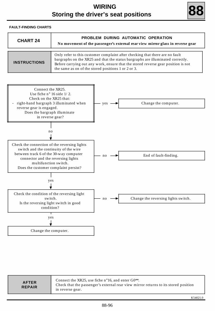
K54021.0
WIRINGStoring the driver’s seat positions 88
FAULT-FINDING CHARTS
Only refer to this customer complaint after checking that there are no faultbargraphs on the XR25 and that the status bargraphs are illuminated correctly.Before carrying out any work, ensure that the stored reverse gear position is notthe same as on of the stored positions 1 or 2 or 3.
INSTRUCTIONS
Connect the XR25, use fiche n°16, and enter G0**.Check that the passenger’s external rear view mirror returns to its stored positionin reverse gear.
AFTERREPAIR
CHART 24PROBLEM DURING AUTOMATIC OPERATION
No movement of the passenger’s external rear view mirror glass in reverse gear
yes Change the computer.
no
no End of fault-finding.
yes
Check the connection of the reversing lightsswitch and the continuity of the wire
between track 6 of the 30-way computerconnector and the reversing lights
multifunction switch.Does the customer complaint persist?
Connect the XR25.Use fiche n° 16 side 1/2.Check on the XR25 that:
- right-hand bargraph 3 illuminated whenreverse gear is engaged.
Does the bargraph illuminatein reverse gear?
no Change the reversing lights switch.
yes
Change the computer.
Check the condition of the reversing lightswitch.
Is the reversing light switch in goodcondition?
88-96

K54021.0
WIRINGStoring the driver’s seat positions 88
FAULT-FINDING CHARTS
Only refer to this customer complaint after checking that there are no faultbargraphs on the XR25 and that the status bargraphs are illuminated correctly.INSTRUCTIONS
Connect the XR25, use fiche n°16, and enter G0**.Check that the seat returns to a stored position correctly when the automaticcontrol pad is operated.
AFTERREPAIR
CHART 25PROBLEM DURING AUTOMATIC OPERATION
Recall of a stored position incorrect (one or more axles)
no
Check that nothing is disturbing theoperation of of the axle(s) concerned.
Note: if one of the axles if damaged,reinitialisation will be necessary.
yes
Refer to the "Fault-finding - Interpretation ofXR25 bargraphs" section,
fiche n°16 side 2/2.
Connect the XR25.Use fiche n° 16 side 2/2.
Move the seat and check whetherone or more fault bargraphs
are illuminated.Are one or more bargraphs illuminated?
88-97