ms tower v6
DESCRIPTION
design of telecommunication towersTRANSCRIPT

MStower V6
User’s Manual
Engineering Systems

COPYRIGHT NOTICE(C) Copyright Engineering Systems (EEC) Limited 1997-2008. All rights are reserved. The copyright applies tothis manual and to the corresponding software (together referred to herein as the “licensed material”).
DISCLAIMERSubject to limitations imposed by law, Engineering Systems (EEC) Limited makes no warranty of any kind inconnection with the licensed material. Engineering Systems (EEC) Limited shall not be liable for any errorscontained in the licensed material nor for any incidental or consequential damages resulting from the use of thelicensed material. Engineering Systems (EEC) Limited is not engaging in the provision of consulting services insupplying the licensed material. Users of the licensed material are advised that output from computer softwareshould be subjected to independent checks. Engineering Systems (EEC) Limited reserves the right to revise andotherwise change the licensed material from time to time without notification, or provision of revised material.
SOFTWARE LICENCEThe software is supplied to the user under licence. It may be installed on as many computers as required but thenumber of concurrent users must not exceed the number of licences held. For network licences, use is permittedonly in the country for which the licence was supplied. The software may not be sub-licensed, rented, or leased toanother party. The licence can only be transferred to another party at the discretion of Engineering Systems (EEC)Limited.
Engineering Systems (EEC) LimitedSystems House27 Highclere DriveHemel Hempstead HERTS HP3 8BYEngland
Tel: +44 (0) 144 226 2647E-mail: [email protected]: www.mstower.com
April, 2008
Crystal Palace Tower, LondonThis is Britain’s tallest unguyed steel tower. It was checked for structural adequacy using MStower.

Preface
MStower is a software package for the analysis and design of towers, masts, and poles. This softwareincorporates the very latest in Windows technology to make it easier to use and improve yourproductivity.
“1:Introduction” provides an overview of the capabilities of MStower. Whether you are installingMStower for the first time or updating an existing system, you will find all the necessary informationin “2:Getting Started”. “3:Menus & Toolbars” provides a summary of the commands available andother chapters provide reference and technical information.
This manual is available to the MStower user on-line, together with “pop-up” help for toolbar buttonsand dialog boxes. The on-line Help system provides a synchronized table of contents and powerfulmethods of searching for topics.
If the file Readme.txt is present in the MStower program folder after installation, you should read itfor information that became available after the manual was printed. The file is automatically displayedduring installation but it may be displayed in Notepad at any time by double-clicking the file inWindows Explorer.


MSTower V6 Contents • i
Contents
1:Introduction 1General...................................................................................................................................... 1Responsibility ........................................................................................................................... 4Acknowledgement .................................................................................................................... 5Enhancement Record ................................................................................................................ 5
2:Getting Started 9Installing MStower ................................................................................................................... 9Hardware Lock ......................................................................................................................... 9Folders .................................................................................................................................... 10Starting MStower.................................................................................................................... 11Commands .............................................................................................................................. 12Right-Clicking Away from Any Part of the Tower ................................................................ 12How to Make a Shortcut on the Desktop ................................................................................ 13Launch with Double-Click...................................................................................................... 13Configuration.......................................................................................................................... 14Printing in MStower ............................................................................................................... 15
Print and Print Preview Commands.......................................................................... 15The Windows Print Dialog Box ............................................................................... 15The Page Setup Dialog Box ..................................................................................... 16Configurable User Graphic....................................................................................... 18
Steel Section Libraries ............................................................................................................ 18Data from Earlier Versions ..................................................................................................... 19Technical Support ................................................................................................................... 19Web Update ............................................................................................................................ 20
3:Menus & Toolbars 21Layout..................................................................................................................................... 21File Menu Commands............................................................................................................. 22View Menu Commands .......................................................................................................... 23Tower Menu Commands ........................................................................................................ 24Member Checking Menu Commands ..................................................................................... 24Structure Menu Commands .................................................................................................... 25Analyse Menu Commands...................................................................................................... 26Results Menu Commands ....................................................................................................... 27Reports Menu Commands ...................................................................................................... 27Show Menu Commands.......................................................................................................... 28

ii • Contents MSTower V6
Query Menu Commands .........................................................................................................29Window Menu Commands......................................................................................................30Help Menu Commands............................................................................................................31Main Toolbar Commands........................................................................................................31View Toolbar Commands .......................................................................................................32Display Toolbar Commands....................................................................................................33Help Toolbar Commands ........................................................................................................33Draw Toolbar Commands .......................................................................................................34Attributes Toolbar Commands ................................................................................................34Results Toolbar Commands ....................................................................................................35OK/Cancel Toolbar Commands ..............................................................................................35Extra Buttons Toolbar Commands ..........................................................................................36Selecting Which Toolbars Are Displayed ...............................................................................36Customizing Toolbars .............................................................................................................37The Ouput Window.................................................................................................................37
4:Operation 39Data Files ................................................................................................................................39
Units..........................................................................................................................40Coordinate Systems ..................................................................................................40Sections.....................................................................................................................41Member Checking.....................................................................................................41Export to Microstran Archive File ............................................................................41
Errors.......................................................................................................................................41
5:Tower Data 43General ....................................................................................................................................43The Tower Data (TD) File ......................................................................................................44
Title Block ................................................................................................................45Component Block .....................................................................................................45Profile Block .............................................................................................................46Supports Block..........................................................................................................53Guys Block ...............................................................................................................54Sections Block ..........................................................................................................55Material Block ..........................................................................................................58Bolt Data Block ........................................................................................................58
Guy Library.............................................................................................................................61Steel Poles ...............................................................................................................................62TD File Examples ...................................................................................................................65
Example 1 .................................................................................................................65Example 2 .................................................................................................................66Example 3 .................................................................................................................67Example 4 .................................................................................................................68Example 5 (Plan Bracing) .........................................................................................70
6:Standard Panels 71General ....................................................................................................................................71

MSTower V6 Contents • iii
Index – Face Panels ................................................................................................................ 72Index – Plan Bracing .............................................................................................................. 76Index – Hip Bracing & Cross-Arms ....................................................................................... 77D & V Face Panels ................................................................................................................. 78X Face Panels ......................................................................................................................... 79K Face Panels ......................................................................................................................... 84M Face Panels......................................................................................................................... 94W Face Panels......................................................................................................................... 96XMA Face Panel..................................................................................................................... 98XDMA Face Panel.................................................................................................................. 99DM, DM2 Face Panel ........................................................................................................... 100DMH, DMH2 Face Panel ..................................................................................................... 101DLM, DLM2 Face Panel ...................................................................................................... 102KXM, KXM2 Face Panel ..................................................................................................... 103SH3, SH4 .............................................................................................................................. 104Plan Bracing ......................................................................................................................... 105Hip Bracing........................................................................................................................... 112Cross-Arms........................................................................................................................... 115
7:User-Defined Panels 117General.................................................................................................................................. 117The UDP File........................................................................................................................ 118Making A UDP Using Graphics Input.................................................................................. 122UDPs for Poles ..................................................................................................................... 122Modifying An Existing UDP ................................................................................................ 123Towers With Unequal Length Legs...................................................................................... 123Creating a UDP from a Microstran Job ................................................................................ 124UDP File Names ................................................................................................................... 125
8:Graphics Input for UDPs 127General.................................................................................................................................. 127Basic Drawing ...................................................................................................................... 128The Drawing Snap Mode...................................................................................................... 130The Drawing Plane ............................................................................................................... 131Automatic Removal of Duplicate Nodes and Members ....................................................... 131Cursors.................................................................................................................................. 132Shortcut Keys ....................................................................................................................... 133Selecting Nodes and Members ............................................................................................. 133Right-Clicking on Nodes and Members ............................................................................... 134The Node Properties Dialog Box.......................................................................................... 135The Member Properties Dialog Box ..................................................................................... 135Properties Dialog Boxes with Multiple Selection................................................................. 136Extrusion............................................................................................................................... 136Interrupting Commands ........................................................................................................ 136The Stretch Command .......................................................................................................... 137The Limit Command............................................................................................................. 138Removing an Intermediate Node .......................................................................................... 139UDP Graphical Example ...................................................................................................... 140

iv • Contents MSTower V6
Step 1 – Create Data File for a Small Tower ..........................................................140Step 2 – Build Tower ..............................................................................................142Step 3 – Isolate UDP Members...............................................................................142Step 4 – Add Members to UDP ..............................................................................143Step 5 – Define Attributes of New Members..........................................................144Step 6 – Copy New Members to Other Faces .........................................................144Step 7 – Set Reference Nodes for New Members ...................................................145Step 8 – Check UDP ...............................................................................................145Step 9 – Convert Graphics to UDP File ..................................................................145
9:Tower Loading 147General ..................................................................................................................................147The Tower Loading (TWR) File ...........................................................................................148
Parameters Block ....................................................................................................148Damping .................................................................................................................152Basic Velocity.........................................................................................................152Terrain Block ..........................................................................................................153Velocity Profile Block ............................................................................................159Named Node Block.................................................................................................160Guy List Block........................................................................................................161External Factor Block .............................................................................................162Loads Block ............................................................................................................162Wind Load Cases ....................................................................................................163Cross-arms and Similar Members External to the Main Tower Body ....................165Guyed Mast Patch Loadings ...................................................................................165Dead Loads .............................................................................................................166Ice Loads.................................................................................................................166Miscellaneous Loads...............................................................................................167Additional Node Loads ...........................................................................................167Additional Member Temperatures ..........................................................................167Eathquake Load Cases ............................................................................................168Combination Load Cases ........................................................................................170Panel Block .............................................................................................................170Ancillary Block.......................................................................................................171
Output....................................................................................................................................178Computation of Wind Resistance..........................................................................................179
BS 8100 ..................................................................................................................179AS 3995 ..................................................................................................................180AS 1170 ..................................................................................................................180Malaysian Electricity Supply Regulations 1990 .....................................................180EIA/TIA-222-F .......................................................................................................181TIA-222-G ..............................................................................................................181
Computation of Deflections ..................................................................................................182BS 8100 ..................................................................................................................182Other Codes ............................................................................................................182
Dynamic Amplification of Wind Loads ................................................................................183BS 8100 ..................................................................................................................183AS 3995 ..................................................................................................................183AS 1170 ..................................................................................................................184

MSTower V6 Contents • v
EIA-222-F .............................................................................................................. 184TIA-222-G.............................................................................................................. 184ASCE 7................................................................................................................... 184IS 875 ..................................................................................................................... 185BNBC..................................................................................................................... 185ILE TR7.................................................................................................................. 185
Ancillary Libraries................................................................................................................ 186Large Ancillary Library.......................................................................................... 186Linear Ancillary Library......................................................................................... 188Drag Coefficients ................................................................................................... 189
10:CAD Interface 191General.................................................................................................................................. 191Exporting a CAD DXF ......................................................................................................... 191Exporting a Steel Detailing Neutral File............................................................................... 192Section Alias File.................................................................................................................. 193Windows Clipboard Operations............................................................................................ 193
11:Analysis 195General.................................................................................................................................. 195
Method ................................................................................................................... 196Consistency Check ................................................................................................. 196Accuracy................................................................................................................. 196
Linear Elastic Analysis ......................................................................................................... 197Non-Linear Analysis............................................................................................................. 197
Second-Order Effects ............................................................................................. 198Running a Non-Linear Analysis ............................................................................. 200Troubleshooting Non-Linear Analysis ................................................................... 203
Elastic Critical Load Analysis .............................................................................................. 204Selecting Load Cases for ECL Analysis................................................................. 205Analysis Control Parameters .................................................................................. 205Why ECL Analysis May Give High k Factors ....................................................... 206
Dynamic Analysis................................................................................................................. 207Analysis Control Parameters .................................................................................. 207Dynamic Modes ..................................................................................................... 208
Response Spectrum Analysis................................................................................................ 209Defining Load Cases .............................................................................................. 209Running a Response Spectrum Analysis ................................................................ 209Response Spectrum Curves .................................................................................... 212
Errors .................................................................................................................................... 213
12:Member Checking 215General.................................................................................................................................. 215Operation .............................................................................................................................. 216Loading Parameters .............................................................................................................. 216
BS 8100 Part 3........................................................................................................ 216BS 449 .................................................................................................................... 216

vi • Contents MSTower V6
ASCE 10-90, ASCE 10-97, ASCE Manual 72 .....................................................217EIA-222-F...............................................................................................................217TIA-222-G ..............................................................................................................217AS 3995 ..................................................................................................................217IS 802......................................................................................................................217ILE TR7 ..................................................................................................................217BS 5950 ..................................................................................................................218AS 4100 ..................................................................................................................218
Design Loads.........................................................................................................................218Member Checks to BS 8100 Part 3 .......................................................................................219Member Checks to BS 449....................................................................................................220Member Checks to AS 3995 .................................................................................................221Member Checks to ASCE 10-90 1991 & ASCE 10-97 1991................................................222Member Checks to EIA-222-F 1998 .....................................................................................223Member Checks to TIA-222-G 2005 ....................................................................................225Member Checks to IS 802.....................................................................................................226Member Checking to ILE Technical Report 7 ......................................................................226Member Checking to BS 5950 ..............................................................................................227Member Checking to AS 4100..............................................................................................227Member Checking to ASCE Manual 72................................................................................227Obtaining Design Results......................................................................................................228Steel Detailing.......................................................................................................................228Editing Ancillary & Guy Libraries........................................................................................228
13:Editing the Section Library 229General ..................................................................................................................................229Section Library......................................................................................................................229Section Library Manager.......................................................................................................233Compiling a Library..............................................................................................................236Editing a Library with a Text Editor .....................................................................................236Library Viewer ......................................................................................................................237
14:Reports 239Report Types .........................................................................................................................239Display and Printing of Files.................................................................................................240Input/Analysis Report ...........................................................................................................240Error Report ..........................................................................................................................241Static Log ..............................................................................................................................241Dynamic Log.........................................................................................................................241Design Summary...................................................................................................................241Detailed Design Report .........................................................................................................242Reaction Report.....................................................................................................................242Rotation Report .....................................................................................................................242
15:Examples 243General ..................................................................................................................................243TWEX1 .................................................................................................................................246

MSTower V6 Contents • vii
15:Ancillary Programs 253CTIDATA............................................................................................................................. 253
Index 255


MSTower V6 1:Introduction • 1
1:Introduction
GeneralMStower is a specialized program that assists in the analysis andchecking of latticed steel communication and power transmission towersand guyed masts and steel monopoles. MStower contains options fordefining the geometry, loading, analysis, plotting of input, results, andmember checking.Loading may be computed in accordance with:
• BS 8100 Part 1 1986• BS 8100 Part 4 1995• AS 3995-1994• AS/NZS 1170.2:2002• Malaysian Electricity Supply Regulations 1990• EIA/TIA-222-F-1996.• TIA-222-G-2005.• Institution of Lighting Engineers Technical Report No. 7 –
High Masts for Lighting and CCTV – 2000 Edition.• IS 875 (Part 3):1987• BNBC 93 – Bangladesh National Building Code• ANSI/ASCE 7-95• NSCP C101-01 – Philippines National Building Code
Member capacities may be checked against the requirements of:• BS 8100 Part 3• BS 449• AS 3995-1994• ASCE 10-90, ASCE 10-97• EIA/TIA-222-F-1996• TIA-222-G-2005.

2 • 1:Introduction MSTower V6
• Institution of Lighting Engineers Technical Report No. 7 –High Masts for Lighting and CCTV – 2000 Edition.
• BS 5950-1:2000 (for tubular poles)• IS 802 (Part 1 / Sec. 2):1992
Towers, which may be of three or four sides or a single cantileveredtubular pole, are assembled by combining a series of standard face, plan,hip, and cross-arm panels. The tower profile is defined by giving theheight of individual panels and the width at “bend” points. All otherwidths are obtained by interpolation. The range of standard panels isbeing regularly increased with over 100 different panel types available atpresent. A number of the standard panels are parameterised so that theuser may readily modify the configuration.If a suitable standard panel is not available the system accepts “user-defined panels” (UDP). While these require much more data than astandard panel, they allow the system to be used for virtually any towerconfiguration. A UDP may consist of anything from a few members thatmake up half a face panel to a full three-dimensional section of thetower.The result of the tower building process is a complete MStower data file,Job.mst, where “Job” is the MStower job name.The loading module of MStower computes loads due to self-weight, ice,and wind on the tower. As well as computing wind loads on the baretower the program is able to take account of a wide range of ancillaryitems found on communication towers.Ancillaries are classified into the following categories:
• Linear ancillaries, normally within the body of the tower andconsisting of items such as ladders, feeders and wave-guides.
• Face ancillaries, attached to the face of the tower and consistingof small items such as minor antennae, gusset plates andplatforms.
• Large ancillaries, mounted out from the face of the tower andconsisting of large dishes whose wind resistance is significantcompared with that of the structural members of the tower.
• Resistance. A group of ancillaries may be described by theirwind resistance over a height range of the tower.
• Insulators, located between the segments of multi-segmentguys.
Ancillary libraries containing data describing the physical and dragcharacteristics of a wide range of antennae types are provided withMStower. The libraries are plain text files and may be easily added to byusers. For a dish antenna the library would typically include its diameter,mass, location of center of gravity, surface area that may be coated with

MSTower V6 1:Introduction • 3
ice, and its projected area and a drag coefficients for a range of angles ofincidence.Six aerodynamic coefficients are specified for each angle of incidence toenable antenna forces and moments to be computed automatically.The use of ancillary libraries simplifies the preparation of the dataneeded to compute the loads on the tower. To fully describe an antennaits library reference, its location on the tower, and its bearing arerequired. MStower will extract all other data from the library, computethe forces acting on the antenna (dead load, ice-load, and wind loads)and transfer them into the tower as a set of statically equivalent forces.To assist in checking of input data MStower displays the tower and alllinear and large ancillaries. As well as the visual display, any ancillarymay be queried by “picking” with the graphics cursor to obtain itsidentification, location, library reference, and other pertinent data.The strength of members may be checked against the rules of the codeslisted above, with the results available as a summary report giving thecritical load case and condition or a larger detailed report suitable forchecking the computations for each member. The results of the membercheck may be shown as a graphical display with the color in which amember is displayed depending on its maximum load/capacity ratio.Foundation reactions and ancillary rotations may also be reported.

4 • 1:Introduction MSTower V6
ResponsibilityMStower is intended to assist designers in performing the necessarycalculations for checking and designing towers, guyed masts, and steelmonopoles. Users must have an understanding of these structures and agood knowledge of the codes of practice to which they are working.MStower cannot replace sound and responsible engineering judgementand practice.The interpretation of the output from MStower and the application ofthis data is solely the responsibility of the user.Good engineering practice requires fully triangulated bracing systems intowers. Tower design codes do not check for bending stresses inmembers or their bending stiffness, so members in bending should not beused to restrain compression members. Features to check for include:
• Plan bracing must be fully triangulated to provide restraint andmaintain the plan shape of the tower.
• Hip bracing must be fully triangulated and connected to theplan bracing system within a panel to resist twisting of thewhole leg/hip bracing assembly.
• Bend points in K brace arrangements must have the knee fullybraced in two directions.
• The ends of K brace members must be restrained and coincidewith plan bracing members at the top of the panel.
• Leg bend points must be fully braced in two directions.• Where leg members join in towers with staggered face bracing,
restraint should be provided in the unbraced face by planbracing or a similar system.
MStower is not able to detect automatically the lack of restraint in non-triangulated arrangements. If non-triangulated bracing is used,additional manual checks to the relevant design code must be made toensure that there is sufficient strength and stiffness to provide adequaterestraint to other members.Designers should consider the safety of any temporary arrangementsduring construction.

MSTower V6 1:Introduction • 5
AcknowledgementInitial development of sections of MStower was done under contractswith the Independent Broadcasting Authority, Eastern Electricity, BritishTelecom, and the British Broadcasting Corporation.Particular recognition is due to Mr M J Lambert of the IndependentBroadcasting Authority who initiated this work.
Enhancement RecordVersion 3.1New menu introduced.TWR file format revised.Terrain blocks introduced.Linear and large ancillary libraries introduced.32 bit version of programs introduced.Additional standard panels introduced.GUST and MEAN keywords added to TWR file.Graphical input of UDPs introduced.
Version 3.15Screen querying of linear ancillary, large ancillary, and ancillary groupsintroduced with graphical representation of larger ancillaries.Ancillary libraries extended to include Andrew information.HP LaserJet printers now supported for plotting.PostScript format available for output files.Ancillary deflections and rotations calculated.Foundation reactions calculated.CROSS and BARE keywords added.Total mass and additional mass of ancillaries in TWR file.XIP, plan bracing at intersection point of face bracing.Optional Velocity Profile.
Version 4Masts including catenary cables to BS 8100 Part 4 and AS 3995.Additional standard panels.Named node block introduced.Supports block.
6 • 1:Introduction MSTower V6
Version 4.1EIA/TIA-222-F-1996.ASCE 10-90 1991 (Manual 52).Bolt checking to DD133/BS5950.Deflections/rotations.
Version 4.15Manual re-set in Microsoft Word.Examples revised.Partial safety factors for materials now applied at member checkingstage.Database utilities added.Bolt data file included.
Version 4.20Shade factor introduced for linear and large ancillaries.Job.out file enhanced for results checking.
Version 4.21Tension-only members now available in UDPs; non-linear analysismodule required.
Version 5New 32-bit Windows version. Ancillary display improved; split viewwith ancillary labelling. Database recognition and automatic loadingfrom CSV files. Enhanced metafile export of views. Non-linear analysisconvergence parameters added. Smear loading for wind on guys. UDPinput completely revised. Support for DOS discontinued.Generation of TD and TWR files. Multi-segment guys and guyinsulators supported. Asymmetrical ice loading added. Bolt checking toAS 3995, EIA-222, and ASCE 10-90 added.
Version 6Rectangular towers may be generated directly from standard panels.Different bracing patterns and sizes may be generated on X and Y facesof four sided towers using standard panels.Loading to AS/NZS 1170.2:2002, IS 875, BNBC, ASCE 7-95,Philippines NBC.Earthquake loading.

MSTower V6 1:Introduction • 7
Greater user control over the manner in which ancillary resistance isused.Generation, loading, and checking of steel monopoles.Virtual reality graphics.Gust response factor calculations for dynamically sensitive towers forsome codes.Member checking to ASCE 10-97, IS 802.Member checking to BS 8100 Part 4 replaces DD133-1986.Panels may have one or two sets of plan bracing.UDP member classes specified directly.Section Library Manager.Web downloads.TIA-222-G-2005 implemented.

8 • 1:Introduction MSTower V6

MSTower V6 2:Getting Started • 9
2:Getting Started
Installing MStowerThe Setup program will install MStower on your computer. Usually,Setup will begin when you insert the CD. If Setup does not beginautomatically you must perform these steps:• Click on the Windows Start button and select Run.• Browse to the Setup program on the distribution CD.• Execute the Setup program.Setup will guide you through the installation process, prompting you fora name for the program folder (the default is C:\Mstower), and thencopying the required files to the hard disk. Necessary fonts will beinstalled.
Hardware LockMStower is normally supplied with a USB hardware lock that must beattached to the computer before you can start the program. Additionalset-up procedures are required for systems with a network lock. Theseare described on a separate data sheet.

10 • 2:Getting Started MSTower V6
FoldersThe Setup program will establish a number of folders under the specifiedMStower folder. If you use the default name the folders as displayed inWindows Explorer will look like this:
MSTOWER FOLDERS
Folder Name CommentMstower MStower folder – you can choose this name during
installation. “Mstower” is the default.
.....Data Default data folder – you can open MStower files in otherfolders if you wish.
.....Examples Example files – useful for testing and learning.
.....PDF Contains documentation in PDF format, including full usermanual.
.....Program All MStower program files, library files, and Help files.
.....Service For network version only, this folder contains networksupport and documentation files.
Library File FolderYou may use the File > Configure > General > Library File Foldercommand to specify a folder for library files anywhere on the computeror in the Network Neighborhood. Files in this folder will be accessedwhen you refer to a library file with the “L:” prefix. Using the “P:”prefix will cause MStower to look in the Program folder for library files.Library file references that do not have a prefix cause MStower to lookin the data folder for library files.

MSTower V6 2:Getting Started • 11
Temporary File FolderBy default, MStower writes intermediate data to the Windows temporaryfile folder. This is usually most satisfactory for all types of installation.You may, however, use the File > Configure > General > TemporaryFile Folder command to specify a different folder anywhere on thecomputer or in the Network Neighborhood.
Starting MStowerThe Setup program creates an MStower item on the Windows Programsmenu (click Start, then Programs). Click on this item to start MStower.If you have not previously used MStower you should start with some ofthe examples supplied with MStower to familiarize yourself with theoperation of the principal menu and toolbar items (seeChapter 15:Examples on page 243). To run an example, use the File >Open command and click on the required file in the dialog box.You may open any existing MStower job with the File > Opencommand. To start a new job based on an old job, open the old job andsave a copy with another name using the File > Save Copy Ascommand. You may now close the old job and open the new copy byselecting its name from the most recently used list on the File menu.Note the following powerful Help features, which make it easier for youto use MStower:• There are tooltips on all toolbar buttons. Move the mouse cursor
over the button for a moment and a little pop-up window displaysthe function of the button.
• There is a prompt displayed on the left side of the status bar (at thebottom of the MStower window) whenever the cursor is positionedover a toolbar button or a menu item. Look here for prompts whileyou are performing input operations.
• Context-sensitive help is available for all toolbar buttons by clickingthe button. Once you have clicked this button, move the newcursor to any item and click.
• Context-sensitive (pop-up) help is available in dialog boxes. Someitems in dialog boxes also have tooltips.
Use the Help > MStower Help Topics command to display the HelpTopics dialog box. With this, you can browse the table of contents, lookthrough an index, or search all Help topic keywords.

12 • 2:Getting Started MSTower V6
CommandsMStower commands are available from:
• The main menu.• Toolbar buttons.• The context menu.
Generally, all the commands are available on the main menu, while, forconvenience, some of them are also available on toolbar buttons or thecontext menu. Commands selected from the main menu are referred to inthis manual as shown in this example:View > Zoom > WindowCommands selected by clicking a toolbar button are referred to by thename of the button, as shown in the tooltip.
Right-Clicking Away from Any Part of the TowerWhen you right-click in the main window, away from any node ormember, the pop-up menu below appears.
MAIN CONTEXT MENU
This provides a very convenient alternative to the main menu for manycommands. In effect, you can perform some operations in three differentways. For example, you can display the section number on all membersby clicking a button on the Display toolbar, by selecting the View >Display Options command, or by right-clicking and then selectingSection Numbers.

MSTower V6 2:Getting Started • 13
How to Make a Shortcut on the DesktopTo make a shortcut to MStower on your desktop (the background that isvisible when no programs are running), drag the MStower icon from theStart > Programs menu while holding down the Ctrl key.
Launch with Double-ClickMStower job files (Job.mst, where “Job” is the job name) should beidentified in Explorer with a distinctive icon. It is convenient to be ableto double-click on one of these files in Explorer to start MStower withthe job. To do this, the MST file type must be associated with MStower.The association between MStower and the MST file type may beestablished when MStower is installed. You may also establish theassociation with the procedure set out below.Here are the steps necessary to make MStower launch with a double-click:• In Explorer select the View > Folder Options or View > Options
command.• Select the File Types tab.• In the list box search for the MStower job file type, which may be
shown as “MST File” or “MStower Document”. If found, select thisfile type and click the Remove button. Close the dialog box.
• In Explorer browse to the MStower data folder and double-click onany MStower job file (if the file name extension “mst” is not visibleyou may see it by right-clicking and checking the properties of thefile).
• The Open With dialog box appears. Click on the Other button andbrowse to Mst.exe in the MStower program folder.
• In the Description box type “MStower Job File” and click OK.• In Explorer select the View > Folder Options or View > Options
command.• Select the File Types tab, then select “MStower Job File” in the list
box and click the Edit button.• Click the Change Icon button and then select the second icon.• Click OK to close the Edit File Type dialog box.• Click OK to close the Folder Options dialog box.Now, check that you have successfully set up your system by browsingto an MStower job file and double-clicking.

14 • 2:Getting Started MSTower V6
ConfigurationThe first time you start MStower it will run in a partial screen window.Maximize the Window (use the button next to the X button at the top rightof the MStower window) and the system will thereafter start in a full-screen window.Toolbars may be activated or de-activated using the View > Toolbarscommand and they may also be floated or moved to different locationson the main window if desired (“docked”). Toolbar buttons may bedragged from one toolbar to another while the Alt key is held down.Chapter 3 contains more information on how you can customize thetoolbars.The File > Configure command allows you to set program parameterssuch as colors, default library files and design codes, and maximum jobsize. The default settings for maximum job size will be sufficient for themajority of jobs. Increasing limits unnecessarily can result in slightlyreduced operating speed.
FILE > CONFIGURE

MSTower V6 2:Getting Started • 15
Printing in MStower
Print and Print Preview CommandsMStower differs from many standard Windows application in that thereis a requirement to print both files (reports) and pictures. As in astandard Windows application, MStower has a Print command on theFile menu (File > Print File). This is for printing files and reports. Also,there is a Print command on the View menu (View > Print View) andthis is used for printing pictures of the structure. The File menu is shownin “File Menu Commands” on page 22 and the View menu is shown in “View Menu Commands” on page 23.In addition to Print commands on the File and View menus, MStowerhas Print Preview commands on each of these menus. The print previewshows an exact image on the screen of the printed page. File > PrintPreview shows you how a report will be printed while View > PrintPreview is for MStower graphics.The main toolbar, usually located right under the menu, contains a Printbutton, , and a Preview button, . These buttons are for MStowergraphics, not files or reports. Thus, they correspond to the Print andPreview commands on the View menu – notice that the tooltip for thePrint button is “Print View”. The main toolbar is shown in “MainToolbar Commands” on page 31.
The Windows Print Dialog BoxWhile the Preview button acts exactly the same way as thecorresponding menu command, the Print button does not. The View >Print View command displays the Windows Print dialog box so you canchange the target printer, the number of copies, or printer settings withthe Properties button. When you click OK in this dialog box the selectedprinter becomes the current printer. The File > Print File command alsodisplays the Windows Print dialog box before printing. Clicking the printbutton on the main toolbar, however, initiates a graphics print withoutthe display of the Windows Print dialog box. The view is printedimmediately to the current printer.
WINDOWS PRINT DIALOG BOX

16 • 2:Getting Started MSTower V6
Preview commands, File > Print Preview, View > Print Preview, andthe Preview button, all do not display the Windows Print dialog box. Thepreview is always for the current printer. When you see a print previewon the screen, you will notice a Print button at the top left of the previewwindow. Clicking this will initiate printing on the current printer. If youwant to change the target printer after seeing a preview, close thepreview window and then select the Print command on either the File orthe View menu. When previewing a multi-page report file, the Printbutton prints the whole file. If you want to print less than the full reportuse the File > Print File command and select the pages to be printed inthe Windows Print dialog box.
The Page Setup Dialog BoxThe Page Setup dialog box allows you to change settings affecting thelayout of printed output, either graphical or reports.The current printer, shown in the Page Setup dialog box, is initially theWindows default printer and remains so until a different printer isselected. A new current printer may be selected in the Windows PrintSetup dialog box that is shown when you click the Change button. Youmay also change the current printer in the Windows Print dialog boxshown when you select either View > Print View or File > Print File.
MSTOWER PAGE SETUP DIALOG BOX
Text SizeThe text size, in points, for both reports and graphical output. There are72 points to the inch. The default value is 8.

MSTower V6 2:Getting Started • 17
OrientationMstower does not use the orientation setting stored with the printerproperties. These two settings, one for reports and one for graphics, areused instead.MarginsMargins may be set independently for reports and graphics.LogoCheck this box if you want MStower to print a logo at the top of eachpage of printed output. When the box is checked you may choose one ofthe available bitmap files from the adjacent combo box. See“Configurable User Graphic” on page 18.Report StyleWhen the number of columns is greater than 1 MStower will print multi-column reports, as long as there is room on the page. When there isinsufficient room for the number of columns selected the number ofcolumns is automatically reduced, as required. To increase the density ofprinting in a report you may increase the number of columns and reducethe text size and margins.Graphics Style
No colorWith the exception of the configurable user graphic, whichis always printed in its own colors, printing is in blackonly, even if using a color printer.
Heavy linesStructure geometry is shown with heavy lines. This ismore suitable for high-resolution printers, which otherwiseprint a very fine line.
Legends
Color legends for sections and load cases may be shown.The section legend is only shown when section numbersare included on the plot. The load case legend is onlyshown for the load cases for which loads are plotted.
Scale
The scale at which structure geometry is shown. With ascale of 100, for example, 1 m on the structure isrepresented as 10 mm on the plot. When the scale is zero(default) the structure is plotted to fill the space available.

18 • 2:Getting Started MSTower V6
Configurable User GraphicYou may use this feature toplace your company logo atthe top of all printed output.
MStower allows you to have a small graphic at the top of each page ofprinted output. Any valid Windows bitmap file existing in the programfolder may be selected in the Page Setup dialog box. With this optionselected the graphic is printed on each page. If the option is not selectedno graphic will be printed and no space will be allowed for it. Oninstallation MStower is configured to use the graphic shown below. Youcan unselect the option in Page Setup if you do not want a graphic.
DEFAULT GRAPHIC
The specification of the bitmap is:• Width – 1200 pixels• Height – 200 pixels• Colors – 256
Bitmaps that do not match these requirements are not shown in the PageSetup dialog box. MStower prints the graphic in a space 50.8 mm wideby 8.5 mm high.
Note: The Windows drivers for some printers do not support theprinting of bitmaps.
Steel Section LibrariesA source file is supplied with each steel section library. The source file isa text file with the file name extension “asc” and the correspondinglibrary file has a file name extension of “lib” (e.g. As.asc, As.lib).Section Library Manager may be used to edit existing section librariesand create new ones.The File > Configure > Section Library Manager command givesaccess to powerful facilities for editing an existing library or making anew library by merging sections from existing libraries – see “Chapter13:Editing the Section Library” on page 229. When a library is saved itmay be compiled into a library file accessible to MStower (see“Compiling a Library” on page 236). It is recommended that you do notmodify the standard libraries supplied with MStower – it is preferable tocopy the source file to a file with a different name and then modify that.Steel section libraries used with previous versions of MStower arecompatible with those used by V6.

MSTower V6 2:Getting Started • 19
Data from Earlier VersionsAll data files (TD, TWR, UDP) and section and ancillary libraries fromprevious versions and .mst files from V5 are compatible with MStowerV6.To open a V3 or V4 job:Select File > New then navigate to the data area and enter the job name.Select Tower > Build Tower > Process Tower File. The job shouldnow be displayed graphically.To open a V5 job:Select File > Open, and select the job. It should be displayed in the statein which it was last saved. Because the format of some work files hasbeen changed to allow the addition of new capabilities, you must re-build the tower if you wish to do anything more than view the structure.
Technical SupportClick the Check Versionbutton in the Help AboutMStower dialog box todetermine whether yoursoftware needs updating.
Microstran technical support is available by telephone, fax, and e-mail.Use the Help > About MStower command to display the serial number,the version number, and licence details for your software. Thisinformation is required when you ask for technical support. The HelpAbout dialog box contains links to the MStower website, where you maysubmit a support request or update your software.
HELP ABOUT MSTOWER

20 • 2:Getting Started MSTower V6
Web UpdateFrom time to time, minor updates are provided without charge on theMStower website. You may use the web update facility to determinewhen an update is required. While your computer is connected to theinternet, clicking the Check Version button in the Help About dialog boxdisplays the dialog box shown below. This shows the dates of yourMStower software and dates of the current web downloads, making itvery easy to see whether an update is required.
MSTOWER WEB UPDATE DIALOG BOX
You can connect to the MStower website by clicking the Downloads hotlink in the Help About dialog box. Here, you will recognize thecomponents you need to download. Each download is an executable file– run it to unpack the update files. If prompted for a password when thisexecutable runs you must e-mail MStower Support to obtain it. A newCD may be purchased as an alternative to using the internet downloadfacility.When new versions (or major upgrades) become available they are notavailable on the MStower website – they must be purchased on a CD.

MSTower V6 3:Menus & Toolbars • 21
3:Menus & Toolbars
LayoutThe diagram below shows the layout of the MStower screen. Commandsmay be initiated from the main menu, any toolbar, or a context (pop-up)menu. The main menu comprises a menu bar, each item of which givesaccess to a drop-down menu. Some items on drop-down menus lead tosub-menus. Each toolbar button usually corresponds to a commandaccessible from the main menu. Context menus, which appear when youclick the right mouse button, contain a selection of commands from themain menu. This chapter lists all the commands available on the mainmenu and all toolbars.
LAYOUT OF MSTOWER WINDOW

22 • 3:Menus & Toolbars MSTower V6
File Menu Commands
FILE MENU
The File menu offers the following commands:
Command ActionNew Creates a new job.Open Opens an existing job.Close Closes the current job.Save Saves the current job using the same file name.Save As Saves the current job to a specified file name and changes
the name of the current job accordingly.Save Copy As Saves a copy of the current job to a specified file name.Delete Deletes job files, optionally keeping source files.List/Edit File Opens the selected file with the MsEdit text editor for
viewing or editing.Page Setup Change the printing options.Print Preview Displays the selected file on the screen, as it would appear
printed.Print File Prints the selected file.Import Reads data into MStower from a file (e.g. Microstran
Archive file or CAD DXF). This command is only availablewhen editing a UDP.
Export Writes MStower data to a file. File types include MStowerarchive file, results file, CAD DXF, and SDNF detailingfile.
Configure Configuration of program capacity, section library, materiallibrary, colors, intermediate file folder, and timed backupinterval. Also used for editing of section and material

MSTower V6 3:Menus & Toolbars • 23
libraries and dynamic response spectra.Recent Job Selects recently used job.Exit Exits MStower
View Menu Commands
VIEW MENU
The View menu offers the following commands:
Command ActionToolbars Shows or hides the toolbars.Status Bar Shows or hides the status bar.Redraw Redraws the current view.Viewpoint Change the orientation of the structure in the view by
selecting a new viewpoint.Zoom Change the scale of the view or select a rectangular part of
the view to fill the display window.Pan Displace the view by the selected distance.Limit Select a part of the structure by one of several available
methods. Unselected parts are shown in light grey orhidden.
Full Redraws the current view so that it fills the window.Copy Copy view to Windows clipboard in EMF format.Print Preview Displays the view as it would appear printedPrint View Prints the view.Display Options Select options for displaying node numbers, member
numbers, etc.Ancillary SortOrder
Specify whether ancillaries will be sorted by serial numberor height.

24 • 3:Menus & Toolbars MSTower V6
Virtual Reality Displays a rendered 3-D interactive view of the towermodel. You must have a VRML “plug-in” installed in yourbrowser to use this facility.
Tower Menu Commands
TOWER MENU
The Tower menu offers the following commands:
Command ActionBuild Tower Opens the tower data (TD) file for editing and
processing. Includes graphical creation of user-definedpanels.
Load Tower Opens the tower loading (TWR) file for editing andprocessing.
Analyse Analyses the tower.Gust Factor Applies BS 8100 gust factoring to wind forces in tower
members.Build/Load/Analyse Runs all the previous items sequentially.
Member Checking Menu Commands
MEMBER CHECKING MENU

MSTower V6 3:Menus & Toolbars • 25
The Member Checking menu offers the following commands:
Command ActionBS 8100 Part 3 Checks members to the rules of BS 8100 Part 3.BS 449 Checks member to the rules of BS 449.ASCE 10-90 Checks member to the rules of ASCE 10-90.ASCE 10-97 Checks member to the rules of ASCE 10-97.EIA-222-F Checks member to the rules of EIA-222-F.TIA-222-G Checks member to the rules of TIA-222-G.AS 3995 Checks member to the rules of AS 3995.IS 802 Checks member to the rules of IS 802.
ILE Tech. Report 7 Checks poles to the rules of ILE Tech. Report.ASCE Manual 72 Checks poles to the rules of ASCE Manual 72.BS 5950 Checks poles to the rules of BS 5950.AS 4100 Checks poles to the rules of AS 4100.EIA-222-F Checks poles to the rules of EIA-222-F.TIA-222-G Checks poles to the rules of TIA-222-G.
Structure Menu Commands
STRUCTURE MENU
The Structure menu becomes active only when graphically inputting aUDP. It offers the following commands:
Command ActionDraw Members Draw members or input node coordinates.Erase Members Erase selected members.Select All Selects all members, including any that may not be
visible.Drawing Settings Snap modes for drawing members, grid spacing etc.

26 • 3:Menus & Toolbars MSTower V6
Attributes Input attributes of the structure, such as restraints,section numbers, etc.
Move Move a node, move members, rotate members, stretchnodes.
Copy Linear copy, polar copy, reflect members.Sub-divide Sub-divide selected members into a number of equal
parts.Insert Node Insert a new node in a member.Intersect Insert new node(s) at intersection of selected members.Renumber Renumber nodes and members (sort or compact).
Analyse Menu Commands
ANALYSE MENU
The Analyse menu offers the following commands:
Command ActionCheck Input Check structure and load data (normally automatic).Linear Perform linear analysis (first-order).Non-Linear Perform non-linear analysis (second-order).Elastic Critical Load Determine frame buckling load factors and buckling
mode shapes.Dynamic Determine natural frequencies and mode shapes.Response Spectrum Add response spectrum and static analysis results.

MSTower V6 3:Menus & Toolbars • 27
Results Menu Commands
RESULTS MENU
The Results menu offers the following commands:
Command ActionSelect Load Cases Select load cases for display of loads or results.Select Natural Modes Select modes for display of vibration mode shapes.Select Buckling Modes Select modes for display of buckling mode shapes.Undisplaced Shape Display structure in undisplaced position.Member Actions Display bending moment, shear force, axial force,
torque, or displaced shape.Natural Modes Display vibration mode shapes.Animate Modes Show each currently displayed mode (natural or
buckling) in alternate extreme positions. Press thespace bar to show the next mode, Esc to cancel.
Buckling Modes Display buckling mode shapes.Design Ratios Display results of member design check with colors
representing range of design ratios. The legend inthe Output window shows the range of valuesrepresented by each color.
Reports Menu Commands
REPORTS MENU
The Reports menu offers the following commands:
Command ActionInput/Analysis Create report on structure and current analysis results.

28 • 3:Menus & Toolbars MSTower V6
Show Menu Commands
SHOW MENU
The Show menu offers the following commands:
Command ActionSection Highlight members with specified section number.Material Highlight members with specified material number.Member Type Highlight members of specified type (tension-only etc.).Member Class Highlight members of specified classes such as legs,
braces, etc.Members Highlight specified members.Panels Highlight members in a panel.Wind Panels Highlight members to show how tower is sub-divided for
wind load calculations.Nodes Highlight members connected to specified nodes.Master Nodes Show master nodes.Slave Nodes Show slave nodes.Node Masses Show all nodes with non-zero added mass.Design Members Show all defined design members.Cancel Cancel current “Show” selection.

MSTower V6 3:Menus & Toolbars • 29
Query Menu Commands
QUERY MENU
The Query menu offers the following commands:
Command ActionNode Data List data for selected node (coordinates etc.).Node Displacements List displacements for selected node.Support Reactions List reactions for selected (support) node.Master Node List slave nodes for selected master node.Slave Node List constraints for selected slave node.Member Data List member data for selected member.Member Displacements List displacements for selected member.Member Forces List member forces for selected member.Node Loads List loads for selected node.Member Loads List loads for selected member.Design Member Highlight design member containing selected
member.Linear Ancillary List properties of linear ancillary.Large Ancillary List properties of large ancillary.Ancillary Group List properties of ancillary group.
Note: Query data is displayed in the Output window.

30 • 3:Menus & Toolbars MSTower V6
Window Menu Commands
WINDOW MENU
The Window menu offers the following commands, which enable you toarrange multiple views in the application window:
Command ActionCascade Arranges windows in an overlapped fashion.Tile Horizontally Arranges windows side-by-side.Tile Vertically Arranges windows above and below.Output Window Show or hide the Output window.Window All open windows are listed. Clicking one of these will
move the focus to the selected window.
MSTower V6 3:Menus & Toolbars • 31
Help Menu Commands
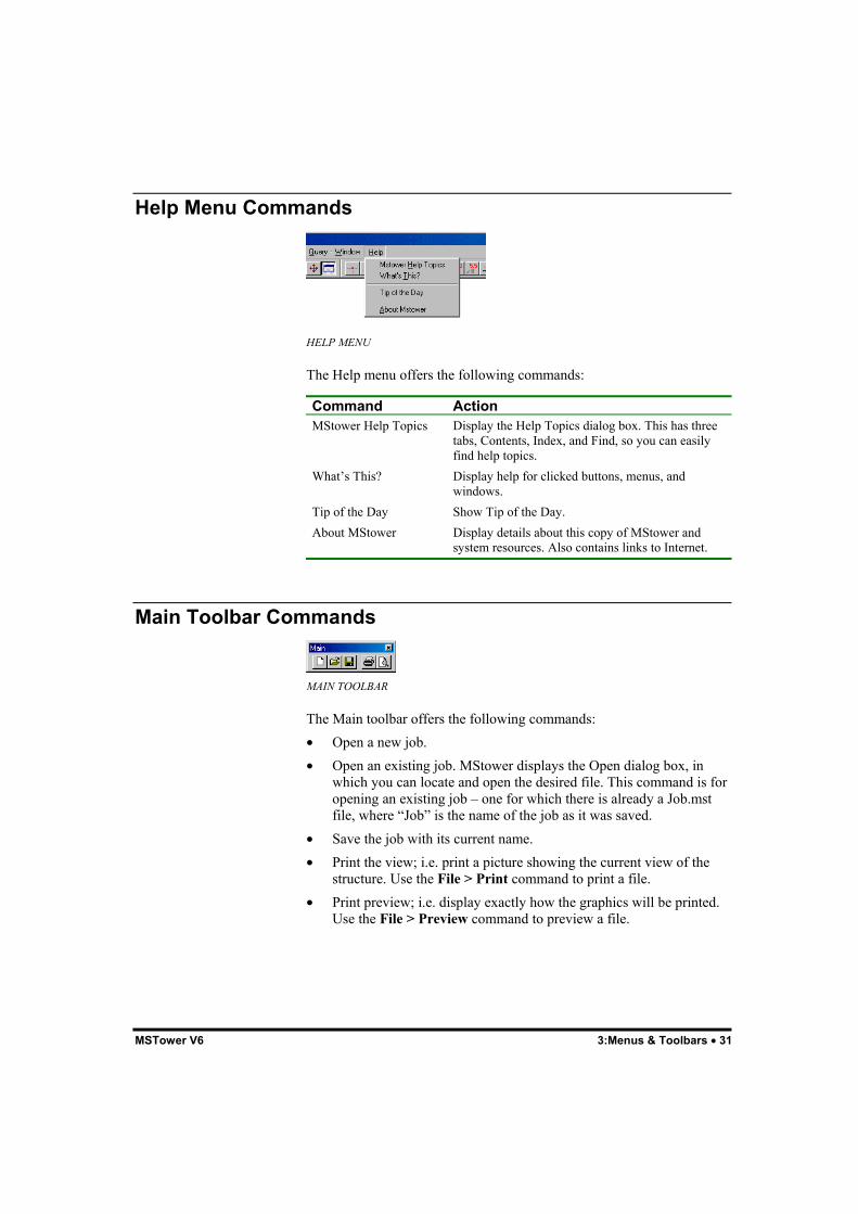
HELP MENU
The Help menu offers the following commands:
Command ActionMStower Help Topics Display the Help Topics dialog box. This has three
tabs, Contents, Index, and Find, so you can easilyfind help topics.
What’s This? Display help for clicked buttons, menus, andwindows.
Tip of the Day Show Tip of the Day.About MStower Display details about this copy of MStower and
system resources. Also contains links to Internet.
Main Toolbar Commands
MAIN TOOLBAR
The Main toolbar offers the following commands:• Open a new job.• Open an existing job. MStower displays the Open dialog box, in
which you can locate and open the desired file. This command is foropening an existing job – one for which there is already a Job.mstfile, where “Job” is the name of the job as it was saved.
• Save the job with its current name.• Print the view; i.e. print a picture showing the current view of the
structure. Use the File > Print command to print a file.• Print preview; i.e. display exactly how the graphics will be printed.
Use the File > Preview command to preview a file.

32 • 3:Menus & Toolbars MSTower V6
View Toolbar Commands
VIEW TOOLBAR
The View toolbar offers the following commands:• Display front view.• Display right view.• Display top view.• Display oblique view.• Move viewpoint to left.• Move viewpoint to right.• Move viewpoint up.• Move viewpoint down.• Zoom to extents/limits of structure. If the View > Limit command is
in effect, clicking this button alternately displays the full structureand the limited part of the structure.
• Zoom to selected window.• Zoom in.• Zoom out.• Dynamically zoom view.• Dynamically rotate view.• Pan.• Limit > Window command.• Full View command.• Show the Output window.

MSTower V6 3:Menus & Toolbars • 33
Display Toolbar Commands
DISPLAY TOOLBAR
The Display toolbar offers the following commands:• Display node symbols.• Display of node numbers.• Display member numbers.• Display section numbers.• Display supports.• Display pins.• Display rendered view of members.• Display annotation of loads.• Display annotation of member force or displacement diagrams.• Increase scale for plotting loads, member forces, or displaced shape.• Decrease scale for plotting loads, member forces, or displaced
shape.
Help Toolbar Commands
HELP TOOLBAR
The Help toolbar offers the following commands:• Help Topics. Starts HTML Help providing access to on-line help
with display of User Manual contents, index, and search facility.• Help About MStower. MStower version and licence details –
includes links to internet.

34 • 3:Menus & Toolbars MSTower V6
Draw Toolbar Commands
DRAW TOOLBAR
The Draw toolbar is available during graphical input of UDPs only. Itoffers the following commands:• Draw members.• Erase members.• Move members.• Copy members.• Reflect members.• Sub-divide members.• Rotate members.• Display grid points and set Grid snap mode.• Set Middle/End snap mode.• Set Intersection snap mode.
Attributes Toolbar Commands
ATTRIBUTES TOOLBAR
The Attributes toolbar offers the following commands:• Input section numbers.• Input member releases.• Input member orientation reference node/axis.

MSTower V6 3:Menus & Toolbars • 35
Results Toolbar Commands
RESULTS TOOLBAR
The Results toolbar offers the following commands:• Display undisplaced structure.• Select load cases for display.• Display applied loads.• Display member actions. You must turn on this “switch” before you
are able to select member forces for display.• Display axial force, Fx.• Display shear force, Fy.• Display shear force, Fz.• Display torque, Mx.• Display bending moment, My.• Display bending moment, Mz.• Display displaced structure.• Display natural vibration modes.• Display buckling modes.• Display design ratios. Design ratios are displayed graphically with
different colors representing distinct ranges of values for thepercentage of code capacity. For example, members shown brightred are loaded in excess of 110% of the design code capacity.
• Display member force envelope.• Animate modes (natural or buckling). Each mode is displayed in
turn. Press the space bar to move to the next mode or Escape to exitmode animation.
OK/Cancel Toolbar Commands
OK/CANCEL TOOLBAR
The OK/Cancel toolbar is an alternative to the context menu forconfirming or cancelling selections. Display or hide it with the View >Toolbars command. This toolbar is not displayed initially.

36 • 3:Menus & Toolbars MSTower V6
Extra Buttons Toolbar Commands
EXTRA BUTTONS TOOLBAR
The Extra Buttons toolbar contains a number of buttons that may beadded to other toolbars during customization. It is not displayed initially.The buttons available are:• Display back view.• Display left view.• Display y axis for all members.• Polar copy.• Intersect members.• Insert node.• Redraw (F5).
Selecting Which Toolbars Are DisplayedYou may easily determine the toolbars that are displayed with the View> Toolbars command. This displays the dialog box shown below. Allchecked toolbars are displayed.
TOOLBARS DIALOG BOX
Any toolbar that has been customized may be reset to the originalconfiguration by selecting it and then clicking the Reset button.

MSTower V6 3:Menus & Toolbars • 37
Customizing ToolbarsAs well as being dockable, toolbars in MStower are customizable in twoways.Firstly, while pressing the Alt key you may drag any button to anyposition on the same or another toolbar. If you drag a button to a newposition not on a toolbar, it will disappear.Secondly, you may click the Customize button in the Toolbars dialogbox (View > Toolbars command). This displays the Customize propertysheet. Clicking the New button creates a new empty toolbar with anyspecified name. On the Commands tab you may now select any existingtoolbar and drag its buttons onto the new toolbar (or any other toolbar).
CUSTOMIZING TOOLBARS
The Ouput WindowThe Output window, normally at the bottom of the main window, isdockable. You may click on any part of the edge of the Output windowand drag it, so that it floats inside the main window or docks on any edgeof the main window. You may double-click on the title bar of the floatingOutput window and it will return to its previous docked position. Clickthe Output Window button to hide or display the Output window.

38 • 3:Menus & Toolbars MSTower V6

MSTower V6 4:Operation • 39
4:Operation
Data FilesThe tower is described in data files by the minimum number of keydimensions and a description of the types of panel in the tower. Paneltypes are described by mnemonics of one to four characters. Panels maybe selected from a set of built-in face, plan, hip, and cross-arm patternsor may be defined by the user.The following data files are used:• Job.td
The tower data file.• Job.udp
An optional file containing the description of non-standard or user-defined panels.
• Job.twrThe tower loading file.
When a job is saved the above files and others associated with the jobare copied into the job.mst file.It may be convenient to copy the data files from an existing MStower joband edit these, rather than creating them from the beginning. This maybe done by opening the existing job and selecting the File > Save CopyAs command to create the new job.The data files are text files, usually created and edited with the built-intext editor, MsEdit. Data is set out in blocks identified by keywords.Blank lines may be used as required to improve the readability of thefile. The “$” character may be used to introduce comments; the “$”character and all text following on that line are ignored as input data.Individual items of data may be separated by one or more blank spaces.Each line of data must be no longer than 80 characters.

40 • 4:Operation MSTower V6
The following conventions are used to describe the input data:Square brackets are used to indicate optional data items. A and B maybe omitted in this example:...[ A ] [ B ]...
Braces are used to indicate where a choice must be made from a list ofitems. Items may be shown vertically, or horizontally when separated byvertical bars. For example:...{ item 1 }... { item 2 } { item 3 }
or...{ item 1 | item 2 | item3 }...
One of the items must be chosen.An ellipsis, “…”, indicates that the data description in this manual iscontinued on the next line. Unless otherwise noted, the data in the filemust be on one line.Two dots, “..”, are used to indicate that there is a range of valuesbetween those shown, or that a series continues.The “&” character at the end of a line indicates that the data continues onthe next line.
Note: Square brackets, braces, the vertical line symbol, and the ellipsisare used to specify input – these characters do not appear in MStowerdata files.
UnitsMStower accepts two sets of units:• Metric – using meters, kilonewtons, tonnes, and degrees Celsius,
with some data items being input and/or reported in the morecustomary units of mm and kg.
• US – using feet, kips, kip.sec2/ft, and degrees Fahrenheit, with somedata items being input and/or reported in the more customary unitsof inches and pounds.
Entries in the ancillary and guy libraries are required in metric units.
Coordinate SystemsThe vertical axis of the tower is parallel to the global Z axis. The X andY axis of the tower lie in the horizontal plane and do not need to bealigned with the geographic north. The X axis is always normal (in plan)to one face of the tower.Each member in MStower has its own set of member or local axes. Thelocal x axis is aligned along the member while the local y and z axescorrespond to the rectangular section axes. The reference node or axisdefines the plane of the local y axis.

MSTower V6 4:Operation • 41
SectionsAll sections in the tower must be described in an MStower sectionlibrary file. Dimensions and properties are automatically extracted tocompute surface and projected areas when calculating ice and wind loadsand for determining member capacities.
Member CheckingYou must ensure that wind velocities and other factors used to computeloads are consistent with the code method chosen to check memberstrengths.BS 8100 Part 3, AS 3995, ASCE10, TIA-222-G, and IS-802 are limitstates codes, whereas EIA/TIA-222-F uses permissible stresses.
Export to Microstran Archive FileThe MStower model may be exported to a Microstran archive file. Thispermits running of the model in the Microstran frame analysis anddesign program.
ErrorsAfter assembly of the tower, MStower checks for the followingconditions:Overlaid Members and Unconnected NodesThese occur when a node is coincident with a member but not connectedto it. When this occurs it is usually at the junction between panels andhappens either because a horizontal has not been deleted or because ofan incompatibility between panels. For example if a PL1 plan brace isused with an X face brace the PB1 member will overlay the H1 member.The duplicated member will not be detected by the assembly processbecause of the mid-side node in PB1. A list of such members will bedisplayed.Floating MembersThese are members that are not connected to the structure. If notremoved they will result in errors during analysis. They can result ifmembers are deleted; for example if PL1 plan bracing is used with XOface bracing and the PB1 member is deleted, the internal plan bracingmembers will not be connected to the tower. A list of such members willbe displayed.You may readily locate overlaid and floating members using MStowerscreen plots. Select the Show > Members command and then enter thelist of offending members. The full tower will now be displayed with thelisted members highlighted. You may zoom to inspect the membersmore closely and determine the reason for the error. The TD or UDP fileshould be modified as necessary.

42 • 4:Operation MSTower V6
Section ChecksThe tower builder does a number of sensibility checks as the tower isassembled and reports on the following:• Section usage – whether the section is used as a leg, brace, or other
type of member.• Whether the connection code is appropriate to the section type.• Whether a bolt-hole width has been specified for bolted members.
There are also preliminary range checks on the magnitude.You may inspect the above reports by clicking the Build tab on theOutput window.

MSTower V6 5:Tower Data • 43
5:Tower Data
GeneralData describing the tower geometry is entered into a free-format text filecalled Job.td, where “Job” is the job name. A prototype tower data filemay be generated by selecting the Tower > Build Tower > MakeTower Data File command. The dialog box shown below appears foryou to enter the basic geometric parameters.
GEOMETRY PARAMETERS DIALOG BOX
You may then enter details for each panel in this dialog box.
PANEL DETAILS DIALOG BOX
The resulting tower data file is shown below. It must now be customizedfor the particular tower you are modelling. The file will be displayed inthe MsEdit text editor when you select the File > List/Edit Filecommand and then choose “TD”.

44 • 5:Tower Data MSTower V6
TITL1 Test towerTITL2UNITS 1
PROFILEFACES 4WBASE 4.0000RLBAS 0.0000
PANEL 1 HT 1.000 TW 1.000 FACE X $ LEG ? BR1 ? H1 ?
PANEL 2 HT 1.000 TW 1.000 FACE X $ LEG ? BR1 ? H1 ?
PANEL 3 HT 1.000 TW 1.000 FACE X $ LEG ? BR1 ? H1 ?
PANEL 4 HT 1.000 TW 1.000 FACE X $ LEG ? BR1 ? H1 ?
END
SECTIONS LIBR P:UK IFACT 0.1 $ 1.00 1 EA200X200X16 2 EA150X150X10 3 EA100X100X8 4 EA70X70X6END
BOLTDATA $ TODO - bolt data goes here - format of bolt data: $ [ X x Y y Z z NSP nsp LJ lj ]END
END
PROTOTYPE TOWER DATA FILE
The Tower Data (TD) FileThe tower data file is organized into logical blocks:1. Title block.2. Component block.3. Profile block.4. Supports block.5. Guys block.6. Sections block.7. Material block.8. Bolts block.

MSTower V6 5:Tower Data • 45
Each block commences with a keyword identifying the block andterminates with the keyword END. The keyword EOF is used toterminate the file. Each data block is described in this chapter.
Title BlockTITL1 titl1TITL2 titl2UNITS units
where:TITL1 Keyword.titl1 First line of job title.TITL2 Keyword.titl2 Second line of job title.UNITS Keyword.units Integer value indicating system of units being used – 1 or 4.
1 = SI units.4 = US units.
Component BlockAlthough MStower provides a comprehensive range of panel types, theremay be times when you wish to define additional panel types. This blockallows you to reference a file containing panel data to be included in thetower.COMPONENT udp [file] ..END
where:udp Name (1-8 characters) of a user-defined panel.file Name of file containing the user-defined panel. It must have the
file name extension “udp”. The file must be specified only ifthe UDP file is not named after the job. UDP files may bereferenced by multiple jobs but unless named after the job willnot be saved in the MST file. The file may contain more thanone user-defined panel.

46 • 5:Tower Data MSTower V6
Profile BlockThis block provides the data used to generate the node coordinates andmember connectivity of the tower. Panels are described in order, fromthe top of the tower.The block contains descriptions of the face bracing, plan bracing, hipbracing, and cross-arms. Section property numbers may be assigned tothe various types of members in each panel; the property number for amember type need not be specified again unless there is a change. Panelwidths need to be input only at the bend points; intermediate widths willthen be interpolated automatically.PROFILE
FACES nface WBASE wbase DBASE dbase RLBAS rlbas
PANEL nn HT hpanl [TW bpanl] [scale] BOLT class nbolt [bolt_id] class nbolt [bolt_id]... [BOLTY class nbolt [bolt_id] class nbolt [bolt_id]..] FACE ftype [SPACE s1 .. ns@sm .. sn]... [F1 f1 F2 f2]... [NTR ntr] [ND nd] [NPL npl]... [D] [INV] [LEFT]... [LEG leg BR1 br1 BR2 br2 BR3 br3... H1 h1 H2 h2 R1 r1 .. R9 r9]... [LA la] [LB lb] [LC lc] [LD ld] [XDISC] [FACEY ftype [SPACE s1 .. ns@sm .. sn]... [F1 f1 F2 f2]... [NTR ntr] [ND nd] [NPL npl]... [D] [INV] [LEFT]... [LEG leg BR1 br1 BR2 br2 BR3 br3... H1 h1 H2 h2 R1 r1 .. R9 r9] [MCAP class c1 c2 c3] PLAN ptype [PB1 pb1 PB2 pb2 PB3 pb3 ..]... [F1 f1 F2 f2] [locn] [NORST list] HIP htype [NTR ntr] [ND nd] [HP1 hp1] [HP2 hp2]... [NORST list] CROSS ctype [X | Y] [SPAN span] | [SL sl | SR sr]... [RL rl] [RR rr] [CR1 cr1 CR2 cr2 ..]
PANEL ..
END
where:FACES Keyword.nface Number of faces in the tower, either 3 or 4.WBASE Keyword.wbase Base width of tower; i.e., the base width of the lowest panel.DBASE Keyword, optional, applicable to 4 sided towers only.dbase Base depth of tower; i.e., the distance between the legs at the
bottom of the tower for the face normal to the Y axis. Used togenerate rectangular towers.
RLBAS Keyword.

MSTower V6 5:Tower Data • 47
rlbas RL at tower base with respect to the ground level at the site.The nodes at the bottom of the legs will have this value as theirZ coordinate.
PANEL Keyword.nn Panel number.HT Keyword.hpanl Panel height.TW Keyword.tw Width at top of panel, for the face normal to the X axis. If not
given, this value will be interpolated.TD Keyword, optional, used for rectangular towers.tw Width of the top of the panel, for the face normal to the Y axis.
If not given, it will be interpolated.scale Optional keyword pertaining to variable dimensions F1 and F2:
FR F1 and F2 are factors; the actual dimensions are obtained bymultiplying a length as shown on the panel diagram.LE F1 and F2 are lengths.
If omitted, fractional scaling, FR is assumed.
BOLT Keyword.class Member class, one of the following member types:
LEG Leg members.BR BR1..BR4 Bracing in the face.H H1 H2 Horizontal in the face.R R1..R9 Face redundant.PB PB1..PB10 Plan bracing.HP HP1..HP10 Hip bracing.CR CR1..CR10 Cross-arm members.If a mnemonic without a numeric suffix is used, all members ofthe class will have the number of bolts specified.
nbolt The number of bolts in the end connection of the member –zero for welded connections.
You may use as many class/nbolt pairs as are necessary.

48 • 5:Tower Data MSTower V6
bolt_id Optional character string, used to identify the bolt in theBOLTDATA table.
BOLTY Keyword, optional.The data required for BOLTY is similar to that for BOLT. Usedto describe the bolting on the faces of the tower normal to the Yaxis if it differs from that on the faces normal to the X axis.
FACE Keyword.ftype Face bracing pattern type. User-defined panels must have their
names prefixed with the “@” character; e.g. @XYZ refers to auser-defined panel XYZ. UDPs may have names with amaximum of 8 characters and must have been referenced in theCOMPONENT block.
SPACE Keyword.s1..sn List of spacings for XM, DM, DLM, DRM, DMH, KXM, and
XDM type face bracing.ns@sm Shorthand way of indicating that a multiple panel has a number
of identical spacings:ns Number of identical spacings.@ Keyword.sm Value of identical spacing.
F1,F2 Keywords.f1,f2 Factors used to locate nodes for some bracing types. The use of
these factors is shown on the individual bracing diagrams.NTR,ND Keywords.ntr,nd Number of levels of triangle and diagonal braces, respectively,
in some face and hip brace patterns.NPL Keyword.npl Bracing pattern in part of a portal or cranked K face.D Keyword – used with XDM bracing.LEFT Keyword – used with DM bracing.INV Keyword, used with KB, KBP, KM, KMA, KMG, KMGA,
KMGD, KMH, KMHA, KMV, KVH3, and KVS3, indicatingthat the panel is to be inverted.
LEG Keyword.leg Section property number for leg members.BRn Keyword.brn Section property number for brace members, type n, where n is
a digit from 1 to 3.Hn Keyword.

MSTower V6 5:Tower Data • 49
hn Section property number for horizontal members, type n, wheren is a digit from 1 to 2.
Rn Keyword.rn Section property number for redundant or secondary bracing
members, type n, where n is a digit from 1 to 9.All property numbers for a particular member class may be setby using the keyword without a numeric suffix; e.g. BR will setBR1, BR2, and BR3.
LA,LB,LC,LD
Keywords.
la,lb,lc,ld
Section property numbers for leg A, B, C, and D, respectively.Leg A is in the positive X-Y quadrant and the other legs areidentified in sequence, anti-clockwise from leg A when viewedin plan. The properties of the leg members of the tower may beassigned individually if they are not symmetrical. In any case, anon-zero property must follow the LEG keyword.
XDISC Optional keyword indicating that the X bracing isdiscontinuous at the intersection point. Triangulated planbracing or a horizontal member stiff enough to provide restraintmust be provided.
FACEY Optional keyword.
The data required for FACEY is similar to that for FACE. It isused to describe the bracing on the faces of the tower normal tothe Y axis if it differs from that on the faces normal to the Xaxis.FACEY may be omitted, in which case:Square towers will have the pattern defined in FACE on allfaces.Rectangular tower will have no bracing on the Y face; the panelmust be made into a UDP and the bracing added manually.
MCAP Keyword.class Member class, as described above under BOLT.c1,c2,c3 User defined member capacity, kN or kips.
c1 Capacity of member in compression.c2 Capacity of member in tension.c3 Capacity of joint.All three capacities must be given. Code rules will be used tocompute the capacity if any of “c1 c2 c3” is entered as zero.For monopoles, c1, c2 and c3 are the compressive, flexural andtorsional capacities respectively.If members are to be checked to BS 8100 or ILETR7, a partialsafety factor for material of unity should be used whendetermining user defined capacities.

50 • 5:Tower Data MSTower V6
PLAN Keyword.ptype Plan bracing pattern type.PBn Keyword.pbn Section property number for plan bracing member, type n,
where n is a value from 1 to 10. The property numbers for allplan braces will be set to this value if the numeric suffix isomitted from the keyword.
F1,F2 Keywords.f1,f2 Factors used to locate nodes for some bracing types. The use of
these factors is shown on the individual bracing diagrams.locn Optional character string indicating the vertical location of plan
bracing in the current panel. If omitted, the plan bracing will beplaced at the top of the face panel. Must be one of:TOP Top of the face panel.BTM Bottom of the face panel. This may be required with certaininverted face panels or type “M” face bracing.XIP The level of the intersection of cross-brace members in theface.MID The mid-height of the face.
NORST Keyword.list List of integers, 1–10, giving the suffix number of members
that are to be considered as providing no buckling restraint tomain load carrying members they connect to. For example, if aplan bracing pattern such as PL3 is used, NORST 2, willindicate that the PB2 member is not to be considered asproviding restraint to the peripheral member at the mid-sidenode.
HIP Keyword.htype Hip bracing pattern type.NTR, ND Keywords.ntr, nd Number of levels of triangle and diagonal braces, respectively,
in some hip brace patterns.HPn Keyword.hpn Property number for hip bracing, type n. The property
numbers for all hip braces will be set to this value if thenumeric suffix is omitted from the keyword.
NORST Keyword.list List of integers, 1–10, giving the suffix number of members

MSTower V6 5:Tower Data • 51
that are to be considered as providing no buckling restraint tomain load carrying members they connect to.
CROSS Keyword.ctype Cross-bracing pattern type.X,Y Keywords indicating that the cross-arms are to be attached to
the X or Y faces of the tower. If not specified the cross-armswill be attached to the Y faces; i.e. they will project to the leftand right when viewed from the direction of the X axis.
SPAN Keyword.span Total span of symmetrical cross-arm. If the cross-arm is not
symmetrical, separate left-hand and right-hand “half” spansmust be specified.
SL Keyword.sl Left-hand “half” span of the cross-arm. Viewed from the
positive X axis direction if attached to the Y faces, or viewedfrom the positive Y axis direction if attached to the X faces.
SR Keyword.sr Right-hand “half” span of the cross-arm.RL Keyword.rl Rise of left-hand “half” span of the cross-arm when viewed as
described above.RR Keyword.rr Rise of right-hand “half” span of the cross-arm.CRn Keyword.crn Section property number for cross-arm member, type n, where
n is a value from 1 to 10. The property numbers for all cross-arm members will be set to this value if the numeric suffix isomitted from the keyword.
Each panel must have one set of face braces and optionally one set of hipbracing and one or two sets of plan and/or cross-arm braces.Redundant members are pin-ended. All other members are assumed tobe rigidly connected.Any member assigned a property number of zero will be deleted. Forexample an “X” face panel with H1 = 0 is identical to an “X0” panel.You must ensure that the deletion of members does not result in anunstable structure.When inverting panels, it may be necessary to delete the horizontalmember in either the inverted panel or the panel on which it is mounted,if the two horizontals are not sub-divided in identical fashion.“C” nodes (reference nodes), which define member orientation, areallocated in the plane of the face or hip for all members except H1 andH2 type members, where the “C” node is in the direction of the global

52 • 5:Tower Data MSTower V6
“Z” axis; i.e. for face members apart from H1 and H2, and hip braces,the member “y” axis lies in the plane of the hip or face. Orientationkeywords may be applied to the section definition (see “Sections Block”,below) if the section is to be rotated.If a member class mnemonic is used without a numeric suffix allmembers of the class will have the number of bolts (or membercapacities) specified. For example, if all redundants in a panel use thesame bolting, specify: BOLT R nbolt [bolt-id]Bracing patterns and the location of different member types are shownon the bracing diagrams. Some face panels, such as XTR and KTR, areshown with asymmetrical redundants. In these cases, the arrangement ofredundants on the left-hand part of the diagram applies to the X faces ofthe tower while that on the right-hand side applies to the Y faces.
Note: The number of bolts in the ends of members is used in strengthchecking modules to determine buckling curves or effective slendernessratios. If the number of bolts is not specified MStower will assume thatall members are single-bolted except for legs, face bracing, andhorizontals that are assumed to have two or more bolts. Normally, thebolt specification will be entered in the first panel; it is only necessary toenter changes (if any) in subsequent panels. The bolts themselves willnot be checked unless bolt_ids are defined in BOLT statements andbolt information is defined in a BOLTDATA block.

MSTower V6 5:Tower Data • 53
Supports BlockThis block is optional and may be used to modify the default supportconditions of full fixity for all supports except for masts where the legsjoin at a single pinned support point.SUPPORTS {COORD x y z | LEG abcd}... {PINNED|FIXED [BUT {releases|springs}]} ..END
where:COORD Keyword.x y z Coordinates of a node that is to be restrained.LEG Keyword.abcd Leg number in the form of a compact list using the characters
A, B, C, or D. Leg A is in the positive X-Y quadrant. The otherlegs are identified in sequence, anti-clockwise from leg A whenviewed in plan; e.g. AC would indicate that the supportconditions apply to legs A and C.
PINNED Keyword indicating that the node is pinned; i.e., it is free torotate but all translational degrees of freedom are restrained.
FIXED Keyword indicating that the node is completely fixed; i.e., alldegrees of freedom are restrained.
BUT Keyword used with FIXED to indicate that some degrees offreedom are to be released or have spring restraints.
releases List of degrees of freedom to be released. One or more of:FX FY FZ MX MY MZ
springs List of degrees of freedom that are to be restrained by springs,with the corresponding spring constant. One or more of thefollowing pairs:KFX kfx KFY kfy KFZ kfz KMX kmxKMY kmy KMZ kmz

54 • 5:Tower Data MSTower V6
Guys BlockThis block pertains to guyed masts only and is used to specify the librarycontaining the properties of guy wires and their arrangement on the mast.GUYS LIB lib XB xb YB yb ZB zb XT xt YT yt Zt zt NO no ANGL angl... TO to KT kt LIB guy_idEND
where:LIB Keyword.lib Name of library containing guy data. It is assumed that the
library is located in the data folder unless the name is prefixedwith “P:” or “L:”. “P:” indicates that the library is in theprogram folder and “L:” indicates that it is in the library folder.
XB Keyword.xb Global X coordinate of the lower end of the guy.YB Keyword.yb Global Y coordinate of the lower end of the guy.ZB Keyword.zb Global Z coordinate of the lower end of the guy.XT Keyword.xb Global X coordinate of the upper end of the guy.YT Keyword.yb Global Y coordinate of the upper end of the guy.ZT Keyword.zb Global Z coordinate of the upper end of the guy.NO Keyword.no Number of guys in this group.ANGL Keyword.angl Angle between successive guys in the group, in degrees.TO Keyword.to Initial guy tension, in kN or kips. The unstrained length of the
guy will be adjusted so that when stretched between theundisplaced end nodes, the maximum tension in the guy willequal this value. The still air tension will be less than the initialtension due to the elastic shortening of the shaft of the mast.Some trial-and-error adjustments of TO values may benecessary to obtain the required still-air tensions.
KT Keyword.kt Guy connection efficiency factor.LIB Keyword.guy_id Character string of 1 to 16 characters used to identify the guy in
the guy library. The properties of the guy required for analysis

MSTower V6 5:Tower Data • 55
and design will be taken from the guy library.
The first guy in the group will span between (xb, yb, zb) and (xt, yt, zt),and if no is greater than 1, additional cables will be automaticallygenerated at an angular increment of angl anti-clockwise about thevertical axis of the mast. Guys can be generated only where they areradially symmetrical about the vertical axis of the mast. For example,guys that have their anchor points at different levels because of a slopingsite have to be input singly.Usually, guys are input as single members. A guy may also be input as anumber of segments to accommodate changes in properties or to allowan insulator to be positioned along its length. In this case, you shouldinput the segments of guy sequentially, commencing at the anchor pointand working up to the mast shaft with the coordinates of the lower endof one segment being set equal to those of the upper end of the precedingsegment. The segments of guy may be generated as described above.
Sections BlockThis block specifies the section library and nominates the section to beused for each section property number.SECTIONS LIBR libr IFACT fact n sname [X|Y] [CONNECT con] [BH bh] [FY fy] [FU fu] ..END
where:LIBR Keyword.libr Name of library containing section data. It is assumed that the
library is located in the data folder unless the name is prefixedwith “P:” or “L:”. “P:” indicates that the library is in theprogram folder and “L:” indicates that it is in the library folder.
IFACT Keyword.fact Factor by which the section Ixx and Iyy will be multiplied on
extraction from the library. When you specify a low value thetower will approach the condition of a space truss with pin-ended members. This is convenient for analysing as a spaceframe, with sufficient continuity across the joints to avoidmathematical instabilities due to coplanar nodes, but withoutgenerating significant bending moments.
n Section property number.sname Name of library section.X Y Keywords used to indicate the orientation of the section with
respect to the member y axis:X The section XX axis is aligned with the member y axis.Y The section YY axis is aligned with the member y axis.Use of these keywords will allow you to correctly orient

56 • 5:Tower Data MSTower V6
asymmetrical sections. For example, if an unequal angle is usedin the face of the tower, orientation Y will result in the long legof the angle being parallel to the face, whereas orientation Xwill result in the long leg being normal to the face of the tower.Note that the member y axis is not altered by the use of anorientation keyword. See diagram below.
CONNECT Keyword.con Single-character mnemonic indicating the connected element of
the section:C Concentrically connected (default).L Long leg of angle.S Short leg of angle.F Flange of I, H, or T section.W Web of I, H, or T section.The following codes are applicable to braces of solid rod ortubular section to allow K factors to be determined inaccordance with BS 8100 Part 3 Table 3:
SG The member is attached to a gusset plate that is not shared with other members.MG The member is attached to a gusset plate that is shared with other members.CR Continuous solid rod bent in the form of a “W” welded to the tower legs.It is important that you specify the connected element for eachsection. If omitted, MStower assumes the member isconcentrically connected, giving a higher strength than it mayactually have.
BH Keyword.bh Effective width of bolt holes, in mm or inches, in the connected
element, taking into account any staggering of holes,FY Keyword.fy Yield stress of the section. It may be either a numerical value,
in N/mm2 (MPa) or Kips/in2, or, a single-character mnemonicindicating the yield strength to be taken from the sectionlibrary:N Normal yield stress (default).H High yield stress.
N and H yield strengths correspond to the “y1” and “y2” yieldstrengths in the MStower section libraries. In UK libraries,these will normally be based on Grade 275 and Grade 355 steel,respectively. Generally, it is recommended that you use explicitnumerical values for “fy”.
FU Keyword.fu Ultimate tensile strength. Derived from fy if not specified.

MSTower V6 5:Tower Data • 57
Note: MStower models members as three-dimensional beam-columns.If the default, IFACT 1, is used the second moments of area computedfrom the dimensions of the section will be used to determine the flexuralstiffness of a member. A lower value of IFACT may be used to reducethe bending stiffness of members so that the analysis approaches that ofa space truss but without the necessity of adding dummy members orsprings to stabilize unstable nodes. The typically small bending momentsfound in triangulated towers will be reduced and the behaviour of themodel will more closely approximate that of a space truss.If flexural stiffness is important “IFACT 1” should be used. This appliesto structures that are not fully triangulated or where a second-orderanalysis or an elastic critical load analysis is required.
The orientation of the section is the cross-section axis (XX or YY) that iscoincident with the member y axis (see diagram below).
ORIENTATION OF SECTION

58 • 5:Tower Data MSTower V6
Material BlockThis block is optional. It is used to change the default values of thematerial used for the tower or the shaft of a mast.MATERIAL E e PR pr DENS dens ALPHA alphaEND
where:E Keyword.e Young’s modulus (2.05×10⁵ N/mm2 or 29000 kips/in2).PR Keyword.pr Poisson’s ratio (0.3).DENS Keyword.dens Mass density (7850 kg/m3 or 490 lb/ft3).ALPHA Keyword.alpha Coefficient of thermal expansion (12.0×10⁻⁶ per °C or 5.9×10⁻⁶
per °F).
The default material properties are shown above in brackets.
Note: Material properties for guys are obtained from the specified guylibrary.
Bolt Data BlockThis block specifies bolt diameters, grades, and other data required inchecking the capacity of bolted end connections.BOLTDATA bolt_id grade D d AS as FY fy FU fu FV fv... [FV_EIA fv_eia | FV_ASCE fv_asce | FV_TIA fv_tia]... [X x] [Y y] [Zz z] [NSP nsp] [LJ lj]... [FYP fyp FUP fup TP tp]... [TENS AT at FT ft PR pr] ..END
where:bolt_id String of 1 to 8 characters used to identify the bolt type in the
BOLT statement in the PANEL data above.grade Bolt grade description, e.g. “GR8.8”. The string has no
significance to the program.D Keyword.d Nominal bolt diameter, in mm or inches.AS Keyword.

MSTower V6 5:Tower Data • 59
as Cross-sectional area of the bolt effective in shear, in mm2 orin2.
FY Keyword.fy Yield stress of bolt, in N/mm2 (MPa) or kips/in2.FU Keyword.fu Ultimate tensile stress of bolt, in N/mm2 (MPa) or kips/in2.FV Keyword.fv Shear strength of bolt, in N/mm2 (MPa) or kips/in2, used when
checking bolts to AS 3995; capacities to this code are strengthlimit state.
FV_EIA Keyword.fv_eia Shear strength of bolt, in N/mm2 (MPa) or kips/in2, used when
checking the capacity of bolted joints to EIA-222-F; capacitiesto this code are based on working stress.
FV_ASCE Keyword.fv_asce Shear strength of bolt, in N/mm2 (MPa) or kips/in2, used when
checking the capacity of bolted joints to ASCE 10-90;capacities to this code are for the strength limit state.
FV_TIA Keyword.fv_tia Shear strength of bolt. If defined, the shear capacity of the bolt
is (φb fv_tia As), otherwise the capacity is computed as(φb 0.4 fu As), assuming threads included in the shear plane.
X Keyword.x Distance between end of the member and first bolt parallel to
the axis of the member, in mm or in. If omitted, the memberchecking program assumes that code requirements are met.
Y Keyword.y Distance between line of bolts and edge of member at right
angles to the axis of the member, in mm or in. If omitted, themember checking program assumes that code requirements aremet.
Z Keyword.z Spacing between bolts parallel to the axis of the member, in
mm or in. If omitted, the member checking program assumesthat code requirements are met..
NSP Keyword.nsp Number of shear planes. This value needs to be specified only
if the number of shear planes in the bolted joint differs from thedefault values used in the member checking modules. Bolts areassumed to have a single shear plane for all sections exceptcompound sections, DAL, DAS, CBB, and QAN, where thebolts are in double shear.
LJ Keyword.lj Length of the line of bolts in the joint, in mm or in. This value

60 • 5:Tower Data MSTower V6
is required only for codes that reduce the strength of longjoints. If omitted, the strength will not be reduced.
FYP Keyword.fyp Yield strength of plies to be used in checking bearing capacity
of joint. If omitted, the yield strength of the member materialwill be used.
FUP Keyword.fup UTS of plies to be used in checking joints. Derived from fy if
not specified.TP Keyword.tp Thickness of plies to be used in checking bearing capacity of
joint. If omitted, a thickness obtained from the member sectiondimensions will be used.
TENS Keyword indicating that the joint is a flanged joint, wheretensile forces are carried by direct tension in the bolts andcompression by direct end bearing. If omitted, the joint will bechecked as a shear type.
AT Keyword.at Cross-sectional area of the bolt effective in tension, in mm2 or
in2
FT Keyword.ft Tensile strength of the bolt, in N/mm2 or kips/in2 to be used
when checking the tensile capacity of the joint. If omitted, acode-dependent fraction of the ultimate tensile strength of thebolt will be used.
PR Keyword.pr Prying factor to take account of the increase in the bolt tension
caused by prying action in the joint. The nominal capacity ofthe bolt subject to prying is taken as (at × ft / pr). If omitted, afactor of 1.0 will be used, i.e. the joint is not subject to prying,requiring relatively thick flanges.
Bolted joint capacities can be checked only in conjunction with amember check. This has been implemented for all codes other thanBS 449.Shear type joints are checked for shear on the bolts and bearing on boltsand plies. No checks are carried out on the strength of gusset plates, sothese must be separately considered. In particular, it is important that thecompression capacity of overlapped gusset plates or “eccentricallyconnected cleats” should be checked. These often occur where hollowsection compression members are connected to a gusset plate.In tension joints the bolts are checked for the applied forces plusspecified prying – flange plates and welds are not checked.A bolt data file called Bolts is included in the program folder. You maycopy its contents to TD files using Copy and Paste commands in MsEdit.

MSTower V6 5:Tower Data • 61
Guy LibraryThe guy library is a text file containing data giving the dimensions andstructural characteristics of wire ropes used as guys. The guy librarysupplied with MStower is MS_Guy.lib, which may be modified ifrequired.The structure of the guy library file is:GUYS guy-id d m ac e alpha fu ntype ..END
where:GUYS Keyword.guy-id String of 1 to 16 characters used to identify the guy ropes.d Diameter of guy rope, mm.m Mass per unit length, kg/m.ac Effective cross-sectional area, mm2.e Modulus of elasticity, N/mm2.alpha Coefficient of thermal expansion, per °C.fu Ultimate tensile stress, N/mm2.ntype Guy type, based on Table 4.1 of BS 8100 Part 1:
1. T4.1(b) Circular sections and smooth wire.2. T4.1(c) Fine strand cable.3. T4.1(d) Thick strand cable.
Note: The guy library uses metric units.

62 • 5:Tower Data MSTower V6
Steel PolesA steel pole may be input using the following menu command:Tower >
Build Tower >Make Tower Data File >
Steel Pole DataIn the Steel Pole Data dialog box you may choose parameters to definethe pole. Permitted shapes include circular, square, or polygonal sectionswith 8, 12, 16, or 20 sides. Each panel is assumed to be a single length ofcircular cylinder or a tapered tube made up of a single width of steelplate. These panels will be further sub-divided before output to the towerdata file.
STEEL POLE DATA DIALOG BOX
Note: Not all pole shapes available in MStower are covered by thevarious codes that deal with poles.
In the next dialog box, data is input for each panel starting at the top ofthe pole. You may change panel heights, plate thicknesses, and yieldstrengths. Diameters have to be entered for the top of the pole and atbend points only. All other diameters are interpolated by MStower.
STEEL POLE PANEL DATA DIALOG BOX

MSTower V6 5:Tower Data • 63
Once the data has been accepted MStower generates a TD file completewith a SECTION block and a section library for the pole. The menucommand:Tower >
Build Tower >Edit Tower Data
may be selected to inspect the generated data file. Note that for poles“FACES 1” is specified in the TD file.The TD file for a tapered pole made up of two 6m high pieces is shownbelow:
TITL1 Pole ExampleTITL2
UNITS 1PROFILEFACES 1
WBASE 0.600RLBAS 0.000PANEL 1 HT 0.6000 TW 0.6000 FACE SH1 LEG 1 R1 22PANEL 2 HT 0.6000 TW 0.6000 FACE SH1 LEG 2 R1 22PANEL 3 HT 0.6000 TW 0.6000 FACE SH1 LEG 3 R1 22PANEL 4 HT 0.6000 TW 0.6000 FACE SH1 LEG 4 R1 22PANEL 5 HT 0.6000 TW 0.6000 FACE SH1 LEG 5 R1 22PANEL 6 HT 0.6000 TW 0.6000 FACE SH1 LEG 6 R1 22PANEL 7 HT 0.6000 TW 0.6000 FACE SH1 LEG 7 R1 22PANEL 8 HT 0.6000 TW 0.6000 FACE SH1 LEG 8 R1 22PANEL 9 HT 0.6000 TW 0.6000 FACE SH1 LEG 9 R1 22PANEL 10 HT 0.6000 TW 0.6000 FACE SH1 LEG 10 R1 22PANEL 11 HT 0.6000 TW 0.6000 FACE SH1 LEG 11 R1 22PANEL 12 HT 0.6000 TW 0.6000 FACE SH1 LEG 12 R1 22PANEL 13 HT 0.6000 TW 0.6000 FACE SH1 LEG 13 R1 22PANEL 14 HT 0.6000 TW 0.6000 FACE SH1 LEG 14 R1 22PANEL 15 HT 0.6000 TW 0.6000 FACE SH1 LEG 15 R1 22PANEL 16 HT 0.6000 TW 0.6000 FACE SH1 LEG 16 R1 22PANEL 17 HT 0.6000 TW 0.6000 FACE SH1 LEG 17 R1 22PANEL 18 HT 0.6000 TW 0.6000 FACE SH1 LEG 18 R1 22PANEL 19 HT 0.6000 TW 0.6000

64 • 5:Tower Data MSTower V6
FACE SH1 LEG 19 R1 22PANEL 20 HT 0.6000 TW 0.6000 FACE SH1 LEG 20 R1 22PANEL 21 HT 0.0000 TW 0.6000 FACE SH1 LEG 21 R1 22ENDSECTIONS LIB Ex_Pole 1 C1.600x12 FY 250.00 2 C2.600x12 FY 250.00 3 C3.600x12 FY 250.00 4 C4.600x12 FY 250.00 5 C5.600x12 FY 250.00 6 C6.600x12 FY 250.00 7 C7.600x12 FY 250.00 8 C8.600x12 FY 250.00 9 C9.600x12 FY 250.00 10 C10.600x12 FY 250.00 11 C11.600x12 FY 250.00 12 C12.600x12 FY 250.00 13 C13.600x12 FY 250.00 14 C14.600x12 FY 250.00 15 C15.600x12 FY 250.00 16 C16.600x12 FY 250.00 17 C17.600x12 FY 250.00 18 C18.600x12 FY 250.00 19 C19.600x12 FY 250.00 20 C20.600x12 FY 250.00 21 C21.600x12 FY 250.00 22 DUMMY FY 250.00END
SUPPORT COORD 0.0 0.0 0.0 FIXEDEND
EOF
TD FILE FOR STEEL POLE
Each segment is modelled as a FACE SH1 panel. The SH1 panelconsists of an axial shaft (leg) member with three radial dummymembers at the top that locate nodes on the surface of the pole. Thesenodes are rigidly connected to the node on the axis of the pole by master-slave constraints. The purpose of the surface nodes is to facilitate theattachment of ancillaries to the pole.A SECTIONS block has also been generated. Each segment of a taperedpole will be represented by a separate section. The name of each sectiongives an indication of its shape, location, and thickness. A section libraryis automatically generated and compiled.Step changes in pole diameter may be allowed for by inserting a conicalmember of small height in the panel data dialog box. This segment maysubsequently be edited from the TD file.

MSTower V6 5:Tower Data • 65
Poles may also be input directly with the text editor. There should be alarge enough number of panels to accurately represent the wind load,which is modelled by node forces applied to the axial nodes.
TD File Examples
Example 1The example below shows the TD file statements required to generate apyramidal face panel with two sets of cross-arms.
PANEL 1 HT 1.372 TW 0 FACE X0 LEG 1 H1 0 BR1 0 CROSS CT SPAN 6 RISE 7 CR1 10 CR2 12 CROSS CT SPAN 8
PANEL 2 HT 3.13 TW 1.6 FACE XDM SPACE .788 .787 .788 .787 D LEG 1 H1 2 BR1 2
PANEL 3 HT 1.575 FACE XDM SPACE .788 .787 D CROSS CT1 SPAN 8.32 CR1 10 CR2 12 CR3 15 CR4 16
CROSS ARM EXAMPLE

66 • 5:Tower Data MSTower V6
Example 2A square tower with different bracing patterns on the X and Y faces iscreated in the example below. The legs of the tower are sub-dividedautomatically to suit the bracing. Only members at the front arerendered.
PROFILEFACES 4WBASE 4.0RLBAS 0.0
PANEL 1 HT 3.5 TW 3 FACE K1 FACEY K2END
SQUARE TOWER EXAMPLE

MSTower V6 5:Tower Data • 67
Example 3This example shows a rectangular tower with different bracing patternson the X and Y faces. Only members at the front are rendered.
PROFILEFACES 4WBASE 4.0DBASE 3.0RLBAS 0.0
PANEL 1 HT 6 TW 3.5 TD 2.5 BOLT BR1 3 FACE XO LEG 1 BR1 2 BOLTY BR1 4 FACEY K1 H1 0 BR1 3 PLAN PL2END
RECTANGULAR TOWER EXAMPLE

68 • 5:Tower Data MSTower V6
Example 4The example below is a single circuit tower; the upper part of the toweris rectangular while the lower section is square. The upper panels do nothave bracing defined for the Y faces and are thus incomplete. They mustbe converted to UDPs and edited graphically.
PROFILEFACES 4WBASE 8.0DBASE 8.0RLBAS 0.0
PANEL 1 HT 3.0 TW 18.0 TD 0.0 FACE KMGD ND 2 F1 0.667 INVPANEL 2 HT 2.0 TW 14.0 TD 1.0 FACE SCBR F1 0.667 F2 0.667 CROSS CT1 SPAN 22.0 CR1 1 CR2 2 CR3 3PANEL 3 HT 7.5 TW 14.0 TD 1.0 FACE KMGD ND 2 F1 0.667PANEL 4 HT 6.5 FACE XM23 INVPANEL 5 HT 3.25 TW 4.0 TD 4 $ square below here FACE XTR F1 0.5 PLAN PL2APANEL 6 HT 3.25 $ TW is interpolated FACE M1PANEL 8 HT 3.25 FACE K1END
SINGLE CIRCUIT TOWER EXAMPLE

MSTower V6 5:Tower Data • 69
Note: In computing the transverse wind load on the V section of singlecircuit towers MStower considers the solidity of the outside faces of thearms of the V; the bracing on the inside faces of the arms is considered“internal to the tower” and is not considered.You should assess any additional wind loads on this section of the towerand add them to the WL cases as NDLDs.

70 • 5:Tower Data MSTower V6
Example 5 (Plan Bracing)Plan bracing is located as shown.
LOCATION OF PLAN BRACING
This example shows part of a tower with plan bracing at the top and atthe level of the X bracing intersection points. Only the members formingthe plan bracing are rendered.
PROFILEFACES 4WBASE 4.0DBASE 4.0RLBAS 0.0
PANEL 1 HT 6 TW 3.5 TD 3.5 BOLT BR1 3 FACE XO LEG 1 BR1 2 BOLTY BR1 4 FACEY XO H1 0 BR1 3 PLAN PL2 TOP PLAN PLX XIPEND
PLAN BRACING EXAMPLE

MSTower V6 6:Standard Panels • 71
6:Standard Panels
GeneralThis chapter shows the standard panels available in MStower. Many ofthese have been included to assist in modelling existing towers or to givethe starting geometry for making a UDP. The inclusion of any particularpanel pattern should not be construed as a recommendation for its use.

72 • 6:Standard Panels MSTower V6
Index – Face Panels

MSTower V6 6:Standard Panels • 73

74 • 6:Standard Panels MSTower V6

MSTower V6 6:Standard Panels • 75

76 • 6:Standard Panels MSTower V6
Index – Plan Bracing
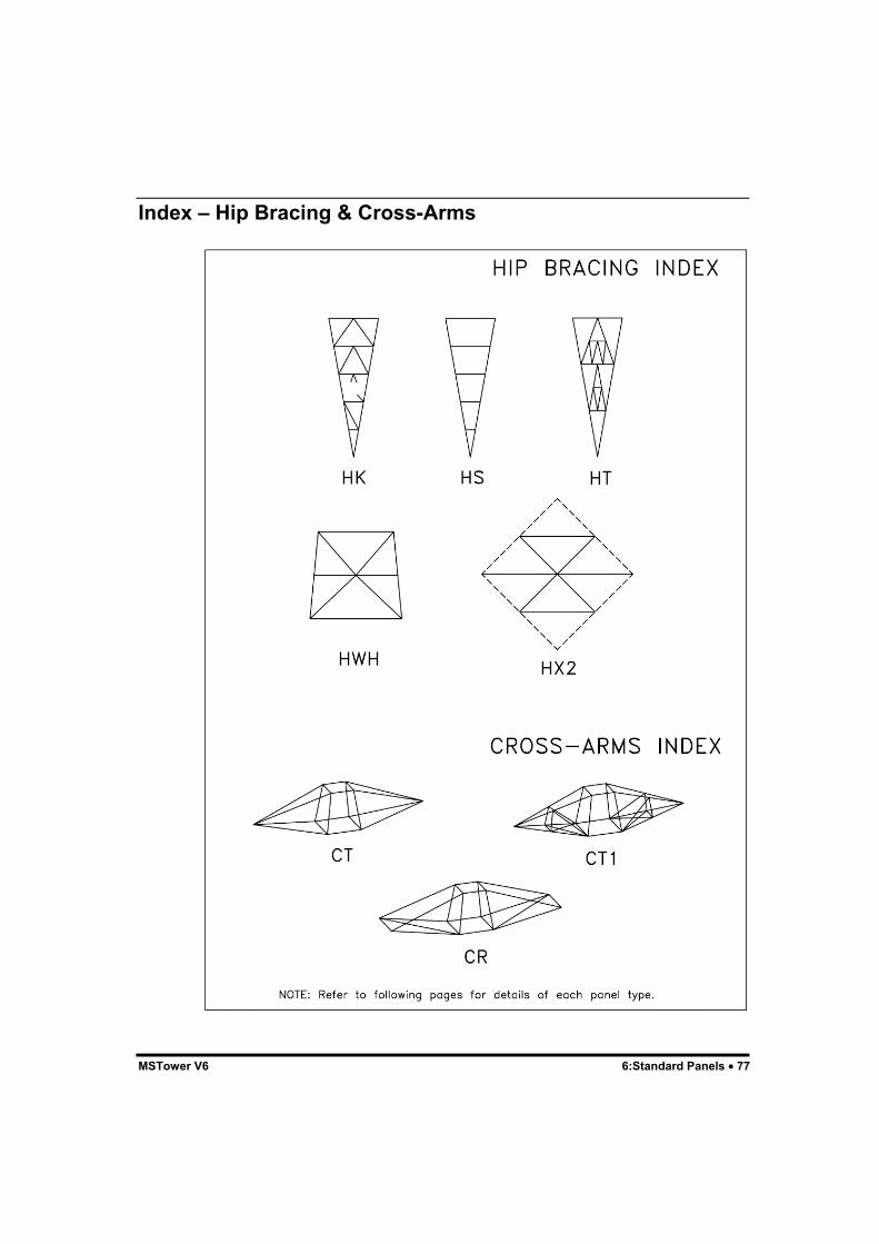
MSTower V6 6:Standard Panels • 77
Index – Hip Bracing & Cross-Arms

78 • 6:Standard Panels MSTower V6
D & V Face Panels

MSTower V6 6:Standard Panels • 79
X Face Panels

80 • 6:Standard Panels MSTower V6

MSTower V6 6:Standard Panels • 81

82 • 6:Standard Panels MSTower V6

MSTower V6 6:Standard Panels • 83

84 • 6:Standard Panels MSTower V6
K Face Panels

MSTower V6 6:Standard Panels • 85

86 • 6:Standard Panels MSTower V6

MSTower V6 6:Standard Panels • 87

88 • 6:Standard Panels MSTower V6

MSTower V6 6:Standard Panels • 89

90 • 6:Standard Panels MSTower V6

MSTower V6 6:Standard Panels • 91

92 • 6:Standard Panels MSTower V6

MSTower V6 6:Standard Panels • 93
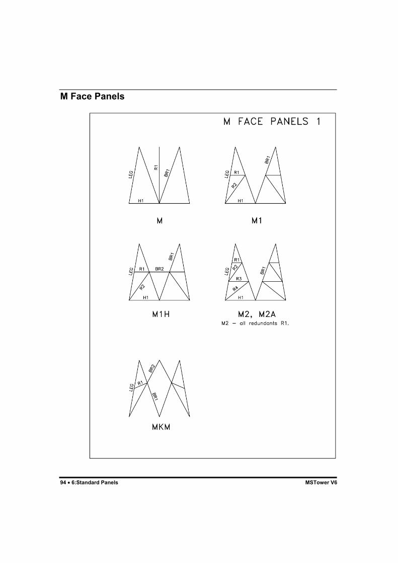
94 • 6:Standard Panels MSTower V6
M Face Panels
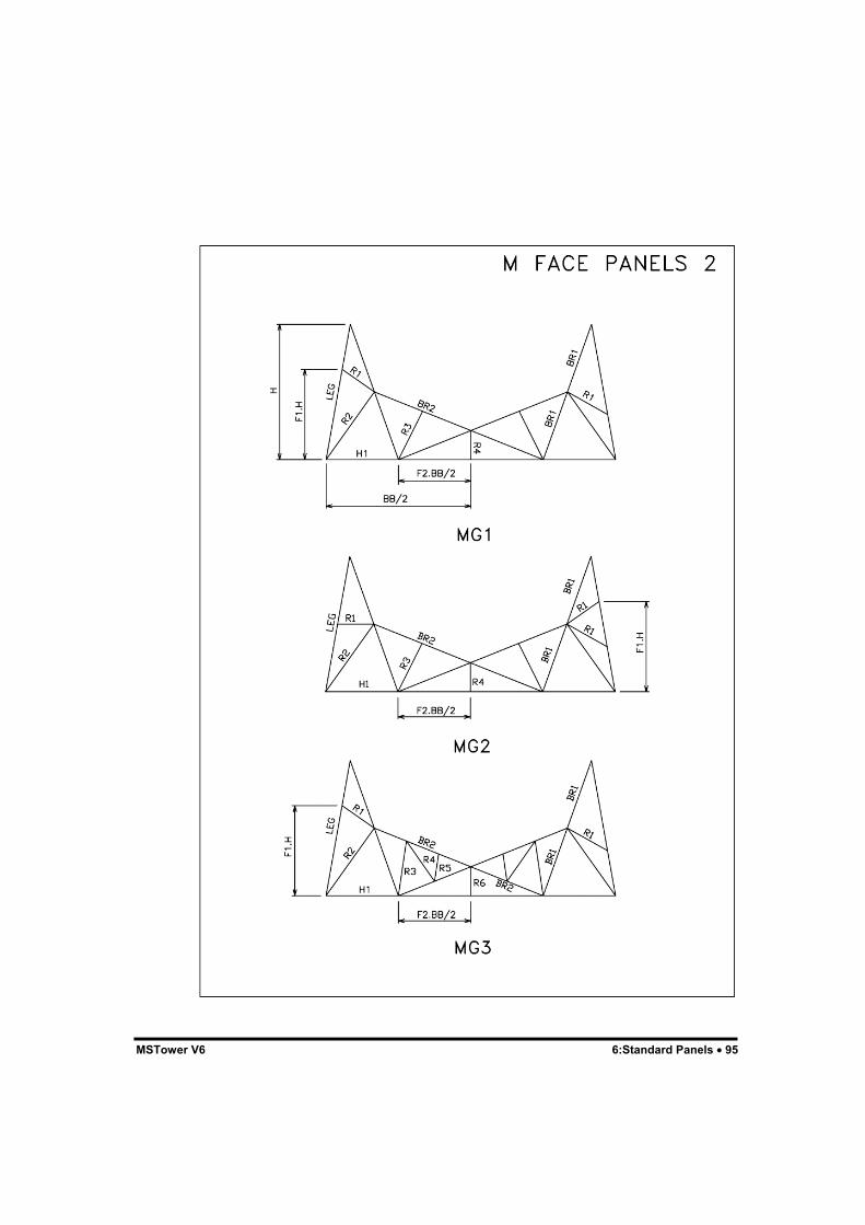
MSTower V6 6:Standard Panels • 95

96 • 6:Standard Panels MSTower V6
W Face Panels

MSTower V6 6:Standard Panels • 97

98 • 6:Standard Panels MSTower V6
XMA Face Panel

MSTower V6 6:Standard Panels • 99
XDMA Face Panel

100 • 6:Standard Panels MSTower V6
DM, DM2 Face Panel

MSTower V6 6:Standard Panels • 101
DMH, DMH2 Face Panel

102 • 6:Standard Panels MSTower V6
DLM, DLM2 Face Panel

MSTower V6 6:Standard Panels • 103
KXM, KXM2 Face Panel

104 • 6:Standard Panels MSTower V6
SH3, SH4

MSTower V6 6:Standard Panels • 105
Plan Bracing

106 • 6:Standard Panels MSTower V6

MSTower V6 6:Standard Panels • 107

108 • 6:Standard Panels MSTower V6
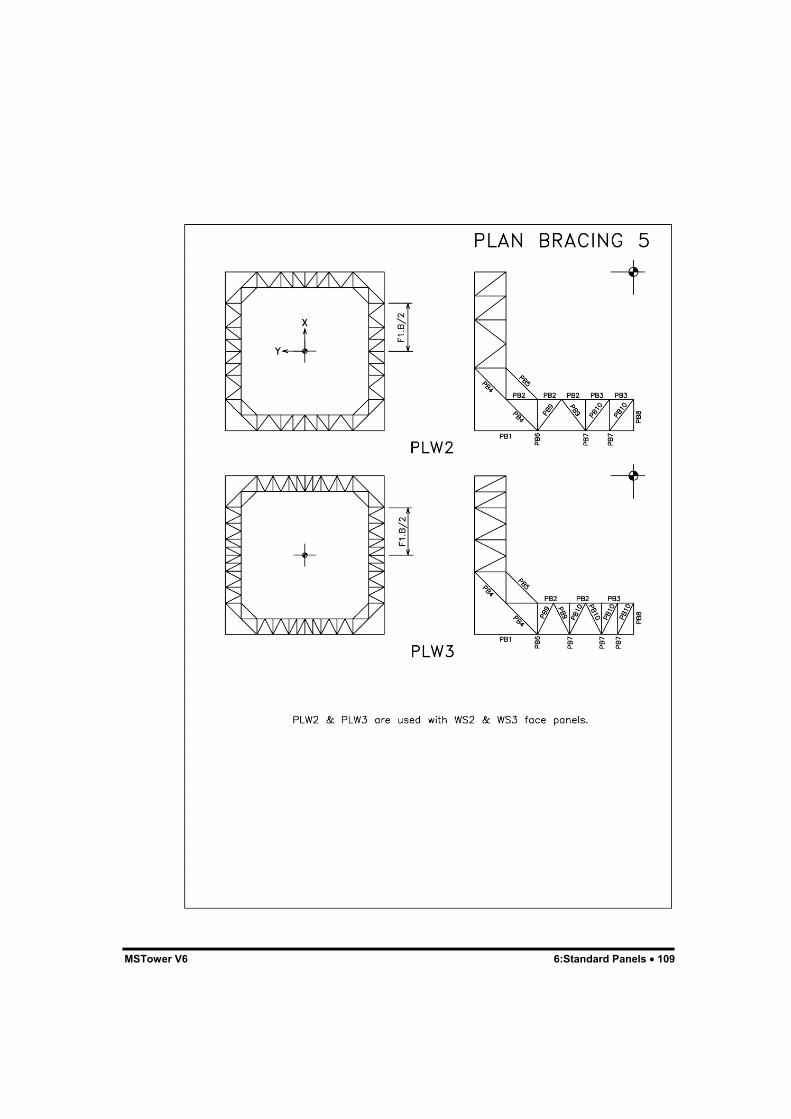
MSTower V6 6:Standard Panels • 109

110 • 6:Standard Panels MSTower V6

MSTower V6 6:Standard Panels • 111

112 • 6:Standard Panels MSTower V6
Hip Bracing

MSTower V6 6:Standard Panels • 113

114 • 6:Standard Panels MSTower V6

MSTower V6 6:Standard Panels • 115
Cross-Arms

116 • 6:Standard Panels MSTower V6

MSTower V6 7:User-Defined Panels • 117
7:User-Defined Panels
GeneralWhile MStower has an extensive set of standard panels, there will betimes when some variant will be required to model a particular panel.MStower allows you to create your own panels – user-defined panels, orUDPs, for just this purpose. Unlike standard panels, which are scaled tothe dimensions specified in the tower data file, UDPs once created are offixed size.Although data for the UDP is contained in a text file which may beedited, the most expeditious way of creating a UDP is to start bybuilding a tower with standard panels that are as close to the finalconfiguration as possible, and then to extract and graphically edit a panelas required. MStower has facilities (see “8:Graphics Input for UDPs” onpage 127) that allow UDPs to be created and manipulated using a CAD-like interface. For most UDPs you will never need to edit the text file.

118 • 7:User-Defined Panels MSTower V6
The UDP FileData for user-defined panels must be included in one or more separateUDP files. The file names are specified in the COMPONENT block of thetower data file. The data may represent a full face, a half face, a quarterof a section of the tower, a pair of adjacent faces, or a complete threedimensional section of the tower, depending on which is mostconvenient for describing the panel. MStower will generate the completepanel. The data for the user-defined panel is:UDP udp HT ht TW tw BW bw {PLANE | HALF | QUART | ADJA | 3DIM} NODE n x y z .. MEMB m ia ib ic mp mm pina pinb class [subclass] ..END
where:UDP Keyword.udp Name of user-defined panel as used in the COMPONENT block
of the tower data file..HT Keyword.ht Height of panel. This should be the height of the panel between
its points of attachment to the panels above and below. It is notnecessarily the maximum overall height of the panel.
TW Keyword.tw Top width of the panel; i.e. the width of the panel at the level at
which it attaches to the panel above. If not given, the width ofthe tower at this level will be interpolated.
BW Keyword.bw Base width of the panel; i.e. the width of the panel at the level
at which it attaches to the panel below. If not given, the widthof the tower at this level will be interpolated.
PLANE Keyword indicating that the data applies to a plane face that isto be used to generate a full face panel. The panel lies in the Y-Z plane with all X coordinates zero.
HALF Keyword indicating that the data applies to half a plane facelying in the YZ plane with all X coordinates zero.
QUART Keyword indicating that the data applies to two adjacent halfpanels disposed about the leg in the positive X and negative Yquadrant.
ADJA Keyword indicating that the data applies to two adjacent faces.This is used for panels where the adjacent faces differ. Thepositive X and positive Y faces should be defined.
3DIM Keyword indicating that the data applies to a full three-dimensional section of the tower.

MSTower V6 7:User-Defined Panels • 119
NODE Keyword.n Node number.x X coordinate of node.y Y coordinate of node.z Z coordinate of node. The points of attachment to the panel
immediately below should have Z coordinates of zero.MEMB Keyword.m Member number.ia Node number of the “A” end of the member.ib Node number of the “B” end of the member.ic Reference or “C” node. Face members, such as legs and braces,
should have a node in the plane of the face as their referencenode. This is of particular importance for legs that havestaggered face bracing and for face braces such as unequalangles that must have a particular orientation.
mp Section property number. The section must be defined in theSECTIONS block of the TD file.
mm Material number, usually 1.pina Pin code for “A” end of member, a six character string of 0s
and 1s. From the left, 1s represent force releases for Fx, Fy, Fz,Mx, My, and Mz, respectively.
pinb Pin code for “B” end of member.class Member class code:
LEG Leg member.BRC Brace member, other than XBR or KBR.XBR X brace, symmetrically braced.KBR K brace, symmetrically braced.HOR Horizontal member.HBR Hip brace.PBR Plan brace. This code applies only to the internal members of plan bracing. Any plan brace member in the face of the tower must be classified as HOR.RED Redundant member.CRM Cross-arm main memberTBR Tension only bracing.WND Wind only. See note below.
subclass Optional numeric code to allow bolt details for UDP member tobe specified. It allows members of a particular class to bedifferentiated if their bolting details differ. For example:
...BRC 1 – uses bolt details for BR1
...BRC 2 – uses bolt details for BR2
The UDP name must be an alphanumeric label that cannot be interpretedas a number (e.g. 10, E10, and D1 are not allowed as UDP names). Thedimensions of the UDP are taken from its coordinates. The height and

120 • 7:User-Defined Panels MSTower V6
panel widths are used to locate the UDP in the tower and to allow anystandard panels that are above or below the UDP to be correctly scaled.Unlike standard panels, user-defined panels cannot be scaled.Wind-only members attract wind load and are included in the analysisbut are not regarded as providing any structural restraint to othermembers. The strength of wind-only members is not checked.
UDPs

MSTower V6 7:User-Defined Panels • 121
UDPs

122 • 7:User-Defined Panels MSTower V6
Making A UDP Using Graphics InputThe simplest way to make a UDP is to generate a tower using standardpanels that are similar to the required panel and then to use graphicalinput to extract the panel and make any necessary modifications.MStower has commands to convert this to a UDP but the componentreferences must be included in the tower data (TD) file using the editor.See “8:Graphics Input for UDPs” on page 127 for details and anexample.The name of the UDP and its type (PLANE, HALF etc.) will berequested. The HT, TW, and BW will be filled in but should be checked,particularly in the case of cross-arms.If the UDP contains leg members, the HT, TW, and BW values will bedetermined by examining the coordinates of those nodes that are on legs.The Z coordinates of all nodes will be adjusted so that the lowest “legnode” has a Z coordinate of zero. If the UDP does not contain legmembers, the HT value will be set to zero and no adjustment will bemade to the Z coordinates.
Note: Member classes may be specified directly. It is not necessary toinput dummy material numbers as required in previous versions.
UDPs for PolesUDP members may be connected to the nodes on the shaft of the pole orto the nodes at the ends of the radial members. Pole leg and radialmembers must not be included in the UDP.A good starting point for a pole with UDPs is to generate a pole withcross-arms at the required heights and then to graphically edit the UDPsthat form the cross-arms.
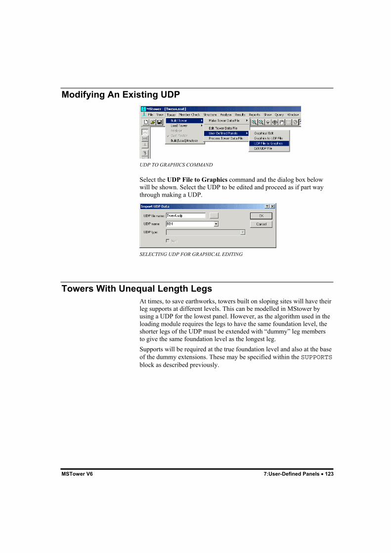
MSTower V6 7:User-Defined Panels • 123
Modifying An Existing UDP
UDP TO GRAPHICS COMMAND
Select the UDP File to Graphics command and the dialog box belowwill be shown. Select the UDP to be edited and proceed as if part waythrough making a UDP.
SELECTING UDP FOR GRAPHICAL EDITING
Towers With Unequal Length LegsAt times, to save earthworks, towers built on sloping sites will have theirleg supports at different levels. This can be modelled in MStower byusing a UDP for the lowest panel. However, as the algorithm used in theloading module requires the legs to have the same foundation level, theshorter legs of the UDP must be extended with “dummy” leg membersto give the same foundation level as the longest leg.Supports will be required at the true foundation level and also at the baseof the dummy extensions. These may be specified within the SUPPORTSblock as described previously.

124 • 7:User-Defined Panels MSTower V6
Creating a UDP from a Microstran Job
Note: Any Microstran job from which you want to create a UDP mustbe compatible with the basic assumptions in MStower: the Z axis isvertical and forms the central axis of the tower and there is a face normalto the positive X axis. It is not difficult to adjust a job in Microstran thatdoes not meet these requirements.
Step 1* Have MStower job (TOWR for example) and Microstran job (MICROfor example) in the same data folder. Do not use the same name for bothjobs.Step 2* Open the Microstran job in Microstran.* Export an archive file using the name of the MStower job (TOWR for example).* Close the Microstran job.Step 3* Edit the archive file in Microstran and change the name of theMicrostran library to that of the MStower library, e.g. change “Ukw.lib”to “Uk.lib”.Step 4* Open the MStower job in MStower.Step 5* Select the command: Tower > Build Tower > User Defined Panels > Graphical Edit* Select the command: Files > Import > Archive File to import the Towr.arc file.* Delete members not in the UDP.* Define member classes.* Select the command: Tower > Build Tower > User Defined Panels > Graphics to UDP File* Check that UDP file name is Towr.udp.* Input the UDP name and UDP type.

MSTower V6 7:User-Defined Panels • 125
Step 6* Edit tower data file, add UDP to COMPONENT block in usual way, and rebuild tower.* Fix any problems that are apparent.* Save.Step 7* Repeat steps 5 and 6 to extract further UDPs from the Microstranarchive.
While step 5 could be repeated without step 6, it is usually better tocheck each UDP by building the tower as in step 6.
UDP File NamesIt is simplest to have all UDPs for a job in a single file that is namedafter the job, i.e. Job.udp, where “Job” is the name of the job. TheCOMPONENT block in the TD file may then have the form:
COMPONENT
UDP1
UDP2
..
END
Here, the name of the file containing the UDPs is omitted and MStowerassumes them to be in a file named Job.udp, where “Job” is the name ofthe job. When the job is saved the UDP file will be saved automaticallywith it. Also, if the job is renamed in a Save As operation the UDP filewill be renamed.It is not mandatory for the UDP file to be named after the job. Forexample, if you have a number of towers all with a particular panel thatis a UDP you may place the UDP in a file not named after the job and itmay then be referenced by any number of jobs. The main advantage ofthis is that the UDP needs to be created only once. Any changes to theUDP will apply to all jobs that use the panel when those jobs are rebuilt.If the changes are not required for all towers referencing the UDP youmust make the changes in a copy of the UDP file and change thereferences in the COMPONENT block of each tower that is to use themodified UDP.
Note: Only UDPs in a file named after the job are automatically savedwhen the job is saved.


MSTower V6 8:Graphics Input for UDPs • 127
8:Graphics Input for UDPs
GeneralGraphics Input is the most efficient input method of inputting a user-defined panel. It involves “drawing” a structure on the screen using themouse or keyboard, and it includes many simple graphical operations,such as copying, moving, rotating, sub-dividing, and erasing. Morepowerful graphical operations include intersection, extrusion, andtransforming coordinates. In effect, MStower’s graphical input capabilityis an intelligent CAD system customized for the task of enteringstructure data.
GRAPHICS INPUT
You may find that the few hours required to become proficient atgraphical input will be well rewarded by much increased productivity increating and editing UDPs.

128 • 8:Graphics Input for UDPs MSTower V6
Note: Many MStower commands involve the use of the context menu.This is a menu, which is specific to the current operation, that appearswhen you right-click (press the right mouse button). For example, whenyou are drawing a series of members, after clicking on the DrawMembers button (the one with the pencil), you click the location of eachnode, and to finish the operation, you right-click and select Break Lineor End Line on the context menu. Also, after you have selected nodes ormembers for any operation, you right-click and choose OK or Cancel onthe context menu.
Basic DrawingGraphics Input is started by selecting Tower > Build Tower > User-Defined Panels > Graphics Edit. You will also be in Graphics Inputmode when you import an existing UDP by selecting Tower > BuildTower > User-Defined Panels > UDP To Graphics.
To start drawing a UDP, click on the toolbar button. This is the sameas selecting the Structure > Draw Members command from the mainmenu. Notice the tooltip “Draw Members” that appears when the mousecursor crosses this button.As you initiate the Draw command several things happen:1. The toolbar button displays in the depressed state, indicating that
MStower is in DRAW mode.2. “DRAW” is displayed in the status bar at the bottom of the
MStower window.3. The prompt area of the status bar (on the left) displays the
instruction “Click on first point or enter coordinates”.4. The cursor becomes a cross.You may now click anywhere in the main window or enter coordinatesfrom the keyboard to locate the “A” node of the first member. Noticethat once the first point is specified the prompt changes to “Click on endpoint or enter coordinates; press SPACE BAR to break line”. Selectanother point and you will have drawn the first member. This point is the“B” node of the first member and the “A” node of the next member. Youmay continue selecting points to define new members.
Keyboard Entry of CoordinatesThere are many situations where the most convenient way to enter a newnode is to type the coordinates. As soon as you start to type, a dialog boxappears to accept your input.

MSTower V6 8:Graphics Input for UDPs • 129
DIALOG BOX FOR ENTERING COORDINATES
Coordinate SystemsYou may input coordinates in rectangular, cylindrical, or sphericalcoordinate systems, using standard syntax or AutoCAD syntax. Theformat of the coordinate string is described below for each syntax.STANDARD SYNTAX• Rectangular coordinates
“X Y Z”, where “X”, “Y”, and “Z” are respectively, the X, Y, and Zcoordinates of the point.
• Cylindrical coordinates“C radius theta h”, where “radius”, “theta”, and “h” are respectively,the radius, horizontal angle, and height of the point.
• Spherical coordinates“S radius theta phi”, where “radius”, “theta”, and “phi” arerespectively, the radius, horizontal angle, and vertical angle of thepoint.
Trailing zero coordinates do not have to be entered. For example, thepoint (3,0,0) may be entered as “3”. Coordinates must be separated by aspace or a comma. Coordinates relative to the last point are preceded by“R” or “r”. No separator is required after the “R” or “r”.AUTOCAD SYNTAX• Rectangular coordinates
“X Y Z”, where “X”, “Y”, and “Z” are respectively, the X, Y, and Zcoordinates of the point.
• Cylindrical coordinates“radius < theta h”, where “radius”, “theta”, and “h” are respectively,the radius, horizontal angle, and height of the point. The last twovalues must be separated by a space or a comma.
• Spherical coordinates“radius < theta < phi”, where “radius”, “theta”, and “phi” arerespectively, the radius, horizontal angle, and vertical angle of thepoint.
Coordinates relative to the last point are preceded by “@”. No separatoris required after the “@”.Breaking the LinePress the space bar or right-click and choose Break Line on the contextmenu. Notice that the cursor, the status bar, and the button show thatMStower is still in Draw mode. You may now click a new node that isnot connected to the last by a member.

130 • 8:Graphics Input for UDPs MSTower V6
Ending the LineRight-click and choose End Line on the context menu. Notice the cursorchange to the standard arrow. This indicates that the command isfinished. The status bar and the button also show that MStower is nolonger in Draw mode.
The Drawing Snap Mode
Key concept.
Initially, the status bar displays NONE for the snap mode. This meansthat the coordinates of any node defined by clicking the mouse will beindeterminate to some extent, because the degree of accuracy with whichyou can position the mouse is limited. Practically, therefore, the snapmode NONE is rarely used. The first few nodes are usually specified bygrid points or entry of coordinates. Thereafter, the Mid/End snap mode isusually used.Grid Snap Mode (GRID)In Grid mode the status bar displays GRID. Grid spacing is initially 1unit in each global axis direction but you may change it with theStructure > Drawing Settings > Grid Spacing command. When thegrid is displayed the cursor snaps to the nearest grid point. Thus, withthe mouse, you can only draw members from one grid point to another.Enter coordinates to specify a point that is not on the grid.Mid/End Snap Mode (MEND)When drawing in this mode the cursor snaps to a nearby member end ormid-point. Most graphical input is done in this snap mode. When startinga new structure you cannot enter Mid/End snap mode because there areno members to snap to.Intersection Snap Mode (INTR)When drawing in this mode the cursor snaps to a nearby intersection oftwo or more members. A new node is automatically introduced at theintersection point if there is not already a node there. When starting anew structure you cannot enter Intersection snap mode until there are atleast two members.Perpendicular Snap Mode (PERP)In this mode the cursor snaps to the point on a target member that makesthe new member perpendicular to the target member. When starting anew structure you cannot enter Perpendicular snap mode until there is atleast one member.Orthogonal Snap Mode (ORTH)In this mode you can only draw members in a global axis direction.Nearest Snap Mode (NEAR)In this snap mode the cursor snaps to the point on a target member that isnearest to the cursor location.

MSTower V6 8:Graphics Input for UDPs • 131
Changing the Snap Mode “On the Fly”A very convenient feature is the ability to change the snap mode during adraw operation. For example, you may click the start point of a newmember at the end of another while in Mid/End snap mode and thenchange to Grid snap mode to select the end point. Right-click to displaythe context menu with its selection of snap modes (see diagram at thebeginning of this chapter).
The Drawing PlaneThe drawing plane is a plane on which nodes are located when you drawin either the Grid or NONE snap modes. For example, when drawing inGrid snap mode with default settings, the drawing plane is X-Y at anoffset of zero along the Z axis. This means that all new nodes drawn inGrid or null snap mode have a Z coordinate of zero. Changing the viewwith any of the Front View, Back View, Right View, Left View, orTop View commands automatically changes the drawing plane so that itis parallel to the view plane.Use the Structure > Drawing Settings > Drawing Plane command tochange the drawing plane as required. If you change the view or thedrawing plane so that it (the drawing plane) is at right angles to the viewplane (the plane of the screen) you may see the warning message shownbelow and you may not be able to click a new point.
WARNING THAT DRAWING PLANEIS PERPENDICULAR TO SCREEN
Automatic Removal of Duplicate Nodes and MembersAt various stages during graphical input operations, MStower removesany duplicate nodes or members that are detected. The first node ormember to be drawn will remain and any that are superimposed will beremoved automatically. This behaviour has two significantconsequences:• Overlapping nodes and members in copy operations are ignored.• In drawing members, you may draw over an existing member
instead of breaking the line.

132 • 8:Graphics Input for UDPs MSTower V6
Cursors
Key concept.
MStower displays various cursors at different times, depending uponwhat is happening. These cursors are shown below:
Cursor DescriptionCommand mode. MStower is waiting for you to select a commandfrom the menu, click a toolbar button, or select a node or member (thecursor changes as soon as you select a node or member).Drawing mode. MStower is waiting for you to click an end of amember. Look at the right of the status line to determine which snapmode is in effect. You may use the Structure > Drawing Settingscommand or the context menu to change the snap mode withoutleaving the current drawing command.Member selection mode. MStower is waiting for you to select one ormore members by clicking on them or enclosing them in a selectionbox. If you drag a selection box from left to right, cut members areexcluded. Dragging from right to left includes cut members.
Node selection mode. MStower is waiting for you to select one ormore nodes by clicking on them or enclosing them in a selection box.
This cursor appears when you are selecting a zoom window orpanning. When zooming, drag from one corner to the diagonallyopposite corner of the rectangle you want to zoom to. When panning,click on any part of the structure and drag to the new location for thatpart.
Generally, when you have finished a command, MStower allows you torepeat the command until you cancel the command by right-clicking. Forexample, when you select the Structure > Erase Members command,the cursor changes, you then select members you want to erase andconfirm the selection by right-clicking and choosing OK on the contextmenu. The member selection cursor is still displayed, allowing you tochoose more members to erase. To terminate the command, right-click,and the standard arrow cursor will reappear.Many commands are interruptible. This permits you to adjust the viewduring a command. When drawing members in a large model, forexample, having clicked the “A” node of a member, you may need tozoom in to another region of the structure before clicking the “B” node.

MSTower V6 8:Graphics Input for UDPs • 133
Shortcut KeysMStower permits the use of shortcut keys to some commands. Shortcutkeys are also known as accelerator keys. Below is a complete list ofMStower’s shortcut keys:
Shortcut CommandCtrl+C CopyCtrl+X CutCtrl+V PasteCtrl+Z UndoCtrl+Y RedoF5 RedrawCtrl+A Select AllDelete Erase MembersHome Zoom Extents/Limits
Viewpoint LeftViewpoint RightViewpoint UpViewpoint Down
Space Break Line
The effect of pressing a shortcut key depends on the context. Forexample, pressing Delete usually deletes selected members, but in adialog box it may delete text.
Selecting Nodes and Members
Key concept.
In MStower, when you choose a command, you usually select the nodesor members that are the object of the command. This may be done inseveral ways:• Clicking each node or member in turn. Clicking again on a node or
member deselects it.• Dragging a selection box that encloses the nodes or members to be
selected. “Dragging a selection box” means clicking (with the leftmouse button) a point away from the nodes or members to beselected, then dragging the mouse until the selection box enclosesthe necessary nodes or members, and finally, releasing the leftmouse button. Note that when the selection box is dragged fromright to left, a “crossing window” appears, which selects not onlymembers enclosed by the box but also members cut by the sides ofthe box.

134 • 8:Graphics Input for UDPs MSTower V6
• Clicking a selection box. This is similar to dragging a selection boxbut instead of clicking, dragging, and releasing the mouse button,you click two points to define diagonally opposite corners of theselection box.
• All members may be selected by Ctrl+A (see “Shortcut Keys“,above).
In all cases, you confirm the selection by right-clicking and choosingOK on the context menu.
Right-Clicking on Nodes and Members
Key concept.
MStower fully implements the Windows protocol for right-clicking onobjects to obtain a pop-up of related commands. This provides analternative method of operation:• Select node(s) or member(s).• Right-click to choose required operation on context menu.Right-clicking on a node will cause this context menu to appear:
NODE CONTEXT MENU
Double-clicking on a node is the same as selecting Properties on thispop-up menu.The following pop-up menu appears when you right-click on a member:
MEMBER CONTEXT MENU
Double-clicking on a member is the same as selecting Properties on thismenu.

MSTower V6 8:Graphics Input for UDPs • 135
The Node Properties Dialog BoxThe dialog box shown below appears when you double-click a node orselect Properties after right-clicking a node.
NODE PROPERTIES DIALOG BOX
The OK button in this dialog box is disabled. You may use the dialogbox to check properties but you will not be able to change them.
The Member Properties Dialog BoxThe dialog box shown below appears when you double-click a memberor select Properties after right-clicking a member.
MEMBER PROPERTIES DIALOG BOX
The OK button in this dialog box is disabled. You may use the dialogbox to check properties but you will not be able to change them.

136 • 8:Graphics Input for UDPs MSTower V6
Properties Dialog Boxes with Multiple Selection
Key concept.
You may select several nodes or members, then right-click and chooseProperties on the context menu. The dialog box will display commonproperties of the selected group of nodes or members. Blank edit boxesindicate that the corresponding value is not the same for all of themultiple selection.
Extrusion
Key concept.
There is a check box for “Extrude nodes” in each of the Linear Copy,Polar Copy, and Reflect dialog boxes. When you perform a copyoperation you may “extrude” each copied node into a series of members– in other words, there will be a string of new members lying on the pathtraced out by each node involved in the copy operation. The member xaxis is aligned with the direction of extrusion.
Interrupting CommandsThe diagram below shows the View toolbar, normally docked at the topof the MStower window.
VIEW TOOLBAR
Most commands may be interrupted in order to change the view byclicking on one of these buttons. This is helpful in many situations, forexample, when drawing a member, and the view required for displayingthe “B” node is different from that in which the “A” node is visible. Youmay interrupt graphical commands to rotate the view, zoom in to acongested area of the model, or pan the view, as required.You may also interrupt commands by clicking buttons on the Displaytoolbar, shown below.
DRAW TOOLBAR

MSTower V6 8:Graphics Input for UDPs • 137
The Stretch CommandThe Structure > Move > Stretch command applies a lineartransformation to the coordinates of selected nodes. The prompts in thestatus bar guide you through the necessary steps in this command:• Select nodes• Select node as fixed point• Select node as start point of stretch vector• Select node as end point of stretch vectorAn example is illustrated below, where the top chord nodes of a truss are“stretched” to introduce a uniform slope from one end to the other.
Firstly, a member is added to represent the stretch vector. All the nodesto be transformed are highlighted. Node 2 is selected as the fixed node.
Nodes 12 and 13 are selected to define the stretch vector. The diagrambelow shows the truss on completion of the command.
If you inadvertently click on the wrong node when selecting the fixednode or the start of the stretch vector, you can abort the command byselecting the start of the stretch vector as the end point also.The Stretch command could be used to input tower cross-arms as aparallel chord truss, which is later tapered, as in the example above.

138 • 8:Graphics Input for UDPs MSTower V6
The Limit Command
VIEW > LIMIT > WINDOW
The commands on the View > Limit menu allow you to restrict activityto a selected part of the structure. The rest of the structure may be greyedout or hidden from view. This has the advantage that the view you areworking on is uncluttered by irrelevant detail and the rest of the structureis inaccessible while Limit is in effect.
The Limit > Window command, , was used to select one segment ofthe tower in the diagram below. To hide the rest of the structure right-click and uncheck Show Outside Limits.
LIMIT > WINDOW

MSTower V6 8:Graphics Input for UDPs • 139
When the Limit command is in effect, clicking this button, ,(equivalent to the View > Zoom > Extents/Limits command) will zoomthe view so that the full structure and the limited part alternately fill thescreen.
The Limit > Boundary command, , may be used to select a part ofthe tower using a selection polygon.
Clicking the Full View button, , reverses the effect of the Limitcommand.
Removing an Intermediate NodeYou may occasionally want to remove an intermediate node in amember. If you had accidentally sub-divided a member (while drawingin Mid/End snap mode, for example), you may want to restore it to asingle member. This can easily be done as follows:1. Select Mid/End snap mode if this mode is not already selected.2. Right-click on the intermediate node to be removed.3. Select Move Node on the context menu – the node should now be
attached so you can drag it.4. Drag the node to one end of the member containing it and click.This procedure does not give rise to a duplicate node or a zero-lengthmember.

140 • 8:Graphics Input for UDPs MSTower V6
UDP Graphical ExampleThis example illustrates the graphical creation and modification of asimple UDP.
Step 1 – Create Data File for a Small Tower* Select the commandTower > Build Tower > Make Tower Data File > Tower/Mast Dataand complete the dialog boxes to create a square tower with 4 panels,two X panels of height 2m and 2.5m on top of two K panels, each ofheight 4m.
GEOMETRY PARAMETERS DIALOG BOX
* Check the box to provide a skeleton block for UDPs and removechecks from all other options. The tower width must be defined at bendpoints only. In this case, input a top width of 2m for the first panel andzero for the remaining panels. MStower interpolates all intermediatewidths.
PANEL DATA DIALOG BOX
This is the data file generated:

MSTower V6 8:Graphics Input for UDPs • 141
TITL1 Example for UDP inputTITL2UNITS 1 $ 1=metric, 4=US
COMPONENT $ TODO - udp list goes hereEND
PROFILEFACES 4WBASE 4.0000RLBAS 0.0000
$ TODO:$ Remove '$' and replace '?' with appropriate$ section numbers in following PANEL blocks.
PANEL 1 HT 2.000 TW 2.000 FACE X $ LEG ? BR1 ? H1 ?
PANEL 2 HT 2.500 FACE X $ LEG ? BR1 ? H1 ?
PANEL 3 HT 4.000 FACE K $ LEG ? BR1 ? H1 ?
PANEL 4 HT 4.000 FACE K $ LEG ? BR1 ? H1 ?
END
END

142 • 8:Graphics Input for UDPs MSTower V6
Step 2 – Build Tower* Select the commandTower > Build Tower > Process Tower Data Fileto build the tower and check that the basic geometry is correct. Becausethe sections have not yet been defined there will be an error but thetower should build and display correctly, as shown below.
BUILT TOWER
Note that the Draw and Attributes toolbars on the right of the screen aredisabled at this stage.
Step 3 – Isolate UDP Members* Select the commandTower > Build Tower > User Defined Panels > Graphical EditMStower is now in graphical editing mode and the Draw and Attributestoolbars are enabled.We wish to convert panel 3 into a UDP and we start by selecting asuitable view and deleting members of other panels:
* Click the button to obtain a front view of the tower.
* Click the button.* Click and drag to create in turn two selection boxes as shown below.Note that the top box is a “crossing window”, dragged from right to leftto select all members either inside or crossed by the box, while thebottom box is dragged from left to right and only selects memberswholly within it.

MSTower V6 8:Graphics Input for UDPs • 143
ERASING MEMBERS OF OTHER PANELS
* Click the right mouse button to confirm the selection. Only themembers of panel 3 should now be displayed.
Note: If you are unsure about methods of selection and graphical inputyou should review material at the beginning of this chapter.
Step 4 – Add Members to UDP* Click the button to obtain a plan view of the panel.* Add members to the panel so that it looks like a K1 panel. This is doneby drawing the members in the top right corner of the view and thencopying the new members to the other corners.
* Click the and buttons to display node and member numbersfor easy identification.
* Click the button to start drawing members.* Click on node 105 (at top of the leg).* Click about half way along member 224 (brace). After each click a“rubber band” line joins the cursor to the point clicked on.* Click about half way along member 221 (leg).* Click about half way along member 205 (brace).* Click on node 105.* Right-click and select End Line to terminate the drawing sequence.

144 • 8:Graphics Input for UDPs MSTower V6
The panel should now appear as shown below (for clarity, node andmember numbers are not shown). Notice that when the cursor hoversover a node or member a “data tip” will be displayed. On the originalmembers the data tip has an indication of member class (LEG, HOR,etc.) but on the new members this is absent.
REDUNDANT MEMBERS ADDED TO UDP
Step 5 – Define Attributes of New MembersIn this step we define the section number, reference nodes, member endreleases (if any), and member classes of the new members.* Select the commandStructure > Attributes > Section Numberand click on the new members; right-click to confirm the selection. Nowspecify the new section number, say 5, in the dialog box that appears.
Note: You may double-click on any member to see all its properties.
* Select the commandStructure > Attributes > Member Classand click on the new members; right-click to confirm the selection. Nowchoose class Redundant, sub-class R1.
Step 6 – Copy New Members to Other Faces* Select the commandStructure > Copy > Polarand click on the new members; right-click to confirm the selection. Thenode selection cursor, , is now visible and the prompt reads “Click on

MSTower V6 8:Graphics Input for UDPs • 145
center of rotation or enter coordinates”. There is no node on the verticalaxis of the tower, so the center of rotation must be defined by typingcoordinates.* Type 0 and press Enter. A dialog box appears when you type the firstnumber and displays the coordinates of the point to be used as the centerof rotation. The zero entered is interpreted as (0,0,0) – i.e. trailing zeroesare ignored.* In the Polar Copy dialog box enter Z as the axis of rotation, 90 as theangle increment, and 3 as the number of copies. Press Enter or click OK.Copies of the new members should now be displayed at all corners.
Step 7 – Set Reference Nodes for New Members* Select the commandStructure > Attributes > Reference NodeThe y axis of each new member will lie in the face plane, so a referencenode is chosen in the face.* Select the four new members on the +X face, right-click to confirm theselection, and then click on node 203.* Select the four new members on the +Y face, right-click to confirm theselection, and then click on node 223.* Repeat the last operation for the members in the –X and –Y faces usingappropriate reference nodes.
Note: A reference node must not lie on the longitudinal axis of themember or the extension of the longitudinal axis.
Step 8 – Check UDPThe UDP has now been fully defined but before proceeding further it isadvisable to make certain checks. For example, to check that all newmembers have been assigned a class, use the commandShow > Member Classes > Unclassified MembersThis command highlights any unclassified members.
Step 9 – Convert Graphics to UDP File* Select the commandTower > Build Tower > User Defined Panels > Graphics to UDP File* In the displayed dialog box enter P3 for the UDP name.* Select 3-DIM as the UDP type.* To make the UDP known as a component of the tower select thecommandTower > Build Tower > Edit Tower Data

146 • 8:Graphics Input for UDPs MSTower V6
* The UDP file is displayed in the text editor, MsEdit, so you can makethe necessary changes:
COMPONENT P3END
PANEL 3 HT 4.000 $ FACE K $ LEG ? BR1 ? H1 ? R1 ? FACE @P3
Here, the FACE K line has been commented out with the $ character butretained in the file to indicate the panel type used as the basis for theUDP.* Save the edited TD file and close MsEdit.* Rebuild the tower and inspect to ensure that the UDP is as required.* If the UDP must be modified select the commandTower > Build Tower > User Defined Panels > UDP File to Graphicsand select the UDP to be modified (P3 in this case).* After making any necessary modification select the commandTower > Build Tower > User Defined Panels > Graphics to UDP FileIf the UDP file already exists a message box is displayed…
* Press Enter or click OK.* Rebuild the tower.

MSTower V6 9:Tower Loading • 147
9:Tower Loading
GeneralThis chapter describes the operation of the MStower loading module incomputing loads on the tower and ancillaries in accordance with therequirements of:
• BS 8100 Part 1 2005• BS 8100 Part 4 1995• BS 8100 Part 4 Amendment 1 2001• AS 3995-1994• AS 1170.2-2002• Malaysian Electricity Supply Regulations 1990• EIA/TIA-222-F-1991• TIA-222-G-2005• Institution of Lighting Engineers Technical Report No. 7 –
High Masts for Lighting and CCTV – 2000 Edition• IS 875 (Part 3):1987• ASCE 7-95• BNBC 93 – Bangladesh National Building Code
Loading types include dead load, ice load (with and without wind), nodeloads, wind loading on the structure, its ancillaries, feeders, andattachments, and temperature loads.Tower loading represented as node loads are computed for wind actingat any angle to the tower, with and without icing of members, as well asgravity loads due to self weight and icing. Additional node forces maybe specified for any primary load case. Combination load cases may alsobe defined.Code partial safety factors may be specified directly or as factors incombination load cases.

148 • 9:Tower Loading MSTower V6
Tower FacesThe faces of the tower are numbered 1, 2, 3 (and 4 for rectangulartowers) in an anti-clockwise direction with face 1 normal to the positiveX axis. The locations of face ancillaries are specified by reference to theface numbers.Towers With Cross-ArmsThe wind resistance of a tower is generally computed as a function of thesolidity of the faces of the tower. Members internal to the body of thetower are ignored in the determination of solidity. Members external tothe body of the tower, such as cross-arms may be taken into account byadding face ancillaries to appropriate panels or by specifying anEXTERN factor for wind load cases.The weight of the all members, including cross-arms and any encrustingice is taken into account in DL and ICE load cases respectively.
The Tower Loading (TWR) FileData describing the tower loading is entered into a free-format text filecalled Job.twr, where “Job” is the job name. A tower loading file may begenerated by selecting Tower > Load Tower > Make Tower LoadingFile. A series of dialog boxes will be displayed for you to select theloading code and various parameters. The resulting TWR file willrequire some editing to customize it to the particular tower you aremodelling.The data is organized into logical blocks:1. PARAMETERS block2. TERRAIN block3. VELOCITY block (optional)4. Named node block (optional)5. Guy list block (optional)6. External block (optional)7. Loads block8. Panel block (optional)9. Ancillaries blockEach block commences with a keyword identifying the block andterminates with the keyword END. The keyword EOF is used toterminate the file. Each data block is described in this chapter.
Parameters BlockPARAMETERS ANGN an [CODE code]

MSTower V6 9:Tower Loading • 149
[ICE RO ro RW rw] [ALTOP alt] [PSF-V gamma-v] [PSF-M gamma-m] [PSF-M2 gamma-m2] VB vb vtype VICE vi CLASS-G class TOPCAT-G topcat [OVERLAP n] [GRAV grav] [RHO rho] [RPSERV rpserv] [SDAMP sdamp] [ADAMP adamp] [TDAMP tdamp] [FREQ freq] [DMULT dmult] [CDMIN cdmin]END
where:ANGN Keyword.an The angle, in degrees, measured anti-clockwise from the X axis
to geographic north.CODE Keyword.code Character string indicating the code rules to be followed in
computing the wind and other loading:BS8100 Use the rules of BS 8100 Part 1 with Amendment 1 – May 2005.BS8100A1 Use the rules of BS 8100 Part 4 with Amendment 1 – April 2003.BS6399 Use the rules of BS 6399.MER Use the rules of the Malaysian Electricity Supply Regulations 1990 – See note below.AS3995 Use the rules of AS 3995.AS1170 Use the rules of AS 1170.EIA222 Use the rules of EIA/TIA-222-F.TIA222G Use the rules of TIA-222-G.ILETR7 Use the rules of the Institution of Lighting Engineers Technical Report No. 7.

150 • 9:Tower Loading MSTower V6
ASCE795Use the rules of ASCE 7-95. These wind rules are the same asthose in Philippines NSCP C101-01.IS875Use the rules of IS 875 Part 3 1987.BNBCUse the rules of the Bangladesh National Building Code.
If omitted, the rules of BS 8100 Part 1 will be used. Unlessspecified otherwise all code references are to BS 8100.
ICE Keyword.RO Keyword.ro Radial ice thickness, mm or inches, in the absence of wind
(BS 8100 Fig. 3.9).RW Keyword.rw Radial ice thickness, mm or inches, in presence of wind
(BS 8100 Fig. 3.9).ALTOP Keyword.alt Altitude of tower top, in m or ft. Used to determine basic ice
thickness (BS 8100 Cl. 3.5.2).PSF-V Keyword.gamma-v Partial safety factor on wind speed and ice thickness, BS 8100
only (BS 8100 Fig 2.1).PSF-M Keyword.gamma-m Partial safety factor on design strength (BS 8100 Fig. 2.1). For
BS 8100 and ILE TR7.PSF-M2 Keyword.gamma-m2 Partial safety factor for bolt capacity, BS 8100 only
(BS 8100-3:1999 Cl. 8.1).VB Keyword.vb Basic wind velocity in m/sec or miles/hour (BS 8100 Fig. 3.1).vtype Character string whose value depends on loading code as
shown below:BS 8100, ILETR7 MEAN = Mean hourly wind speed.
AS 1170.2 / AS 3995 GUST = Gust wind speed.
EIA-222 Blank = Fastest mile wind speed.MER GUST = No additional gust factor applied by program.Refer to individual codes for a full definition of the wind speedto be used.
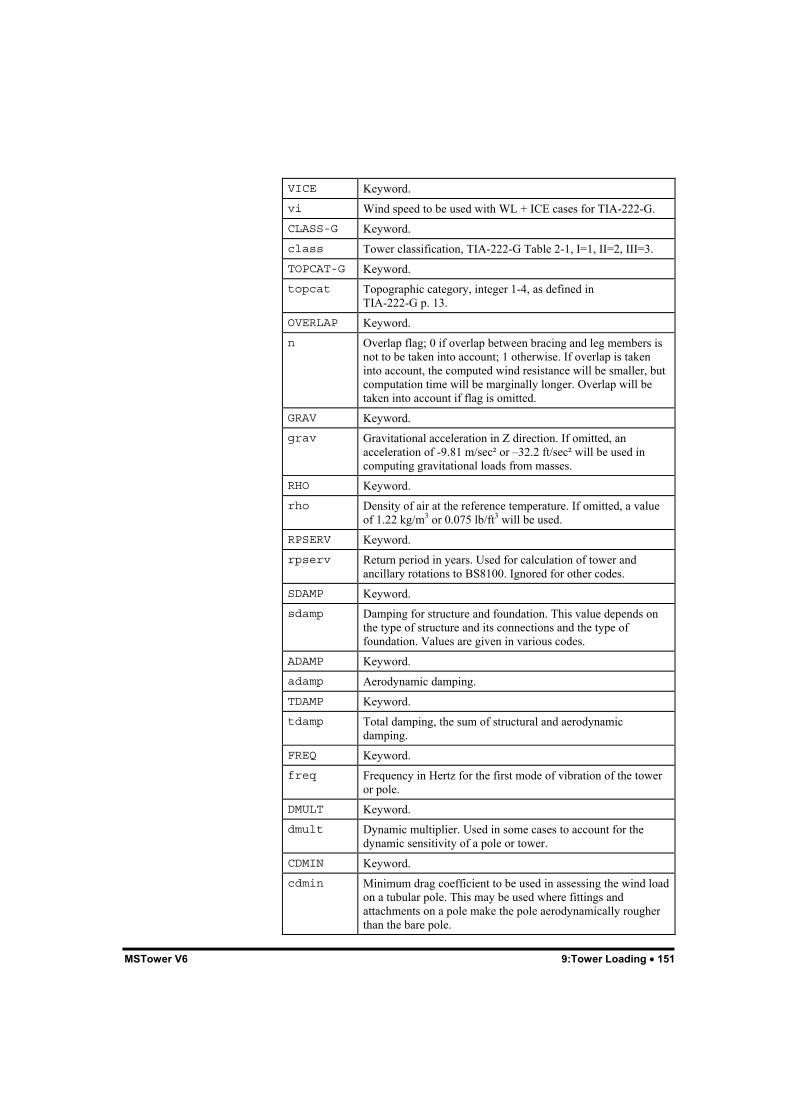
MSTower V6 9:Tower Loading • 151
VICE Keyword.vi Wind speed to be used with WL + ICE cases for TIA-222-G.CLASS-G Keyword.class Tower classification, TIA-222-G Table 2-1, I=1, II=2, III=3.TOPCAT-G Keyword.topcat Topographic category, integer 1-4, as defined in
TIA-222-G p. 13.OVERLAP Keyword.n Overlap flag; 0 if overlap between bracing and leg members is
not to be taken into account; 1 otherwise. If overlap is takeninto account, the computed wind resistance will be smaller, butcomputation time will be marginally longer. Overlap will betaken into account if flag is omitted.
GRAV Keyword.grav Gravitational acceleration in Z direction. If omitted, an
acceleration of -9.81 m/sec² or –32.2 ft/sec² will be used incomputing gravitational loads from masses.
RHO Keyword.rho Density of air at the reference temperature. If omitted, a value
of 1.22 kg/m3 or 0.075 lb/ft3 will be used.RPSERV Keyword.rpserv Return period in years. Used for calculation of tower and
ancillary rotations to BS8100. Ignored for other codes.SDAMP Keyword.sdamp Damping for structure and foundation. This value depends on
the type of structure and its connections and the type offoundation. Values are given in various codes.
ADAMP Keyword.adamp Aerodynamic damping.TDAMP Keyword.tdamp Total damping, the sum of structural and aerodynamic
damping.FREQ Keyword.freq Frequency in Hertz for the first mode of vibration of the tower
or pole.DMULT Keyword.dmult Dynamic multiplier. Used in some cases to account for the
dynamic sensitivity of a pole or tower.CDMIN Keyword.cdmin Minimum drag coefficient to be used in assessing the wind load
on a tubular pole. This may be used where fittings andattachments on a pole make the pole aerodynamically rougherthan the bare pole.

152 • 9:Tower Loading MSTower V6
Note: If code is specified as MER the following default values will beused unless otherwise specified:gamma-v = 1.0gamma-m = 1.0rho = 1.2 kg/m3
vb = 26.82 m/s
DampingBritish codes BS 8100, BS 6399, and ILE TR7 use the logarithmicdecrement of damping, δ. Other codes use the ratio of the actualdamping to the critical damping, ζ, where
δ = 2π ζ / √(1 – ζ2)
Basic VelocityThe definition of the basic velocity vb depends on the code being used.
AS 1170.2 VR, regional 3 second gust wind speed for required returnperiod, Fig. 3.1 and Table 3.1.
AS 3995 Vu, basic wind speed for ultimate limit state Fig. 2.2.VR and VU are not the same.
BS 8100 Part 1 Hourly mean wind speed, Fig. 3.1.
BS 8100 Part 4 Hourly mean wind speed, Fig. 2.
BS 6399 Hourly mean, BS 6399 Part 2, Fig. 6.
ILETR7 Hourly mean, BS 6399 Part 2, Fig. 6.
ASCE 7-02 3-second gust wind speed, ASCE 7-02, Fig. 6-1.3-second gust wind speed, NSCP C101-1, Fig. 207-1.
EIA-222-F Fastest mile wind speed.
TIA-222-G 3-second gust wind speed.
IS 875 Part 3 3-second gust wind speed, Fig. 1.
BNBC Fastest mile wind speed, Fig. 6.2.1.
It is important that the basic velocity used in the tower data file isconsistent with the specified code. The figures and tables referred toabove are in the particular code. Meteorological specialists may need tobe consulted for sites for sites in other locations.It is also important that the wind speeds conform to the requirements ofthe code being used. Non-standard descriptions of wind speeds such as“operational”, “survival”, or “extreme” are not used in any code

MSTower V6 9:Tower Loading • 153
supported by MStower. Where such terms are used in a specificationadditional information must be sought so that a wind speed conformingto the code requirements may be calculated.
Note: The table on p. 225 of TIA-222-G and Fig. A.1 of BS 8100 Part 1may assist in the conversion of wind speeds.
Terrain BlockThis block is used to specify the variation of terrain factor with winddirection around the tower. The data required depends on the loadingcode being used.The TERRAIN block for BS 8100 Part 1 is as follows:TERRAIN ANGLE angle TCAT tcat [Kd kd] [KR kr] [HH hh]... [BETAH betah] [XLEE xlee]END
where:ANGLE Keyword.angle Wind angle in degrees east of north.TCAT Keyword.tcat Terrain category in Arabic numerals. Intermediate terrain
categories may be given as a decimal, e.g. 2.5.KR Keyword.kr Terrain roughness factor. Interpolated from BS 8100 Table 3.1
if not specified.KD Keyword.kd Wind direction factor. Interpolated from BS 8100 Fig. 3.2 if not
specified. If ice is present a maximum value of 0.85 will beused.
HH Keyword.hh Height of hill above general terrain, in m or ft. Assumed to be
zero if not specified.BETAH Keyword.betah Effective slope of hill , in degrees. Assumed to be zero if not
specified.XLEE Keyword.xlee Downwind distance from the crest of the hill to tower site, in m
or ft. Assumed to be zero if not specified.ABT Keyword.abt The altitude of the general terrain in this direction. If defined
this value will be used to apply an altitude correction to the

154 • 9:Tower Loading MSTower V6
basic wind velocity vb defined in the parameters block.
The TERRAIN block for BS 8100 Part 4 is as follows:TERRAIN ANGLE angle [SD sd] DSEA ds DTWN dt... [XO xo HO ho HE he LU lu X x]END
where:ANGLE Keyword.angle Wind angle in degrees east of north.SD Keyword.sd Direction factor (BS 8100 Part 4 Cl. 3.1.5). If not specified a
value will be interpolated from Table 1 of BS 8100 Part 4. Ifice is present a maximum value of 0.85 will be used.
DSEA Keyword.ds Distance from the sea, in km or miles.DTWN Keyword.dt Distance to edge of town in windward direction, in km or
miles. Zero for country terrain.XO Keyword.xo Upwind spacing of permanent obstructions from mast, in m or
ft.HO Keyword.ho General level of rooftops, in m or ft.HE Keyword.he Effective height of topographic feature above general ground
level in upwind direction, in m or ft.LU Keyword.lu Length of upwind slope in wind direction, in m or ft.X Keyword.x Horizontal distance of site from top of crest, in m or ft.
The TERRAIN block for BS 8100 Part 4 Amendment 1 – 2003,Institution of Lighting Engineers Technical Report No. 7,and BS 6399 is as follows:TERRAIN ANGLE angle [SD sd] DSEA ds DTWN dt... [XO xo HO ho HE he LU lu X x] [ABT abt]END
where:ANGLE Keyword.

MSTower V6 9:Tower Loading • 155
angle Wind angle in degrees east of north.SD Keyword.sd Direction factor (BS 8100 Part 4 Cl. 3.1.5). If not specified a
value will be interpolated from Table 1 of BS 8100 Part 4. Ifice is present a maximum value of 0.85 will be used.A value of 1.0 should be used for ILE TR7
DSEA Keyword.ds Distance from the sea, in km or miles.DTWN Keyword.dt Distance to edge of town in windward direction, in km or
miles. Zero for country terrain.XO Keyword.xo Upwind spacing of permanent obstructions from mast, in m or
ft.HO Keyword.ho General level of rooftops, in m or ft.HE Keyword.he Effective height of topographic feature above general ground
level in upwind direction, in m or ft.LU Keyword.lu Length of upwind slope in wind direction, in m or ft.X Keyword.x Horizontal distance of site from top of crest, in m or ft. Use
positive values to indicate that the site is downwind of the crestand negative values to indicate that the site is upwind.
ABT Keyword.abt Altitude base for terrain in this direction.
The TERRAIN block for AS 1170.2-2002 is as follows:TERRAIN ANGLE angle TCAT tcat reg [MD md]... [H h LU lu X x] [MSH msh] [MLEE mlee]END
where:ANGLE Keyword.angle Wind angle in degrees east of north.TCAT Keyword.tcat Terrain category in Arabic numerals. Intermediate terrain
categories may be given as a decimal, e.g. 2.5.reg Regional code – A1,..A9, W, B, C, or D, as defined in Fig. 3.1
of AS 1170.2.

156 • 9:Tower Loading MSTower V6
MD Keyword.md Wind direction multiplier. If not specified, a value will be
interpolated from Table 3.2 of AS 1170.2.H Keyword.h Height of feature, in m or ft.LU Keyword.lu Horizontal distance upwind from the crest of the feature to a
level half the height below the crest, in m or ft.X Keyword.x Horizontal distance upwind or downwind from the structure to
the crest of the feature, in m or ft. Use positive values toindicate that the site is downwind of the crest and negativevalues to indicate that the site is upwind.
MSH Keyword.msh Shielding multiplier, 4.3 of AS1170.2. If not defined, 1.0 will
be used.MLEE Keyword.mlee Lee multiplier, 4.4.3 of AS1170.2. If not defined, 1.0 will be
used.
The topographic multiplier, Mt (AS 3995 Cl. 2.2.4), is computed in eachdirection from the values of h, lu, and x entered in the TERRAIN block.
The TERRAIN block for ASCE 7-95 is as follows:TERRAIN ANGLE angle TCAT tcat [MD md] [H h LH lh X x]END
where:ANGLE Keyword.angle Wind angle in degrees east of north.TCAT Keyword.tcat Terrain category in Arabic numerals. Intermediate terrain
categories may be given as a decimal, e.g. 2.5.MD Keyword.md Optional wind velocity multiplier (see below).H Keyword.h Height of feature, in m or ft.LH Keyword.lh Horizontal distance upwind from the crest of the feature to a
level half the height below the crest, in m or ft. See Fig 6.2 inASCE 7-95.
X Keyword.

MSTower V6 9:Tower Loading • 157
x Horizontal distance upwind or downwind from the structure tothe crest of the feature, in m or ft. Use positive values toindicate that the site is downwind of the crest and negativevalues to indicate that the site is upwind.
The wind velocity multiplier may be used to modify the specified basicwind velocity if the site conditions are such that the basic wind velocityis judged to vary with direction. The basic wind velocity for a particulardirection will be determined as the product (md × vb). If not defined inthe terrain block md will be taken as 1.0.The wind specification in the Philippines code NSCP C101-01 is thesame as that in ASCE 7-95.
The TERRAIN block for TIA-222-G is as follows:TERRAIN ANGLE angle TCAT tcat [MD md] [H h]END
where:ANGLE Keyword.angle Wind angle in degrees east of north.TCAT Keyword.tcat Exposure category, 2=B, 3=C, 4=D (TIA-222-G p. 12).MD Keyword.md Optional wind velocity multiplier (see below). It should not be
confused with the wind direction probability factor, Kd, inTIA-222-G Table 2-2, which is taken into accountautomatically in MStower.
H Keyword.h Hill height (TIA-222-G 2.6.6.1 p. 13).
The wind velocity multiplier may be used to modify the specified basicwind velocity if the site conditions are such that the basic wind velocityis judged to vary with direction. The basic wind velocity for a particulardirection will be determined as the product (md × vb). If not defined inthe terrain block md will be taken as 1.0.Note that the importance factor, Table 2-3 p. 39, is computedautomatically by MStower.
The TERRAIN block for IS 875 (Part 3):1987 is as follows:TERRAIN ANGLE angle TCAT tcat [MD md] [Z z LU lu X x]END
where:ANGLE Keyword.

158 • 9:Tower Loading MSTower V6
angle Wind angle in degrees east of north.TCAT Keyword.tcat Terrain category in Arabic numerals. Intermediate terrain
categories may be given as a decimal, e.g. 2.5.MD Keyword.md Optional wind velocity multiplier (see below).H Keyword.h Height of feature, in m or ft.LU Keyword.lu Horizontal distance upwind from the crest of the feature to a
level the full height of the feature below the crest, in m or ft.See Fig. 13 in IS 875.
X Keyword.x Horizontal distance upwind or downwind from the structure to
the crest of the feature, in m or ft. Use positive values toindicate that the site is downwind of the crest and negativevalues to indicate that the site is upwind.
The wind velocity multiplier may be used to modify the specified basicwind velocity if the site conditions are such that the basic wind velocityis judged to vary with direction. The basic wind velocity for a particulardirection will be determined as the product (md × vb). If not defined inthe terrain block md will be taken as 1.0.
The TERRAIN block for BNBC is as follows:TERRAIN ANGLE angle TCAT tcat [MD md] [H h LU lu X x]END
where:ANGLE Keyword.angle Wind angle in degrees east of north.TCAT Keyword.tcat Exposure condition in Arabic numerals. Intermediate terrain
conditions may be given as a decimal, e.g. 2.5. Note that whilethe code defines exposure conditions alphabetically, they mustbe entered into the terrain block numerically, with A=1, B=2,etc.
MD Keyword.md Optional wind velocity multiplier (see below).H Keyword.h Height of feature, in m or ft.LU Keyword.lu Horizontal distance upwind from the crest of the feature to a

MSTower V6 9:Tower Loading • 159
level half the height below the crest, in m or ft. See Fig 6.2.9 inBNBC.
X Keyword.x Horizontal distance upwind or downwind from the structure to
the crest of the feature, in m or ft. Use positive values toindicate that the site is downwind of the crest and negativevalues to indicate that the site is upwind.
The wind velocity multiplier may be used to modify the specified basicwind velocity if the site conditions are such that the basic wind velocityis judged to vary with direction. The basic wind velocity for a particulardirection will be determined as the product (md × vb). If not defined inthe terrain block md will be taken as 1.0.
No TERRAIN block is required for the Malaysian Electricity SupplyRegulations.Terrain factors for up to eight directions may be entered. If necessary,intermediate values will be obtained by interpolation. If there is novariation in terrain with angle, enter a single set of values for angle zero.The TERRAIN block may be omitted, in which case a terrain category of1 will be assumed (tcat = 1). The TERRAIN block will be ignored if auser-defined velocity profile is specified.
Velocity Profile BlockThis optional block may be used to specify a velocity profile that takesprecedence over any profile that may be computed from the code terrainrules.VELOCITY ZF z VF vfact ..END
where:ZF Keyword.z Height above ground level at which velocity factor is specified,
in m or ft.VF Keyword.vfact Velocity factor at height z. The actual velocity is:
Vz = Vb × gamma-v × vfact
The velocity profile should be entered in increasing order of height.Additional wind profiles may be defined for determining patch loads onmasts:PVEL_MAST ZF z VF vfact

160 • 9:Tower Loading MSTower V6
..END
PVEL_GUY ZF z VF vfact ..END
If PVEL_MAST and PVEL_GUY blocks are defined a number of “patch”load cases will be generated as described in this chapter.A user defined velocity profile may be used where the terrain is morecomplex than can be modelled adequately by the topographic models inthe code. Only a single user defined profile is allowed and will be usedfor all wind directions.Where the tower is mounted on top of a building, its elevation in thewind stream may be modelled by setting the value of RLBAS in thetower data file the distance of the tower base above ground level, as inthe following diagram. This does not take account of any change in thevelocity profile caused by the presence of the building.
VELOCITY PROFILE
Named Node BlockUp to 40 nodes may be “named” by being assigned an alphanumeric tag:NODENAME [ZREF zref] name X x Y y Z z ..END
where:

MSTower V6 9:Tower Loading • 161
ZREF Keyword.zref Location of the origin from which the Z coordinates of the
named nodes are measured. Valid values are:zr Z coordinate in m or ft.TOP Keyword indicating that the Z coordinates of the nodes are measured from the topmost node of the tower. Nodes will have negative Z coordinates.BTM Keyword indicating that the Z coordinates of the nodes are measured from the lowest node in the tower.
name An alphanumeric string of characters. It is limited to 8characters and must not be recognizable as a number.
X Keyword.x X coordinate of the node, in m or ft.Y Keyword.y Y coordinate of the node, in m or ft.Z Keyword.z Z coordinate of the node, relative to the origin defined by
ZREF, in m or ft. If ZREF has not been defined the Zcoordinate will be relative to the global origin.
The node list establishes node number aliases that may replace a nodenumber anywhere in the TWR file. The aliases may be useful wheremodifications to the geometry results in node numbers changing, forexample, when the tower is being studied for strengthening or a numberof different bracing patterns are being considered. If a family oftransmission towers is being designed the node list could define theloading points with only the ZREF parameter being changed asextensions are added.
Guy List BlockThis optional block allows you to group a number of guys together andto refer to them by name when considering asymmetrical ice loading inice and wind load cases. Up to 8 lists of guys may be input:GUYLIST name g1..gn ..END
where:name An alphanumeric string of characters. It is limited to 8
characters and must not be recognizable as a number.g1..gn List of member numbers for the guys in this list.

162 • 9:Tower Loading MSTower V6
A particular guy may belong to more than one list.
Note: You may obtain the member number for a guy from the data tipthat appears when the cursor is placed on it, with the Query > MemberData command, or by double-clicking on it.
External Factor BlockThis optional block allows greater control over the factor applied toexternal members when computing wind loads.EXTERNAL name ZB zb ZT zt EXTFACT f1..fn ..END
where:name An alphanumeric string of characters. It is limited to 8
characters and must not be recognizable as a number.ZB Keyword.zb Height from.ZT Keyword.zt Height to.EXTFACT Keyword.f1..fn External factors applied to external members whose mid-points
occur between the heights zb and zt. There are 8 factors forsquare towers, applying to wind at 0º, 45º, 90º, 135º, 180º,225º, 270º, and 315º to the X axis and 6 factors for triangulartowers, applying to wind at 0º, 60º, 120º, 180º, 240º, and 300ºto the X axis.
Any EXTERN factor defined with wind load data will take precedenceover factors defined in an EXTERNAL block.
Loads BlockThis block describes the load cases that are to be computed. Eachprimary load case consists of a CASE description, a specification for awind, dead, or ice load, and optionally, additional node loads that are toform part of that load case. Combination load cases consist of a CASEdescription and a number of load case references and factors.All loads on the tower should be described in the LOADS block.LOADS
CASE..

MSTower V6 9:Tower Loading • 163
Wind, dead, ice, earthquake, or miscellaneous load Additional node loads Additional member temperatures
CASE.. Wind, dead, ice, earthquake, or miscellaneous load Additional node loads Additional member temperatures
..
CASE.. Combination load case
..
END
Each load case must start with the line:CASE lcase title
where:lcase 1-5 digit load case reference number.title Load case title – up to 50 characters.
Wind Load CasesWL {ANGLX wangx | ANGLE wangn} [{ICE|NOICE}]... [BARE] [CROSS] [{PATCH|NOPATCH}]... [UNICE list] [EXTERN extern]... [ZGUST z1] [ZGUST2 z2] [GFACT gf]
where:ANGLX Keyword.wangx Angle in degrees (anti-clockwise) from the global X axis. It is
recommended that wind direction be specified with respect tothe tower X axis rather than as a bearing (clockwise fromnorth). The latter is included for compatibility with priorversions of MStower.
ANGLE Keyword.wangn Angle in degrees (clockwise) from geographic north.ICE Keyword indicating that ice is to be considered for this case.NOICE Keyword indicating that ice is not to be considered for this
case.BARE Keyword indicating that wind load is to be computed for the
bare tower, i.e., the tower without any ancillaries.CROSS Keyword indicating that MStower is to generate sub-load cases

164 • 9:Tower Loading MSTower V6
in the cross-wind direction.PATCH Keyword indicating that patch load cases will be generated for
guyed masts.NOPATCH Keyword indicating that patch load cases will not be generated
for guyed masts.UNICE Keyword.list Name of a guy list defined in the GUYLIST block. The guys
nominated in this list will have wind loads applied to the bareguy, not to the iced diameter of the guy.
EXTERN Keyword.extern Factor applied to all external members. External factors varying
with height may be applied in an EXTERNAL block.ZGUST Keyword.z1 Height above ground level.ZGUST2 Keyword.z2 Height above ground level.GFACT Keyword.gf Factor by which wind forces between z1 and z2 will be
multiplied.
If the MEAN wind speed is being used the basic wind load case lcasecontains the loads due to the mean hourly wind applied to the equivalentbare tower. This is followed by sequentially numbered sub-cases, thefirst containing the fluctuating component of the wind load on the largeancillaries, and the second the sum of the mean hourly loads on thetower and ancillaries.The CROSS wind load cases are required additional sub-cases containingthe loads due to cross-wind on the equivalent bare tower and thefluctuating component of the cross-wind on the ancillaries are generated.If the GUST wind speed is being used, the along-wind loads on the largeancillaries are accumulated into the basic wind load case and noadditional sub-loads are formed. You must leave gaps in the numberingof wind load cases to accommodate the sub-cases; a difference of 10between successive cases is sufficient and convenient.The SMEAR keyword used in previous versions to compute the uniformload on guys for BS 8100 Part 4 patch load cases is no longer required.The optional data item ZGUST z1 .. GFACT gf may be used to:
• Modify the wind loads over a section of the tower when dealingwith a tower that is Eiffelized.
• Model the variation of the gust response factor with height fordynamically sensitive towers when computing wind loads toAS 3995 or AS 1170.
• Model patch load cases for masts when using TIA-222-G.

MSTower V6 9:Tower Loading • 165
Cross-arms and Similar Members External to theMain Tower BodyWind loads are computed on all members external to the body of thetower as:0.5 × ρ × Cd × L × B × V2 × sin2 (psi) × externwhere:ρ = density of airCd = drag coefficientL = member lengthB = widthV = velocity at midpoint of memberpsi = angle of incidence of wind on memberextern= user input factor
New data added to WL line:WL ANGLE ang .. EXTERN extern
extern – factor to account for solidity and shielding of membersexternal to the tower body. Taken as 1.0 if not input.If EXTERN is used load is computed on all external members. MStoweris not able to ignore members in faces of cross-arms parallel to the wind.Members above the body of the tower or mast are treated as externalmembers. Flat and circular external members are differentiated using aCd of 2.0 and 1.2, respectively. The factor will be applied to all externalmembers. Guys are not treated as external members. External factorsvarying with height may be applied in an EXTERNAL block.
Guyed Mast Patch LoadingsFor a guyed mast, the program can generate a set of patch load sub-casesas defined in BS 8100 Part 4 Cl. 5.3.2.2. These are:1. On each span of the mast column between adjacent guy levels (and
on the span between the mast base and the first guy level).2. Over the cantilever, if relevant.3. From midpoint to midpoint of adjacent spans.4. From the base of the mid-height of the first guy level.5. From the mid-height of the span between the penultimate and top
guy to the top guy if no cantilever is present, but including thecantilever, if relevant.

166 • 9:Tower Loading MSTower V6
For BS 8100, the patch loads are derived from equivalent velocityprofiles derived from the equations in Cl. 5.3.2.2 and Cl. 5.3.2.3 for themast and guy, respectively.If specified, the various wind profiles needed to form patch load caseswill be obtained as follows:
VELOCITY Mean wind profile.PVEL_MAST Patch wind profile on mast.PVEL_GUY Patch wind profile on guys.
Formation of patch sub-cases may be prevented by using the keyword.NOPATCH when specifying the wind load.If patch loading is specified, you must leave a sufficient gap in thenumbering of successive wind load and combination load cases toaccommodate the sub-cases that will be generated. The total structuralresponse for the mean wind and patch cases is computed in accordancewith BS 8100 Part 4 Cl. 5.3.2.4.Patch loading for other codes may be input using the optional WLparameters ZGUST z1 .. GFACT gf to specify sections of the mastover which the wind load is to be modified.
Dead LoadsDL [BARE] [GUYS]
where:DL Keyword signifying a dead load case. The weight of all
ancillaries will be included in the load case.BARE Keyword. If present, the dead load is computed for the tower
structure only, without ancillaries.GUYS Keyword. If present, the dead load of the guys only will be
computed. For use with TIA-222-G, where different loadfactors are applied to the guys and shaft of the mast.
Ice LoadsICE DENS dens {WIND|NOWIND} [BARE] [UNICE list]
where:ICE Keyword signifying a gravity load due to icing of the tower.
The weight of ice coating structural members and ancillarieswill be taken into account.
DENS Keyword.dens Specific weight of ice, in kN/m3 or lb/ft3.WIND Keyword indicating presence of wind.

MSTower V6 9:Tower Loading • 167
NOWIND Keyword indicating absence of wind.BARE Keyword indicating that ice load is computed for the tower
structure only without ancillaries.UNICE Keyword.list Name of a guy list defined in the GUYLIST block. The guys
nominated in this list will not have ice applied.
Miscellaneous LoadsLoad cases not falling into one of the above categories may be includedas miscellaneous loads. These could include construction, maintenance,or similar loads.MI NDLD list FX fx FY fy FZ fz ..
where:MI Keyword.NDLD See “Additional Node Loads”, below.
Additional Node LoadsAdditional node loads may specified for any wind load, dead load, or iceload case.NDLD list FX fx FY fy FZ fz
where:NDLD Keyword.list The nodes to which the forces are to be applied, in one of the
following forms:n1 n2 .. nn A list of node numbers.n1 TO n2 INC n3 Includes n1 to n2 in steps of n3.ALL All nodes.
FX FY FZ Keywords indicating direction of force.fx fy fz Forces in the global X, Y, Z directions, respectively, in kN or
kips.
Additional Member TemperaturesAdditional member temperatures may be specified for any wind load,dead load, or ice load case.

168 • 9:Tower Loading MSTower V6
MTMP list TEMP t
where:MTMP Keyword.list The members to which the temperatures are to be applied, in
one of the following forms:m1 m2 .. mn A list of node numbers.m1 TO m2 INC m3 Includes m1 to m2 in steps of m3.ALL All members.
TEMP Keyword.t Centroidal temperature. Transverse temperature gradients will
be set to zero.
In addition to being used to model the effects of temperature change,MTMP loads may be used to simulate a broken guy, by specifying atemperature increase sufficient to make the guy slack.
Eathquake Load CasesEarthquake loading may be modelled using
• uniform acceleration,• equivalent lateral force, or• equivalent modal analysis.
The necessary data for each of these methods is given below.
Uniform AccelerationEQ {ACCEL|GACCEL} X x Y y Z z
where:EQ Keyword.ACCEL Keyword indicating that acceleration values are in absolute
units of either m/sec2 or ft/sec2.GACCEL Keyword indicating that acceleration values are to be
multiplied by “g”, the acceleration due to gravity.X Keyword.x Acceleration in the global X direction.Y Keyword.y Acceleration in the global Y direction.Z Keyword.z Acceleration in the global Z direction.

MSTower V6 9:Tower Loading • 169
A uniform inertial forces will be applied to the structure in the directionspecified by the acceleration components, x, y, and z. A set of nodeforces will be generated in the directions of the global axes.
Equivalent Lateral ForceEQ ELF1 X x Y y VSM vsm [KE ke] [FT ft]
where:EQ Keyword.ELF1 Keyword indicating that the equivalent lateral force method is
to be used.X Y Keywords.x y Components of the vector defining the direction of the
eathquake.VSM Keyword.vsm Seismic shear multiplier.KE Keyword.ke Seismic force distribution component. Default values are 1.0
for structures having a fundamental frequency of 2 Hz andhigher, 2.0 for structures with a fundamental frequency of 0.4Hz or less, and by linear interpolation for frequencies between0.4 and 2.0 Hz.
FT Keyword.ft Seismic force factor at top of structure.
The total seismic shear, Vs, is obtained as the product of vsm and theweight of the structure.The seismic force at the top of the structure is (ft × Vs) with theremainder of the seismic force being distributed over the height of thestructure according to the formula:
Fsz = wz hz ke / Sum (wi hi ke ) × Vs (1 – ft)
Equivalent Modal AnalysisEQ EMA2 X x Y y F1 f1... SDS sds SD1 sd1 [I i] [R r]
where:EQ Keyword.EMA2 Keyword indicating that the equivalent modal analysis method
is to be used.X Y Keywords.x y Components of the vector defining the direction of the

170 • 9:Tower Loading MSTower V6
eathquake.F1 Keyword.f1 Fundamental frequency of the tower in the direction of the
earthquake.SDS Keyword.sds Design spectral response acceleration at short periods.SD1 Keyword.sd1 Design spectral response acceleration at a period of 1.0 sec.I Keyword.i Importance factor, 1.5 if not specified.R Keyword.r Response modification coefficient – 3.0 for self-supporting
latticed towers, 2.5 for latticed guyed masts, 1.5 for tubularpole structures.
The equivalent modal analysis procedure uses the equations of Cl. 2.7.8of EIA-222-G.5.Each earthquake load case will normally be used in at least twocombination load cases with positive and negative factors.
Combination Load CasesCOMBIN lcase factor..
where:COMBIN Keyword.lcase Load case reference number. This must be a load case reference
numbers specified in a CASE record – do not refer to sub-casesgenerated for groups of large ancillaries or cross-winds or patchload cases.
factor Factor by which the loads in lcase are to be multiplied.
Panel BlockThe panels into which the tower is divided are defined by listing nodes atthe panel boundaries in order from the top of the tower. The Zcoordinates of these nodes will be used when determining the panel towhich projected areas of member and ancillaries are allocated. The list ofnodes may extend over one or more lines. If the PANEL block is notspecified panel heights will be obtained from the Job.TWM file,generated by the tower builder. The PANEL block is not usuallyrequired.

MSTower V6 9:Tower Loading • 171
Ancillary BlockThis block is used to describe the ancillaries attached to the tower. Datafor each ancillary is given on a separate line as a series of keywords andnumeric items. Ancillary libraries, containing the dimensions and otherproperties of ancillaries, are used to reduce the amount of data required.Ancillaries are sub-divided into the following types:• Linear ancillaries.• Face ancillaries.• Large ancillaries.• Insulators.
ANCILLARIES

172 • 9:Tower Loading MSTower V6
ANCILLARY AXES
Linear AncillariesLinear ancillaries are items such as wave-guides, feeders and the like.Usually they are either attached to the face of the tower or containedwithin the body of the tower. The following data is required:LINEAR LIB libr name XB xb YB yb ZB zb [XT xt] [YT yt] ZT zt... [SELF] LIB lname [FACT fact] [SHADE shade]... [SHADY shady] ANG anga ..
where:LINEAR Keyword.LIB Keyword.

MSTower V6 9:Tower Loading • 173
libr Name of library containing linear ancillaries. It is assumed thatthe library is located in the data folder unless the name isprefixed with “P:” or “L:”. “P:” indicates that the library is inthe program folder and “L:” indicates that it is in the libraryfolder.
name Identifier for the ancillary, 1-16 characters, not recognizable asa number.
XB Keyword.xb X coordinate of the base of the ancillary, in m or ft.YB Keyword.yb Y coordinate of the base of the ancillary, in m or ft.ZB Keyword.zb Z coordinate of the base of the ancillary relative to the base of
the tower, in m or ft.XT Keyword.xt X coordinate of the top of the ancillary, in m or ft. If not
entered, the X coordinate of the base of the ancillary is used.YT Keyword.yt Y coordinate of the top of the ancillary, in m or ft. If not
entered, the Y coordinate of the base of the ancillary is used.ZT Keyword.zt Z coordinate of the top of the ancillary relative to the base of
the tower, in m or ft. This value must be entered.SELF Keyword indicating that the linear ancillary is self-supporting.
The mass of the ancillary will be allocated to panels whencomputing the equivalent static factor but its self weight willnot be added to the tower when computing DL cases. Ifomitted, the weight of the ancillary will be added to that of thetower.
LIB Keyword.lname Name of ancillary in library – 1-16 characters.FACT Keyword.fact Number of ancillaries of this type at this location.SHADE Keyword.shade Coefficient used to factor exposed area of a linear ancillary.SHADY Keyword.shady Coefficient used to factor exposed area of linear ancillaries for
wind in the “y” direction.SHEFF Keyword.sheff List of multipliers used to factor the calculated or input
shielding or interference factors to account for the shieldingeffects between ancillaries.
ANG Keyword.

174 • 9:Tower Loading MSTower V6
ang Angle between the “x” axis of the ancillary and the X axis ofthe tower measured clockwise from the X axis.
Face AncillariesThese are ancillaries mounted on the faces of the tower and consisting ofsmall items whose wind resistances will be added to that of the panel ofthe face to which they are attached.FACE name FACE flist ZA za MASS mass CN cn... AREA area AICE aice {FLAT|CYL} ..
where:FACE Keyword.name Identifier for the ancillary – 1-16 characters, not recognizable
as a number.FACE Keyword.flist List of faces to which ancillaries of this type are attached, as a
concatenated string of the digits 1, 2, 3, and 4, with noembedded spaces, e.g. 13 means the ancillaries are on faces 1and 3.
ZA Keyword.za Z coordinate of the mounted level of the ancillary, in m or ft.MASS Keyword.mass Mass of the ancillary, in kg or lb.CN Keyword.cn Drag coefficient for wind normal to the face to which the
ancillary is attached.AREA Keyword.area Projected area of the ancillary on the face of the tower, in m2 or
ft2.AICE Keyword.aice Surface area that can be coated with ice, in m2 or ft2. The
volume of ice is obtained by multiplying this area by thethickness of ice.
FLAT Keyword indicating that the ancillary is to be considered assharp edged.
CYL Keyword indicating that the ancillary is to be considered ascylindrical.

MSTower V6 9:Tower Loading • 175
Large AncillariesThese are discrete ancillaries too large to be considered as “face-mounted” ancillaries, usually positioned on the face of the tower orexternal to the tower.LARGE LIB libr
name XA xa YA ya ZA za LIB lname... [FACT fact] [SHADE shade] ANG ang... [{AMASS|TMASS}] [ATTACH nlist] ..
where:LARGE Keyword.LIB Keyword.libr Name of library containing large ancillaries. It is assumed that
the library is located in the data folder unless the name isprefixed with “P:” or “L:”. “P:” indicates that the library is inthe program folder and “L:” indicates that it is in the libraryfolder.
name Identifier for the ancillary – 1-16 characters, not recognizableas a number.
XA Keyword.xa X coordinate of the ancillary, in m or ft.YA Keyword.ya Y coordinate of the ancillary, in m or ft.ZA Keyword.za Z coordinate of reference level of the ancillary relative to the
base of the tower, in m or ft. If an antenna, the reference levelis usually the center of radiation.
LIB Keyword.lname Name of ancillary in library – 1-16 characters.FACT Keyword.fact Factor by which the library dimensions and areas of the
ancillary are multiplied. If not given, a value of 1.0 is used.SHADE Keyword.shade Coefficient used to factor exposed area of a large or linear
ancillary.SHEFF Keyword.sheff List of multipliers used to factor the calculated or input
shielding or interference factors to account for the shieldingeffects between ancillaries.
ANG Keyword.ang Bearing of the ancillary, the clockwise angle between north and
the negative “x” axis of the ancillary.AMASS Keyword.

176 • 9:Tower Loading MSTower V6
TMASS Keyword.mass Mass, in kg or lb, with the following meanings depending on
which keyword it follows:AMASS Additional mass, to be added to the library mass.TMASS Total mass, to be used instead of the mass in thelibrary.
ATTACH Keyword.nlist List of nodes to which the ancillary is attached. If attachment
data is omitted, the program will allocate the forces from theancillary to leg nodes closest to the level of the ancillary. Theforces of the ancillary will be transferred into the tower by astatically equivalent set of forces on the listed nodes.
New optional keyword for shielding efficiency factors:SHEFF sheff1 sheff2 .. sheff8 (for square towers)SHEFF sheff1 sheff2 .. sheff6 (for triangular towers)Shielding efficiency factors may be specified for large ancillaries towholly or partly exclude the particular ancillary from solidity andshielding calculations. The factors are in the range 0 to 1.0 and each pairof factors specifies the proportion of the projected area and resistance ofthe large ancillary that will be included for that wind direction.For square towers the order of the factors is for wind directions 0º, 45º,90º, 135º.. from the positive X axis.For triangular towers the order of the factors is for wind directions 0º,60º, 120º, 180º.. from the positive X axis.If the SHEFF keyword is omitted all factors are taken as 1.0.An ampersand, “&”, may be used at the end of a line to indicate that thedata for an ancillary extends to the next line.If the mean wind speed is being used, the gust factor for each largeancillary will be computed and the product of the gust factor and themean hourly loads will be accumulated to form a single sub-load case foreach wind load case.
ResistancesResistance, either additive or total, may be used to model the loading onsections of the tower. For example if a section of a tower is completelyclad in panels, it may be more accurate to use an overall resistance forthis section that to use a sum of the loads on individual panels andsection of the tower. The data required is:RESISTANCE name ZB zb ZT zt [ARES|TRES|BRES] res ..
where:

MSTower V6 9:Tower Loading • 177
RESISTANCE Keyword.name Identifier for the ancillary, 1-16 characters, not recognizable
as a number.ZB Keyword.zb Z coordinate of the lowest extent of the resistance relative to
the base of the tower, in m or ft.ZT Keyword.zt Z coordinate of the topmost extent of the ancillary relative to
the base of the tower, in m or ft.ARES Keyword indicating that the wind load from the resistance is
to be added to that computed from other ancillaries or sectionof the tower that occur in the range zb to zt.
TRES Keyword indicating that the wind load from the resistance isto be total wind load occurring on the section of the tower inthe range zb to zt.
BRES Keyword indicating that resistance is due to tower bodyincluding linear ancillaries. Thus, total resistance is theBRES resistance plus that of large ancillaries.
res List of resistances/m for the set of directions around thetower. Resistance must be entered in directions anti-clockwise from the X axis as follows:Square towers and monopoles0, 45, 90, 135, 180, 225, 270, 315 degrees.Triangular towers0, 60, 120, 180, 240, 300 degrees.
InsulatorsThese may be used to separate sections of a multi-segment guy. They aredescribed as:INSULATORS name NODE node AREA area AICE aice... MASS mass CN cn ..
where:INSULATORS Keyword.name Identifier for the insulator – 1-16 characters, not
recognizable as a number.NODE Keyword.node Node number at which the insulator is located.AREA Keyword.area Projected area of the insulator, in m2 or ft2. It is assumed that
the projected area is the same for all angles of windincidence.

178 • 9:Tower Loading MSTower V6
AICE Keyword.aice Surface area that can be coated with ice, in m2 or ft2. The
volume of ice is obtained by multiplying this area by thethickness of ice.
MASS Keyword.mass Mass of the insulator, in kg or lb.CN Keyword.cn Drag coefficient, assumed to be the same for all angles of
wind incidence.
Note: You may obtain the node number for an insulator from the datatip that appears when the cursor is placed on it, with the Query > NodeData command, or by double-clicking on it.
OutputThe following tables of intermediate results computed by the loadingmodule are written to a loading log file and may be viewed by selectingthe File > List/Edit > Loading Log command or printed by selectingthe File > Print > Loading Log command.Velocity TableThe input and computed parameters used in computing the velocityprofile and the variation of velocity with height above the base of thetower are reported.Member/Face TableEach member is allocated to a tower face and its projected length in theface is reported. Leg members will belong to two faces while internalmembers, such as hip and plan bracing, will not belong to any face. Thelength of bracing members that intersect leg members is adjusted for theoverlap between the IP and the edge of the leg member if the overlapflag in the PARAMETERS block is set to 1.Face ResultsThe area of each panel, its solidity ratio, and drag coefficient, theresistance of ancillaries, shielding factor, Sf, and the normal resistance ofthe face as a single frame are reported for each face.Resistance TableThe effective resistance, Re1 and Re2, and the total wind resistance,Rwt, for the specified wind angle are reported, along with the total mass(structural and ancillary) of each panel. The factor determining whetherthe equivalent static method is valid is also reported.

MSTower V6 9:Tower Loading • 179
Computation of Wind ResistanceThe program uses the procedures set out in Section 4.4 of BS 8100 forthe computation of resistances.If the mean-hourly wind speed is being used and if large ancillaries arespecified in a wind load case, the wind loads on the equivalent shieldedtower will be computed and additional sub-load cases will be generatedfor each wind direction for the large ancillaries. This case will containthe sum of the gust-factored wind loads on the large ancillaries.If the gust wind speed is being used, the loads on the equivalent shieldedtower and large ancillaries are computed separately and added togetherto form a single load case before being output.Patch loadings for codes other than BS 8100 may be computed using theoptional ZGUST z1 .. GFACT gf parameters applied to the wind loadspecification.
BS 8100The velocity, VB, should be specified as MEAN.MStower uses the general method of BS 8100 for computing the windresistance of towers. This method allows for towers with faces that areasymmetrical, either structurally or due to their complement ofancillaries. It also allows the resistance to be computed for any windincidence angle. When using the general method, the resistance of thesingle frame comprised in each face is computed, along with shieldingfactors and Kth. The resistance of the complete tower is built up fromthese values. Methods of computing drag coefficients of panels made offlat and circular sections (both sub-critical and super-critical) are alsogiven. BS 8100 also uses a simpler method for symmetrical towers,whereby the resistance for the complete tower can be determined fromdrag factors for the overall tower.If a panel contains ancillaries, the projected area of the ancillary is usedwhen computing panel solidity ratios and single panel drag coefficients.The wind forces on the ancillary are then computed using the dragcoefficients from the ancillary library and a statically equivalent set ofnode loads is applied to the nodes to which the ancillary is attached.Gust Factor CorrectionIf BS 8100 Part 1 is specified with a mean hourly wind speed, each windload case will consist of:1. A load case containing forces on the equivalent bare tower due to
the mean wind.2. A sub-load case containing forces on the large ancillaries due to the
mean wind multiplied by the gust factor appropriate to eachancillary’s size and height above ground level.
3. A sub-load case containing the sum of the mean wind loads on thetower and ancillaries.

180 • 9:Tower Loading MSTower V6
MStower computes and applies gust factors to member forces for thecases of wind on the bare equivalent tower, adds in the member forcesdue to gust wind on the ancillaries, and then recomputes the combinationcases.
Note: The above applies only where mean wind speeds are used. If gustwind speeds are used the loads on large ancillaries will be computedseparately and added to the loads on the equivalent bare tower beforeoutput. No additional sub-cases will be produced.
AS 3995When AS 3995 is specified MStower uses the general method asdescribed above but with single frame drag coefficients that give overalldrag coefficients equal to those in Table 2.2.8.2 of AS 3995. This allowsthe program to maintain the ability to deal with towers that areasymmetrical or composed of mixed section shapes. It also allows windforces to be computed for angles of incidence other than face and corner.For a tower carrying large dishes, the critical wind may occur at someother angle, which may vary from member to member.
AS 1170When AS 1170 is specified wind forces are computed as the sum of thewind load on the tower structure and that on the linear and largeancillaries. The area of face ancillaries is added to that of panels incomputing solidity ratios. The drag force on ancillaries is multiplied byan interference factor, KIN, whose magnitude depends on the solidity ofthe tower and location and type of ancillary.
Malaysian Electricity Supply Regulations 1990If the code in the PARAMETERS block is specified as MER (MalaysianElectricity Supply Regulations), the program uses the formulae andmethods of BS 8100, but with the following differences:• Wind velocity is constant over the full height of the tower. A
velocity equal to the product of the basic wind velocity and thepartial safety factor on wind speed is used.
• A solidity ratio of 0.1 is used to determine the single frame dragcoefficient (BS 8100 Fig. 4.5). When used with the wind velocityspecified in the regulations this gives a wind pressure of 810 N/m2
on the projected area of a face made up of flat sided members.The effective shielding factor in C1.4.4.1 of BS 8100 is taken as 0.5,giving an additional 405 N/m2 on the leeward face.

MSTower V6 9:Tower Loading • 181
EIA/TIA-222-FThe wind velocity, VB, should be the fastest mile wind speed. Nomodifying keyword (MEAN or GUST) is required. Unless a user-definedprofile is used, the velocity profile will be computed in accordance withCl. 2.3.3. A TERRAIN block is not required.When EIA-222 is specified, MStower uses the general method asdescribed above but with modifications to coefficients that give overalldrag coefficients equal to those derived from Section 2.3 of EIA/TIA-222-F for the wind directions specified in Table 2. This allows theprogram to maintain the ability to deal with towers that are asymmetricalor composed of mixed section shapes. It also allows wind forces to becomputed for any incidence angle instead of just face and corner wind.For a tower carrying large dishes, the critical wind may occur at someother angle, which may vary from member to member.All wind loads, including any NDLD forces specified in a WL case, aremultiplied by a gust response factor determined in accordance with Cl.2.3.4.
TIA-222-GThe wind velocity, VB, should be the 3-second gust wind speed. Nomodifying keyword (MEAN or GUST) is required. MStower computes thesolidity of each face from the projected area of members and those linearancillaries that are within the face zone. The solidity of the mostwindward faces is then used in computing the EPA (equivalent projectedarea or resistance) of each panel of the tower.All wind loads, including any NDLD forces specified in a WL case, aremultiplied by a gust response factor determined in accordance with Cl.2.6.7.

182 • 9:Tower Loading MSTower V6
Computation of Deflections
BS 8100Cl. 5.2.5 of BS 8100 Part 1 gives two serviceability criteria that may beused. The gust-factoring process in MStower V6 modifies thedeflections for wind load cases and sub-load cases to provide deflectionsthat may be used in clauses (a) and (b) of Cl. 5.2.5. After gust-factoringthe deflections for towers are:Base WL case (see 1 above):
[ (1 + GB) DTE + (1 + GA) DAW ] (SP / γV )2
Mean wind load case (see 3 above):DMW (SP / γV)2
where:GB Gust factor for leg loading at the base of the tower.DTE Deflection for hourly mean wind on the equivalent bare tower.GA Gust factor for ancillaries.DAW Deflection for hourly mean wind on large ancillaries.SP Probability factor computed from BS 6399 Part 2 Annex D for
serviceability return period. See RPSERV in Parameter block.γV Partial safety factor on wind speed.DMW Deflection for hourly mean wind on tower and ancillaries.
The gust-factored deflections from the base wind load case will be usedto update any combination load case that references a wind load case.The gust-factored deflections are in a form that may be more readilyused in Cl. 3.3.2 of the code.For masts, the gust-factored deflections are the deflections from theanalysis multiplied by the factor (SP / γV)2.
Other CodesIf the wind speed for serviceability differs from that used in memberchecking, additional serviceability combinations will be required. Inthese load cases the load factor applied to the wind load component mustbe multiplied by the square of the ratio of the service wind speed to thebasic wind speed.

MSTower V6 9:Tower Loading • 183
Dynamic Amplification of Wind LoadsThe displacements and member forces in the structure will be increasedif the natural frequency of the structure is close to the frequency of thewind gusts. The dynamic effects are small and are usually neglected ifthe natural frequency is above 1.0 Hz. In assessing the natural frequencyof a latticed tower some care may be required to avoid modes thatrepresent the local vibration of small areas and to ensure that an overallvibration mode is obtained.
BS 8100There is no codified method of taking dynamic effects into account. Thecode recommends a spectral analysis if the equivalent static factor isabove 1.0. This type of analysis requires specialist knowledge andexperience. It is not available in Mstower. If necessary, such effects maybe accounted for by applying increased factors to wind loads incombination load cases.
AS 3995For towers, dynamic effects are taken into account by applying gustresponse factors, GS, specified in Cl. 2.3.8 of the code, to the wind forcesobtained by applying the design mean wind speed. The gust responsefactor varies over the height of the tower. A number of load cases maybe required for each wind direction to model the variation in gustresponse factor. The codified method is not applicable to guyed masts.The following data is required in the PARAMETERS block:FREQ freqTDAMP tdamp
The program computes the value of the gust response factor at the heightof each panel top and for each WL case outputs a table of these factors inthe loading log and also in the file Job.gfa, where “Job” is the job name.To use them you will need to create sufficient WL cases for each winddirection to model the variation of the gust response factor with height:CASE n WL direction1 WL ANGLX ang1 .. ZGUST zgust1 GFACT gfact1CASE n+1 WL direction1 WL ANGLX ang1 .. ZGUST zgust2 GFACT gfact2CASE n+2 WL direction1 WL ANGLX ang1 .. ZGUST zgust3 GFACT gfact3..
The program will multiply all wind forces above level zgust bygfact.Each combination load case that references a wind load will have to beexpanded in a similar fashion.

184 • 9:Tower Loading MSTower V6
AS 1170For towers, dynamic effects are taken into account by applying dynamicresponse factors, CDYN, specified in Section 6 of the code to the windforces from applying the design wind speed. The dynamic responsefactor varies over the height of the tower. A number of load cases maybe required for each wind direction to model the variation in the dynamicfactor. The codified method is not applicable to guyed masts.The following data is required in the PARAMETERS block:FREQ freqTDAMP tdamp
The program computes the value of the dynamic response factor at theheight of each panel top and for each WL case outputs a table of thesefactors in the loading log and also in the file job.GFA. To use them youwill need to create sufficient WL cases for each wind direction to modelthe variation of the gust response factor with height:CASE n WL direction1 WL ANGLX ang1 .. ZGUST zgust1 GFACT gfact1CASE n+1 WL direction1 WL ANGLX ang1 .. ZGUST zgust2 GFACT gfact2CASE n+2 WL direction1 WL ANGLX ang1 .. ZGUST zgust3 GFACT gfact3..
The program will multiply all wind forces above level zgust bygfact.Each combination load case that references a wind load will have to beexpanded in a similar fashion.
EIA-222-FThere is no codified method of taking account of the dynamicamplification of wind loads. If necessary, such effects may be accountedfor by applying increased factors to wind loads in combination loadcases.
TIA-222-GThere is no codified method to take account of the dynamicamplification of wind loads. If necessary, such effects may be accountedfor by applying increased factors to wind loads in combination loadcases. If the fundamental frequency and total damping are defined in thePARAMETERS block, the gust effect factor will be computed inaccordance with 6.7.8 of SEI/ASCE 7-02.
ASCE 7For towers, dynamic effects may be taken into account by applying agust effect factor, G, that allows for a resonant effect in the response as

MSTower V6 9:Tower Loading • 185
set out in the Commentary of the code. The codified method is notapplicable to guyed masts.The following data is required in the PARAMETERS block:FREQ freqTDAMP tdamp
The program will compute and use a gust effect factor that takes accountof the dynamic effects.
IS 875For towers, dynamic effects may be taken into account by applying agust factor, G, specified in Section 8, to the mean load. The codifiedmethod is not applicable to guyed masts.The following data is required in the PARAMETERS block:FREQ freqTDAMP tdamp
The program will compute and use a gust effect factor that takes accountof the dynamic effects.
BNBCFor towers, dynamic effects may be taken into account by applying agust factor, Gbar, specified in Section 8, to the load computed from thefastest mile wind speed. The codified method is not applicable to guyedmasts.The following data is required in the PARAMETERS block:FREQ freqTDAMP tdamp
The program will compute and use a gust effect factor that takes accountof the dynamic effects.
ILE TR7The loads from the design wind are multiplied by a factor that is afunction of the pole natural frequency, height, and damping ratios.The following data is required in the PARAMETERS block:[FREQ freq]SDAMP sdamp[ADAMP adamp][TDAMP tdamp]
The program will compute and use a gust effect factor that takes accountof the dynamic effects. The parameters enclosed in square brackets areoptional; if not input they will be computed by the program.

186 • 9:Tower Loading MSTower V6
Ancillary LibrariesAncillary libraries are text files containing blocks of data giving thedimensions and drag characteristics of ancillary items. Separate librariesare used for large ancillaries and linear ancillaries. The libraries remaintext files and unlike the section library, do not require further processingbefore use.The libraries supplied with MStower are called Ms_lin.lib andMs_anc.lib. Because of the wide variety of ancillaries, there is no doubtthat you will have to add information to the libraries. It is recommendedthat the distribution libraries are not modified. Instead, for each project,you may copy the distribution versions to libraries with names of yourchoice. All changes should then be made to the project libraries.
Note: Ancillary libraries use metric units.
The structure of an ancillary library file is:ANCILLARY <geometric data for ancillaries> ..ENDCOEFFICIENTS <drag and projected area coefficients> ..END
Large Ancillary LibraryThe ANCILLARY block in the large ancillary library contains thefollowing data for each ancillary type:name coeff dim mass af asf aice zref xcg xicg... fcx fcy fzm ishape sx sy sz
where:name Name by which the antenna is referenced in the TWR file.coeff Name of set of coefficients to be used in calculating the
projected area and wind resistance of the antenna.dim Reference dimension, in m, the dish diameter or height, used in
computing forces and moments about the antenna axes and theBS 8100 gust factor for the antenna.
mass Mass of the ancillary, in kg.af Frontal area of the antenna, in m2.asf Side area of antenna, in m2. This will be used to compute the
projected area of the antenna at different angles if the projectedarea coefficients are zero. In this case, the projected area willbe computed as:af × cos² (angle) + asf × sin² (angle)

MSTower V6 9:Tower Loading • 187
aice Surface area of a the antenna that may be coated with ice, inm2. Used in computing the weight of ice on an iced antenna.
zref Z dimension from the antenna origin for wind loads and thelevel of the antenna in the TWR file, in m. Usually, either thecenterline of radiation or the mounting level of the antenna.
xcg Horizontal offset from the antenna origin to the center ofgravity of the un-iced antenna, in m.
xicg Horizontal offset from the antenna origin to the center ofgravity of a uniform ice coating on the antenna, in m.
fcx Correction factor to be applied to drag coefficient for drag forcealong the axis of the antenna.
fcy Correction factor to be applied to drag coefficient for horizontaldrag force normal to the axis of the antenna.
fzm Correction factor to be applied to drag coefficient for yawingmoment (twisting about the vertical axis of the antenna).
ishape Shape code for the antenna, used to select a symbol forplotting.
sx,sy,sz Scale factors for icon graphics.
A list of icon numbers is given in the text file Mstower.icn in theMStower program folder.The drag coefficients are contained in the ancillary library in a separateCOEFFICIENTS block, which may contain any number of sets ofcoefficients:COEFFICIENTS coeff FACT fact... ang afact Cfx Cfy Cfz Cmx Cmy Cmz ..END
where:coeff Name of set of drag and projected area coefficients.FACT Keyword.fact Factor by which the coefficients in the table must be multiplied
so that when used with kg and meter units, the resulting forcesand moments will be in N and N.m.
ang Angle of wind incidence for which drag coefficients apply.afact Area angle factor. The projected area on a plane normal to the
angle of wind incidence is obtained as:af × afact
Cfx Coefficient for drag along the “x” axis of the antenna.Cfy Coefficient for side force along the “y” axis of the antenna.Cfz Coefficient for lift force along the “z” axis of the antenna.Cmx Coefficient for moment about the antenna “x” axis, i.e. the
rolling moment.

188 • 9:Tower Loading MSTower V6
Cmy Coefficient for moment about the antenna “y” axis, i.e. thepitching moment.
Cmz Coefficient for moment about the antenna “z” axis, i.e. theyawing moment.
The forces and moments at the origin of the antenna are given by:Fx = 0.5 ρ × Cfx × Af × V2
Fy = 0.5 ρ × Cfy × Af × V2
Fz = 0.5 ρ × Cfz × Af × V2
Mx = 0.5 ρ × Cmx × a × Af × V2
My = 0.5 ρ × Cmy × a × Af × V2
Mz = 0.5 ρ × Cmz × a × Af × V2
where “a” is a lever-arm.If necessary, the coefficients for the angle of wind incidence areinterpolated from the coefficients table. All dimensions and forces for anantenna are measured in the ancillary axes, a set of right-handedorthogonal axes (see diagram in “Ancillary Block” on page 171).
Linear Ancillary LibraryThe ANCILLARY block in the linear ancillary library contains thefollowing data for each ancillary:name coeff mass af asf aice shape
where:name Name by which the antenna is referenced in the TD file.coeff Name of set of drag curves to be used for the antenna. Use
NONE if the standard drag coefficients given in BS 8100 are tobe used.
mass Mass of the ancillary per unit length, in kg/m.af Frontal are of the antenna, in m²/m.asf Side area of antenna. This will be used to compute the
projected area of the antenna at different angles if the projectedarea coefficients are zero. In this case, the projected area willbe computed as:af × cos²(angle) + asf × sin²(angle)
aice Surface are of the antenna that may be coated with ice, in m²/m.Used in computing the weight of ice on an iced antenna.
shape An integer code indicating the ancillary shape. Used for theselection of standard drag coefficients and in computing thethickness of ice coating:0 = Cylindrical.1 = Sharp-edged flat section.

MSTower V6 9:Tower Loading • 189
Drag CoefficientsThe drag coefficients are contained in the ancillary library in a separateCOEFFICIENTS block, which may contain any number of sets ofcoefficients:COEFFICIENTS coeff FACT fact... ang afact Cfx Cfy ..END
where:coeff Name of set of drag and projected area coefficients.FACT Keyword.fact Factor by which the coefficients in the table must be multiplied
so that when used with kg and meter units, the resulting forcesand moments are in N and N.m.
ang Angle of wind incidence to which drag coefficients apply.afact Area angle factor. The projected area on a plane normal to the
angle of wind incidence is obtained as:af × afact
Cfx Coefficient for drag along the “x” axis of the ancillary.Cfy Coefficient for side force along the “y” axis of the ancillary.
The forces and moments at the origin of the ancillary are given by:FX = 0.5 ρ × Cfx × Af × V²FY = 0.5 ρ × Cfy × Af × V²If necessary, the coefficients for the angle of wind incidence areinterpolated from the coefficients table. All dimensions and forces for anantenna are measured in the ancillary axes, a set of right-handedorthogonal axes (see diagram in “Ancillary Block” on page 171).

190 • 9:Tower Loading MSTower V6

MSTower V6 10:CAD Interface • 191
10:CAD Interface
GeneralThe CAD interface is an integral part of MStower that offers thecapability of exporting 3-D data to a CAD system, forming the basis fora CAD drawing. This function is selected with the File > Export > CADDXF command. Structure information is exchanged by means of anAutoCAD DXF.
Note: You can use the Windows Paste command to transfer any part ofan MStower image into CAD.
Exporting a CAD DXFEach member center-line is represented by a single LINE entity in theDXF. The section shape may also be represented by a number of planes.The section shapes may be curtailed at member ends to avoidoverplotting at the intersections.On selecting the File > Export > CAD DXF command the dialog boxbelow is displayed.
CAD DXF EXPORT PARAMETERS

192 • 10:CAD Interface MSTower V6
The DXF contains only an Entities section without a drawing header. InAutoCAD, you may import the file with the “DXFIN” command andthen use the “ZOOM E” command to fill the screen with the drawing.The limits may then be adjusted as required.You may suppress hidden lines and render the drawing in AutoCAD.
Exporting a Steel Detailing Neutral FileSelect File > Export > SDNF to create a file that can be imported into asteel detailing program that recognizes the SDNF format (e.g. Xsteel).The file will be created in the data folder with the name Job.sdn, where“Job” is the MStower job name. At present, this command will transferonly the structural geometry and section sizes to the SDN file.

MSTower V6 10:CAD Interface • 193
Section Alias FileSection names in CAD systems often vary from the standard names usedin MStower. In order to export SDN files with the correct names for thetarget CAD system, an “alias file” is used. The file is a look-up tablerelating MStower section names to the equivalent CAD system sectionname. For example, the first part of the file Xsteel.ali is shown below.When an appropriate alias file is present in the library folder MStoweruses it to replace its section nomenclature with that of the target CADsystem.
$$ Microstran - Xsteel grades and sections alias file.$
GRADES250L0 250300 300350 350C250 C250C350 C350C450 C450C450L0 C450L043 43A50 50BEND
SECTIONS $ AS sections
$ MStower Xsteel690UB140 UB690*140690UB125 UB690*125610UB125 UB610*125610UB113 UB610*113610UB101 UB610*101530UB92.4 UB530*92530UB82.0 UB530*82460UB82.1 UB460*82460UB74.6 UB460*74460UB67.1 UB460*67410UB59.7 UB410*60410UB53.7 UB410*54
Windows Clipboard OperationsMStower facilitates use of the Windows clipboard for transfer of imagesto CAD programs by using the Enhanced Metafile Format (EMF) for theWindows clipboard when you select the View > Copy command. Inprograms such as AutoCAD, you can then use the Paste command todirectly insert an image of the main MStower view. Pressing the PrintScreen key on the keyboard writes a Windows bitmap to the clipboard.Both of these formats may be pasted into Microsoft Word documents.

194 • 10:CAD Interface MSTower V6

MSTower V6 11:Analysis • 195
11:Analysis
GeneralMStower offers a number of static and dynamic analysis options, each ofwhich employs exhaustive consistency checking and highly efficientequation solution procedures. The analysis engines used in MStower arederived from those used in Microstran, a widely-used and extremelyversatile program for analysing and designing structural frameworks insteel and reinforced concrete.Linear Elastic Analysis is a first-order elastic static analysis in whichnon-linear effects are ignored and the stiffness equations are solved foronly the primary load cases. Solutions for combination load cases areobtained by superposition of the solutions for the primary load cases.Non-Linear Analysis is a second-order elastic analysis, which enablesyou to take into account the non-linear actions arising from thedisplacement of loads (the P-∆ effect), the change in flexural stiffness ofmembers subjected to axial forces (the P-δ effect), and the shortening ofmembers subjected to bending (the flexural shortening effect). Non-linear analysis is an iterative procedure in which the behaviour at eachstep is controlled by a number of parameters. Each selected case,whether a primary or combination load case, must be solved separately,as superposition of results cannot be used. Members defined as tension-only will be checked at each iteration and included or excludedaccordingly.Elastic Critical Load Analysis calculates the frame buckling loadfactor, λc, for selected load cases and computes the correspondingmember effective lengths for each load case.Dynamic Analysis computes the natural vibration frequencies of thestructure and the associated mode shapes. The dynamic loads on thestructure due to earthquake or other support acceleration may then beassessed using the response spectrum method.The Profile Optimizer is used in all analyses to minimize analysis timeand storage requirements. Nodes and members can therefore benumbered for maximum convenience in data generation andinterpretation of results.

196 • 11:Analysis MSTower V6
MethodMStower uses the well-documented direct stiffness method of analysis inwhich the global stiffness matrix, [K], is assembled from the stiffnesscontributions of individual members. For large structures, [K] can bequite large and is stored on disk in blocks sized to maximize the use ofavailable memory and to minimize solution time. Load vectors, P, areformed from the applied loads and node displacements, u, aredetermined by solving the equation:P = [K] uThe forces in each member are then determined by multiplying themember stiffness matrix by the appropriate terms of the displacementvector, resolved into member axes.
Consistency CheckMStower performs an automatic check of all input data prior to analysis.The consistency check will detect a range of modelling problems relatedto geometry and loading. Data errors and warnings are shown in theOutput window and are also written to the error report, which can belisted and printed using options on the File menu.
AccuracyAll analyses use double-precision arithmetic to minimize the loss ofprecision inherent in the many arithmetic operations required for solvinglarge, complex structural models. After the decomposition of the [K]matrix MStower reports the maximum condition number, a measure ofthe loss of precision that has occurred during the solution. For “well-conditioned” structural models (those in which little numerical precisionis lost) the condition number will be less than 104. If the conditionnumber exceeds this value you should treat the results with caution andlook for evidence of “ill-conditioning”. For example, the largedisplacement of a node or group of nodes may indicate that the structureis acting, to some extent, as a mechanism, and the results could bemeaningless.An important independent check on the accuracy of the solution isprovided by the node equilibrium check. At unrestrained nodes the sumof all the member end actions is compared to the sum of external forcesacting on the node. Any difference is a force residual, the out-of-balanceforce. The maximum residual is reported to the screen after the analysis.The maximum residual should be considered in conjunction with themagnitudes of the applied loads in assessing the adequacy of thesolution.
Note: A satisfactory equilibrium check, by itself, is not sufficient toensure an accurate solution – the condition number must also besatisfactory.

MSTower V6 11:Analysis • 197
MStower will choose the appropriate method of analysis when Tower >Analyse is selected. Linear analysis will be used unless the towercontains tension-only members or guys (cables).
Linear Elastic AnalysisLinear elastic analysis cannot be performed if there are any tension-onlyor cable members in the model. An error message will be displayed ifyou attempt linear analysis of a model containing these member types.All load cases are analysed when you choose linear analysis. Results forcombination load cases are determined by superposition of the results ofthe component primary load cases.
Note: If you perform a non-linear analysis and then a linear analysis, thesettings in the Select Analysis Type dialog box will be lost (see“Selecting Load Cases for Non-Linear Analysis” on page 200).Performing a linear analysis sets the analysis type flag to L (linear).
Non-Linear Analysis
Non-Linear analysis (also called second-order analysis) performs anelastic analysis in which second-order effects may be considered. Thedifferent second-order effects are described below.Non-linear analysis uses a multi-step procedure that commences with alinear elastic analysis. The load residuals, computed for the structure inits displaced position and with the stiffness of members modified, areapplied as a new load vector to compute corrections to the initialsolution. Further corrections are computed until convergence occurs.There is no single method of iterative non-linear analysis for whichconvergence is guaranteed. It may therefore be necessary to adjust theanalysis control parameters in order to obtain a satisfactory solution.The solution may not converge if the structure is subject to grossdeformation or if it is highly non-linear. This may be the case as theelastic critical load is approached.
Note: You should not attempt to use non-linear analysis to determineelastic critical loads. Results of non-linear analysis should be treatedwith caution whenever the loading is close to the elastic critical load.

198 • 11:Analysis MSTower V6
Second-Order EffectsThe most important second-order effects taken into account in non-linearanalysis are the P-Delta effect (P-∆) and the P-delta effect (P-δ). Theseare discussed in detail below.
P-∆ AND P-δ EFFECTS
You may independently include or exclude these two major effects.Different combinations of the P-∆ and P-δ settings affect the operationof non-linear analysis as set out in the table below.
NodeCoordinateUpdate
AxialForceEffects
Analysis Type
NO NO Linear elastic analysis with tension-only orcompression-only members taken intoaccount. This can be achieved for any loadcase by selecting linear analysis
YES NO Analysis includes the effects ofdisplacement due to sidesway but notchanges in member flexural stiffness due toaxial force. These settings will usuallyyield satisfactory results for pin-jointedstructures.
NO YES Full account is taken of the effects of axialforce on member flexural stiffness whilethe effects of node displacement areapproximated by a sidesway correction inthe stability function formulation. Thesesettings normally give minimum solutiontime with second-order effects taken intoaccount.
YES YES This is the default analysis type, whichprovides the most rigorous solution for allstructure types.

MSTower V6 11:Analysis • 199
Node Coordinate Update – P-Delta EffectThe P-Delta effect (P-∆) occurs when deflections result in displacementof loads, causing additional bending moments that are not computed inlinear analysis. P-∆ is taken into account either by adding displacementcomponents to node coordinates during analysis or by adding sideswayterms to the stability functions used to modify the flexural terms in themember stiffness matrices. Either small displacement theory or finitedisplacement theory may be used with node coordinate update. Asshown in the diagram below, finite displacement theory takes intoaccount the rotation of the chord of the displaced member in computingthe end rotations and the extension of the member. Only where largedisplacements occur would the use of finite displacement theory produceresults different from those obtained with small displacement theory.
SMALL AND FINITE DISPLACEMENT THEORIES
Axial Force Effects – P-delta EffectThe bending stiffness of a member is reduced by axial compression andincreased by axial tension. This is called the P-delta effect (P-δ) and istaken into account by adding beam-column stability functions to theflexural terms of the member stiffness matrices. Member stiffnessmatrices therefore vary with the axial load and are recomputed at everyanalysis iteration. The stability functions are derived from the “exact”solution of the differential equation describing the behaviour of a beam-column. The additional moments caused by P-δ are approximated insome design codes by the use of moment magnification factors appliedto the results of a linear elastic analysis.
Flexural ShorteningFlexural shortening, also called bowing, is the reduction in chord lengthcaused by bending. If the ends of the member are completely restrainedagainst axial movement very high tensions may develop with transverse

200 • 11:Analysis MSTower V6
loading. In practice, however, it is difficult to obtain such restraint. Inmost structures the effect is small but can give rise to considerabledifficulty in obtaining convergence of the analysis. Inclusion of theflexural shortening effect is rarely required for a tower or mast.
Changes in Fixed-End ActionsMember fixed-end actions may change between successive analysisiterations owing to displacement of the member and variations in itsflexural stiffness caused by axial force. MStower automaticallyrecalculates the fixed-end actions at each analysis iteration and updatesthe load vector accordingly.
Non-Linear MembersAnalysis of structures containing tension-only, or cable membersrequires non-linear analysis. At the conclusion of each analysis step, allmembers nominated as tension-only or compression-only are checkedand either removed from or restored to the model for the next analysisstep, according to their deformation. If the removal of non-linearmembers causes the structure to become unstable, no solution ispossible.
Running a Non-Linear AnalysisSelecting Load Cases for Non-Linear AnalysisNon-linear analysis lets you specify the load cases to be analysed and theanalysis type (linear or non-linear) to be used for each.For non-linear analysis a load vector is formed for each load case to besolved, whether a primary load case or a combination load case. There isno need to analyse any load cases for which results are not required.On selecting the Analyse > Non-Linear command, the following dialogbox is displayed so you may specify the load cases to be analysed andthe analysis type. In the Type column, load cases are identified asPrimary or Combination. The second character is a code that specifieswhether the load case is to be processed with Linear analysis or Non-linear analysis, or is to be ignored (Skipped).
SELECTING LOAD CASES FOR NON-LINEAR ANALYSIS

MSTower V6 11:Analysis • 201
The ability to use different analysis types is used for obtaining results forboth linear and non-linear analysis in a single pass. This may benecessary where the model includes members to be designed to differentcodes with different analysis requirements.In general, only “realistic” load cases should be selected for non-linearanalysis – there is no point in analysing a wind load case because thisload will never exist in isolation. This is particularly important forstructures containing cable elements where realistic loads including selfweight are required to determine the equilibrium position of each cable,and a solution may not be possible for load cases containing only someload components.
Note: The settings in this dialog box will be lost if you subsequentlyperform a linear analysis. In this case, the analysis type flag (S/L/N) willbe unconditionally set to Linear. You must reinstate the analysis typeflag if you revert to non-linear analysis.
Non-Linear Analysis ParametersThe next dialog box determines the type of non-linear analysis that willbe performed for load cases selected for non-linear analysis.
.NON-LINEAR ANALYSIS PARAMETERS
The dialog box contains the following items:• Node coordinate update (P-∆)
This flag is set if node coordinates are to be updated at each analysisstep. It is automatically set for structures containing cable elements.The default setting is on.
• Small/finite displacement theoryIf the node coordinate update flag has been set, either small or finitedisplacement theory must be selected. Small displacement theory isthe default setting.
• Axial force effects (P-δ)If this flag is set member stiffnesses are modified at each analysisstep. The default setting is on.
• Residual / displacementSpecifies the criterion to be used for convergence of the solution.

202 • 11:Analysis MSTower V6
Residual uses a function of the maximum out-of-balance force afteranalysis. When Displacement is selected, convergence is checked bycomparing the convergence tolerance against a generalized measureof the change in displacement between successive iterations. For asatisfactory solution there must be acceptably small changes in thedisplacement and the residual must be of a low value. The defaultsetting is Residual.
• Displacement controlIncreasing the setting of this control will assist convergence insituations where displacements appear to diverge with successiveanalysis iterations, or for structures that are initially unstable butbecome stable as they displace under load. You normally leave thiscontrol at minimum and only increase the setting if difficulties areencountered in solution.
• Convergence toleranceThis value determines when the analysis has converged, determinedby checking the change in the convergence criterion betweensuccessive analysis cycles. Too small a value will prolong thesolution time and may even inhibit convergence. The default valueis 0.0005. Do not attempt to achieve “convergence” by increasingthe tolerance.
• No. load stepsYou may apply loads in a stepwise fashion which may assist inobtaining a solution for flexible structures by keeping displacementssmall at each load increment. This parameter is usually left at itsdefault value of 1.
• Iterations per load stepThe maximum number of analysis iterations for each load step. Thisparameter is used to stop the analysis if convergence is taking anexcessive time. The default value is 50, but larger values are oftenapplicable for very flexible structures or models containing largenumbers of cable elements.
• Relaxation factorThe relaxation factor is applied to incremental displacementcorrections during analysis. The optimum value for the relaxationfactor depends on the type of the structure. As a general rule,structures which “soften” under load (i.e., displacements increasedisproportionately with load) have an optimum relaxation factorbetween 1.0 and 1.2 while structures which “harden” under loadhave an optimum relaxation factor as low as 0.85. Caution isrecommended in changing the relaxation factor from the defaultvalue of 1.0; if the relaxation factor is too far from optimum theanalysis may require an excessive number of iterations forconvergence or it may not converge at all.
• Oscillation controlThis control facilitates convergence when the solution oscillates

MSTower V6 11:Analysis • 203
owing to the removal and restoration of tension-only orcompression-only members. The default setting is off.
As the analysis proceeds, the analysis window displays key informationfor each selected load case. At each analysis iteration the maximumvalues of residual and displacement are displayed in correct user units.Note that at this stage the values shown are from the most critical degreeof freedom, i.e., residuals may be either forces or moments, anddisplacements may be either translations or rotations.
Troubleshooting Non-Linear AnalysisIt is possible to perform a successful linear analysis for structures thatare incapable of resisting the imposed loads. Non-linear analysis is amore complete simulation of the behaviour of a structure under load andthe procedure may fail to provide a solution where a linear analysissucceeds. This may occur, for example, if some compression membersare slender and buckle. Where non-linear analysis fails to converge, thefollowing tips may be helpful:• Make sure that a linear analysis can be performed. If not,
troubleshoot the linear analysis before continuing with the non-linear analysis.
• Is a full non-linear analysis necessary? If the only significant non-linear effect is the presence of tension-only or compression-onlymembers, set the analysis type to L for these load cases. In othercases, a successful analysis may result if either node coordinateupdate or axial force effects are excluded.
• Examine the analysis log file. It contains information aboutmembers that have become ineffective because of slenderness ormember type.
• Perform an elastic critical load analysis to check the frame bucklingload. If it is greater than the imposed load non-linear analysis is notpossible.
• Is the structure too flexible? Remove excessive member end releases(pins). Sometimes, in diagnosing convergence problems, it is helpfulto remove ALL releases and reinstate them in stages.
• Adjust non-linear analysis parameters.
InstabilityInstability detected during linear analysis is usually due to modellingproblems and some of the common causes of these are discussedelsewhere.Because a non-linear analysis considers the effects of axial force onmember stiffness it is able to detect a range of instability that linearanalysis cannot. For example, non-linear analysis may detect buckling ofindividual members or of the whole frame. The manner in which astructure is modelled and the analysis parameters used can have some

204 • 11:Analysis MSTower V6
bearing on the stage of the analysis when instability of individualmembers is detected and the way in which it is subsequently treated. Ifan unstable member is detected during the update process at the end ofeach iteration, it will be deleted from the following iteration in much thesame way that a tension-only member would be. The presence ofunstable members is reported in the Analysis window and details arewritten to the static log file. However, if the instability is not in a singlemember but localized in a small group of members it may not bedetected until the completion of the analysis. In this case, the presence ofthe instability will be reported in the Analysis window and somediagnostic information will be written to the static log file to assist youin correcting the problem. Even though the analysis has failed, resultsare available and may be used to determine corrective measures, e.g.increase some member sizes or, perhaps, change to tension-onlymembers. The results of an analysis in which instability has beenreported are useful for diagnosis but should not be used for otherpurposes.An elastic critical load analysis will often assist in locating the cause oflocal instabilities.
Elastic Critical Load AnalysisElastic critical load (ECL) analysis (also referred to as stability, orbuckling analysis) performs a rational buckling analysis of the model tocompute the elastic critical load factors (λc) and the associated bucklingmodes. Member effective lengths can also be determined from the elasticcritical load.The buckling behaviour depends on the distribution of loading on theframe and buckling parameters are computed separately for each loadcase to be considered. The buckling load factor for any load case is thefactor by which the axial forces in all the members must be multiplied tocause the structure to become unstable (lateral torsional buckling ofindividual members is not taken into account). The elastic critical load ofthe structure is a function of the elastic properties of the structure and thepattern of loading.The effective length of a member is defined as the length of an ideal pin-ended strut whose Euler load is the axial load in the member when thestructure is at its critical load. The effective length may be expressed as afactor multiplying the actual member length (k). The effective lengthfactor is calculated separately for each of the member principal axes foreach load case. A load factor of less than 1.0 for any load case indicatesthat the structure is unstable under the applied loading.A linear elastic analysis is often used for the initial analysis, but non-linear analysis must be used when the structure contains non-linearmembers. For most structures the load factor will not be influenced

MSTower V6 11:Analysis • 205
greatly by the type of initial analysis and a linear analysis isrecommended in order to reduce the overall solution time.Restraints affecting the flexural buckling behaviour of the structure mustbe included in the structural model. For example, if out-of-planebuckling behaviour is to be considered for a plane frame, the framewould have to be modelled as a space frame with nodes located at thepositions of lateral restraints (restraint can be introduced only at nodes).Elastic critical load analysis is not recommended for structurescontaining cable elements because of the highly non-linear nature ofstructures of this type.
Selecting Load Cases for ECL AnalysisSelect Analyse > Elastic Critical Load from the main menu. The dialogbox below is displayed for you to select the required load cases. Usually,only combination load cases required for design are selected.
SELECTING LOAD CASES FOR ECL ANALYSIS
Analysis Control ParametersAfter selecting load cases, the dialog box shown below appears. Thesettings in this dialog box determine the type of elastic critical loadanalysis that will be performed.
ECL ANALYSIS PARAMETERS
The dialog box contains the following items:• Initial analysis
The initial analysis determines the distribution of axial forces to beused for the elastic critical load analysis. It is normally Linear but

206 • 11:Analysis MSTower V6
should be Non-linear if the structure contains tension-only,compression-only, or cable members.
• ToleranceThe tolerance is the relative accuracy to which the load factor isrequired. Too small a value will prolong the solution time. Thedefault value is 0.01.
• Max. load factorThe search for the elastic critical load will terminate if the loadfactor exceeds this limiting value. The default value is 1000.
• No. modesThe number of buckling modes to be computed for each selectedload case. Normally, only the first mode is required, though highermodes may be of interest if lower modes are inhibited or representlocalized buckling behaviour.
When the analysis is finished a summary of results appears in theanalysis window. The summary shows for each selected load case thecritical load factor and the most critical member with associated kvalues.
Why ECL Analysis May Give High k FactorsThe effective length of a given member in a frame is the length of anequivalent pin-ended member whose Euler load equals the buckling loadof the frame member. The effective length factors, kx and ky, are factorsby which we multiply the actual length of the member in order to obtainthe effective lengths for buckling about the section XX and YY axes,respectively. When designing the frame member by traditional methods,we take account of the stiffness of connected members to obtain theeffective length and then we consider it as if it were an isolated memberof an appropriate length. We could then determine the axial loadrequired to cause column buckling in this equivalent member.ECL analysis allows us to determine the frame buckling load factor for agiven load case. Frame buckling occurs when the axial forces for thegiven load case are factored to the point where the frame collapses.Display the buckling mode shape of the frame and you can see how theframe buckles. Frame buckling for a given load case is usually acomplex interaction of several members – there is not necessarily anyone member that “causes” the buckling of the frame. In this situation, ifwe apply our definition of effective length, we find that the effectivelength of a given member for a given load case is the length of anequivalent pin-ended member whose Euler load equals the load in thatmember when frame buckling occurs. Thus, any member carrying asmall axial load at frame buckling will have a large effective length.Also, the effective length of a member will vary from one load case toanother. It is only where a member could be said to be critical (i.e.participating to a very large degree in the buckling mode), that theeffective length factor could be compared with the value used intraditional methods.

MSTower V6 11:Analysis • 207
In general, traditional effective length factors relate to the buckling loadof the member being considered whereas the effective length factorcomputed by ECL analysis relates to frame buckling.
Dynamic AnalysisDynamic analysis computes the frequencies and mode shapes of thenatural vibration modes of the structural model. Only the mass andstiffness of the model are considered in computing natural frequenciesand mode shapes. Static load cases are ignored. The frame mass iscomputed automatically and modelled as node masses. Member massesare computed automatically as the product of the cross-sectional area andthe mass density. The masses of ancillary equipment are taken intoaccount by masses lumped at attachment nodes.Select the Analyse > Dynamic command to start dynamic analysis.
Analysis Control ParametersAfter selecting load cases, the dialog box shown below appears. Thesettings in this dialog box determine the type of dynamic analysis thatwill be performed.
DYNAMIC ANALYSIS PARAMETERS
The dialog box contains the following items:• No. modes
The number of natural frequencies and mode shapes that can becomputed is limited by the number of dynamic degrees of freedom,and, for large structures, by the amount of available memory.Solving for a large number of modes is usually not warranted.
• ToleranceThis is the tolerance to be used in determining the convergence ofeigenvalues. If the value is too small, convergence may not bepossible or an excessive number of iterations may be required. If thevalue is too large, the eigenvalues found may not be the lowest. Thedefault value is 0.00001.
• Verify eigenvaluesCheck this box if you wish to verify that no eigenvalues have beenskipped in the computation (see above).
• Lumped mass / Consistent massThe mass matrix may be computed using either a consistent mass or

208 • 11:Analysis MSTower V6
lumped mass formulation. The consistent mass matrix has a firmertheoretical basis but gives rise to a global mass matrix that is similarin shape and size to the global stiffness matrix, requiring greaterstorage and computational effort than the lumped mass matrix,which leads to a diagonal global mass matrix
• Initial state load caseNon-linear behaviour is not taken into account in dynamic analysisbut it is possible to specify a load case that defines the initial state.For example, a leeward cable in a guyed mast subjected to windload may be slack. If the corresponding load case is specified as theinitial state load case, the slack cable will be eliminated from theanalysis. The default value is zero.
• Response spectrum analysisYou must check this box if you wish to proceed to a responsespectrum analysis after the dynamic analysis.
Dynamic ModesAfter completing a dynamic analysis it is important to check the modeshapes to ensure that you have the required dynamic modes. MStowercomputes all dynamic modes, including torsional modes. The easiestway to examine the results is to display an animated view of thecomputed mode shapes.The diagram below shows the mode shape computed for the first modein dynamic analysis of the TWEX5 example.
NATURAL MODE SHAPE

MSTower V6 11:Analysis • 209
Response Spectrum AnalysisResponse spectrum analysis (RSA) is used to determine peakdisplacements and member forces due to support accelerations.Spreadsheets AS1170_4.XLS and NZS1170_5.XLS, which are availableon request, set out detailed procedures for performing response spectrumanalysis complying with the design codes AS 1170.4 and NZS 1170.5,respectively.
Defining Load CasesLoad cases to receive RSA results are defined as miscellaneous cases inthe tower load file (.TWR), for example:CASE 105 Earthquake X directionMI
CASE 106 Earthquake Y directionMI
Note that no node loads (NDLD lines) are defined for these cases.Messages displayed during processing that these cases contain no loadsmay be ignored.The primary cases that are to contain the RSA results may be referencedin combination cases in the usual way.
Running a Response Spectrum AnalysisThe procedure for performing a response spectrum analysis is:1. Set up load cases and perform the static (linear) analysis. The
earthquake load cases are empty – results from the responsespectrum analysis will be added automatically.
2. Select dynamic analysis, set the number of modes, and check Verifyeigenvalues and Response spectrum analysis.
3. Select the first RSA primary case (105 in the above example).

210 • 11:Analysis MSTower V6
4. For each earthquake load case you must enter parameters todetermine the response spectrum direction and the number of modesto be considered. The direction factors determine the direction of thesupport acceleration in terms of components in the global axisdirections. These components will be reduced to a unit vector beforebeing used. The number of modes must be sufficient to satisfy theearthquake code requirement that 90% (typically) of the seismicmass is accounted for. It must not be greater than the number ofmodes computed during dynamic analysis (Step 2, above).
5. For each earthquake load case damping ratios are specified. The“Complete Quadratic Combination” method (CQC) for combiningmodal responses is used to determine the peak response. This isequivalent to the “Square Root of the Sum of Squares” (SRSS)method if all modal damping ratios are zero.
6. For each earthquake load case a response spectrum curve andscaling factor must be specified. The response spectrum curve ischosen from a list of names of digitized response spectrum curvescontained in file Response.txt (described below). You may edit theresponse spectrum curves or add new ones using the Configure >Edit Response Spectra command. Response spectrum curves are

MSTower V6 11:Analysis • 211
usually normalized in terms of g, the gravitational acceleration. Thescaling factor will be the product of g and any other code-definedfactors that take account of the structure type and foundation.
7. After Steps 3-6 have been completed for each earthquake case, thedynamic analysis proceeds. On completion, select the Analyse >Response Spectrum command to scale the computed actions andcombine them with the static analysis results (note that this item isgreyed out on the menu until all the necessary preconditions forresponse spectrum analysis have been completed). The totalreactions (base shears) are displayed for each earthquake case andyou now enter scale factors for each case. The spreadsheets referredto above will assist you in computing scale factors to comply withcode requirements.
MStower now adds the results from the response spectrum analysis tothe static analysis results. Earthquake load cases may now be treated asany other load case for the display and reporting of results and fordesign.If loads are computed to BS 8100, select Tower > Gust Factor to applygust factors to wind loads.The complete procedure must be repeated if either the static or dynamicanalysis is re-run.
Note: The displaced shape represents the peak values of thedisplacement during the earthquake event. There are no negative values.Interpretation of the results should take this into account.
Response Spectrum Scale FactorThe scale factor used in Step 6, above is used to multiply the spectralacceleration values to give the actual support acceleration to be used inthe analysis. Many codes give spectral accelerations in a normalized

212 • 11:Analysis MSTower V6
form that have to be multiplied by site acceleration factors. Forconvenience, file Response.txt uses normalized spectral values.The results of the static analysis are updated with the results of theresponse spectrum analysis. As this process takes place, the sum of thereactions for each dynamic load case will be displayed and you mayenter factors that will be used to scale the results to ensure compliancewith codes that require minimum base shears (Step 7, above). The factorshould be based on the base shear in the direction of the supportacceleration. Note that the values given for the reactions are the sum ofabsolute values, as the methods used to combine individual modalresponses result in loss of sign.The results for each dynamic load case are inserted in the results files forthe previously defined empty load cases. Any combination case thatrefers to the dynamic case is updated by adding the specified dynamiccase, factored as specified. By updating combination cases instead ofcomputing them completely from the results of primary cases, any non-linearity in the previously computed results is preserved. However, thestatic analysis must be repeated if the dynamic analysis is to beamended.
Note: After running response spectrum analysis you should look at thedynamic analysis log file, which contains important data including massparticipation factors.
Response Spectrum CurvesThe digitized data for the response spectrum curves must be entered intothe Response.txt file, which resides in the library folder. This is a textfile that may be edited by the user to add additional response spectrumdata. The format of each set of data in the file is as follows:NameT(1) Sa(1)T(2) Sa(2)T(3) Sa(3).....T(n) Sa(n)END
where:Name String of alphanumeric characters used to identify each curve.T(n) Period in seconds for the nth point on the curve.Sa(n) Spectral acceleration for the nth point on the curve. The spectral
accelerations may be in normalized form or as absoluteaccelerations with a scale factor, described previously, being usedto effect any required conversion.
END Keyword indicating the end of data for this curve.

MSTower V6 11:Analysis • 213
ErrorsThere are some types of error that only become evident during analysisand it is not possible for the consistency check to warn of this type oferror before the analysis commences. For example, if a structure isunstable because some part of it actually forms a mechanism, analysiswill be terminated and an error message will be displayed on the screen.The error message is of the form:STRUCTURE UNSTABLE AT NODE nnnnn DOF f
where:nnnnn = The node number at which instability was detected.f = The DOF number, as shown in the table below, in which there
was found to be no resistance to displacement.
Sometimes in linear elastic analysis a modelling problem may manifestitself as gross linear or angular displacement. This kind of problem maynot be obvious in the member force plots but may be evident in the plotof displaced shape. Modelling problems of this type can usually be fixedby the addition of one or more node restraints to inhibit the grossdisplacement.In non-linear analysis very large displacements can occur in the analysisof structures containing very flexible tension members. If displacementsare sufficiently large the analysis will be terminated with a message ofthe form:EXCESSIVE DISPLACEMENTS
A solution can sometimes be obtained in cases like this by adjusting theanalysis parameters but it is preferable to model very flexible tensionmembers as cables.The above error message may also be obtained where the automaticdeletion of tension-only bracing members during non-linear analysisrenders a structure unstable.

214 • 11:Analysis MSTower V6

MSTower V6 12:Member Checking • 215
12:Member Checking
GeneralThis chapter describes the MStower modules for checking the strengthof members in latticed towers and masts in accordance with the rules setout in the following codes.Towers and Masts
• BS 8100 Part 3• BS 449• ASCE 10-90• ASCE 10-97• EIA-222-F• TIA-222-G• AS 3995• IS 802
Monopoles• Institution of Lighting Engineers Technical Report 7 (ILETR7)• ASCE Manual 72• BS5950 Part 1• AS 4100• EIA-222-F• TIA-222-G
The member checking modules use data generated by the tower builder,loading modules, and the results of the static analysis.
Important Note:Good engineering practice requires fully triangulated bracing in towerstructures. Non-triangulated bracing relies on the flexural stiffness of thebrace in one tower face to provide restraint to the brace in an adjacentface. In some cases this may be satisfactory but in general it will notprovide the same degree of restraint offered by a fully triangulatedsystem; in particular, under corner winds the braces in adjacent faces canhave approximately equal compression forces and they will provide littleor no mutual restraint.

216 • 12:Member Checking MSTower V6
Important Note (cont.):If non-triangulated redundants are detected they will be ignored inassessing the capacity of restrained members. MStower may not find allinstances of non-triangulated bracing. It is the responsibility of the towerdesigner to ensure that the tower is fully triangulated, or if not, thatadditional checks are carried out to ensure the adequacy of the restraintsystem.
OperationStart the code checking module by selecting the appropriate code fromthe Member Check > Towers/Masts or Member Check > Polesmenus.The report may be limited by selecting classes of members to be checkedand setting the report limit on the ratio of design load/capacity.Two forms of report are produced, a summary report and a detailedreport. They may be viewed or printed by selecting File > List/Edit andFile > Print, respectively.The utilization ratios may be displayed graphically by selectingResults > Design Ratios.
Loading ParametersIt is of the greatest importance to use loading parameters that areconsistent with the code being used for checking the capacity ofmembers. Loading parameters required for each design code are listedbelow. These lists are not exhaustive and should not be used as areplacement for the relevant code.
BS 8100 Part 3CODE BS8100 or BS8100P4 or BS8100A1VB Mean hourly (MEAN)PSF-V From Part 1 or Part 4 of BS 8100PSF-M From Part 1 or Part 4 of BS 8100 or as amended in Part 3Combination for compression: γDL × DL + WL
BS 449CODE BS8100VB 3 sec. gust (GUST)PSF-V 1.0PSF-M 1.0

MSTower V6 12:Member Checking • 217
Velocity profile block: Use velocity factors from CP3 Chapter 4 to describe the velocity profile.Combination for compression: DL + WL
ASCE 10-90, ASCE 10-97, ASCE Manual 72CODE ASCE795VB 3 sec. gust (GUST)
Combination for compression: 1.2×DL + 1.6×WL
EIA-222-FCODE EIA222VB Fastest mileCombination for compression: DL + WL
TIA-222-GCODE TIA222GVB 3 sec. gust (GUST)
Combination for compression: 1.2×DL + 1.6×WL
AS 3995CODE AS1170VB 3 sec. gust (GUST)
Combination for compression: DL + WL
IS 802CODE IS875VB 3 sec. gust (GUST)
Combination for compression: DL + 1.5×WL
ILE TR7CODE ILETR7VB Mean hourly from BS 6399 Part 2PSF-M 1.15SDAMP Logarithmic decrement of damping for structureCombination for compression: DL + 1.25×WL

218 • 12:Member Checking MSTower V6
ILETR7 is for cantilevered (unguyed) poles only. The wind loads willincorporate the response factor and size factor from Figures 1 and 2 inILETR7. Guyed poles should be checked using BS 5950, see below.
BS 5950CODE BS6399VB Mean hourly from BS 6399 Part 2PSF-M 1.0SDAMP Logarithmic decrement of damping for structureCombination for compression: 1.2×DL + 1.4×WL
Wind loading will be computed using ILETR7 / BS 6399 methods. If thepole is cantilevered, the wind loads will incorporate the response factorand size factor from Figures 1 and 2 in ILETR7. If the pole is guyed,these factors are not appropriate and any dynamic increase in loads mustbe allowed for by increasing the factor applied to WL in the loadingcombinations.
AS 4100CODE AS1170VB 3 sec. gust (GUST)SDAMP Damping ratio for structureCombination for compression: 1.2×DL + WL
Design LoadsAxial loads are taken from the results of the analysis (and anysubsequent gust-factoring) for legs, braces, and horizontals.Secondary or redundant members are used to stabilize primary loadcarrying members. Codes specify hypothetical forces that the redundantsystem should be able to resist, usually as a percentage of the loadcarried by the member being stabilized. The percentage may be fixed, orit may be dependent on the slenderness of the stabilized member.Previous versions of MStower checked all redundant members for thefull stabilizing force. For face members MStower V6 applies thestabilizing force transversely to the member and distributes it throughthe redundant systems using a truss analysis. No distribution is done forredundants, such as hip and plan bracing that are not part of the towerfaces. Stabilizing forces are determined as follows:BS 8100 Part 3Two cases are considered, as described in Section 5.4 (a) and (b) ofPart 3.

MSTower V6 12:Member Checking • 219
ASCE 10-90, ASCE 10-97, AS 3995, IS 802A stabilizing force of 2.5% is used.EIA-222-FA stabilizing force of 1.5% is used.TIA-222-GThe stabilizing force is dependent on the slenderness of the memberbeing restrained.
The factors used to determine the stabilizing forces for face redundantsare printed in the detailed design report.
Member Checks to BS 8100 Part 3Code TypeBS 8100 is a limit states code. The capacity of members at the strengthlimit state is checked. MStower V6 follows the rules of BS 8100 Part 3instead of DD 133, as required by Amendment 1 to Parts 1 and 4. Notethat Cl. 6.1 (a) and (b) of Part 3 use different values for γm, the partialsafety factor on strength, than those given in Parts 1 and 4.Structural Configuration and Buckling LengthsMStower uses output from the tower builder (in which the tower data isassembled from a list of panel types and dimensions) to determine thenature of a member and its configuration related to the rules set out inSection 5 of BS 8100 Part 3 to determine buckling lengths.If the face has cross-bracing that is not braced against out-of-planebuckling, the forces in both diagonals are determined so that the criticalL/r ratios and design capacities may be assessed in accordance with Cl.5.3.3 of BS 8100 Part 3.Selection of Buckling CurvesEffective slenderness factors are selected in accordance with BS 8100Part 3 Section 5.5, using member classification and continuityinformation generated during tower building. Unless otherwise specifiedin the tower data file, the checking module assumes that legs, braces, andhorizontals are connected with two or more bolts and that redundantsand plan and hip bracing are connected with single bolts.Calculation of Ultimate Member StressesThe ultimate stress of the member is calculated from the rules in ofBS 8100 Part 3 Section 6. If the section is not one tabulated in BS 8100Part 3 the reference stress is determined by application of the rules forhot-rolled angles to any elements of the section that have an unsupportedfree edge.

220 • 12:Member Checking MSTower V6
BoltsBolts are checked for shear on the bolt and bearing on the member usingthe rules in accordance with Section 8. If any of the dimensions x, y, andz are not specified or set to zero, the checking module assumes that theseare equal to or greater than the minimums specified in the code to allowan ultimate bearing strength of 2.0 × (D.T.fy) to be attained.ReportFor each panel in the tower, the report lists the member number, theclassification (leg, brace, etc.), the section size and yield strength, themost critical load case, the K value, the slenderness ratio, and whether itis about the x-x, y-y, v-v axes, the axial design force, the capacity andthe ratio of design load to capacity.An expanded version of the report, more suitable for detailed checkingof the results for particular members is available. This report may bequite large.RestrictionsThis version of MStower has the following restrictions:• Members are checked for axial force only.• No check is made on “man-load” on horizontal or nearly horizontal
members.
Member Checks to BS 449Code TypeBS 449 is a permissible stress design code. The stresses in members atservice conditions are checked. BS 449 is a superseded code that shouldgenerally not be used in design.Structural Configuration and Buckling LengthsMStower uses output from the tower builder (in which the tower data isassembled from a list of panel types and dimensions) to determine thenature of a member and its configuration related to the end boltingarrangement to determine effective length factors.Calculation of Permissible Member StressesThe permissible stress in the member is calculated from the formulae inAppendix B of BS 449, with a user-supplied wind overstress factorapplied if the member forces due to wind loads increase the memberforces due to other causes.BoltsBolted joint checks are not implemented for this code.ReportFor each panel in the tower, the report lists the member number andclassification (leg, brace, etc.), the section size and yield strength, the

MSTower V6 12:Member Checking • 221
most critical load case, the effective length factor, the slenderness ratioand whether it is about the x-x, y-y, v-v axes, the axial design force, theactual and permissible stresses (and whether a wind overstress factor isincluded), and the ratio of the actual to permissible stresses.An expanded version of the report more suitable for detailed checking ofthe results for particular members is available. This report may be quitelarge.RestrictionsThis version of MStower has the following restrictions:• Members are checked for axial force only.• No check is made on “man-load” on horizontal or near-horizontal
members.• Joint capacities are not checked.
Member Checks to AS 3995Code TypeAS 3995 is a limit states code. The capacity of members at the strengthlimit state is checked.Structural Configuration and Buckling LengthsMStower uses output from the tower builder (in which the tower data isassembled from a list of panel types and dimensions) to determine thenature of a member and its configuration related to the rules set out inAppendix H of AS 3995 to determine buckling lengths.If the face has cross-bracing that is not braced against out-of-planebuckling at the intersection point, the forces in both diagonals aredetermined so that the critical L/r ratios and design capacities may beassessed in accordance with Figure H2 of AS 3995.Effective Slenderness RatioEffective slenderness ratios are determined in accordance with Section3.3.4 of AS 3995, using member classification and continuityinformation generated during tower building. Unless otherwise specifiedin the tower data file, the checking module assumes that legs, braces, andhorizontals are connected with two or more bolts and that redundantsand plan and hip bracing are connected with single bolts.Calculation of Ultimate Member StrengthThe capacity of a member is calculated from the rules of Section 3.3 forangles in compression and with AS 4100 for other sections incompression and all sections in tension.BoltsBolted are checked for shear and bearing using the rules of AS 3995 Cl.3.5.4. No checks are made on the detailed requirements of Cl. 3.5.4.6.

222 • 12:Member Checking MSTower V6
ReportFor each panel in the tower, the report lists the member number, theclassification (leg, brace, etc.), the section size and yield strength, themost critical load case, the sub-clause of Section 3.3.4 of AS 3995 usedin determining the effective slenderness ratio, the effective slendernessratio and whether it is about the x-x, y-y or v-v axes, the axial designforce, the capacity, and the ratio of design load to capacity.
NOTE: In conformity with common international practice, therectangular axes for ALL sections are nominated as x-x and y-y. Forsymmetrical sections these axes are also the principal axes. For anglesthe minor principal axis is nominated as v-v.
An expanded version of the report more suitable for detailed checking ofthe results for particular members is available. This report may be quitelarge.RestrictionsThis version of MStower has the following restrictions:• Members are checked for axial force only.• No check is made on “man-load” on horizontal or nearly horizontal
members.
Member Checks to ASCE 10-90 1991 & ASCE 10-97 1991Code TypeASCE 10-90 and 10-97 are limit states codes. The stresses in members atthe strength limit state are checked. References to ASCE 10-97 areshown below in brackets.Structural Configuration and Buckling LengthsThe checking module uses output from the tower builder (in which thetower data is assembled from a list of panel types and dimensions) todetermine the nature of a member and its configuration related to therecommendations set out in the Commentary to the ASCE “Guide forDesign of Steel Transmission Towers” – Second Edition (1988), todetermine buckling lengths.If the face has cross-bracing that is not braced against out-of-planebuckling at the intersection point, the forces in both diagonals aredetermined so that the critical L/r ratios and allowable stresses may beassessed in accordance with Example 7 of the design guide or Example 7of ASCE 10-97.

MSTower V6 12:Member Checking • 223
Effective Slenderness RatioEffective slenderness ratios KL/r are determined in accordance withSection 5.7.4 (3.7.4), using member classification and continuityinformation generated during tower building. Unless otherwise specifiedin the tower data file, the checking module assumes that legs, braces, andhorizontals are connected with two or more bolts and that redundantsand plan and hip bracing are connected with single bolts.Calculation of Allowable StressesThe allowable stresses are calculated from the rules of Section 5.6 (3.6)for compression members and Section 5.10 (3.10) for tension members.Flexural stresses are not checked.BoltsBolts are checked for shear and bearing using the rules of Cl. 6.3.2(4.3.2) and Cl. 6.4 (4.4). No checks are made on edge distance orspacing requirements.ReportFor each panel in the tower, the report lists the member number, theclassification (leg, brace, etc.), the section size and yield strength, themost critical load case, the sub-clause of Section 5.7.4 (3.7.4) used indetermining the effective slenderness ratio, the effective slendernessratio, and whether it is about the x-x, y-y or v-v axes, the axial designforce, the capacity and the ratio of design load to capacity.An expanded version of the report more suitable for detailed checking ofthe results for particular members is available. This report may be quitelarge.RestrictionsThis version of member checking to ASCE 10 has the followingrestrictions:• Members are checked for axial force only.• No check on “man-load” on horizontal or nearly horizontal
members is made.
Member Checks to EIA-222-F 1998Code TypeEIA-222-F is an allowable stress code. The stresses in members underservice loads are checked.Structural Configuration and Buckling LengthsThe checking module uses output from the tower builder (in which thetower data is assembled from a list of panel types and dimensions) todetermine the nature of a member and its configuration related to therecommendations set out in the Commentary to the ASCE Manuals and

224 • 12:Member Checking MSTower V6
Reports on Engineering Practice No. 52 – “Guide for Design of SteelTransmission Towers” – Second Edition (1988), to determine bucklinglengths.If the face has cross-bracing that is not braced against out-of planebuckling at the intersection point, the forces in both diagonals aredetermined so that the critical L/r ratios and allowable stresses may beassessed in accordance with Example 7 of the design guide.Effective Slenderness RatioEffective slenderness ratios KL/r are determined in accordance with therules of ASCE Manual 52 using member classification and continuityinformation generated during tower building. Unless otherwise specifiedin the tower data file, the checking module assumes that legs, braces, andhorizontals are connected with two or more bolts and that redundantsand plan and hip bracing are connected with single bolts.Calculation of Allowable StressesThe allowable stresses, including any appropriate wind overstressfactors, are calculated from the rules of Section 3. Flexural stresses arenot checked.BoltsBolts are checked for shear and bearing using the rules in Chapter J ofthe AISC “Specification for Structural Steel in Buildings – 1989”. Nochecks are made on edge distance or spacing requirements.ReportFor each panel in the tower, the report lists the member number, theclassification (leg, brace, etc.), the section size and yield strength, themost critical load case, the sub-clause of Manual 52 used in determiningthe effective slenderness ratio, the effective slenderness ratio andwhether it is about the x-x, y-y or v-v axes, the axial design force, thecapacity, and the ratio of design load to capacity.An expanded version of the report more suitable for detailed checking ofthe results for particular members is available. This report may be quitelarge.RestrictionsThis version of member checking to EIA-222-F has the followingrestrictions:• Members are checked for axial force only.• No check is made on “man-load” on horizontal or nearly horizontal
member.

MSTower V6 12:Member Checking • 225
Member Checks to TIA-222-G 2005Code TypeTIA-222-G is a limit states code. The stresses in members at the strengthlimit state are checked. References to TIA-222-G are shown below inbrackets.Structural Configuration and Buckling LengthsThe checking module uses output from the tower builder (in which thetower data is assembled from a list of panel types and dimensions) todetermine the nature of a member and its configuration related to therecommendations set out in the code when determining buckling lengths.If the face has cross-bracing that is not braced against out-of-planebuckling at the intersection point, the forces in both diagonals aredetermined so that the critical L/r ratios and design strengths may bedetermined.Effective Slenderness RatioEffective slenderness ratios KL/r are determined in accordance withTables 4-3 and 4-4, using member classification and continuityinformation generated during tower building. Unless otherwise specifiedin the tower data file, the checking module assumes that legs, braces, andhorizontals are connected with two or more bolts and that redundantsand plan and hip bracing are connected with single bolts.Calculation of Design StrengthsThe design strengths are calculated from the rules of Section 4.5 forcompression members and Section 4.6 for tension members. Flexuralstresses are not checked for towers and masts.BoltsBolts are checked for shear and bearing using the rules of Section 4.9.No checks are made on edge distance or spacing requirements.ReportFor each panel in the tower, the report lists the member number, theclassification (leg, brace, etc.), the section size and yield strength, themost critical load case, the equation used in determining the effectiveslenderness ratio, the effective slenderness ratio, and whether it is aboutthe x-x, y-y or v-v axes, the axial design force, the capacity and the ratioof design load to capacity.An expanded version of the report more suitable for detailed checking ofthe results for particular members is available. This report may be quitelarge.RestrictionsThis version of member checking to TIA-222-G has the followingrestrictions:• Members are checked for axial force only in structures other than
poles.

226 • 12:Member Checking MSTower V6
• No check on “man-load” on horizontal or nearly horizontalmembers is made.
Member Checks to IS 802Code TypeIS 802 is a limit states code. The capacity of members at the strengthlimit state is checked.Structural Configuration and Buckling LengthsMStower uses output from the tower builder to determine the nature of amember and its configuration related to the rules set out in Annex B todetermine buckling lengths.Slenderness RatiosSlenderness ratios are determined in accordance with Section 6 usingmember classification and continuity information generated during towerbuilding. Unless otherwise specified in the tower data file, the checkingmodule assumes that legs, braces and horizontals are connected with twoor more bolts and that redundants and plan and hip bracing are connectedwith single bolts.If the face has cross-bracing that is not braced against out-of-planebuckling at the intersection point, the forces in both diagonals aredetermined so that the critical L/r ratios and design capacities may beassessed in accordance with Annex B.Calculation of Ultimate Member StrengthThe capacity of a member is calculated from the rules of Section 5.Note: Although this section is headed “Permissible Stresses”, themaximum compressive and tensile stress in a member is the yield stress.BoltsBolts are checked for shear and bearing using the rules of Section 5.4.
Member Checking to ILE Technical Report 7ILETR7 is a limit states code for cantilevered steel poles.MStower determines the capacity of the pole using the rules of Section2.4 where the section is circular or has 16 or more sides. For otherpolygonal sections the rules of BS 5649 Part 7 1985 are used.MStower checks the strength capacity of the pole without openings orother penetrations. Openings in steel tubes can dramatically reduce theircapacity.

MSTower V6 12:Member Checking • 227
Member Checking to BS 5950BS 5950 is a limit states code. It may be used to check both cantileveredand guyed steel poles.MStower classifies the section using the plate slenderness limits of Table11 or 12 for webs. For Class 3 semi-compact sections, the effectiveplastic modulus is computed in accordance with Section 3.5.6. Forslender Class 4 slender sections, effective section properties arecomputed in accordance with Section 3.6.Member capacities under combined actions are checking using thesimplified equations of Section 4.8.3.MStower checks the strength capacity of the pole without openings orother penetrations. Openings in steel tubes can dramatically reduce theircapacity.
Member Checking to AS 4100AS 4100 is a limit states code. It may be used to check both cantileveredand guyed steel poles.MStower classifies the section using the plate slenderness limits of Table5.2 or 6.2.4. The effective section modulus is computed in accordancewith Section 5.2. The effective area is computed in accordance withClause 6.2. For slender polygonal sections, the effective properties arecomputed by omitting from each flat the width in excess of yieldslenderness limit of the plate.Capacities under combined actions are checking using the equations ofSection 8.3.4 and 8.4.5.MStower checks the strength capacity of the pole without openings orother penetrations. Openings in steel tubes can dramatically reduce theircapacity.
Member Checking to ASCE Manual 72ASCE Manual 72 is a limit states code for cantilevered and guyed steelpoles.MStower uses the rules from the manual to compute the capacity ofcircular sections, and polygonal sections with 8, 12 or 16 sides.MStower checks the strength capacity of the pole without openings orother penetrations. Openings in steel tubes can dramatically reduce theircapacity.

228 • 12:Member Checking MSTower V6
Obtaining Design ResultsAfter checking members the results may be displayed or reported in anumber of ways:• Use the Results > Design Ratios command to display design results
with members color-coded to show the percentage of membercapacity actually utilized in the critical load case. With this display,all members that have failed a design check are shown in a shade ofred.
• Use the Query > Design Member command to show a summary ofdesign results in the Output window for any selected member.
• The design reports may be previewed with the File > Print Previewcommand and may be printed with the File > Print File command.Note that there are extensive facilities for formatting the designreport using the File > Page Setup command.
The report files are automatically deleted when the job is closed.The member check reports are created in the data folder and are named:Job.rpt – summary reportJob.rp2 – detailed report,where “Job” is the job name. You may save a steel design report file bydragging it to another folder using Windows Explorer.See “14:Reports” on page 239.
Steel DetailingInformation may be exported in SDNF format for transfer to third-partysteel detailing programs (e.g. Xsteel). Refer to “Exporting a SteelDetailing Neutral File” on page 192.
Editing Ancillary & Guy LibrariesThe File > Configure > Edit Ancillary/Guy Library command allowsyou to change ancillary and guy libraries. There are template records ineach library file to help you add new data correctly.On selecting the above command, a dialog box is displayed for you tochoose one of the library source files. These are displayed with a prefix,“Prog:”, “Data:”, or “Libr:”, indicating the folder in which it is located.The MsEdit program then starts for you to edit the selected file. The datarequired in each of these library types is set out in “Guy Library” onpage 61 and “Ancillary Libraries” on page 186.The File > Configure > Library Viewer command is convenient forviewing, but not changing, the contents of ancillary and guy library files.

MSTower V6 13:Editing the Section Library • 229
13:Editing the Section Library
GeneralMStower refers to one or more steel section libraries for informationrequired for analysis and checking of members. Section library files maybe in the program folder, the data folder, or in an optional designatedlibrary folder (see “Folders” on page 10). The library name is prefixed inTD files with P:, D:, and L:, respectively, for these folders. The File >Configure > General > Library File Folder command allows you toselect the library folder.You may edit any steel section library using the File > Configure >Section Library Manager command or the File > Configure > EditSection Library command. New section libraries may also be created.The File > Configure > Library Viewer command is convenient forviewing library contents files, in addition to ancillary and guy libraryfiles.
Section LibraryMStower’s library files must have no more than 8 characters in their filename and have the file name extension “lib” (e.g. As.lib, Uk.lib). Theycannot be listed, printed, or edited. For each library file there is acorresponding source file, an ordinary text file having a file nameextension “asc”. Library source files may be manipulated by the SectionLibrary Manager or a text editor.Section NameEach section has a unique section name with up to 15 characters. Blanksare not permitted. The section name must have one contiguousalphabetic group between 1 and 4 characters long. This is the sectionmnemonic.Section MnemonicThe section mnemonic is used in MStower for specifying sections to bechosen automatically in design. It is embedded in the section name and,apart from “X”, is the only part of the name that may be alphabetic. An“X” character contiguous with the section mnemonic is part of the

230 • 13:Editing the Section Library MSTower V6
section mnemonic. Apart from the section mnemonic, “X” characterswith numeric characters before and after may be included in the sectionname.Examples of valid section names are, “200UB25.4”, “88.9X2.6CHS”,“CTT380X100”, “100XX”, “XX100”, and “W14x311”. Invalid namesinclude “200UB25.4H1” (two separate alphabetic groups),“CTT380X100X” (trailing X), “X200UB25.4” (leading X), and“XXBOX100” (mnemonic exceeds 4 characters).When adding new sections to a library you may choose any suitablesection mnemonic. A single character “E”, however, cannot be used as asection mnemonic because the section name would then be confused as anumber in exponential format.Design TypeFor design purposes each section is classified according to its designtype. The design type number is shown in the library source file underthe heading DT. The design type is used to interpret the sectionproperties and it determines the applicable design code rules. The tablebelow lists valid design types, together with some of the commonsection mnemonic codes for these types.
DT Mnemonic Section Type1 TFB Taper flange beam2 UB, WB Universal beam or welded beam3 UC, WC Universal column or welded column4 RHS Rectangular hollow section5 SHS Square hollow section6 CHS Circular hollow section7 PFC Parallel flange channel8 BT, CT Tee section9 EA, L Equal angle10 UA, L Unequal angle11 DAL Double angles, long legs together12 DAS Double angles, short legs together16 STA Starred angles22 QAN Quad angles13 UBP Universal bearing pile17 TFC Taper flange channel18 ROD Round19 BAR, FLAT Rectangular bar20 CTT Double channels, toes together21 CBB Double channels, back-to-back

MSTower V6 13:Editing the Section Library • 231
24 CA (DuraGal) cold-formed angle25 POLY (DuraGal) cold-formed channel26 POLY Regular polygon with 6 sides27 POLY Regular polygon with 8 sides28 POLY Regular polygon with 10 sides29 POLY Regular polygon with 12 sides30 - Section with analysis properties only31 POLY Regular polygon with 16 sides32 POLY Regular polygon with 20 sides37 ASX 60º (Schifflerized) angle38 VU 60º channel
Steel GradesMStower does not use steel grades. The library contains two yield stressvalues for each section – if the second is not used it is input as zero.Residual Stress CodeSome design codes (e.g. AS 4100) require information about the level ofresidual stresses in a section. This is provided by the parameterdesignated “f”. It is also used to distinguish between cold-form and hot-rolled sections with the same design type (e.g. Schifflerized angles).
f Section Type1 Stress relieved2 Hot-rolled3 Cold-formed4 Lightly welded5 Heavily welded
60º (Schifflerized) AnglesMStower section libraries may contain both cold-formed and hot-rolledSchifflerized angles but member checking may not be available for thesesections in all design codes. Section Library Manager allows you tochange any equal angle to a Schifflerized angle. You may right-click onany of these sections in the destination library and choose theSchifflerize command on the pop-up menu.60º ChannelsThe VU section is a cold-formed channel whose flanges are bent through60º, rather than 90º. This section may appear in MStower sectionlibraries but member checking may not be available for these sections inall design codes.

232 • 13:Editing the Section Library MSTower V6
60º SECTIONS
Compound SectionsCompound sections made up of angles or channels are available asshown in the diagram below. Section Library Manager allows you tochange an angle or channel to a compound section. You may right-clickon any of these sections in the destination library and choose therequired compound section type in the pop-up menu.
COMPOUND SECTIONS

MSTower V6 13:Editing the Section Library • 233
Section Library ManagerLibrary source files may be manipulated with the section librarymanager.As MStower may refer to libraries in three locations, the first step is tochoose the folder containing the destination library.
CHOOSING FOLDER FOR DESTINATION LIBRARY
Then you enter the name of a new library in this folder or choose thename of an existing library. Valid library source files have no more than8 characters in the file name (excluding the .asc file name extension).
ENTERING NAME OF DESTINATION LIBRARY
You may edit any librarysource file supplied but it ispreferable to copy it to anew library and edit that –otherwise, you will loseyour changes when you nextupdate library files.
After you have selected the destination library, either an existing librarysource file or a new one, the dialog box below is displayed. A tree viewof the destination library, empty if new, is shown on the right while allavailable library source files are shown on the left. Each library may beexpanded to show the sections contained.

234 • 13:Editing the Section Library MSTower V6
SECTION LIBRARY MANAGER
You may select any library or section on the left and click the arrowbutton to send it to the destination library on the right. Double-clicking asection on the right will display a dialog box in which you may alter anyvalue.When the section library manager combines sections from existinglibraries units are automatically converted to those of the destinationlibrary.ExampleIn the following example an angle section from the UK library is addedto a pole library.
1. Start the section library manager and select the existing polelibrary as the destination file.
2. Select the source library, Uk.asc, and expand to display sectionnames. Select the desired angle section, say EA100x100x8.
3. Click on the green arrow button to add the angle section to thepole library.
4. Click OK to save and compile the library file.

MSTower V6 13:Editing the Section Library • 235
Section Properties Dialog BoxThe properties of any section in the destination library may be displayedby right-clicking the section and choosing Section Properties on the pop-up menu. Double-clicking the section will also display the sectionproperties dialog box. The dialog box shows all the values stored in thelibrary for the section. Any values that are not disabled in the dialog boxmay be changed. Click the button at the top and then click on anyitem for help. Clicking the Compute button computes all derived valuesfrom the current dimensions. The Restore button sets all edit boxes backto their original values.
SECTION PROPERTIES DIALOG BOX FOR EQUAL ANGLE
Section property dialog boxes for some sections have an Ax, Ay button,which computes shear areas. For an I section Ax is computed as the nettweb area and Ay is computed as 5/6 of the flange area. For SHS, RHS,and box sections, Ax is the nett “web” area where the web is consideredto include both sides. Similarly, Ay is the nett area of the top and bottom“flanges” – this does not include overhang in the case of the box section.
Note: Shear areas are usually set to zero, causing MStower to ignoreshear distortion.

236 • 13:Editing the Section Library MSTower V6
Compiling a LibraryWhen you click the Save button you can initiate the compilation of thelibrary source file into an MStower library. Click Yes in the dialog boxbelow to do this.
COMPILING THE LIBRARY
The library compiler reads and interprets the library source file andwrites an MStower library file. The value of any section property valueinput as zero is computed automatically provided sufficient dimensionsfor the calculation have been input.
Editing a Library with a Text EditorMsEdit has powerful“column editing” facilitieslike those in MicrosoftWord. Press the Alt key andyou can make a rectangularselection that includes oneor more columns.
The File > Configure > Edit Section Library command may be usedinstead of the Section Library Manager to edit section library source filesdirectly. This command allows you to add section properties to libraryfiles or to generate new library files using a text editor, MsEdit.
On selecting the above command, a dialog box is displayed for you tochoose one of the library source files. These are displayed with a prefix,“Prog:”, “Data:”, or “Libr:”, indicating the folder in which each islocated. The MsEdit text editor then starts for you to edit the selectedfile. When you close MsEdit a message box asks if you want to make thelibrary file. Answer Yes for MStower to create the new library file.There are template records in the library source file specifying theformat for each design type. The value of any section property input aszero is computed automatically provided sufficient dimensions for thecalculation have been input. In these calculations, fillets and chamfersare neglected. For compound sections, dimensions are for a singlecomponent.
Note: You should be careful when directly editing a library source filenot to introduce errors. It is safer to use Section Library Manager.

MSTower V6 13:Editing the Section Library • 237
Library ViewerThe File > Configure > Library Viewer command allows you to seeseveral library files simultaneously. This is helpful when editing TDfiles, allowing you to refer to section, ancillary, and guy libraries inseveral locations.The Library Viewer window displays the names all text files in theProgram, Data, and Library folders. To open any of the listed files in anew MsEdit window, double-click on its name.
LIBRARY VIEWER
The image below shows an MStower window overlaid with an MsEditwindow from the Tower > Build Tower > Edit Tower Data Filecommand, the Library Viewer window, and MsEdit windows for asection library and guy library in the Program folder.The Library Viewer window and MsEdit windows will be hidden byclicking the MStower window. Any of these windows may then bebrought to the front of the display by typing Ctrl+Tab. The LibraryViewer may be closed or minimized at any time to save screen space.

238 • 13:Editing the Section Library MSTower V6
DISPLAYING LIBRARIES WHILE EDITING TD FILE
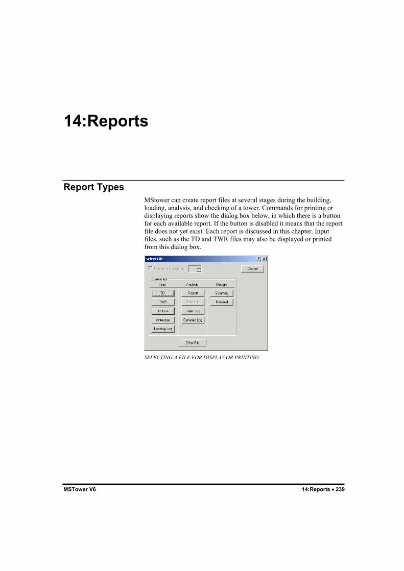
MSTower V6 14:Reports • 239
14:Reports
Report TypesMStower can create report files at several stages during the building,loading, analysis, and checking of a tower. Commands for printing ordisplaying reports show the dialog box below, in which there is a buttonfor each available report. If the button is disabled it means that the reportfile does not yet exist. Each report is discussed in this chapter. Inputfiles, such as the TD and TWR files may also be displayed or printedfrom this dialog box.
SELECTING A FILE FOR DISPLAY OR PRINTING

240 • 14:Reports MSTower V6
Display and Printing of FilesThe commands used for display and printing of files are:File > List/Edit FileThis command is used for displaying or editing a file in MStower’s texteditor, Msedit. It is possible to print files with this command but it isusually better to use the File > Print File command.File > Print FileThis command allows you to print files as neatly formatted reports. Theformatting is controlled by the Page Setup command, which allows youto set page orientation, margins, text size etc.File > Print PreviewThis command allows you to check a report and its formatting beforeprinting it.
Input/Analysis ReportThe Input/Analysis report is obtained at any stage by selecting theReports > Input/Analysis command. The dialog below then allows youto select the items you require in the report.
SELECTING REPORT OPTIONS
The Input/Analysis report is not available if you attempt to includereactions after gust factoring. To obtain the reactions after gust factoringyou must use theMember Check > Reactions command.

MSTower V6 14:Reports • 241
Error ReportThe Error report file, containing a list of geometry errors, is createdautomatically when errors are detected prior to analysis. TheAnalysis > Check Input command will also create this report file whenerrors are detected.
Error Report File
Microstran consistency checkJob: "XM3H" checked on 31-OCT-05 12:48:44------------------------------------------Error: member 1 property 111 undefinedError: member 2 property 111 undefinedError: member 3 property 111 undefinedError: member 4 property 111 undefinedError: member 25 property 8 undefinedError: member 26 property 8 undefinedError: member 41 property 111 undefinedError: member 42 property 111 undefinedError: member 43 property 111 undefinedError: member 44 property 111 undefinedShortest member: 25, length: 1.2673Longest member: 126, length: 3.583024 error(s), 0 warning(s)----- end of report -----
Static LogThe static log is a file created during linear or non-linear analysis thatlists several analysis parameters, including the condition number, ameasure of the numerical quality of the analysis.
Dynamic LogThe dynamic log is a file created during dynamic analysis that listsseveral analysis parameters, including the natural vibration modefrequencies.
Design SummaryThe design summary report file contains a summary of the results of anymember checking operation including those performed by theMember Check > Reactions andMember Check > Ancillary Rotations commands.It reports the critical load case and condition for the various memberclasses in each panel. It also contains a table of quantities and may noteany geometric or other problems encountered during the checkingprocess. Where possible, symbols similar to those in the particular codeof practice to which the check is done are used in the report.

242 • 14:Reports MSTower V6
Detailed Design ReportThe detailed design report is automatically produced by the memberchecking modules. It reports the information for all load cases and forevery member in the tower. It may be used to check the calculations forany member but is generally too voluminous to print.
Reaction ReportThe reaction report file is created by theMember Check > Reactions command and appended to the DesignSummary report. It contains the reactions at the tower supports in theglobal axes and also transformed into the direction of the individual legaxes.
Rotation ReportThe rotation report file is created by theMember Check > Ancillary Rotations command and appended to theDesign Summary report. It is in two sections:• A rotation envelope giving maximum rotations about the global axes
for the selected load cases. These rotations are computed byconsidering the displacement of a plane through the leg nodes at thetop of each panel.
• The rotation of each large ancillary for each selected load case. Therotations are computed by considering the displacement of a planethrough the first three attachment nodes and are given in the axes ofthe ancillary.
The tabulated rotations are those due to deflection of the tower. They donot account for any deflection in the ancillary mounting items.

MSTower V6 15:Examples • 243
15:Examples
GeneralUse the following procedure to run an MStower job:1. Start MStower (see “Starting MStower” on page 11).2. Select the File > Open command and in the dialog box browse to
the Examples folder (see “Folders” on page 10). Choose one of theexample jobs, say TWEX1, and then click the Open button. Thetower should now be displayed – if not, select the Tower > BuildTower > Process Tower Data File command
3. Select the Tower > Build/Load/Analyse command.4. Close the analysis window when it displays “Linear analysis
completed”.5. If checking to BS 8100 select the Tower > Gust Factor command.6. Select the appropriate design code on the Member Check menu. If
checking to BS 8100, select only the first load case of each set ofcombinations as the results of the gust factoring and square root ofthe sum of the squares is written to this case.
7. Select the Results > Design Ratios command and the structure willbe displayed with overstressed members colored red.
8. To display the results of the member checking select the File >List/Edit command and then click either the Summary or Detailedbutton. The selected report file will now be displayed in the MsEdittext editor. You may use the File > Print Preview command to seeeach page of the report, exactly how it will appear when printed.
To run a mast job, proceed as set out above but when the Analysis LoadCases dialog box appears select Case 100 and all combination loadcases. When the Non Linear Analysis Parameters dialog box is displayedclick OK to accept the default values. The non linear analysis requiredfor masts takes longer than linear analysis.To run an existing MStower Version 4 job select the File > Newcommand, confirm the job file folder, enter the job name and thenproceed from Step 3, above.

244 • 15:Examples MSTower V6
When MStower is installed a number of job files are located in theExamples folder (see “Folders” on page 10). These jobs, which havesimplified data and loading files, are described below. Plots are shownon the previous page. Analysis of masts requires the catenary cableoption and non-linear analysis.Example TowersTWEX1 – A plain tower to illustrate member checking to BS 8100.TWEX2 – A communications tower composed of standard panels with anumber of linear, large, and face ancillaries.TWEX4 – A power line tower using UDPs with asymmetrical cross-arms.TWEX7 – A 152 m guyed mast to illustrate member checking toBS 8100 Part 3.

MSTower V6 15:Examples • 245
EXAMPLE TOWERS

246 • 15:Examples MSTower V6
TWEX1This example is a plain tower for checking to BS 8100.
TWEX1
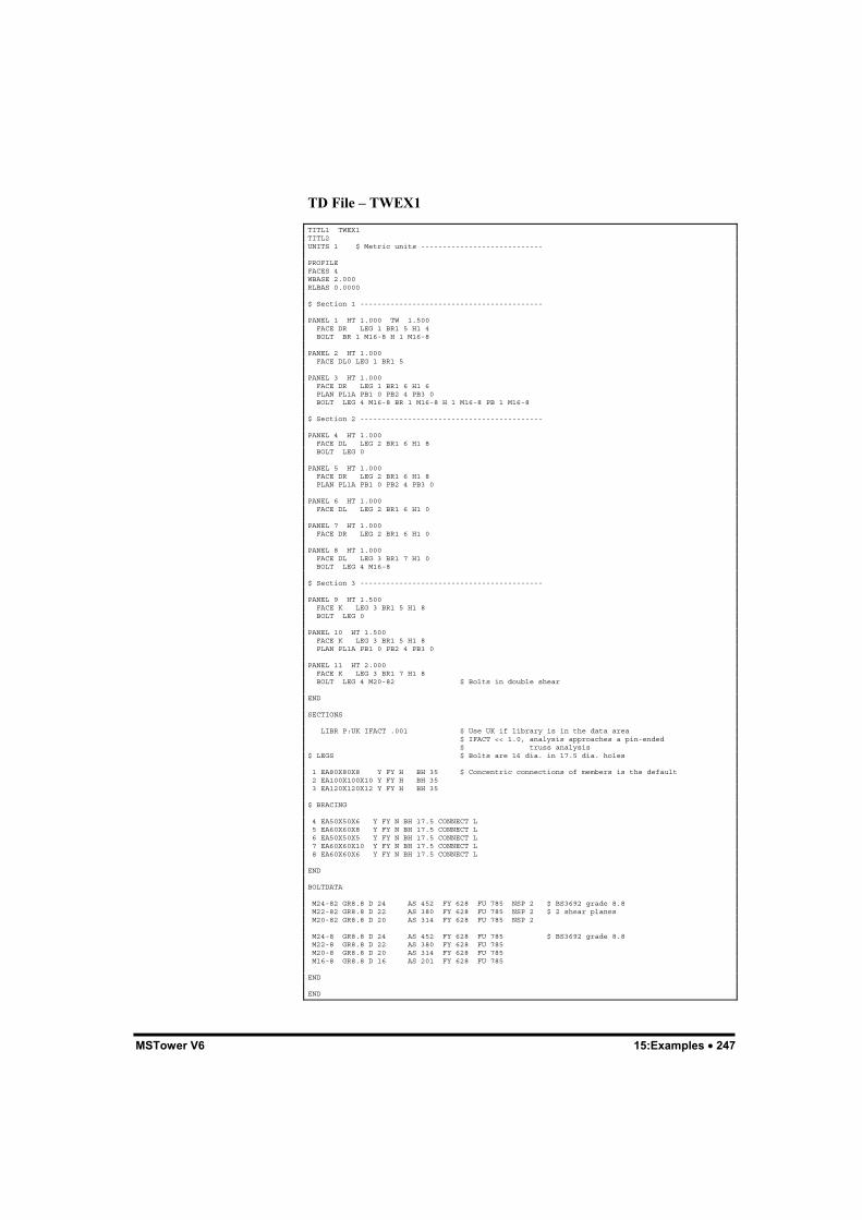
MSTower V6 15:Examples • 247
TD File – TWEX1
TITL1 TWEX1TITL2UNITS 1 $ Metric units ----------------------------
PROFILEFACES 4WBASE 2.000RLBAS 0.0000
$ Section 1 ------------------------------------------
PANEL 1 HT 1.000 TW 1.500 FACE DR LEG 1 BR1 5 H1 4 BOLT BR 1 M16-8 H 1 M16-8
PANEL 2 HT 1.000 FACE DL0 LEG 1 BR1 5
PANEL 3 HT 1.000 FACE DR LEG 1 BR1 6 H1 6 PLAN PL1A PB1 0 PB2 4 PB3 0 BOLT LEG 4 M16-8 BR 1 M16-8 H 1 M16-8 PB 1 M16-8
$ Section 2 ------------------------------------------
PANEL 4 HT 1.000 FACE DL LEG 2 BR1 6 H1 8 BOLT LEG 0
PANEL 5 HT 1.000 FACE DR LEG 2 BR1 6 H1 8 PLAN PL1A PB1 0 PB2 4 PB3 0
PANEL 6 HT 1.000 FACE DL LEG 2 BR1 6 H1 0
PANEL 7 HT 1.000 FACE DR LEG 2 BR1 6 H1 0
PANEL 8 HT 1.000 FACE DL LEG 3 BR1 7 H1 0 BOLT LEG 4 M16-8
$ Section 3 ------------------------------------------
PANEL 9 HT 1.500 FACE K LEG 3 BR1 5 H1 8 BOLT LEG 0
PANEL 10 HT 1.500 FACE K LEG 3 BR1 5 H1 8 PLAN PL1A PB1 0 PB2 4 PB3 0
PANEL 11 HT 2.000 FACE K LEG 3 BR1 7 H1 8 BOLT LEG 4 M20-82 $ Bolts in double shear
END
SECTIONS
LIBR P:UK IFACT .001 $ Use UK if library is in the data area $ IFACT << 1.0, analysis approaches a pin-ended $ truss analysis$ LEGS $ Bolts are 16 dia. in 17.5 dia. holes
1 EA80X80X8 Y FY H BH 35 $ Concentric connections of members is the default 2 EA100X100X10 Y FY H BH 35 3 EA120X120X12 Y FY H BH 35
$ BRACING
4 EA50X50X6 Y FY N BH 17.5 CONNECT L 5 EA60X60X8 Y FY N BH 17.5 CONNECT L 6 EA50X50X5 Y FY N BH 17.5 CONNECT L 7 EA60X60X10 Y FY N BH 17.5 CONNECT L 8 EA60X60X6 Y FY N BH 17.5 CONNECT L
END
BOLTDATA
M24-82 GR8.8 D 24 AS 452 FY 628 FU 785 NSP 2 $ BS3692 grade 8.8 M22-82 GR8.8 D 22 AS 380 FY 628 FU 785 NSP 2 $ 2 shear planes M20-82 GR8.8 D 20 AS 314 FY 628 FU 785 NSP 2
M24-8 GR8.8 D 24 AS 452 FY 628 FU 785 $ BS3692 grade 8.8 M22-8 GR8.8 D 22 AS 380 FY 628 FU 785 M20-8 GR8.8 D 20 AS 314 FY 628 FU 785 M16-8 GR8.8 D 16 AS 201 FY 628 FU 785
END
END

248 • 15:Examples MSTower V6
TWR File – TWEX1
$ From FILE TWRSTD.TWR$ Prototype TWR file for square tower.
$ STATION$ HEIGHT$ NGR SP$ MAP No
$ STRUCTURE
$ TYPE:-$ MANUFACTURERS:-$ ANCILLARIES Drg$ Amendments$$ CAD REF$ STRUCTURAL DRAWINGS :-$
PARAMETERS ANGN 45.0 CODE BS8100 $ Wind profile to this code ICE RO 0.0 RW 0.0 $ ALTOP 0 $ Site + tower height PSF-V 1.20 $ PSF-M 1.20 $ VB 30.0 MEAN $ Site wind speed - mean hourly for BS 8100 OVERLAP 1
END
TERRAIN ANGLE 0 TCAT 2 $ HH 0.0 BETAH 0.0 XLEE 0.0
END
LOADS CASE 100 Weight of tower plus ancillaries DL $ TODO - any additional NDLDs go here
CASE 200 wind at 180 to X axis WL ANGLX 180.0 NOICE
CASE 220 wind at 225 to X axis WL ANGLX 225.0 NOICE
CASE 240 wind at 270 to X axis WL ANGLX 270.0 NOICE
CASE 500 Max. tower weight COMBIN 100 1.050
CASE 520 TENSION: wind at 180 to X axis COMBIN 100 0.900 COMBIN 200 1.000
CASE 540 COMPRES: wind at 180 to X axis COMBIN 100 1.050 COMBIN 200 1.000
CASE 560 TENSION: wind at 225 to X axis COMBIN 100 0.900 COMBIN 220 1.000
CASE 580 COMPRES: wind at 225 to X axis COMBIN 100 1.050 COMBIN 220 1.000
CASE 600 TENSION: wind at 270 to X axis COMBIN 100 0.900 COMBIN 240 1.000
CASE 620 COMPRES: wind at 270 to X axis COMBIN 100 1.050 COMBIN 240 1.000
END
ANCILLARIES
LARGE LIBR P:MS_ANC.LIB $ use MS_ANC.LIB if library is in DATA area
DISH-1 XA 1.0 YA 1.0 ZA 11 LIB SH1PR-6 ANG 0
LINEAR LIBR P:MS_LIN.LIB $ use MS_LIN.LIB if library in DATA area

MSTower V6 15:Examples • 249
fdrs XB .5 YB .5 ZB 0 XT .5 YT .5 ZT 11 LIB FDRS-SMALL
$ FDRSds XB 00.0 YB 00.0 ZB 00.0 XT 00.0 YT 00.0 ZT 00.0 LIB FDRS-SMALL
FACE
$ SCREEN6 FACE 1234 ZA 00.0 MASS 00 CN 0.0 AREA 0.0 FLAT
ENDEND
The member check summary report for TWEX1 is shown in thefollowing pages. The detailed report for this example is almost 100pages in length.

250 • 15:Examples MSTower V6

MSTower V6 15:Examples • 251

252 • 15:Examples MSTower V6

MSTower V6 15:Ancillary Programs • 253
15:Ancillary Programs
CTIDATACTIDATA generates a tower data (TD) file from a prototype TWR fileand Cti.csv database file.To run CTIDATA from the main menu select theTower > Load Tower > Process Ancillary DB File command.This command will not be available unless a tower geometry has beenbuilt and the CSV file exists in the data folder.The prototype TWR file, Ctistd.twr must be present in the data folderand the geometry of the structure must have been created.A tower loading file is output.When CTIDATA is run a number of dialog boxes are presented for youto choose codes and enter parameters that will be substituted into a copyof the prototype TWR file.A set of wind angle and load combinations is entered for generation of anew LOADS block. All wind load directions are referred to the tower Xaxis, simplifying the generation of face and corner winds. Any or all faceor corner wind directions may be chosen. In addition, for triangulartowers, winds parallel to faces may also be chosen.Any large ancillary data in the prototype file is replaced with dataderived from the CSV file.If the tower loading file exists before CTIDATA is run, only the largeancillary data will be replaced. The PARAMETERS and LOADS blockswill be unchanged and previously existing ancillary loads will becommented out and remain in the file for possible future reference.Arrangements may be made to customize this program to userrequirements.

254 • 15:Ancillary Programs MSTower V6

MStower V6 Index • 255
Index
AACCEL keyword 168Accelerator keys 133Additional member temperatures
167Additional node loads 167AICE keyword 174, 178ALTOP keyword 150AMASS keyword 175Analyse menu 26Analysis
Buckling 204Dynamic 207Elastic critical load 204Linear 197Non-linear 197Response spectrum 209Second-order 197
ANCILLARY block 171, 186, 188Ancillary libraries 186Ancillary rotations 242ANGLE keyword 153, 154, 155,
156, 157, 158, 163ANGLX keyword 163ANGN keyword 149Archive file 41AREA keyword 174, 177ARES keyword 177ATTACH keyword 176Attributes toolbar 34AutoCAD 192Axes 40
BBARE keyword 167Basic velocity 152BH keyword 56Blocks
ANCILLARY 171BOLTDATA 58
COMPONENT 45EXTERNAL 162GUYLIST 161GUYS 54LOADS 162MATERIAL 58NODENAME 160PANEL 170PARAMETERS 148PROFILE 46PVEL_GUY 160PVEL_MAST 160SECTIONS 55SUPPORTS 53TERRAIN 153Title 45VELOCITY 159
BOLT keyword 47BOLTDATA block 58Boundary 139Break line 129BRES keyword 177Buckling 204
CCable 200CAD DXF 191CN keyword 178CODE keyword 149COEFFICIENTS block 187, 189Colors 14COMBIN keyword 170Combination load cases 170Compiling a library 236COMPONENT block 45Condition number 241Configuration 14CONNECT keyword 56Connections 60Context menu 12, 128, 134COORD keyword 53Coordinate systems 40, 129Coordinates 128CROSS keyword 51, 163Cross-arms 77, 115Crossing window 133Ctrl+A 133, 134Ctrl+C 133Ctrl+V 133Ctrl+X 133Ctrl+Y 133Ctrl+Z 133Cursor 132Customize 37
256 • Index MStower V6
Cylindrical coordinates 129
DD & V face panels 78Damping 152Data tip 21Dead loads 166Deflections 182Delete 133DENS keyword 58, 166Design summary 241Design type 230Detailed design report 242Detailing 192, 228Display toolbar 33DLM face panels 102DLM2 face panels 102DM face panel 100DM2 face panel 100DMH face panels 101DMH2 face panels 101Double-click 13, 134Draw toolbar 34Drawing 128Drawing plane 131Duplicate members 131Duplicate nodes 131Dynamic amplification 183Dynamic analysis 207Dynamic log 241
EE keyword 58Earthquake loading 168ECL 204Editing a section library 236Effective length 204Elastic critical load analysis 204ELF1 keyword 169EMA2 keyword 169E-mail 19EMF 193End line 130EQ keyword 168, 169Error report 241Errors 41Example 65, 66, 67, 68, 70, 140Examples 11Explorer 13Export
Archive file 41DXF 191SDNF 192
EXTERN keyword 164EXTERNAL block 162EXTFACT keyword 162Extra Buttons toolbar 36
FF5 133Face ancillaries 171, 174FACE keyword 48, 174Face panels 72Face Panels
D & V 78DLM 102DLM2 102DM 100DM2 100DMH 101DMH2 101K 84KXM 103KXM2 103M 94W 96X 79XDM 99XDMA 99XM 98XMA 98
Face results 178FACES keyword 46FACT keyword 173, 175File menu 22File type 13Fixed-end actions 199, 200Folders 10Frame buckling 203FREQ keyword 151
GGFACT keyword 164Graphics input 122, 127, 140GRAV keyword 151Gust factor correction 179Guy library 61Guyed mast patch loadings 165GUYLIST block 161GUYS block 54GUYS keyword 61
HHardware lock 9

MStower V6 Index • 257
Help About dialog box 19Help menu 31Help toolbar 33Hip bracing 77, 112HIP keyword 50Home 133Hot-links 19
IICE keyword 150, 163, 166Ice loads 166Icon 187Import
Archive file 124DXF 192UDP 128
Input load case 21Input/Analysis report 240Instability 203Installation 9Insulators 171, 177INSULATORS keyword 177Interruptible commands 132
JJob size 14Joints 60
KK face panels 84KXM face panel 103KXM2 face panel 103
LLambda 204Large ancillaries 171, 175LARGE keyword 175Launch 13LIB keyword 54, 172, 175LIBR keyword 55Library
Ancillary 186Section 229
Library Viewer 237Limit 138Linear analysis 197Linear ancillaries 171, 172LINEAR keyword 172Loads
Additional member temperatures167
Additional node 167Dead 166Guyed mast patch 165Ice 166Miscellaneous 167Wind 163
LOADS block 162Local axes 40, 57
MM face panels 94Main toolbar 31Main window 21MASS keyword 174, 178MATERIAL block 58MCAP keyword 49MEMB keyword 119Member axes 40Member checking 41Member Checking menu 25Member orientation 51Member properties 135Member/face table 178Members
Non-Linear 200Menu bar 21Menus 21MI keyword 167Miscellaneous loads 167Modifying a UDP 123Monopole 104MsEdit 236MTMP keyword 168Multiple selection 136
NNDLD keyword 167NODE keyword 119, 177Node properties 135NODENAME block 160NOICE keyword 163Non-linear analysis 197NOPATCH keyword 164NOWIND keyword 167
OOK/Cancel toolbar 35Orientation 57Output 178

258 • Index MStower V6
Output window 21, 37
PPage Setup 16PANEL block 170PANEL keyword 47PARAMETERS block 148PATCH keyword 164P-delta effect 198, 199P-Delta effect 198, 199Plan bracing 70, 76, 105PLAN keyword 50Pole
SH3 104SH4 104
Pop-up menu 12, 134Printing in MStower 15PROFILE block 46Prompt 21PVEL_GUY block 160PVEL_MAST block 160
QQuery menu 29
RReaction report 242Rectangular coordinates 129Reference axis 40Reference node 40, 51, 57Relative coordinates 129Report
Design summary 241Detailed design 242Dynamic log 241Error 241Reaction 242Rotation 242Static log 241
Report files 228Reports 239Reports menu 27Residual stress code 231RESISTANCE keyword 177Resistance table 178Resistances 176Response spectrum analysis 209Results menu 27Results toolbar 35Right-click 128, 134Rotation report 242
RotationsAncillary 242
SSchifflerized angles 231SDAMP keyword 151SDNF 192Second-order analysis 197Section alias file 193Section axis 57Section library 18, 229Section Library Manager 233Section mnemonic 229Section name 229Section properties 235Sections 41SECTIONS block 55Select members 133Select nodes 133Selection box 133SELF keyword 173Serial number 19SH3 pole 104SH4 pole 104SHADE keyword 173, 175SHEFF keyword 173, 175Shortcut 13Shortcut keys 133Show menu 28SMEAR keyword 164Snap mode 21, 130
Grid 130Intersection 130Mid/End 130Nearest 130Orthogonal 130Perpendicular 130
Space 133Spherical coordinates 129Static log 241Status bar 21Steel detailing 192, 228Steel grade 231Steel poles 62Stretch 137Structure menu 25Subset 138Support 19SUPPORTS block 53
TTD file 39, 43, 44, 65, 66, 67, 68, 70Technical support 19

MStower V6 Index • 259
TEMP keyword 168Tension-only 200TERRAIN block 153Text editor 39Text file 39, 229Title block 45TMASS keyword 176Toolbars 21, 36
Reset 36Tower menu 24TRES keyword 177Troubleshooting 203TWR file 39
UUDP example 140UDP file 39UDP file names 125UDP from Microstran 124UDP keyword 118Unequal leg length 123UNICE keyword 164, 167Units 40
VVB keyword 150VELOCITY block 159Velocity table 178View menu 23View toolbar 32
WW face panels 96Web update 20WIND keyword 166Wind load cases 163Wind resistance 179Window 138Window menu 30
XX face panels 79XDM face panel 99XDMA face panel 99XM face panel 98XMA face panel 98Xsteel 192, 228
YYield stress 231
ZZF keyword 159ZGUST keyword 164, 179ZGUST2 keyword 164ZREF keyword 161

260 • Index MStower V6