mt t rl k mralcm - metra online · 99-3045 ensamble del kit (figura a) (figura b) (figura c)...
TRANSCRIPT

METRA. The World’s best kits.™ metraonline.com © COPYRIGHT 2004-2015 METRA ELECTRONICS CORPORATION
REV.
11/
6/20
15
INST
99-3
045
Installation instructions for part 99-3045
CAUTION! Metra recommends disconnecting the negative bat-tery terminal before beginning any installation, unless the vehicle manufacturer recommends against so. Please check with your local Dealership for more information. All accessories, switches, climate controls panels, and especially air bag indicator lights must be con-nected before reconnecting the battery or cycling the ignition. Also, do not remove the factory radio with the key in the on position, or the vehicle running. It would be best to remove the key from the ignition and then wait a few seconds before removing the factory radio.
• ISO DIN radio provision with pocket• ISO DDIN radio provision
• A) Radio trim panel • B) Radio brackets • C) Pocket • D) (4) #8 x 3/8” Phillips screws
KIT FEATURES
KIT COMPONENTS
WIRING & ANTENNA CONNECTIONS (sold separately)Wiring Harness: • 70-1858
Antenna Adapter: • 40-GM10
• Panel removal tool • Phillips screwdriver • Socket wrenchTOOLS REQUIRED
GM Small Truck 1994-199799-3045 Dash Disassembly ..................................................2
Kit Assembly
– ISO DIN radio provision with pocket ...................... 3
– ISO DDIN radio provision ...................................... 3
Table of Contents
B C DA
APPLICATIONSCHEVROLET Blazer 1995-1997S-10 pickup 1994-1997
GMCJimmy 1995-1997 Sonoma 1994-1997
IsuzuHombre 1996-1997
OldsmobileBravada 1995-1997

99-3045
2
1. Remove (2) screws above the speedometer cluster.
2. Remove the ashtray, and then (1) screw exposed in the ashtray cavity.
3. Remove (2) screws from the lower steering column panel, and then loosen the panel at the top.
Note: The panel does not have to be removed.
4. Unclip the dash trim bezel, disconnect the light switch wiring, and then remove the bezel.
5. Remove (4) screws securing the climate control panel, and then move the panel slightly out of the way to expose the radio screws.
6. Remove (4) screws securing the radio, unplug the connectors, and then remove the radio.
Continue to kit assembly
Dash Disassembly
(Figure A)

99-3045
Kit Assembly
(Figure A)
(Figure B)
(Figure C)
(Figure A)
(Figure B)
ISO DIN radio provision with pocket
1. Secure the radio brackets to the pocket with the (4) #8 x 3/8” Phillips screws provided. (Figure A)
2. Remove the metal DIN sleeve and trim ring from the aftermarket radio.
3. Slide the radio into the pocket/bracket assembly, and then secure with the screws included with radio. (Figure B).
4. Locate the factory wiring harness and antenna connector in the dash and complete all necessary connections to the radio. Metra recommends using the proper mating adapter from Metra or AXXESS. Reconnect he negative battery terminal and test the radio for proper operation.
5. Attach the radio trim panel to the completed assembly, and then reassemble the dash in reverse of disassembly. (Figure C)
ISO DDIN radio provision
1. Secure the radio brackets to the radio with the screws included with the radio. (Figure A)
2. Locate the factory wiring harness and antenna connector in the dash and complete all necessary connections to the radio. Metra recommends using the proper mating adapter from Metra or AXXESS. Reconnect the negative battery terminal and test the radio for proper operation.
3. Attach the radio trim panel to the completed assembly, and then reassemble the dash in reverse of disassembly. (Figure B)
3

METRA. The World’s best kits.™ metraonline.com © COPYRIGHT 2004-2015 METRA ELECTRONICS CORPORATION
REV.
11/
6/20
15
INST
99-3
045
KNOWLEDGE IS POWEREnhance your installation and fabrication skills by enrolling in the most recognized and respected mobile electronics school in our industry.Log onto www.installerinstitute.com or call 800-354-6782 for more information and take steps toward a better tomorrow.
Metra recommends MECP certified technicians
Installation instructions for part 99-3045
IMPORTANTIf you are having difficulties with the installation of this product, please call our Tech Support line at 1-800-253-TECH. Before doing so, look over the instructions a second time, and make sure the installation was performed exactly as the instructions are stated. Please have the vehicle apart and ready to perform troubleshooting steps before calling.

METRA. The World’s best kits.™ metraonline.com © COPYRIGHT 2004-2015 METRA ELECTRONICS CORPORATION
REV.
11/
6/20
15
INST
99-3
045
Instrucciones de instalación para la pieza 99-3045
¡PRECAUCIÓN! Meta recomienda desconectar la terminal negativa de la batería antes de iniciar cualquier instalación, a menos que el fabricante del vehículo recomiende lo contrario. Verifique con su concesionario local si existe más información. Todos los accesorios, interruptores, paneles de controles de clima y especialmente las lu-ces del indicador de las bolsas de aire deben estar conectados antes de reconectar la batería o ciclar la ignición. Además, no quite el radio de fábrica con la llave en la posición de encendido ni con el vehículo funcionando. Sería mejor retirar la llave de la ignición y esperar unos cuantos segundos antes de quitar el radio de fábrica.
• Provisión de radio ISO DIN con cavidad• Provisión de radio ISO DDIN
• A) Panel de moldura de radio • B) Soportes de radio • C) Cavidad • D) (4) Tornillos Phillips #8 x 3/8”
CARACTERÍSTICAS DEL KIT
COMPONENTES DEL KIT
CABLEADO Y CONEXIONES DE ANTENA (se venden por separado)Arnés de cableado: • 70-1858
Adaptador de antena: • 40-GM10
• Herramienta para quitar paneles • Destornillador Phillips • llave de tubo
HERRAMIENTAS REQUERIDAS
GM Camión Pequeño 1994-199799-3045 Desmontaje tablero ................................................2
Ensamble del kit
– Provisión de radio ISO DIN con cavidad ................ 3
– Provisión de radio ISO DDIN ................................. 3
Indice
B C DA
APLICACIONESCHEVROLET Blazer 1995-1997S-10 pickup 1994-1997
GMCJimmy 1995-1997 Sonoma 1994-1997
IsuzuHombre 1996-1997
OldsmobileBravada 1995-1997
99-3045
2
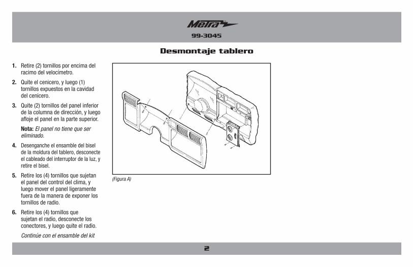
1. Retire (2) tornillos por encima del racimo del velocímetro.
2. Quite el cenicero, y luego (1) tornillos expuestos en la cavidad del cenicero.
3. Quite (2) tornillos del panel inferior de la columna de dirección, y luego afloje el panel en la parte superior.
Nota: El panel no tiene que ser eliminado.
4. Desenganche el ensamble del bisel de la moldura del tablero, desconecte el cableado del interruptor de la luz, y retire el bisel.
5. Retire los (4) tornillos que sujetan el panel del control del clima, y luego mover el panel ligeramente fuera de la manera de exponer los tornillos de radio.
6. Retire los (4) tornillos que sujetan el radio, desconecte los conectores, y luego quite el radio.
Continúe con el ensamble del kit
Desmontaje tablero
(Figura A)
99-3045
Ensamble del kit
(Figura A)
(Figura B)
(Figura C)
(Figura A)
(Figura B)
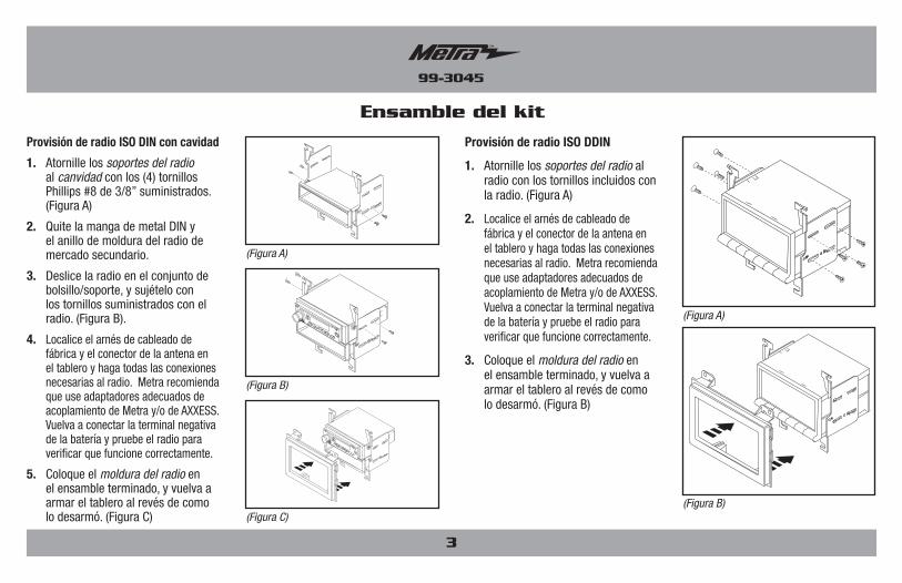
Provisión de radio ISO DIN con cavidad
1. Atornille los soportes del radio al canvidad con los (4) tornillos Phillips #8 de 3/8” suministrados. (Figura A)
2. Quite la manga de metal DIN y el anillo de moldura del radio de mercado secundario.
3. Deslice la radio en el conjunto de bolsillo/soporte, y sujételo con los tornillos suministrados con el radio. (Figura B).
4. Localice el arnés de cableado de fábrica y el conector de la antena en el tablero y haga todas las conexiones necesarias al radio. Metra recomienda que use adaptadores adecuados de acoplamiento de Metra y/o de AXXESS. Vuelva a conectar la terminal negativa de la batería y pruebe el radio para verificar que funcione correctamente.
5. Coloque el moldura del radio en el ensamble terminado, y vuelva a armar el tablero al revés de como lo desarmó. (Figura C)
Provisión de radio ISO DDIN
1. Atornille los soportes del radio al radio con los tornillos incluidos con la radio. (Figura A)
2. Localice el arnés de cableado de fábrica y el conector de la antena en el tablero y haga todas las conexiones necesarias al radio. Metra recomienda que use adaptadores adecuados de acoplamiento de Metra y/o de AXXESS. Vuelva a conectar la terminal negativa de la batería y pruebe el radio para verificar que funcione correctamente.
3. Coloque el moldura del radio en el ensamble terminado, y vuelva a armar el tablero al revés de como lo desarmó. (Figura B)
3

METRA. The World’s best kits.™ metraonline.com © COPYRIGHT 2004-2015 METRA ELECTRONICS CORPORATION
REV.
11/
6/20
15
INST
99-3
045
KNOWLEDGE IS POWEREnhance your installation and fabrication skills by enrolling in the most recognized and respected mobile electronics school in our industry.Log onto www.installerinstitute.com or call 800-354-6782 for more information and take steps toward a better tomorrow.
Metra recomienda técnicos con certificación del Programa de Certificación en Electrónica Móvil (Mobile Electronics Certification Program, MECP).
EL CONOCIMIENTO ES PODERMejore sus habilidades de instalación y fabricación inscribiéndose en la escuela de dispositivos electrónicos móviles más reconocida y respetada de nuestra industria. Regístrese en www.installerinstitute.com o llame al 800-354-6782 para obtener más información y avance hacia un futuro mejor.
Instrucciones de instalación para la pieza 99-3045
IMPORTANTESi tiene dificultades con la instalación de este producto, llame a nuestra línea de soporte técnico al 1-800-253-TECH. Antes de hacerlo, revise las instrucciones por segunda vez y asegúrese de que la instalación se haya realizado exactamente como se indica en las instrucciones. Por favor tenga el vehículo desarmado y listo para ejecutar los pasos de resolución de problemas antes de llamar.