m.tech-cad cam
DESCRIPTION
syllabus of b.s.a.u universityTRANSCRIPT
UNIVERSITY VISION AND MISSION
VISION
B.S. Abdur Rahman Institute of Science & Technology aspires to be a leader inEducation, Training and Research in Engineering, Science, Technology andManagement and to play a vital role in the Socio-Economic progress of the Country.
MISSION
• To blossom into an internationally renowned University.
• To empower the youth through quality education and to provide professionalleadership.
• To achieve excellence in all its endeavors to face global challenges.
• To provide excellent teaching and research ambience.
• To network with global Institutions of Excellence, Business, Industry andResearch Organizations.
• To contribute to the knowledge base through Scientific enquiry, Applied Researchand Innovation.

2
M.Tech. CAD CAM
VISION AND MISSION OF THEDEPARTMENT OF MECHANICAL ENGINEERING
VISION
To excel in providing quality education and training through Undergraduate andPostgraduate programs and carryout quality Research in the field of MechanicalEngineering
MISSION
• To provide a good learning experience through appropriate design of curriculumand syllabi that facilitate students to gain thorough understanding of thefundamental concepts and applications in Mechanical Engineering
• To equip students to solve challenging problems in Mechanical Engineeringand related areas taking in to account their impact on the society
• To facilitate students to develop good communication, leadership and managerialskills through team approach in conducting experiments and projects
• To pursue academic and collaborative research activities with industry and otherresearch institutions ensuring high quality in publications and other researchoutputs

4
M.Tech. CAD CAM

PROGRAMME EDUCATIONAL OBJECTIVES ANDOUTCOMES
M.Tech. (CAD-CAM)PROGRAMME EDUCATIONAL OBJECTIVES
• To provide a holistic approach in learning through well designed coursesinvolving fundamental concepts and state-of-the-art techniques in the field ofCAD – CAM.
• To equip the graduates, with knowledge and skill to undertake design, analysis,evaluation of systems, processes and components.
• To supplement course work through seminars, workshops, case studies,and through paper presentation.
• To inculcate research culture by way of solving typical problems, Projectworks from real life situation and innovative assignments.
• To develop team spirit, problem solving skill, and appreciation for ethical andsocial relevance of the technologies used.
PROGRAMME OUTCOMES
On completion of program, the graduates will
• have sound conceptual knowledge and skill in the area of design andmanufacturing.
• be able to design, analyze and manufacture real life systems andcomponents.
• have capability to use latest software in the area of computer aided engineeringfor modeling, analysis and manufacture.
• be able to undertake academic and applied research and address open endedproblems.
• have the ability to discharge professional, social & economic responsibilitiesethically.

6
M.Tech. CAD CAM

REGULATIONS 2013FOR
M.TECH. DEGREE PROGRAMMES

8
M.Tech. CAD CAM

B.S. ABDUR RAHMAN UNIVERSITY, CHENNAI 48.REGULATIONS - 2013 FOR M.TECH / MCA / M.Sc.
DEGREE PROGRAMMES1.0 PRELIMINARY DEFINITIONS AND NOMENCLATURE
In these Regulations, unless the context otherwise requires
i) "Programme" means Post Graduate Degree Programme (M.Tech./ MCA /M.Sc.)
ii) "Course" means a theory or practical subject that is normally studied in asemester, like Applied Mathematics, Structural Dynamics, Computer AidedDesign, etc.
iii) "University" means B.S.Abdur Rahman University, Chennai, 600048.
iv) "Institution" unless otherwise specifically mentioned as an autonomous oroff campus institution means B.S.Abdur Rahman University.
v) "Academic Council" means the Academic Council of this University.
vi) "Dean (Academic Affairs)" means Dean (Academic Affairs) of B.S.AbdurRahman University.
vii) "Dean (Student Affairs)" means Dean(Student Affairs) of B.S.Abdur RahmanUniversity.
viii) "Controller of Examinations" means the Controller of Examinations ofB.S.Abdur Rahman University who is responsible for conduct of examinationsand declaration of results.
2.0 PROGRAMMES OFFERED, MODE OF STUDY AND ADMISSIONREQUIREMENTS
2.1 P.G. Programmes Offered
The various P.G. Programmes and their modes of study are as follows:
Degree Mode of StudyM.Tech. Full Time
M.Tech. Part Time – Day / EveningM.C.A. Full Time
M. Sc. Full Time

10
M.Tech. CAD CAM
2.2 MODES OF STUDY
2.2.1 Full-time
Students admitted under "Full-Time" shall be available in the Institution duringthe complete working hours for curricular, co-curricular and extra-curricularactivities assigned to them.
2.2.2 A full time student, who has completed all non-project courses desiring to dothe Project work in part-time mode for valid reasons, shall apply to the Dean(Academic Affairs) through the Head of the Department, if the student satisfiesthe clause 2.3.4 of this Regulation. Permission may be granted based onmerits of the case. Such conversion is not permitted in the middle of asemester.
2.2.3 Part time - Day time
In this mode of study, the students are required to attend classes for thecourses registered along with full time students.
2.2.4 Part time - Evening
In this mode of study, the students are required to attend normally classes inthe evening and on Saturdays, if necessary.
2.2.5 A part time student is not permitted to convert to full time mode of study.
2.3 ADMISSION REQUIREMENTS
2.3.1 Students for admission to the first semester of the Master's DegreeProgramme shall be required to have passed the appropriate degreeexamination of this University as specified in the Table shown for eligibleentry qualifications for admission to P.G. programmes or any other degreeexamination of any University or authority accepted by this University asequivalent thereto.
2.3.2 Eligibility conditions for admission such as class obtained, number of attemptsin the qualifying examination and physical fitness will be as prescribed bythis Institution from time to time.
2.3.3 All part-time students should satisfy other conditions regarding experience,sponsorship etc., which may be prescribed by this Institution from time totime.

11
M.Tech. CAD CAM
2.3.4 A student eligible for admission to M.Tech. Part Time / Day Time programmeshall have his/her permanent place of work within a distance of 65km fromthe campus of this Institution.
2.3.5 Student eligible for admission to M.C.A under lateral entry scheme shall berequired to have passed three year degree in B.Sc (Computer Science) /B.C.A / B.Sc (Information Technology)
3.0 DURATION AND STRUCTURE OF THE P.G. PROGRAMME
3.1 The minimum and maximum period for completion of the P.G. Programmesare given below:
Programme Min.No.of Semesters Max.No.of Semesters
M.Tech. (Full Time) 4 8
M.Tech. (Part Time) 6 12
M.C.A. (Full Time) 6 12
M.C.A. (Full Time) – (Lateral Entry) 4 8
M.Sc. (Full Time) 4 8
3.2 The PG. programmes consist of the following components as prescribed inthe respective curriculumi. Core coursesii. Elective coursesiii. Project work / thesis / dissertationiv. Laboratory Coursesv. Case studiesvi. Seminarsvii. Industrial Internship
3.3 The curriculum and syllabi of all PG. programmes shall be approved by theAcademic Council of this University.
3.4 The minimum number of credits to be earned for the successful completionof the programme shall be specified in the curriculum of the respectivespecialization of the P.G. programme.
3.5 Each academic semester shall normally comprise of 80 working days.Semester-end examinations will follow immediately after the last workingday.

12
M.Tech. CAD CAM
Sl.No.
Name of theDepartment
P.G. Programmesoffered
Qualifications foradmission
01. Civil EngineeringM.Tech. (Structural Engineering)
M.Tech. (Construction Engineeringand Project Management)
B.E / B.Tech. (Civil Engineering) /(Structural Engineering)
02. MechanicalEngineering
M.Tech. (Manufacturing Engineering)
M.Tech. CAD / CAM
B.E. / B.Tech. (Mechanical / Auto /Manufacturing / Production / Industrial /Mechatronics / Metallurgy / Aerospace/Aeronautical / Material Science /Marine Engineering)
03. Polymer Engineering M.Tech. (Polymer Technology)B.E./ B.Tech. degree Mech./Production/Polymer Science or Engg or Tech /Rubber Tech / M.Sc (Polymer Sc./Chemistry Appl. Chemistry)
04.Electrical andElectronicsEngineering
M.Tech. (Power Systems Engg) B.E / B.Tech (EEE / ECE / E&I / I&C /Electronics / Instrumentation)
05.Electronics andCommunicationEngineering
M.Tech. (Communication Systems)B.E / B.Tech (EEE/ ECE / E&I / I&C /Electronics / Instrumentation)
06.ECE Department jointlywith Physics Dept
M.Tech. (Optoelectronics and LaserTechnology)
B.E./B.Tech. (ECE / EEE / Electronics /EIE / ICE) M.Sc (Physics / MaterialsScience / Electronics / Photonics)
07.Electronics andInstrumentationEngineering
M.Tech. (Electronics andInstrumentation Engineering)
B.E./ B.Tech. (EIE/ICE/Electronics/ECE/EEE)
08. Computer Scienceand Engineering
M.Tech. (Computer Science andEngineering)
B.E. /B.Tech. (CSE/IT/ECE/EEE/EIE/ICE/Electronics) MCA
09InformationTechnology
M.Tech. (Information Technology)B.E /B.Tech. (IT/CSE/ECE/EEE/EIE/ICE/Electronics) MCA
ELIGIBLE ENTRY QUALIFICATIONS FOR ADMISSION TO P.G. PROGRAMMES
M.Tech. (Power Electronics & Drives)
M.Tech.(VLSI and Embedded Systems) B.E./ B.Tech. in ECE / Electronics /EIE / ICE / EEE
M.Tech. (Software Engineering) B.E. / B.Tech. (CSE / IT) MCA
M.Tech (Network Security)
B.E. /B.Tech. (CSE/IT/ECE/EEE/EIE/ICE/Electronics) MCA
M.Tech (Computer and PredictiveAnalytics)
M.Tech. (Information Security & DigitalForensics)
M.Tech. (Computer Science andEngineering with specialization in BigData Analytics)
M.Tech.(Signal Processing)

13
M.Tech. CAD CAM
Sl.No.
Name of theDepartment
P.G. Programmesoffered
Qualifications foradmission
ELIGIBLE ENTRY QUALIFICATIONS FOR ADMISSION TO P.G. PROGRAMMES
B.Sc (Chemistry) of B.Sc. (AppliedScience)
11 Mathematics
M.Sc. (Actuarial Science)Any Degree with Mathematics /Statistics as one of the Subjects ofStudy.
13 Chemistry M.Sc.(Chemistry)
10 Computer Applications
M.C.A.Bachelor Degree in any discipline withMathematics as one of the subjects(or) Mathematics at +2 level
M.Tech. (Systems Engineering andOperations Research) BE / B.Tech. (Any Branch) or M.Sc.,
(Maths / Physics / Statistics / CS / IT /SE) or M.C.A.M.Tech. (Data & Storage Management)
M.C.A. (Full Time) – (Lateral Entry)B.Sc Computer Science / B.ScInformation Technology / B.C.A
M.Sc. Mathematics B.Sc. (Mathematics)
B.Sc.(Physics / Applied Science /Electronics / Electronics Science /Electronics & Instrumentation)
12 Physics M.Sc.(Physics)
M.Sc. (Material Science)
14 Life Sciences
M.Sc. Molecular Biology &Biochemistry
M.Sc. Genetics
M.Sc. Biotechnology B.Sc. in any branch of Life Sciences
M.Sc. Microbiology
M.Sc. Bioscience
3.6 The curriculum of PG programmes shall be so designed that the minimumprescribed credits required for the award of the degree shall be within thelimits specified below:
Programme Minimum prescribed credit range
M.Tech. 75 to 85
M.C.A. 120 to 130
M.Sc. 75 to 85

14
M.Tech. CAD CAM
3.7 Credits will be assigned to the courses for all P.G. programmes as givenbelow:
* One credit for one lecture period per week
* One credit for one tutorial period per week
* One credit each for seminar/practical session/project of two or threeperiods per week
* One credit for two weeks of industrial internship.
3.8 The number of credits registered by a student in non-project semester andproject semester should be within the range specified below:
P.G. Programme Non-project Semester Project semester
M.Tech. (Full Time) 15 to 29 12 to 20
M.Tech. (Part Time) 6 to 18 12 to 16
M.C.A. (Full Time) 15 to 29 12 to 20
M.Sc. (Full Time) 15 to 25 12 to 20
3.9 The electives from the curriculum are to be chosen with the approval of theHead of the Department.
3.10 A student may be permitted by the Head of the Department to choose electivesoffered from other PG programmes either within the Department or fromother Departments up to a maximum of three courses during the period ofhis/her study, provided the Heads of the Departments offering such coursesalso agree.
3.11 To help the students to take up special research areas in their project workand to enable the department to introduce courses in latest/emerging areasin the curriculum, "Special Electives" may be offered. A student may bepermitted to register for a "Special Elective" up to a maximum of three creditsduring the period of his/her study, provided the syllabus of this course isrecommended by the Head of the Department and approved by the Chairman,Academic Council before the commencement of the semester, in which thespecial elective course is offered. Subsequently, such course shall be ratifiedby the Board of Studies and Academic Council.
3.12 The medium of instruction, examination, seminar and project/thesis/dissertation reports will be English.

15
M.Tech. CAD CAM
3.13 Industrial internship, if specified in the curriculum shall be of not less thantwo weeks duration and shall be organized by the Head of the Department.
3.14 PROJECT WORK/THESIS/DISSERTATION
3.14.1 Project work / Thesis / Dissertation shall be carried out under the supervisionof a qualified teacher in the concerned Department.
3.14.2 A student may however, in certain cases, be permitted to work for the projectin an Industrial/Research Organization, on the recommendation of the Headof the Department. In such cases, the project work shall be jointly supervisedby a faculty of the Department and an Engineer / Scientist from theorganization and the student shall be instructed to meet the faculty periodicallyand to attend the review committee meetings for evaluating the progress.
3.14.3 Project work / Thesis / Dissertation (Phase - II in the case of M.Tech.) shallbe pursued for a minimum of 16 weeks during the final semester, followingthe preliminary work carried out in Phase-1 during the previous semester.
3.14.4 The Project Report/Thesis / Dissertation report / Drawings preparedaccording to approved guidelines and duly signed by the supervisor(s) andthe Head of the Department shall be submitted to the concerned department.
3.14.5 The deadline for submission of final Project Report / Thesis / Dissertation iswithin 30 calendar days from the last working day of the semester in whichProject / Thesis / Dissertation is done.
3.14.6 If a student fails to submit the Project Report / Thesis / Dissertation on orbefore the specified deadline he / she is deemed to have not completed theProject Work / Thesis / dissertation and shall re-register the same in asubsequent semester.
3.14.7 A student who has acquired the minimum number of total credits prescribedin the Curriculum for the award of Masters Degree will not be permitted toenroll for more courses to improve his/her cumulative grade point average(CGPA).
4.0 CLASS ADVISOR AND FACULTY ADVISOR
4.1 CLASS ADVISOR
A faculty member will be nominated by the HOD as Class Advisor for thewhole class.

16
M.Tech. CAD CAM
He/she is responsible for maintaining the academic, curricular and co-curricular records of all students throughout their period of study.
4.2 FACULTY ADVISOR
To help the students in planning their courses of study and for generalcounseling on the academic programme, the Head of the Department of thestudents will attach a certain number of students to a faculty member of thedepartment who shall function as Faculty Advisor for the students throughouttheir period of study. Such Faculty Advisor shall offer advice to the studentson academic and personal matters, and guide the students in taking upcourses for registration and enrolment every semester.
5.0 CLASS COMMITTEE
5.1 Every class of the PG Programme will have a Class Committee constitutedby the Head of the Department as follows:
i. Teachers of all courses of the programme
ii. One senior faculty preferably not offering courses for the class, asChairperson.
iii. Minimum two students of the class, nominated by the Head of theDepartment.
iv. Class Advisor / Faculty Advisor of the class - Ex-Officio Member
v. Professor in-charge of the PG Programme - Ex-Officio Member.
5.2 The Class Committee shall be constituted by the respective Head of theDepartment of the students.
5.3 The basic responsibilities of the Class Committee are to review periodicallythe progress of the classes to discuss problems concerning curriculum andsyllabi and the conduct of classes. The type of assessment for the coursewill be decided by the teacher in consultation with the Class Committee andwill be announced to the students at the beginning of the semester. EachClass Committee will communicate its recommendations to the Head of theDepartment and Dean (Academic Affairs). The class committee, without thestudent members, will also be responsible for finalization of the semesterresults and award of grades.
5.4 The Class Committee is required to meet at least thrice in a semester, firstwithin a week of the commencement of the semester, second, after the first

17
M.Tech. CAD CAM
assessment and the third, after the semester-end examination to finalizethe grades.
6.0 COURSE COMMITTEE
Each common theory course offered to more than one group of studentsshall have a “Course Committee” comprising all the teachers teaching thecommon course with one of them nominated as Course coordinator. Thenomination of the Course coordinator shall be made by the Head of theDepartment / Dean (Academic Affairs) depending upon whether all theteachers teaching the common course belong to a single department or toseveral departments. The Course Committee shall meet as often as possibleand ensure uniform evaluation of the tests and arrive at a common schemeof evaluation for the tests. Wherever it is feasible, the Course Committeemay also prepare a common question paper for the test(s).
7.0 REGISTRATION AND ENROLMENT
7.1 For the first semester every student has to register and enroll for all thecourses.
7.2 For the subsequent semesters registration for the courses will be done bythe student during a specified week before the semester-end examination ofthe previous semester. The curriculum gives details of the core and electivecourses, project and seminar to be taken in different semester with the numberof credits. The student should consult his/her Faculty Adviser for the choiceof courses. The Registration form shall be filled in and signed by the studentand the Faculty Adviser.
7.3 From the second semester onwards all students shall pay the prescribedfees and enroll on a specified day at the beginning of a semester.
7.4 A student will become eligible for enrolment only if he/she satisfies clause 9and in addition he/she is not debarred from enrolment by a disciplinary actionof the Institution. At the time of enrolment a student can drop a courseregistered earlier and also substitute it by another course for valid reasonswith the consent of the Faculty Adviser. Late enrolment will be permitted onpayment of a prescribed fine up to two weeks from the date of commencementof the semester.

18
M.Tech. CAD CAM
7.5 Withdrawal from a course registered is permitted up to one week from thedate of the completion of the first assessment test.
7.6 Change of a course within a period of 15 days from the commencement ofthe course, with the approval of Dean (Academic Affairs), on therecommendation of the HOD, is permitted.
7.7 Courses withdrawn will have to be taken when they are offered next if theybelong to the list of core courses.
8.0 TEMPORARY BREAK OF STUDY FROM THE PROGRAMME
A student may be permitted by the Dean (Academic Affairs) to avail temporarybreak of study from the programme up to a maximum of two semesters forreasons of ill health or other valid grounds. Such student has to rejoin only inthe same semester from where he left. However the total duration forcompletion of the programme shall not exceed the prescribed maximumnumber of semesters (vide clause 3.1).
9.0 MINIMUM REQUIREMENTS TO REGISTER FOR PROJECT / THESIS /DISSERTATION
9.1 A student is permitted to register for project semester, if he/she has earnedthe minimum number of credits specified below:
Programme Minimum No. of credits to be earnedto enroll for project semester
M.Tech. (Full time) 18 (III semester)
M.Tech. (Part time) 18 (V semester)
M.C.A. (Full time) 45 (V semester)
M.C.A. (Full time) –(Lateral Entry) 22 (V semester)
M.Sc. (Full time) 30 (IV semester) if project is in IV semester
18 (III semester) if project is in III semester
9.2 If the student has not earned minimum number of credits specified, he/shehas to earn the required credits, at least to the extent of minimum creditsspecified in clause 9.1 and then register for the project semester.

19
M.Tech. CAD CAM
10.0 DISCIPLINE
10.1 Every student is required to observe discipline and decorous behavior bothinside and outside the campus and not to indulge in any activity, which willtend to bring down the prestige of the Institution.
10.2 Any act of indiscipline of a student reported to the Head of the Institution willbe referred to a Discipline and Welfare Committee for taking appropriateaction.
10.3 Every student should have been certified by the HOD that his / her conductand discipline have been satisfactory.
11.0 ATTENDANCE REQUIREMENT AND SEMESTER / COURSEREPETITION
Attendance rules for all Full-time programme and Part-time – Day-timeprogrammes are given in the following sub-clause.
11.1 A student should secure not less than 75% overall attendance in that semestertaking into account the total no. of periods in all courses put together attendedby the student as against the total no. of periods in all courses offered duringthat semester. If a student who could secure overall attendance between65% and 75% only in a particular semester due to medical reasons(hospitalization / accident / specific illness) or due to participation in the College/ University / State / National / International level sports events with priorpermission from the Officials concerned shall be given exemption from theprescribed attendance requirement and he / she shall be permitted to appearfor the current semester examinations.
The students who do not fulfill the above attendance requirement willnot be permitted to write the semester end examination and will not bepermitted to move to next semester. Such students should repeat allthe courses of the semester in the next Academic year.
11.2 The faculty member of each course shall furnish the cumulative attendancedetails to the class advisor. The class advisor will consolidate and furnishthe list of students who have earned less than 75% overall attendance, to theDean (Academic Affairs) through the Head of the Department / School Dean.Thereupon, the Dean (Academic Affairs) shall issue orders preventingstudents from appearing for the semester end examination of all the coursesof that semester.

20
M.Tech. CAD CAM
11.3 A student who is awarded “U” grade in a course will have the option of eitherto write semester end arrear examination at the end of the subsequentsemesters, or to redo the course whenever the course is offered. Marksearned during the redo period in the continuous assessment for the course,will be used for grading along with the marks earned in the semester-end(re-do) examination. If any student obtained “U” grade, the marks earnedduring the redo period for the continuous assessment for that course will beconsidered for further appearance as arrears.
11.4 If a student with “U” grade prefers to redo any particular course fails to earnthe minimum 75% attendance while doing that course, then he/she will notbe permitted to write the semester end examination and his / her earlier ‘U’grade and continuous assessment marks shall continue.
12.0 ASSESSMENTS AND EXAMINATIONS
12.1 The following rule shall apply to the full-time and part-time PG programmes(M.Tech./ M.C.A. / M.Sc.)
For lecture-based courses, normally a minimum of two assessments will bemade during the semester. The assessments may be combination of testsand assignments. The assessment procedure as decided in the ClassCommittee will be announced to the students right from the beginning of thesemester by the course teacher.
12.2 There shall be one examination of three hours duration, at the end of thesemester, in each lecture based course.
12.3 The evaluation of the Project work will be based on the project report and aViva-Voce Examination by a team consisting of the supervisor concerned,an Internal Examiner and External Examiner to be appointed by the Controllerof Examinations.
12.4 At the end of industrial internship, the student shall submit a certificate fromthe organization and also a brief report. The evaluation will be made basedon this report and a Viva-Voce Examination, conducted internally by aDepartmental Committee constituted by the Head of the Department.
13.0 WEIGHTAGES
13.1 The following shall be the weightages for different courses:

21
M.Tech. CAD CAM
i) Lecture based courseTwo continuous assessments - 50%Semester-end examination - 50%
ii) Laboratory based coursesLaboratory work assessment - 75%Semester-end examination - 25%
iii) Project workPeriodic reviews - 50%Evaluation of Project Report by External Examiner - 20%Viva-Voce Examination - 30%
13.2 Appearing for semester end examination for each course (Theory andPractical) is mandatory and a student should secure a minimum of 40%marks in semester end examination for the successful completion of thecourse.
13.3 The markings for all tests, tutorial, assignments (if any), laboratory work andexaminations will be on absolute basis. The final percentage of marks iscalculated in each course as per the weightages given in clause 13.1.
14.0 SUBSTITUTE EXAMINATION
14.1 A student who has missed for genuine reasons any one of the threeassessments including semester-end examination of a course may bepermitted to write a substitute examination. However, permission to take upa substitute examination will be given under exceptional circumstances, suchas accident or admissions to a hospital due to illness, etc.
14.2 A student who misses any assessment in a course shall apply in a prescribedform to the Dean (Academic Affairs) through the Head of the departmentwithin a week from the date of missed assessment. However the substitutetests and examination for a course will be conducted within two weeks afterthe last day of the semester-end examinations.
15.0 COURSEWISE GRADING OF STUDENTS AND LETTER GRADES
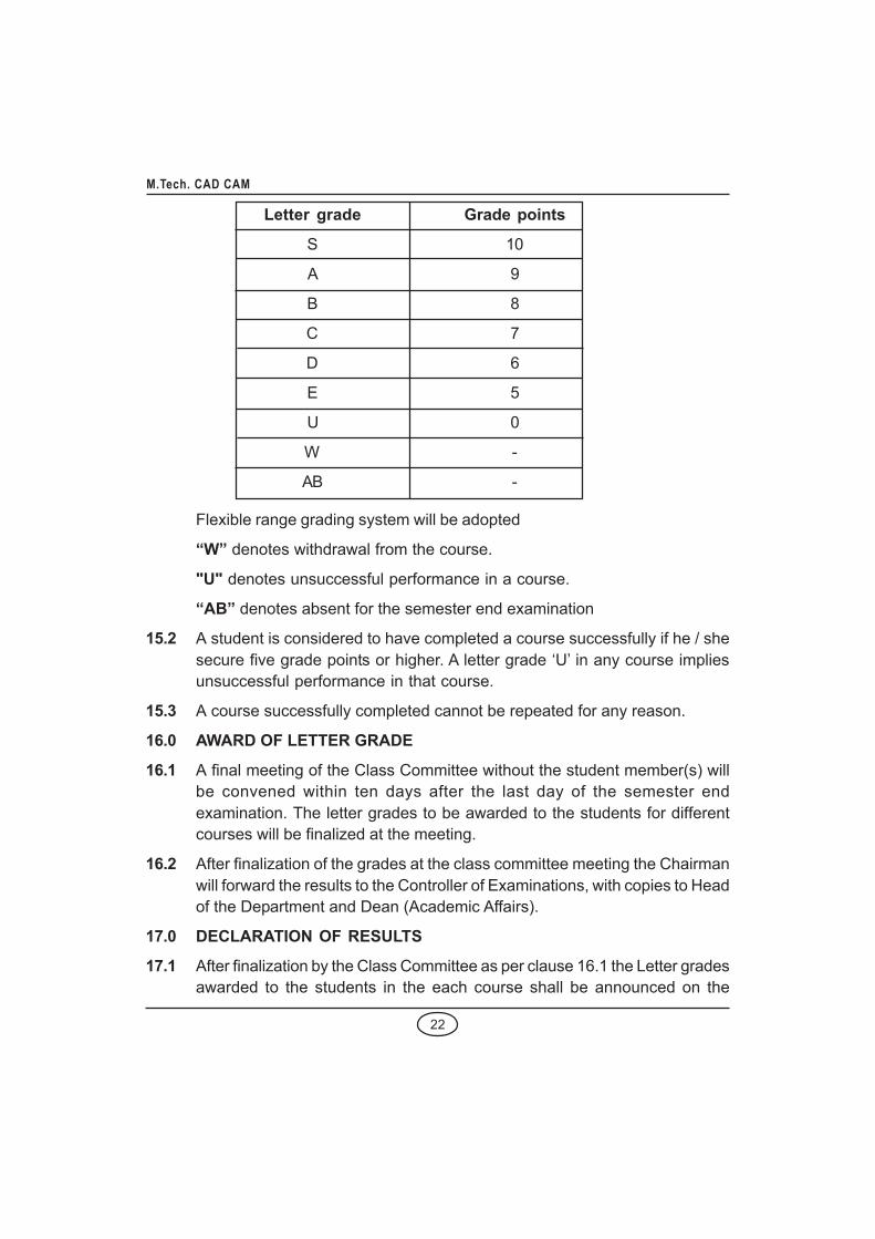
15.1 Based on the semester performance, each student is awarded a final lettergrade at the end of the semester in each course. The letter grades and thecorresponding grade points are as follows, but grading has to be relativegrading
22
M.Tech. CAD CAM
Letter grade Grade points
S 10
A 9
B 8
C 7
D 6
E 5
U 0
W -
AB -
Flexible range grading system will be adopted
“W” denotes withdrawal from the course.
"U" denotes unsuccessful performance in a course.
“AB” denotes absent for the semester end examination
15.2 A student is considered to have completed a course successfully if he / shesecure five grade points or higher. A letter grade ‘U’ in any course impliesunsuccessful performance in that course.
15.3 A course successfully completed cannot be repeated for any reason.
16.0 AWARD OF LETTER GRADE
16.1 A final meeting of the Class Committee without the student member(s) willbe convened within ten days after the last day of the semester endexamination. The letter grades to be awarded to the students for differentcourses will be finalized at the meeting.
16.2 After finalization of the grades at the class committee meeting the Chairmanwill forward the results to the Controller of Examinations, with copies to Headof the Department and Dean (Academic Affairs).
17.0 DECLARATION OF RESULTS
17.1 After finalization by the Class Committee as per clause 16.1 the Letter gradesawarded to the students in the each course shall be announced on the

23
M.Tech. CAD CAM
departmental notice board after duly approved by the Controller ofExaminations.
17.2 In case any student feels aggrieved about the results, he/she can apply forrevaluation after paying the prescribed fee for the purpose, within one weekfrom the announcement of results.
A committee will be constituted by the concerned Head of the Departmentcomprising of the Chairperson of the concerned Class Committee(Convener), the teacher concerned and a teacher of the department who isknowledgeable in the concerned course. If the Committee finds that the caseis genuine, it may jointly revalue the answer script and forward the revisedmarks to the Controller of Examinations with full justification for the revision,if any.
17.3 The “U” and “AB” grade once awarded stays in the grade sheet of the studentsand is not deleted when he/she completes the course successfully later.The grade acquired by the student later will be indicated in the grade sheet ofthe appropriate semester.
18.0 COURSE REPETITION AND ARREARS EXAMINATION
18.1 A student should register to re-do a core course wherein "W" grade is awarded.If the student is awarded "W" grade in an elective course either the sameelective course may be repeated or a new elective course may be taken.
18.2 A student who is awarded “U” or “AB” grade in a course shall write thesemester-end examination as arrear examination, at the end of the nextsemester, along with the regular examinations of next semester courses.
18.3 A student who is awarded “U” or “AB” grade in a course will have the option ofeither to write semester end arrear examination at the end of the subsequentsemesters, or to redo the course whenever the course is offered. Marksearned during the redo period in the continuous assessment for the course,will be used for grading along with the marks earned in the end-semester(re-do) examination.
18.4 If any student obtained “U” or “AB” grade, the marks earned during the redoperiod for the continuous assessment for that course will be considered forfurther appearance as arrears.
18.5 If a student with “U” or “AB” grade prefers to redo any particular course failsto earn the minimum 75% attendance while doing that course, then he/she

24
M.Tech. CAD CAM
will not be permitted to write the semester end examination and his / herearlier ‘U’ grade and continuous assessment marks shall continue.
19.0 GRADE SHEET
19.1 The grade sheet issued at the end of the semester to each student will containthe following:
(i) the credits for each course registered for that semester.
(ii) the performance in each course by the letter grade obtained.
(iii) the total credits earned in that semester.
(iv) the Grade Point Average (GPA) of all the courses registered for thatsemester and the Cumulative Grade Point Average (CGPA) of all thecourses taken up to that semester.
19.2 The GPA will be calculated according to the formula
courses of number = n Where C
)GPi)(C(GPA
ni i
ni i
∑ =
∑ ==1
1
where Ci is the number of credits assigned for ith course GPi - Grade pointobtained in the ith course For the cumulative grade point average (CGPA) asimilar formula is used except that the sum is over all the courses taken in allthe semesters completed up to the point of time.
‘W’ grade will be excluded for GPA calculations.
‘U’, ‘AB’ and ‘W’ grades will be excluded for CGPA calculations.
19.3 Classification of the award of degree will be as follows:
CGPA Classification
8.50 and above, having completed allcourses in first appearance First class with Distinction
6.50 and above, having completed withina period of 2 semesters beyond theprogramme period First Class
All others Second Class

25
M.Tech. CAD CAM
However, to be eligible for First Class with Distinction, a student should nothave obtained U grade in any course during his/her study and should havecompleted the PG Programme within a minimum period covered by theminimum duration (clause 3.1) plus authorized break of study, if any (clause8). To be eligible for First Class, a student should have passed the examinationin all courses within the specified minimum number of semesters reckonedfrom his/her commencement of study plus two semesters. For this purpose,the authorized break of study will not be counted. The students who do notsatisfy the above two conditions will be classified as second class. For thepurpose of classification, the CGPA will be rounded to two decimal places.For the purpose of comparison of performance of students and ranking, CGPAwill be considered up to three decimal places.
20.0 ELIGIBILITY FOR THE AWARD OF THE MASTERS DEGREE
20.1 A student shall be declared to be eligible for the award of the Masters Degree,if he/she has:
i) successfully acquired the required credits as specified in the Curriculumcorresponding to his/her programme within the stipulated time,
ii) no disciplinary action is pending against him/her
20.2 The award of the degree must be approved by the University.
21.0 POWER TO MODIFY
Notwithstanding all that have been stated above, the Academic Council hasthe right to modify any of the above regulations from time to time.

26
M.Tech. CAD CAM
CURRICULUM & SYLLABI FORM.TECH. (COMPUTER AIDED DESIGN)
(FOUR SEMESTERS / FULL TIME)CURRICULUMSEMESTER I
Sl. Course Course Title L T P CNo. Code1. MAB6183 Applied Mathematical Methods 3 1 0 4
2. MEB6101 Research Methodology 3 0 0 3
3. MEB6102 Applied Materials Engineering 3 0 0 3
4. MEB6103 Computer Graphics and Geometric Modeling 3 0 0 3
5. MEB6104 Finite Element Method 3 1 0 46. Elective I 3 0 0 3
7. MEB6105 CAD Laboratory 0 0 4 2
8. MEB6106 Seminar 0 0 2 1
23
SEMESTER IISl. Course Course Title L T P CNo. Code1. MEB6211 Advanced Metrology and NDT 3 0 0 3
2. MEB6212 Integrated Product Design 3 0 0 33. MEB6213 Mechanical Vibrations 3 0 0 3
4. MEB6214 Integrated Manufacturing Systems andManagement 3 0 0 3
5. Elective II 3 0 0 36. Elective III 3 0 0 3
7. MEB6215 CAM & Metrology lab 0 0 4 2
8. MEB6216 Design / Fabrication Project 0 0 4 2
22

27
M.Tech. CAD CAM
SEMESTER IIISl. Course Course Title L T P CNo. Code1. Elective IV 3 0 0 3
2. Elective V 3 0 0 3
3. Elective VI 3 0 0 3
4. MEB7102 Project Management 3 0 0 3
5. MEB7101 Project Work - Phase I 0 0 12 6*
12
SEMESTER IVSl. Course Course Title L T P CNo. Code1. MEB7101 Project Work - Phase II 0 0 3618*
Total 18 + 6 = 24 TOTAL CREDITS : 81
* Credits for Project Work Phase I to be accounted along with Project WorkPhase II in IV Semester

28
M.Tech. CAD CAM
LIST OF ELECTIVESSl. Course Course TitleNo. Code1. MEBY01 Advanced Mechanisms Design and Simulation
2. MEBY02 Advanced Strength of Materials
3. MEBY03 Advanced Tool Design
4. MEBY04 Advances in manufacturing technology
5. MEBY05 Artificial Intelligence
6. MEBY06 CNC machines and Computer Aided manufacturing
7. MEBY07 Computational Fluid Dynamics
8. MEBY08 Computer Aided Process Planning
9. MEBY09 Data Communication in CAD/CAM
10. MEBY10 Design of Hydraulic & Pneumatic Systems
11. MEBY11 Design of Material Handling Equipments
12. MEBY12 Flexible Competitive Manufacturing Systems
13. MEBY13 Industrial Robotics & Flexible Automation
14. MEBY14 Industrial Safety Management
15. MEBY15 Manufacturing Information Systems
16. MEBY16 Mechatronics
17. MEBY17 Newer Materials
18. MEBY18 Optimization Techniques in Design
19. MEBY19 Precision Engineering & Nano Technology
20. MEBY20 Rapid Prototyping and Tooling
21. MEBY21 Reliability and Total productive Maintenance
22. MEBY22 Tribology
23. SSB7181 Society, Technology & Sustainability

29
M.Tech. CAD CAM
SEMESTER I
MAB6183 APPLIED MATHEMATICAL METHODS L T P C3 1 0 4
OBJECTIVES:
• To familiarize students with boundary value problems of partial differentialequations in engineering.
• To expose the students to variational formulation and numerical integrationtechniques.
MODULE I ONE DIMENSIONAL WAVE AND HEAT EQUATIONS 8
Laplace transform methods for one-dimensional wave equation –Displacements in a line string – longitudinal vibration of an elastic bar – Fouriertransform methods for one-dimensional heat conduction problems in infiniteand semi-infinite rods.
MODULE II ELLIPTIC EQUATION 8
Laplace equation – Properties of harmonic functions – Solution of Laplace’sequation by means of Fourier transforms in a half plane, in an infinite strip andin a semi-infinite strip - Solution of Poisson equation by Fourier transformmethod.
MODULE III CALCULUS OF VARIATIONS 8
Variation and its properties – Euler’s equation – Functional dependant on firstand higher order derivatives – Functional dependant on functions of severalindependent variables – Variational problems with moving boundaries –Isoperimetric Problems – Direct methods – Ritz and Kantorovich methods.
MODULE IV NUMERICAL SOLUTION OF PARTIAL DIFFERENTIALEQUATIONS 8
Solution of Laplace's and Poisson equation on a rectangular region byLiebmann's method -Diffusion equation by the explicit and Crank Nicolson -Implicit methods - Stability and Convergence criterion - Solution of wave equationby explicit scheme.
MODULE V NUMERICAL INTEGRATION 5
Numerical Integration - Trapezoidal Rule, Simpson’s Rule, Newton - CotesFormula, Gauss Quadrature in one dimension and two dimensions.
30
M.Tech. CAD CAM
MODULE VI CONFORMAL MAPPING AND APPLICATIONS 8
The Schwarz – Christoffel transformation – Transformation of boundaries inparametric form – Physical applications – Fluid flow and heat flow Problems.
Total Hours: 60
REFERENCES:
1. Sneddon, I.N., “Elements of Partial Differential Equations”, Mc Graw-Hill, 1986.
2. Gupta, A.S., “Calculus of Variations with Applications”, Prentice Hall of IndiaPvt. Ltd, New Delhi (1997)
3. Kreyszig, E., “Advanced Engineering Mathematics”, 8th Edition, John Wiley& Sons, Inc., Singapore (2002).
4. Rogers, D.F. and Adams, J, “Mathematical Elements for Computer Graphics”,2nd Edition, Tata McGraw Hill Pub. Co. Ltd, New Delhi (2003).
5. Churchill, R.V., “Operational Mathematics”, McGraw Hill Kogakusha Ltd, Tokyo,1981.
6. L.E. Elsgolts, “Differential equations and calculus of variations”, UniversityPress of the Pacific, 2003.
OUTCOMES:
At the end of the course students will be able to
• Solve engineering problems using the concepts of Laplace transform, Fouriertransform, Calculus of Variation and Conformal mapping.
• Solve heat and flow problems of one and two dimensional conditions usingnumerical methods.

31
M.Tech. CAD CAM
MEB6101 RESEARCH METHODOLOGY L T P C3 0 0 3
OBJECTIVE:
• To provide a perspective on research to the scholars so as to broaden theirconceptions of what research involves.
• To impart knowledge on techniques related to research such as problemformulation, literature survey, information retrieval, use of statistical techniques,writing of research reports and evaluation
• To expose the scholars ethics in research and Intellectual Property Rights.
MODULE I RESEARCH PROBLEM FORMULATION 7
Research – objectives – types, Research process, Solving engineeringproblems, Identification of research topic, Formulation of research problem,Literature survey and review.
MODULE II RESEARCH DESIGN 8
Research design – meaning and need – basic concepts, Different researchdesigns, Experimental design – principle – important experimental designs,Design of experimental setup, Mathematical modeling, Simulation – validationand experimentation, Dimensional analysis and similitude.
MODULE III USE OF STATISTICAL TOOLS IN RESEARCH 12
Importance of statistics in research – concept of probability – populardistributions – sample design. Hypothesis testing, ANOVA, Design ofexperiments – factorial designs – orthogonal arrays, Multivariate analysis –Curve fitting, Correlation and regression.
MODULE IV ANALYSIS AND INTERPRETATION OF DATA 10
Research Data analysis – interpretation of results – correlation with scientificfacts, Accuracy and precision – error analysis, limitations, Use of optimizationtechniques – traditional methods – evolutionary optimization techniques.
MODULE V THE RESEARCH REPORT 8
Purpose of written report – audience, synopsis writing, preparing papers forInternational journals, Thesis writing – organization of contents – style of writing

32
M.Tech. CAD CAM
– graphs and charts – referencing, Oral presentation and defence, Ethics inresearch, Patenting, Intellectual Property Rights.
Total Hours: 45
REFERENCES:
1. Ganesan R., Research Methodology for Engineers, MJP Publishers, Chennai,2011.
2. Ernest O., Doebelin, Engineering Experimentation: planning, execution,reporting, McGraw Hill International edition, 1995.
3. George E. Dieter., Engineering Design, McGraw Hill – International edition,2000.
4. Madhav S. Phadke, Quality Engineering using Robust Design, Printice Hall,Englewood Cliffs, New Jersey, 1989.
5. Kothari C.R., Research Methodology – Methods and Techniques, New AgeInternational (P) Ltd, New Delhi, 2003.
6. Kalyanmoy Deb., “Genetic Algorithms for optimization”, KanGAL report,No.2001002.
7. Holeman, J.P., Experimental methods for Engineers, Tata McGraw HillPublishing Co., Ltd., New Delhi, 2007.
8. Govt. of India, Intellectual Property Laws; Acts, Rules & Regulations, UniversalLaw Publishing Co. Pvt. Ltd., New Delhi 2010.
9. University of New South Wales, “How to write a Ph.D. Thesis” Sydney,Australia, Science @ Unsw.
10. Shannon. R.E., System Simulation: the art and science, Printice Hall Inc,Englewood Cliffs, N.J.1995.
11. Scheffer. R.L. and James T. Mc Clave, Probability and Statistics for Engineers,PWS – Kent Publishers Co., Boston, USA, 1990.

33
M.Tech. CAD CAM
OUTCOMES:
• Students will be able to acquire a perspective on research concepts.
• Students will be able to know the techniques related to research such asproblem formulation, literature survey, information retrieval, use of statisticaltechniques, writing of research reports and evaluation
• Students will be exposed to the ethics in research and Intellectual Propertyrights

34
M.Tech. CAD CAM
MEB6102 APPLIED MATERIALS ENGINEERING L T P C3 0 0 3
OBJECTIVES:
• To study the elastic, plastic and fracture behavior of engineering materials.
• To study the various modern materials, properties and their applications.
• To understand the selection of metallic and non-metallic materials for variousengineering applications.
MODULE I ELASTIC AND PLASTIC BEHAVIOUR 12
Elasticity in metals and polymers - Mechanism of plastic deformation, role ofdislocations, yield stress, shear strength of perfect and real crystals -Strengthening mechanisms, work hardening, solid solutioning, grain boundarystrengthening, poly phase mixture, precipitation, particle, fibre and dispersionstrengthening. Effect of temperature, strain and strain rate on plastic behaviors-Super plasticity - Deformation of non crystalline material.
MODULE II FRACTURE BEHAVIOUR 15
Griffith's theory, stress intensity factor and fracture toughness - Tougheningmechanisms - Ductile, brittle transition in steel - High temperature fracture,creep - Larson-Miller parameter – Deformation and fracture mechanism maps- Fatigue, low and high cycle fatigue test, crack initiation and propagationmechanisms and Paris law - Effect of surface and metallurgical parameterson fatigue - Fracture of non metallic materials – Failure analysis, sources offailure, procedure of failure analysis.
MODULE III SELECTION OF MATERIALS 8
Motivation for selection, cost basis and service requirements - Selection formechanical properties, strength, toughness, fatigue and creep - Selection forsurface durability corrosion and wear resistance – Relationship betweenmaterials selection and processing - Case studies in materials selection withrelevance to aero, auto, marine, machinery and nuclear applications.
MODULE IV MODERN METALLIC MATERIALS 5
Dual phase steels, Micro alloyed, High strength low alloy (HSLA) steel,Transformation induced plasticity (TRIP) steel, Maraging steel - Intermetallics,

35
M.Tech. CAD CAM
Ni and Ti aluminides - Smart materials, shape memory alloys - Metallic glass- Quasi crystal and nano crystalline materials.
MODULE V NON METALLIC MATERIALS 5
Polymeric materials - Formation of polymer structure - Production techniquesof fibres, foams, adhesives and coatings - Structure, properties andapplications of engineering polymers -Advanced structural ceramics, WC, TiC,TaC, AI2O3, SiC, Si3N4, CBN and diamond - properties, processing andapplications.
Total Hours: 45
REFERENCES:
1. Thomas H.Courtney, “Mechanical Behaviour of Materials”, (2nd Edition),McGraw-Hill, 2000.
2. Charles J.A., Crane, F.A.A and Furness, J.A.G., “Selection and use ofEngineeringMaterials ", (3rd Edition), Butterworth-Heiremann, 1977.
3. Flinn, R.A. and Trojan, P.K., “Engineering Materials and their Applications”,(4th Edition),Jaico, 1999.
4. George E.Dieter, “Mechanical Metallurgy”, McGraw Hill, 1988.
5. Metals Hand Book, Vol.10, “Failure Analysis and Prevention”, (10th Edition),1994.
OUTCOMES:
• Students will be able to study the elastic, plastic and fracture behavior ofengineering materials.
• Students will be able to study the various modern materials , properties andtheir applications.
• Students will be able to understand the selection of metallic and non-metallicmaterials for various engineering applications.

36
M.Tech. CAD CAM
MEB6103 COMPUTER GRAPHICS AND GEOMETRIC L T P CMODELLING 3 0 0 3
OBJECTIVES:
• To acquire knowledge for generating high quality images of massive geometricmodels in a short time.
• To learn about the concepts of surface modeling, physically based modelingand surface visualization.
MODULE I IMAGE GENERATION AND MANIPULATION 9
Overview of display devices and systems – generation of primitives – 2D &3D transformation –viewing transformation – projections.
MODULE II IMAGE ENHANCEMENT AND GRAPHICS STANDARDS 9
Clipping – Hidden line/surface removal – shading and rendering; Graphicstandards – Computing shades – Data exchange standards – DataCommunication Standards.
MODULE III MODELLING OF CURVES AND SURFACES 9
Curves: Parametric representation – Analytic curves; synthetic curves –Bicubic, Bezier, B-spline, NURBS; Surfaces: surface patches – Bicubic – Bezier– B-spline – Coons patch, Sweep surfaces; continuity conditions; manipulationof curves & surfaces.
MODULE IV MODELLING OF SOLIDS 9
Constructive Solid Geometry (CSG) – Boundary Models – Sweeping; Othermethods of solid modeling; Constraint based modeling – parametric –variational; Feature based modeling; Data associativity; features of Solidmodeling packages – current trends in modeling.
MODULE V GRAPHICS IN DESIGN AND MANUFACTURE 9
Graphical techniques in FEA: preprocessing – mesh generation techniques –error detection; Post processing – display of results – animated shapes;Graphical techniques in manufacture –estimation of material removal quantity– cutter and gauge detection – tool path generation; Rapid prototype – slicingtechniques.
Total Hours: 45

37
M.Tech. CAD CAM
REFERENCES:
1. Ibrahim Zeid, CAD / CAM- Theory and Practice, Mc Graw Hill InternationalEdition, 1998.
2. Chris Mc Mahon and Jimmie Browne, CAD CAM – Principles, Practice andManufacturing Management, 2nd edition, Pearson Education Asia LN, 2005.
3. Donald Hearn and Pauline Baker, Computer Graphics Printice Hall Inc.
OUTCOMES:
• Students would acquire knowledge for generating high quality images ofmassive geometric models in a short time.
• Students would learn about the concepts of surface modeling, physicallybased modeling and surface visualization.

38
M.Tech. CAD CAM
MEB6104 FINITE ELEMENT METHOD L T P C3 1 0 4
OBJECTIVES:
• To study the fundamentals of finite element method.
• To apply finite element method for solving one dimensional and twodimensional structural and thermal problems.
• To apply finite element method for non linear and structural dynamic problem.
MODULE I REVIEW OF ONE DIMENSIONAL FEM 9
FEM Methodology – Modeling and discretization Interpolation, elements, nodesand degrees-of-freedom-applications of FEA. One-Dimensional Elements: Barelement – beam element – assembly of elements – properties of stiffnessmatrices-boundary conditions-solution of equations-mechanical loads andstresses-thermal loads and stresses-example problems.
MODULE II REVIEW OF TWO AND THREE DIMENSIONAL FEM 9
Interpolation and shape functions - element matrices-linear triangular elements(CST)-quadratic triangular elements – bilinear rectangular elements- solidelements-higher order elements – stress calculations.
MODULE III APPLICATIONS TO FIELD PROBLEMS 9
Solution to problems in linear elasticity- plane problems in elasticity- platesand shells- solution of problems in heat-transfer and fluid mechanics- numericalexamples- discussion on error estimates.
MODULE IV NON-LINEAR ANALYSIS 9
Non-linear problems in elasticity- some solution methods- plasticity:introduction, general formulation for small strains- formulation for von Misestheory- computational procedure- geometric non-linearity- modelingconsiderations.
MODULE V FINITE ELEMENTS IN STRUCTURAL DYNAMICSAPPLICATIONS 9
Dynamic equations – mass and damping matrices – natural frequencies andmodes – damping – reduction of number of degrees-of-freedom-response

39
M.Tech. CAD CAM
history – model methods – Ritz vectors – component mode synthesis –harmonic response – direct integration techniques – explicit and implicitmethods – analysis by response spectra – example problems.
Total Hours: 60
REFERENCES:
1. Reddy J.N. An Introduction to the Finite Element Method, McGraw Hill,International Edition, 1993.
2. Cook, Robert Davis et al “Concepts and Applications of Finite ElementAnalysis”, Wiley, John & Sons, 1999.
3. Chandrupatla & Belagundu, “Finite Elements in Engineering”, Prentice Hallof India Private Ltd., 1997.
4. Zienkiewicz.O.C, Taylor.R.L “The Finite Element Method” McGraw HillInternational Editions, Fourth Edition, 1991, Volume 2.
5. Bathe, K.J., “Finite Element Procedures in Engineering Analysis, 1990.
6. S.S.Rao, Finite Element Analysis, 2002 Edition.
7. David V Hutton “Fundamentals of Finite Element Analysis”. McGraw-HillInternational Edition, 2004.
OUTCOMES:
• Students can study the fundamentals of finite element method.
• Students can apply finite element method for solving one dimensional andtwo dimensional structural and thermal problems.
• Students can apply finite element method fir nonlinear and structural dynamicproblems.

40
M.Tech. CAD CAM
MEB6105 CAD LABORATORY L T P C0 0 4 2
OBJECTIVES:
• To review and train in CAD modeling.
• To train on various areas of finite element analysis of mechanical components.
LIST OF EXERCISES
1. Review of Computer Aided Drafting, Solid Modeling assembly and drawinggeneration using a CAD Package.
2. Analysis of Mechanical Components – Use of FEA packages, Exercises shallinclude FEA analysis of
i) Machine elements under static loads
ii) Heat transfer and Flow Analysis
iii) Determination of natural frequency
iv) Non-linear Analysis
v) Contact Analysis
vi) Fatigue Analysis
3. Use of kinematics and dynamics simulation software - Analysis of velocity &acceleration for mechanical linkages of different mechanisms.
OUTCOMES:
• Students will be able to review and train in CAD modeling.
• Students will be get trained on various areas of finite element analysis ofmechanical components.

41
M.Tech. CAD CAM
SEMESTER IIMEB6211 ADVANCED METROLOGY AND NDT L T P C
3 0 0 3
OBJECTIVE:
• To gain knowledge in the advanced measuring methods and the nondestructive techniques.
MODULE I MEASURING MACHINES 9
Tool Maker's microscope - Co-ordinate measuring machines - Universalmeasuring machine - Laser metrology - Use of computers - Machine visiontechnology -Microprocessors in metrology.
MODULE II STATISTICAL QUALITY CONTROL 9
Data presentation - Statistical measures and tools - Process capability – controlcharts for variables and for attributes - Theory of probability – Sampling plants- Reliability and life testing.
MODULE III LIQUID PENETRANT AND MAGNETIC PARTICLE TESTS 9
Characteristics of liquid penetrates - different washable systems - Developers- applications - Methods of production of magnetic fields - Principles of operationof magnetic particle test - Applications - Advantages and limitations.
MODULE IV RADIOGRAPHY 9
Sources of ray-x-ray production - properties of Gamma and x rays - filmcharacteristics - exposure charts - contrasts - operational characteristics of xray equipment - applications.
MODULE V ULTRASONIC AND ACOUSTIC EMISSION TECHNIQUES 9
Production of ultrasonic waves - different types of waves - generalcharacteristics of waves - pulse echo method - A, B, C scans - Principles ofacoustic emission techniques - Advantages and limitations - Instrumentationand applications.
Total Hours: 45

42
M.Tech. CAD CAM
REFERENCES:
1. JAIN, R.K. “Engineering Metrology", Khanna Publishers, 1997.
2. Barry Hull and Vernon John, " Non Destructive Testing ", MacMillan, 1988.
3. American Society for Metals, “Metals Hand Book", Vol. II, 1976.
4. Progress in Acoustic Emission, “Proceedings of 10th International AcousticEmission Symposium", Japanese Society for NDI, 1990.
OUTCOME:
• Students would gain knowledge in the advanced measuring methods andthe non destructive techniques.

43
M.Tech. CAD CAM
MEB6212 INTEGRATED PRODUCT DESIGN L T P C3 0 0 3
OBJECTIVE:
• To gain knowledge on multiple functional areas like marketing, finance,industrial design, engineering and production in creating a new product
MODULE I INTRODUCTION 8
Need for IPPD-Strategic importance of Product development - integration ofcustomer, designer, material supplier and process planner, Competitor andcustomer - behavior analysis. Understanding customer-promoting customerunderstanding-involve customer in development and managing requirements- Organization process management and improvement.
MODULE II CONCEPT GENERATION, SELECTION AND TESTING 10
Plan and establish product specifications. Task - Structured approaches -clarification - search-externally and internally-Explore systematically - reflecton the solutions and processes - concept selection - methodology - benefits.Implications - Product change - variety - component standardization - productperformance - manufacturability – Concept Testing Methodologies.
MODULE III PRODUCT ARCHITECTURE 8
Product development management - establishing the architecture - creation -clustering - geometric layout development - Fundamental and incidentalinteractions - related system level design issues - secondary systems -architecture of the chunks - creating detailed interface specifications-PortfolioArchitecture.
MODULE IV INDUSTRIAL DESIGN 8
Integrate process design - Managing costs - Robust design - Integrating CAE,CAD, CAM tools – Simulating product performance and manufacturingprocesses electronically - Need for industrial design-impact – design process- investigation of customer needs - conceptualization - refinement -management of the industrial design process - technology driven products -user - driven products - assessing the quality of industrial design.

44
M.Tech. CAD CAM
MODULE V DESIGN FOR MANUFACTURING AND PRODUCTDEVELOPMENT 11
Definition - Estimation of Manufacturing cost-reducing the component costsand assembly costs – Minimize system complexity - Prototype basics -Principles of prototyping - Planning for prototypes - Economic Analysis -Understanding and representing tasks-baseline project planning - acceleratingthe project-project execution.
Total Hours: 60
REFERENCES:
1. Karl T.Ulrich and Steven D.Eppinger, Product Design and Development,McGraw Hill International Edns.1999
2. Concurrent Engg./Integrated Product Development. Kemnneth Crow, DRM
3. Associates, 6/3,Via Olivera, Palos Verdes, CA 90274(310) 377-569,Workshop Book
4. Effective Product Design and Development, Stephen Rosenthal, BusinessOne Orwin, Homewood, 1992,ISBN, 1-55623-603-4
5. Tool Design – Integrated Methods for successful Product Engineering, StuartPugh, Addison Wesley Publishing,Neyourk, NY, 1991, ISBN 0-202-41639-5
OUTCOME:
• Students would gain knowledge on multiple functional areas like marketing,finance, industrial design, engineering and production in creating a newproduct.

45
M.Tech. CAD CAM
MEB6213 MECHANICAL VIBRATIONS L T P C3 0 0 3
OBJECTIVES:
• To understand the fundamentals of vibration phenomenon and itsmeasurement.
• To know the various constraints of vibration system and its analysis.
• To study the vibrations of various generic components, its effect on balancingand the devices for its measurements.
MODULE I FUNDAMENTALS OF VIBRATION 8
Review of Single degree system - Response to arbitrary periodic exicitations- Duhamel's Integral – Impulse Response function - Virtual work - Lagrange'sequation - Single degree freedom forced vibration with elastically coupledviscous dampers - System Identification from frequency response - TransientVibration – Laplace transformation formulation.
MODULE II TWO - DEGREE FREEDOM SYSTEMS 8
Free vibration of spring - coupled system - mass coupled system - Bendingvibration of two degree of freedom system - forced vibration - Vibration Absorber- Vibration isolation.
MODULE III MULTI-DEGREE FREEDOM SYSTEM 12
Normal mode of vibration - Flexibility Matrix and Stiffness matrix - Eigen valuesand Eigen vectors – orthogonal properties - Modal matrix-Modal Analysis -Forced Vibration by matrix inversion - Modal damping in forced vibration -Numerical methods for fundamental frequencies
MODULE IV VIBRATION OF CONTINUOUS SYSTEMS 8
Systems governed by wave equations - Vibration of strings - vibration of rods- Euler Equation for Beams -Effect of Rotary inertia and shear deformation -Vibration of plates.
MODULE V MACHINE DYNAMICS 9
Vibration isolation – Role of foundation – Balancing of rotating and reciprocatingmasses in machines – Applications in machines like Turbines, Compressors,Grinding Machine and Presses.

46
M.Tech. CAD CAM
Experimental Vibration Analysis - Vibration exciters, Sensors and SpectrumAnalysers - Industrial case studies.
Total Hours: 45
REFERENCES:
1. Thomson, W.T. - "Theory of Vibration with Applications", CBS Publishersand Distributors, NewDelhi, 1990.
2. Rao, J.S., & Gupta, K. - "Introductory Course on Theory and Practice ofMechanical Vibrations", New Age International Ltd., 1984.
3. Den Hartog, J.P. "Mechanical Vibrations", Dover Publication 1990.
4. Rao, S.S., "Mechanical Vibrations", Addison Wesley Longman 1995.
OUTCOMES:
• Students can be able to understand the fundamentals of vibration phenomenonand its measurement.
• Students can be able to know the various constraints of vibration system andits analysis.
• Students can be able to study the vibrations of various generic components,its effect on balancing and the devices for its measurements.

47
M.Tech. CAD CAM
MEB6214 INTEGRATED MANUFACTURING SYSTEMS AND L T P CMANAGEMENT 3 0 0 3
OBJECTIVES:
• To know about the Product life cycle and its management.
• To learn the Manufacturing strategies and compositeness.
• To understand the Designing of Products, facilities and jobs.
• To gain knowledge on Inventory systems, MRP and information controlsystems.
MODULE I FIELD OF MANUFACTURING MANAGEMENT 9
Introduction – Manufacturing Strategies and competitiveness-Meeting thecompetitive Project management-Product Life Cycle – Role of CIM in ModernManufacturing Management.
MODULE II DESIGNING OF PRODUCTION PROCESSES 9
Process selection-Process flow Design – Operations Technology -Waitingline management-Computer simulation of waiting lines – Quality management.
MODULE III DESIGN OF FACILITIES AND JOBS 9
Capacity and Requirement planning – Strategies – Planning service capacity-JIT –Facility location and layout-Job Design and Work measurement. – LeanManufacturing.
MODULE IV INVENTORY SYSTEMS AND MRP 9
Definition-Purposes of Inventory-Inventory models-Fixed order Quantity modelsand Fixed-time period models - MRP Systems-MRP system structures-Improvements in the MRP system-Advanced MRP-type systems.
MODULE V INFORMATION SYSTEM FOR MANUFACTURING 9
Parts oriented production information system - concepts and structure -computerized production scheduling, online production control systems,Computer based production management system, computerizedmanufacturing information system - case study.
Total Hours: 45

48
M.Tech. CAD CAM
REFERENCES:
1. Chase, Aquilano and Jacobs, Production and Operations Management, , TataMcGraw Hill, eighth Edition.
2. Robert A. Olsen, Manufacturing management: a quantitativeapproach,International Textbook Co, 1968.
3. Chary S.N., Production and Operations Management, Tata McGraw-Hill, 3rdEdition 2006.
4. Jay Heizer, Barry Render Production and Operations Management: Strategicand Tactical Decisions, Business & Economics – 1996.
5. Jae K. Shim, Joel G. Siegel, Operations Management,- Business & Economics– 1999.
OUTCOMES:
• Students would know about the Product life cycle and its management.
• Students would learn the Manufacturing strategies and compositeness.
• Students would understand the Designing of Products, facilities and jobs.
• Students would gain knowledge on Inventory systems, MRP and informationcontrol systems.

49
M.Tech. CAD CAM
MEB6215 CAM & METROLOGY LAB L T P C0 0 4 2
OBJECTIVES:
• To train on part programming and program generation from a CAD model.
• To train on machining in various CNC machines.
• To train on various modern measuring instruments.
LIST OF EXERCISES :
1. Computer Aided Manufacturing
(i) Automatic Program Generation for CNC Machining using advanced CAMPackages
(ii) Machining of components in VMC and Turning Center using programsgenerated by CAM packages
(iii) Machining using special machining cycles in Fanuc and Siemenscontrollers
2. Metrology
(i) Measurement of dimensional features in complex components like engineblock or cylinder head using CMM
(ii) Cloud point data generation for Free form surfaces using CMM
(iii) Automated inspection using Vision system
(iv) Surface roughness measurement
(v) Comprehensive reverse engineering of industrial components
OUTCOMES:
• Students would get trained on part programming and program generationfrom a CAD model
• Students would get trained on machining in various CNC machines
• Students would get trained on various modern measuring instruments

50
M.Tech. CAD CAM
MEB6216 DESIGN / FABRICATION PROJECT L T P C0 0 4 2
The main objective is to inculcate problem based learning and to promoteteam spirit.
Students will be asked to take a real world problem and solve it by designing orfabricating a system
The students will work in groups.

51
M.Tech. CAD CAM
SEMESTER IIIMEB7102 PROJECT MANAGEMENT L T P C
3 0 0 3
OBJECTIVES:
• To acquire knowledge on project planning, implementation and analysis.
• To give an exposure on network analysis and Project scheduling.
MODULE I INTRODUCTION & PROJECT INITIATION 9
Introduction to PM: Projects in Contemporary Organization, Project Life CycleProject Initiation: Strategic Management, Project Selection & Evaluation,Selection Criteria & Models.
MODULE II RISK ANALYSIS 9
Risk Management, Portfolio Process, Project Proposals, Project manager:Demands on Project manager, Selecting the Project Manager, MulticulturalCommunication, Project Organization: Organizational Concepts in PM,Selecting an Organizational Form.
MODULE III PROJECT PLANNING & IMPLEMENTATION 9
Project Planning: Systems integration, WBS, Responsibility Charts, InterfaceCoordination, Conflict and Negotiation in PM: Nature of Negotiation, Conflictand Project Life Cycle.
Project Implementation: Budgeting and Cost Estimation: Estimating ProjectBudgets, Improving Cost.
MODULE IV NETWORK ANALYSIS & PROBLEMS 9
Algorithms for shortest route problems-Dijkstra's, Flyod's, and Dantzig'salgorithms; Algorithms for minimal spanning tree- Kruskal's algorithm andPrim's algorithm; Algorithms for maximal flow problems. Maximum flowminimum cut explanation.
Estimation Process, Scheduling: Background, Network Techniques: PERT &CPM, Risk Analysis.

52
M.Tech. CAD CAM
MODULE V PROJECT SCHEDULING WITH LIMITED RESOURCES 9
Complexity of project scheduling with limited resources, leveling the demandson key resources, A simple heuristic program for resource allocation.
REFERENCES:
1. A Management Guide to PERT/CPM, Jerome, D. Weist and Ferdinand K.Levy, Prentice Hall of India, New Delhi, 1994.
2. Projects Planning, Implementation and Control, Prasanna Chandra, TataMcGraw-Hill, Publishing Company Ltd., New Delhi, 1995.
3. Operations Research: Principles and Practice, Ravindran, A. Phillips, Don T.and Solberg, James J. Second edition, John Wiley & Sons, 1987.
4. Project Management with CPM and PERT, Moder J.V. and Phillips, C.R.E.Van Nostrand Reinhold Company, 1964.
5. Project Management and Control, Narendra Singh, Himalaya Publishing
OUTCOME:
• On completion of the course the student will be able to plan, schedule, analyzeand execute the project effectively.
53
M.Tech. CAD CAM
ELECTIVESMEBY01 ADVANCED MECHANISMS DESIGN L T P C
AND SIMULATION 3 0 0 3
OBJECTIVE:
• To provide knowledge in the kinematic analysis of mechanisms and theirsynthesis
MODULE I INTRODUCTION 9
Review of fundamentals of kinematics-classifications of mechanisms-components of mechanisms – mobility analysis – formation of one D.O.F.multi loop kinematic chains, Network formula – Gross motion concepts-Basickinematic structures of serial and parallel robot manipulators-Compliantmechanisms-Equivalent mechanisms.
MODULE II KINEMATIC ANALYSIS 9
Position Analysis – Vector loop equations for four bar, slider crank, invertedslider crank, geared five bar and six bar linkages. Analytical methods for velocityand acceleration Analysis– four bar linkage jerk analysis. Plane complexmechanisms-auxiliary point method. Spatial RSSR mechanism-Denavit-Hartenberg Parameters – Forward and inverse kinematics of robotmanipulators.
MODULE III PATH CURVATURE THEORY, COUPLER CURVE 9
Fixed and moving centrodes, inflection points and inflection circle. Euler Savaryequation, graphical constructions – cubic of stationary curvature. Four barcoupler curve-cusp-crunode-coupler driven six-bar mechanisms-straight linemechanisms.
MODULE IV SYNTHESIS OF FOUR BAR MECHANISMS 9
Type synthesis – Number synthesis – Associated Linkage Concept.Dimensional synthesis – function generation, path generation, motiongeneration. Graphical methods-Pole technique-inversion technique-pointposition reduction-two, three and four position synthesis of four- barmechanisms. Analytical methods- Freudenstein’s Equation-Bloch’s Synthesis.

54
M.Tech. CAD CAM
MODULE V SYNTHESIS OF COUPLER CURVE BASED MECHANISMS &CAM MECHANISMS 9
Cognate Lingages-parallel motion Linkages. Design of six bar mechanisms-single dwell-double dwell-double stroke. Geared five bar mechanism-multi-dwell. Cam Mechanisms- determination of optimum size of cams. Mechanismdefects. Study and use of Mechanism using Simulation Soft-ware packages.Students should design and fabricate a mechanism model as term project.
Total Hours: 45
REFERENCES:
1. Robert L.Norton., “Design of Machinery”,Tata McGraw Hill, 2005.
2. Sandor G.N., and Erdman A.G., “Advanced Mechanism Design Analysis andSynthesis”, Prentice Hall, 1984.
3. Uicker, J.J., Pennock, G. R. and Shigley, J.E., “Theory of Machines andMechanisms”, Oxford University Press, 2005.
4. Amitabha Ghosh and Asok Kumar Mallik, “Theory of Mechanism andMachines”, EWLP, Delhi, 1999.
5. Kenneth J, Waldron, Gary L. Kinzel, “Kinematics, Dynamics and Design ofMachinery”, John Wiley-sons, 1999.
6. Ramamurti, V., “Mechanics of Machines”, Narosa, 2005.
OUTCOME:
• Students are expected to have understood the kinematic analysis andsynthesis of four bar mechanism, coupler curve based mechanism and cammechanism.

55
M.Tech. CAD CAM
MEBY02 ADVANCED STRENGTH OF MATERIALS L T P C3 0 0 3
OBJECTIVE:
• To provide knowledge in the design of 2D and 3D members by understandingtheir state of stresses and the design of curved members and non circularsections.
MODULE I ELASTICITY 9
Stress-Strain relations and general equations of elasticity in Cartesian, Polarand curvilinear coordinates, differential equations of equilibrium-compatibility-boundary conditions-representation of three-dimensional stress of a tensiongeneralized hook's law - St. Venant's principle - plane stress - Airy's stressfunction. Energy methods.
MODULE II SHEAR CENTER AND UNSYMMETRICAL BENDING 10
Location of shear center for various thin sections - shear flows. Stresses Anddeflections in beams subjected to unsymmetrical loading-kern of a section.
MODULE III CURVED FLEXIBLE MEMBERS AND STRESSES IN FLATPLATES 10
Circumference and radial stresses – deflections - curved beam with restrainedends - closed ring subjected to concentrated load and uniform load - chainlinks and crane hooks. Solution of rectangular plates – pure bending of plates– deflection – uniformly distributed load – various end conditions.
MODULE IV TORSION OF NON-CIRCULAR SECTIONS 7
Torsion of rectangular cross section - St.Venants theory - elastic membraneanalogy - Prandtl's stress function - torsional stress in hollow thin walled Stress
MODULE V STRESSES IN ROTARY SECTIONS AND CONTACTSTRESSES 9
Radial and tangential stresses in solid disc and ring of uniform thickness andvarying thickness allowable speeds. Methods of computing contact stress-deflection of bodies in point and line contact applications.
Total Hours: 45

56
M.Tech. CAD CAM
REFERENCES:
1. Arthur P Boresi, Richard J. Schmidt, “Advanced mechanics of materials”,JohnWiley, 2002.
2. Timoshenko and Goodier, "Theory of Elasticity", McGraw Hill.
3. Robert D. Cook, Warren C. Young, "Advanced Mechanics of Materials", Mcmillan pub. Co., 1985.
4. Srinath. L.S., “Advanced Mechanics of solids”, Tata McGraw Hill, 1992.
5. Ryder G H ,Strength of Materials Macmillan, India Ltd, 2007
OUTCOME:
• The students are expected to Analyze two dimensional complex stressproblems; Calculate stress and deflections in curved beams, Analyze torsionof non circular and thin walled sections.

57
M.Tech. CAD CAM
MEBY03 ADVANCED TOOL DESIGN L T P C3 0 0 3
OBJECTIVES:
• To study the basic concepts of tool design.
• To design various tooling such as cutting tools, Jigs and fixtures, press toolsand CNC machine tools.
MODULE I TOOL-DESIGN METHODS 5
Introduction – The Design Procedure – Statement of the problem – The NeedsAnalysis –Research and Ideation – Tentative Design Solutions – The FinishedDesign – Drafting and Design Techniques in Tooling drawings – Screws andDowels – Hole location – Jig-boring practice –Installation of Drill Bushings –Punch and Die Manufacture – Electro-discharge machining –Electro-dischargemachining for cavity.
MODULE II TOOLING MATERIALS AND HEAT TREATMENT 9
Introduction – Properties of Materials – Ferrous Tooling Materials – Tool steels– Cast Iron – Mild, or low-carbon Steel – Nonmetallic Tooling Materials –Nonferrous Tooling Materials – Metal cutting Tools – Single-point cutting tools– Milling cutters – Drills and Drilling – Reamer classification –Taps – Tapclassification- the selection of carbide cutting tools – Determining the insertthickness for carbide tools.
MODULE III DESIGN OF DRILL JIGS 9
Introduction – Fixed Gages – Gage Tolerances – The selection of material forGages – Indicating Gages – Automatic gages – Principles of location – Locatingmethods and devices – Principles of clamping – Drill jigs – Chip formation indrilling – General considerations in the design of drill jigs – Drill bushings –Methods of construction – Drill jigs and modern manufacturing.
MODULE IV DESIGN OF FIXTURES AND DIES 14
Introduction – Fixtures and economics – Types of Fixtures – Vise Fixtures –Milling Fixtures –Boring Fixtures – Broaching Fixtures – Lathe Fixtures –Grinding Fixtures – Types of Die construction – Die-design fundamentals –Blanking and Piercing die construction – Pilots – Strippers and pressure pads-

58
M.Tech. CAD CAM
Presswork materials – Strip layout – Short-run tooling for Piercing – Bendingdies – Forming dies – Drawing operations.
MODULE V TOOL DESIGN FOR NUMERICALLY CONTROLLEDMACHINE TOOLS 8
Introduction – The need for numerical control – A basic explanation of numericcontrol – Numerical control systems in use today – Fixture design fornumerically controlled machine tools – Cutting tools for numerical control –Tool holding methods for numerical control – Automatic tool changers and toolpositioners – Tool presetting – Introduction – General explanation of the Brownand sharp machine – tooling for Automatic screw machines.
Total Hours: 45
REFERENCES:
1. Cyrll Donaldson, George H.LeCain, V.C. Goold, “Tool Design”, Tata McGrawHill Publishing Company Ltd., 2000.
2. Prakash Hiralal Joshi, “Tooling data”, Wheeler Publishing, 2000.
OUTCOMES:
• Students will be able to study the basic concepts of tool design.
• Students will be able to design various tooling such as cutting tools, Jigs andfixtures, press tools and CNC machine tools.

59
M.Tech. CAD CAM
MEBY04 ADVANCES IN MANUFACTURING TECHNOLOGY L T P C3 0 0 3
OBJECTIVES:
• To study the various newer machining processes and their applications.
• To understand the concepts of various micro fabrication devices andtechnology.
MODULE I METAL CUTTING AND TOOL MATERIALS 12
Orthogonal and oblique cutting - Types of tool wear, Abrasion, Diffusion,Oxidation, Fatigue and Adhesive wear - Prediction of tool life - Monitoring oftool wear, Cutting forces and vibration – Tool materials, Cemented carbide,Coated carbide, Cermets, Ceramic, CBN and PCD - Selection of machiningparameters and Tools.
MODULE II SPECIAL MACHINING 9
Deep hole drilling - Gun drills - Gun boring - Trepanning - Honing - Lapping -Super finishing - Burnishing - Broaching - High speed machining.
MODULE III UNCONVENTIONAL MACHINING 9
Principles, processes, Various influencing parameters and Applications ofUltrasonic machining, Electro Discharge Machining, Electro ChemicalMachining, Electron and Laser Beam Machining, Plasma Arc Machining andWater Jet Machining.
MODULE IV RAPID PROTOTYPING 6
Stereo lithography - Laminated object manufacturing - selective laser sintering- Vacuum process casting – Resin injection - Applications of RPT - Microfinishing process.
MODULE V ARTIFICIAL INTELLIGENCE AND EXPERT SYSTEMS 9
Introduction - Pattern recognition - Control strategies - Heuristic search,Forward and Backward reasoning - Search algorithms - Game playing -Knowledge representation - structural representation of knowledge – Expertsystems in manufacturing.
Total Hours: 45

60
M.Tech. CAD CAM
REFERENCES:
1. Armarego E.J.A. and Brown R.H., “The machining of metals ", Prentice Hall,1982.
2. Battacharya," Theory of metal cutting ", NCB Agency, 1984.
3. HMT Manual, “Non-traditional machining methods ", 1975.
4. Rich E. and Knight K., “Artificial Intelligence ", McGraw Hill Inc, 1991.
5. Pham D.T., “Expert Systems in Engineering ", IFS Publishers, Springer-Verlag,1988.
6. Durvent W.R., “The Lithographic hand book ", Narosa Publishers, 1995.
7. Pandey P.S. and Shah N. “Modern Manufacturing Processes ", 1980.
8. Sadasivan T.A. and Sarathy D. “Cutting tools for Productive Machining ", Widia(India) Limited, 1999.
OUTCOMES:
• Students will be able to know the various newer machining processes andtheir applications.
• Students will be able to understand the concepts of various micro fabricationdevices and technology.
61
M.Tech. CAD CAM
MEBY05 ARTIFICIAL INTELLIGENCE L T P C3 0 0 3
OBJECTIVE:
• To learn about the fundamentals of artificial intelligence and application tools.
• To know about the implementation of artificial intelligence in Industry and thesuspected problems.
MODULE I INTRODUCTION TO ARTIFICIAL INTELLIGENCE 9
Definition, Three AI branches- Expert Systems, Natural language systems,Perception for vision, speech and touch-Eminent domains-misconception-human intelligence- Development of an system: goal, fact obtaining data- rules,inferences- verification thro- the inference Mechanism.
MODULE II KNOWLEDGE BASED SYSTEMS 9
Identification – knowledge bases- knowledge- representation – methods-reasoning strategies frames, rules- logic, scamentic network. Object orientedprogramming- acquiring knowledge from an expert.
MODULE III AI APPLICATION DEVELOPMENT TOOLS 8
Building a knowledge system- choosing a tool for building expert system-inheritance- A knowledge base tool with data base feature application areas-problem features.
MODULE IV AI IN INDUSTRY 10
Planning and scheduling- Project management-factory simulation- Long termplanning and integration of knowledge systems. Sales, design, Manufacturing,distribution, field services and Expert system integration- Diagnosis and Troubleshooting overview of robots applications- Welding, spray painting, grinding-Pa…. handling transfer, assembly operation, parts sorting and inspection.
MODULE V PERCEPTION AND WARNING 9
Techniques used in solving, perceptual problems-constraint satisfaction,random learning and Neural nets, concept learning by analogy, Introduction toAI Programming language.
Total Hours: 45

62
M.Tech. CAD CAM
REFERENCES:
1. Winston, P.H., “Artificial Intelligence”, Addision Wesley.
2. Nilsson, N.J., “Principles of Artificial Intelligence”,
3. Rich, E., “Artificial Intelligence”, Mc Graw Hill, 1983.
4. Rauch Hindin.B., “A guide to commercial Artificial Intelligence – Fundamentalsand real world applications”, Prentice Hall, Englewood Cliffs, New Jerscy.
5. Klafter, Richard D., and Chemieleswski,A., “ Robotic Engineering”, PrenticeHall international Editions.
OUTCOMES:
• Students will be able to learn about the fundamentals of artificial intelligenceand application tools.
• Students will be able to know about the implementation of artificial intelligencein Industry and the suspected problems.

63
M.Tech. CAD CAM
MEBY06 CNC MACHINES AND COMPUTER AIDED L T P CMANUFACTURING 3 0 0 3
OBJECTIVE:
• To impart in depth knowledge of Computer Numerical Machines and variousprogramming modules involved in Computer Aided Manufacturing system.
MODULE I INTRODUCTION TO CNC MACHINE TOOLS 7
Development of CNC Technology, principles, features, advantages, economicbenefits, applications, CNC, DNC concept, classification of CNC Machine,types of control, CNC controllers, characteristics, interpolators.
MODULE II STRUCTURE OF CNC MACHINE TOOL 9
CNC Machine building, structural details, configuration and design, guideways- friction and anti friction and other types of guide ways, elements used toconvert the rotary motion to a linear motion - Screw and nut, recirculating ballscrew, planetary roller screw, recirculating roller screw, rack and pinion, torquetransmission elements - gears, timing belts, flexible couplings, Bearings.
MODULE III DRIVES AND CONTROLS 9
Spindle drives - DC shunt motor, 3 phase AC induction motor, feed drives -stepper motor, servo principle, DC & AC servomotors. Open loop and closedloop control, Axis measuring system - synchro, synchro-resolver, gratings,moire fringe gratings, encoders, inductosyn, laser interferometer.
MODULE IV CNC PROGRAMMING 10
Coordinate system, structure of a part program, G & M Codes, Manual partprogramming for Fanuc, Heidenhain, Sinumeric control system, CAPP, APTpart programming using CAD/CAM, Parametric Programming.
MODULE V TOOLING AND MAINTENANCE OF CNC 10
Cutting tool materials, carbide insets classification, qualified, semi qualifiedand preset tooling, tooling system for Machining centre and Turning centre,work holding devices, maintenance of CNC Machines.
Total Hours: 45

64
M.Tech. CAD CAM
REFERENCES:
1. HMT, Mechatronics, Tata McGraw-Hill Publishing Company Limited, New Delhi,1998.
2. James Madison, “CNC Machining Hand Book ", Industrial Press Inc., 1996.
3. Steve Krar, Arthur Gill, “CNC Technology and Programming ", McGraw-HillInternational Editions, 1990.
4. Berry Leathan - Jones, “Introduction to Computer Numerical Control ", Pitman,London, 1987.
5. Hans B.Kief, T.Fredericx Waters, “Computer Numerical Control ", MacMillan/ McGraw-Hill, 1992.
6. Bernard Hodgers, “CNC Part Programming Work Book ", city and Guids /Macmillan, 1994.
7. David Gribbs, “An Introduction to CNC Machining ", Cassell, 1987.
8. Sadasivan, T.A. and Sarathy, D, “Cutting Tools for Productive Machining ",Widia (India) Ltd., August 1999.
9. Radhakrishnan, P. “Computer Numerical Control Machines ", New CentralBook Agency, 1992.
10. Peter Smid, “CNC Programming Hand Book ", Industrial Press Inc., 2000.
OUTCOME:
• At the end of this course the students are expected to be knowledgeable inCAD/CAM integration, CNC Structure and its drives and control systemdetails, CNC machine tool and work holding devices, CNC programming forvarious operating systems used in CNC machine, various module of Partprogramming using manual method and generation of CNC codes andmaintenance of CNC machines.

65
M.Tech. CAD CAM
MEBY07 COMPUTATIONAL FLUID DYNAMICS L T P C3 0 0 3
OBJECTIVE:
• To provide an overview of the theory and numerics of CFD and an introductionto the use of commercial CFD codes to analyze flow and heat transfer inproblems of practical engineering interest.
MODULE I GOVERNING DIFFERENTIAL EQUATION AND FINITEDIFFERENCE METHOD 10
Classification, Initial and Boundary conditions – Initial and Boundary Valueproblems – Finite difference method, Central, Forward, Backward difference,Uniform and non-uniform Grids, Numerical Errors, Grid Independence Test.
MODULE II CONDUCTION HEAT TRANSFER 10
Steady one-dimensional conduction, Two and three dimensional steady stateproblems, Transient one-dimensional problem, Two-dimensional TransientProblems.
MODULE III INCOMPRESSIBLE FLUID FLOW 10
Governing Equations, Stream Function – Verticity method, Determination ofpressure for viscous flow, SIMPLE Procedure of Patankar and Spalding,Computation of Boundary layer flow, finite difference approach.
MODULE IV CONVECTION HEAT TRANSFER AND FEM 10
Steady One-Dimensional and Two-Dimensional Convection – diffusion,Unsteady one-dimensional convection – diffusion, Unsteady two-dimensionalconvection – Diffusion – Introduction to finite element method – solution ofsteady heat conduction by FEM – Incompressible flow – simulation by FEM.
MODULE V TURBULENCE MODELS 5
Algebraic Models – One equation model, K – ε Models, Standard and Highand Low Reynolds number models, Prediction of fluid flow and heat transferusing standard codes.
Total Hours: 45

66
M.Tech. CAD CAM
REFERENCES:
1. Muralidhar, K., and Sundararajan, T., “Computational Fluid Flow and HeatTransfer”, Narosa Publishing House, New Delhi, 1995.
2. Ghoshdasdidar, P.S., “Computer Simulation of flow and heat transfer” TataMcGraw-Hill Publishing Company Ltd., 1998.
3. Subas, V.Patankar “Numerical heat transfer fluid flow”, Hemisphere PublishingCorporation, 1980.
4. Taylor, C and Hughes, J.B. “Finite Element Programming of the Navier- StokesEquation”, Pineridge Press Limited, U.K., 1981.
5. Anderson, D.A., Tannehill, J.I., and Pletcher, R.H., “Computational fluidMechanics and Heat Transfer “ Hemisphere Publishing Corporation, NewYork, USA,1984.
6. Fletcher, C.A.J. “Computational Techniques for Fluid Dynamics 1”Fundamental and General Techniques, Springer – Verlag, 1987.
7. Fletcher, C.A.J. “Computational Techniques for fluid Dynamics 2” SpecificTechniques for Different Flow Categories, Springer – Verlag, 1987.Bose, T.X.,“Numerical Fluid Dynamics” Narosa Publishing House, 1997.
OUTCOME:
• At the end of the course students will understand the process of developinga geometrical model of the flow, applying appropriate boundary conditions,specifying solution parameters, and visualizing the results. They will alsohave an appreciation for the factors limiting the accuracy of CFD solutions.

67
M.Tech. CAD CAM
MEBY08 COMPUTER AIDED PROCESS PLANNING L T P C3 0 0 3
OBJECTIVE:
• To impart the knowledge of computer aided process planning and variousapproach of process planning in manufacturing cycle.
MODULE I INTRODUCTION 9
The Place of Process Planning in the Manufacturing cycle - Process Planningand Production Planning – Process Planning and Concurrent Engineering,CAPP, Group Technology.
MODULE II PART DESIGN REPRESENTATION 9
Design Drafting - Dimensioning - Conventional tolerance - Geometric tolerance- CAD - input / output devices - topology - Geometric transformation -Perspective transformation - Data structure - Geometric modelling for processplanning - GT coding - The optiz system - The MICLASS system.
MODULE III PROCESS ENGINEERING AND PROCESS PLANNING 9
Experienced, based planning - Decision table and decision trees - Processcapability analysis - Process Planning - Variant process planning - Generativeapproach - Forward and Backward planning, Input format, Al.
MODULE IV COMPUTER AIDED PROCESS PLANNING SYSTEMS 9
Logical Design of a Process Planning - Implementation considerations -manufacturing system components, production Volume, No. of productionfamilies - CAM-I, CAPP, MIPLAN, APPAS, AUTOPLAN and PRO, CPPP.
MODULE V AN INTERGRADED PROCESS PLANNING SYSTEMS 9
Totally integrated process planning systems - An Overview - Modulus structure- Data Structure, operation - Report Generation, Expert process planning.
Total Hours: 45
REFERENCES:
1. Gideon Halevi and Roland D. Weill, “Principles of Process Planning ", A logicalapproach, Chapman & Hall, 1995.

68
M.Tech. CAD CAM
2. Tien-Chien Chang, Richard A.Wysk, "An Introduction to automated processplanning systems ", Prentice Hall, 1985.
3. Chang, T.C., “An Expert Process Planning System ", Prentice Hall, 1985.
4. Nanua Singh, “Systems Approach to Computer Integrated Design andManufacturing ", John Wiley & Sons, 1996.
5. Rao, “Computer Aided Manufacturing ", Tata McGraw Hill Publishing Co.,2000.
OUTCOME:
• At the end of this course the students are expected to be acquainted thecomputer aided process planning in detail in manufacturing process, theplace of implementation, various approaches and its developments inmanufacturing cycle.

69
M.Tech. CAD CAM
MEBY09 DATA COMMUNICATION IN CAD/CAM L T P C3 0 0 3
OBJECTIVE:
• To provide knowledge on the various data communication tools used totransfer data in the CAD / CAM environment.
MODULE I DIGITAL COMPUTERS & MICRO PROCESSORS 9
Block diagram - register transfer language - arithmetic, logic and shift microoperations - instruction code - training and control instruction cycle - I/O andinterrupt design of basic computer. Machine language - assembly language -assembler.
Registers ALU and Bus Systems - timing and control signals - machine cycleand timing diagram - functional block diagrams of 80 x 86 and modes ofoperation. Features of Pentium Processors.
MODULE II OPERATING SYSTEM & ENVIRONMENTS 9
Types - functions - UNIX & WINDOWS NT - Architecture - Graphical UserInterfaces.
Compilers - Analysis of the Source program - the phases of a compiler - cousinsof the compiler, the grouping of phases - compiler construction tools.
MODULE III COMMUNICATION MODEL 9
Data communication and networking - protocols and architecture - datatransmission concepts and terminology - guided transmission media - wirelesstransmission - data encoding - asynchronous and synchronous communication- base band interface standards RS232C, RS449 interface.
MODULE IV COMPUTER NETWORKS 9
Network structure - network architecture - the OSI reference model services -network standardization – example - Managing remote systems in network -network file systems - net working in manufacturing.
MODULE V INTERNET 9
Internet services - Protocols - intranet information services - mail based service

70
M.Tech. CAD CAM
- system and network requirements - Internet tools - usenet - e-mail - IRC -www - FTP - Telnet.
Total Hours: 45
REFERENCES:
1. Morris Mano. M., “Computer System Architecture”, Prentice Hall of India, 1996.
2. Gaonkar R.S., “Microprocessor Architecture, Programming and Applicationsof 8085”, Penram International, 1997
3. Peterson J.L., Galvin P. and Silberschaz, A., “Operating Systems Concepts”,Addison Wesley, 1997.
4. Alfred V. Aho, Ravi Setjhi, Jeffrey D Ullman, “Compilers Principles Techniquesand Tools”, Addison Wesley, 1986.
5. William Stallings, “Data of Computer Communications”, Prentice Hall of India,1997.
6. Andrew S. Tanenbanum “Computer Networks”, Prentice Hall of India 3rdEdition, 1996.
7. Christian Crumlish, “The ABC's of the Internet”, BPB Publication, 1996.
OUTCOME:
• Students are expected to have knowledge in the operating systems,communication models, computer networks and internet protocols.

71
M.Tech. CAD CAM
MEBY10 DESIGN OF HYDRAULIC & PNEUMATIC SYSTEMS L T P C3 0 0 3
OBJECTIVES:
• To study the various fluid power system and their application.
• To understand the designing of various fluid power circuits for a particularapplication.
• To learn the modern controls for fluid power system and their maintenance.
MODULE I OIL HYDRAULIC SYSTEMS AND ACTUATORS 5
Hydraulic Power Generators - Selection and specification of pumps, pumpcharacteristics. Hydraulic actuators - Linear and Rotary Actuators - selection,specification and characteristics.
MODULE II CONTROL AND REGULATION ELEMENTS 10
Pressure, direction and flow control valves - relief valves, non return and safetyvalves – actuation systems.
MODULE III HYDRAULIC CIRCUITS 8
Reciprocation, quick return, sequencing, synchronizing circuits - accumulatorcircuits – industrial circuits –Hydraulic press circuits - milling machine, grinding,planning, copying, forklift, and earth mover circuits - design and selection ofcomponents - safety and emergency manuals.
MODULE IV PNEUMATIC SYSTEMS AND CIRCUITS 15
Pneumatic fundamentals - control elements, position and pressure sensing -logic circuits - switching circuits - fringe conditions modules and their integration- sequential circuits – cascade methods - mapping methods – step countermethod - compound circuit design – combination circuit design.
MODULE V INSTALLATION, MAINTENANCE AND SPECIAL CIRCUITS 7
Pneumatic equipments - selection of components - design calculations -application - fault finding –hydro pneumatic circuits - use of microprocessorsfor sequencing - PLC, Low cost automation - Robotic circuits.
Total Hours: 45

72
M.Tech. CAD CAM
REFERENCES:
1. Antony Espossito, “Fluid power with Applications”, Prentice Hall, 1980.
2. Dudleyt, A.Pease and John J.Pippenger, “Basic Fluid Power”, Prentice Hall,1987.
3. Andrew Parr, “Hydraulic and Pneumatics”, (HB), Jaico Publishing House,1999.
4. Bolton. W. “Pneumatic and Hydraulic Systems”, Butterworth - Heineman,1997.
5. Majumdar, “Oil Hydraulics Systems: Principles and Maintenance” TataMcGraw Hill, 2004
6. Majumdar, “Pneumatic system : Principles and Maintenance” TataMcGrawHill, 2004.
OUTCOMES:
• Students will be able to study the various fluid power system and theirapplication.
• Students will be able to understand the designing of various fluid power circuitsfor a particular application.
• Students will be able to learn the modern controls for fluid power system andtheir maintenance.

73
M.Tech. CAD CAM
MEBY11 DESIGN OF MATERIAL HANDLING EQUIPMENTS L T P C3 0 0 3
OBJECTIVE:
• To impart the knowledge of material handling equipments and its design.
MODULE I MATERIALS HANDLING EQUIPMENT 5
Types, selection and applications
MODULE II DESIGN OF HOISTS 10
Design of hoisting elements: Welded and roller chains - Hemp and wire ropes- Design of ropes, pulleys, pulley systems, sprockets and drums, Load handlingattachments. Design of forged hooks and eye hooks – crane grabs - liftingmagnets - Grabbing attachments - Design of arresting gear - Brakes: shoe,band and cone types.
MODULE III DRIVES OF HOISTING GEAR 10
Hand and power drives - Traveling gear - Rail traveling mechanism - cantileverand monorail cranes - slewing, jib and luffing gear - cogwheel drive - selectingthe motor ratings.
MODULE IV CONVEYORS 10
Types - description - design and applications of Belt conveyors, apronconveyors and escalators Pneumatic conveyors, Screw conveyors andvibratory conveyors.
MODULE V ELEVATORS 10
Bucket elevators: design - loading and bucket arrangements - Cage elevators- shaft way, guides, counter weights, hoisting machine, safety devices - Designof fork lift trucks.
Total Hours: 45
REFERENCES:
1. Rudenko, N., Materials handling equipment, ELnvee Publishers, 1970.
2. Spivakovsy, A.O. and Dyachkov, V.K., Conveying Machines, Volumes I and II,MIR Publishers, 1985.

74
M.Tech. CAD CAM
3. Alexandrov, M., Materials Handling Equipments, MIR Publishers, 1981.
4. Boltzharol, A., Materials Handling Handbook, The Ronald Press Company,1958.
5. P.S.G. Tech., “Design Data Book”, Kalaikathir Achchagam, Coimbatore, 2003.
6. Lingaiah. K. and Narayana Iyengar, “Machine Design Data Hand Book”, Vol.1& 2, Suma Publishers, Bangalore, 1983
OUTCOME:
• At the end of this course the students are expected to understand the designbackground for material handling equipments, selection of material handlingequipment and its materials according to their applications.
75
M.Tech. CAD CAM
MEBY12 FLEXIBLE COMPETITIVE L T P CMANUFACTURING SYSTEMS 3 0 0 3
OBJECTIVE:
• To impart knowledge on the swiftness and flexibility of changes in themanufacturing technology.
MODULE I MANUFACTURING SYSTEMS & CONTROL 9
Automated Manufacturing Systems - Modelling - Role of performance modelling- simulation models- Analytical models. Product cycle - Manufacturingautomation - Economics of scale and scope - input/output model - plantconfigurations. Performance measures - Manufacturing lead-time - Work inprocess -Machine utilization - Throughput – Capacity - Flexibility - performability- Quality. Control Systems - Control system architecture - Factorycommunications - Local area networks - Factory net works - Open systemsinterconnection model - Net work to network interconnections - Manufacturingautomation protocol - Database management system.
MODULE II MANUFACTURING PROCESSES 9
Examples of stochastic processes - Poisson process Discrete time Markovchain models - Definition and notation - Sojourn times in states - Examples ofDTMCs in manufacturing - Chapman - Kolmogorov equation - Steady-stateanalysis. Continuous Time Markov Chain Models - Definitions and notation -Sojourn times in states - examples of CTMCs in manufacturing - Equationsfor CTMC evolution - Markov model of a transfer line.
Birth and Death Processes in Manufacturing - Steady state analysis of BDProcesses - Typical BD processes in manufacturing.
MODULE III QUEUING MODELS 9
Notation for queues - Examples of queues in manufacturing systems -Performance measures - Little's result - Steady state analysis of M/M/m queue,queues with general distributions and queues with breakdowns - Analysis of aflexible machine center.
MODULE IV QUEUING NETWORKS 9
Examples of QN models in manufacturing - Little's law in queuing networks -

76
M.Tech. CAD CAM
Tandem queue - An open queuing network with feed back - An open centralserver model for FMS - Closed transfer line - Closed server model - GardenNewell networks.
MODULE V PETRI NETS 9
Classical Petri Nets - Definitions - Transition firing and reachability -Representational power - properties - Manufacturing models. Stochastic PetriNets - Exponential timed Petri Nets - Generalized Stochastic Petri Nets -modelling of KANBAN systems - Manufacturing models.
Total Hours: 45
REFERENCES:
1. Viswanadham, N and Narahari, Y. “Performance Modelling of AutomatedManufacturing Systems”, Prentice Hall of India, New Delhi, 1994.
2. Trivedi, K.S., “Probability and Statistics with Reliability, Queuing andComputer Science Applications”, Prentice Hall, New Jersey, 1982.
3. Gupta S.C., & Kapoor V.K., “Fundamentals of Mathematical Statistics”, 3rdEdition, Sultan Chand and Sons, New Delhi, 1988.
OUTCOME:
• At the end of this course the students are expected to knowledgeable on thequality improvement, automation, and advanced manufacturing techniquesto create the highest-caliber products quickly, efficiently, inexpensively, andin synchronization with the marketing, sales, and customer service of thecompany.

77
M.Tech. CAD CAM
MEBY13 INDUSTRIAL ROBOTICS & FLEXIBLE AUTOMATION L T P C3 0 0 3
OBJECTIVE:
• The objective of this course is to introduce the basic concepts in RoboticsThe course will illustrate the robot kinematics, sensors, effectors, controlsystems, and briefly discuss robot application in industry.
MODULE I INTRODUCTION AND ROBOT KINEMATICS 10
Definition need and scope of Industrial robots – Robot anatomy – Work volume– Precision movement – End effectors – Sensors. Robot Kinematics – Directand inverse kinematics – Robot trajectories – Control of robot manipulators –Robot dynamics – Methods for orientation and location of objects.
MODULE II ROBOT DRIVES AND CONTROL 9
Controlling the Robot motion – Position and velocity sensing devices – Designof drive systems – Hydraulic and Pneumatic drives – Linear and rotary actuatorsand control valves – Electro hydraulic servo valves, electric drives – Motors –Designing of end effectors – Vacuum, magnetic and air operated grippers.
MODULE III ROBOT SENSORS 9
Transducers and Sensors – Sensors in Robot – Tactile sensor – Proximityand range sensors – Sensing joint forces – Robotic vision system – ImageGrabbing – Image processing and analysis – Image segmentation – Patternrecognition – Training of vision system.
MODULE IV ROBOT FOR FLEXIBLE AUTOMATION 9
Robot work cell design and control – Safety in Robotics – Robot cell layouts –Multiple Robots and machine interference – Robot cycle time analysis. Industrialapplication of robots.
MODULE V ROBOT PROGRAMMING, AI & EXPERT SYSTEMS 8
Methods of Robot Programming – Characteristics of task level languages leadthrough programming methods – Motion interpolation. Artificial intelligence –Basics – Goals of artificial intelligence – AI techniques – problem representationin AI – Problem reduction and solution techniques - Application of AI and KBESin Robots.
Total Hours: 45

78
M.Tech. CAD CAM
REFERENCES:
1. Fu .K.S., R.C. Gonzalez and C.S.G. Lee, “Robotics Control, Sensing, Visionand Intelligence”, Mc Graw Hill, 1987.
2. Yoram Koren, “Robotics for Engineers”, Mc Graw-Hill, 1987.
3. Kozyrey, Yu. “Industrial Robots”, MIR Publishers Moscow, 1985.
4. Richard. D, Klafter, Thomas, A, Chmielewski, Michael Negin, “RoboticsEngineering – An Integrated Approach”, Prentice-Hall of India Pvt. Ltd., 1984.
5. Deb, S.R. “Robotics Technology and Flexible Automation”, Tata Mc Graw-Hill, 1994.
6. Mikell, P. Groover, Mitchell Weis, Roger, N. Nagel, Nicholas G. Odrey, “IndustrialRobotics Technology, Programming and Applications”, Mc Graw-Hill, Int. 1986.
7. Timothy Jordanides et al, “Expert Systems and Robotics”, Springer –Verlag,New York, May 1991.
OUTCOME:
• On completion of this course, the students are expected to have knowledgein the working of principle robots and there usage in the industrial environment.They are expected to create scaled down working robots for projects.

79
M.Tech. CAD CAM
MEBY14 INDUSTRIAL SAFETY MANAGEMENT L T P C3 0 0 3
OBJECTIVE:
• To introduce the various safety measures and accident prevention methodsto be followed in the industry.
MODULE I SAFETY MANAGEMENT 9
Evaluation of modern safety concepts - Safety management functions - safetyorganization, safety department - safety committee, safety audit - performancemeasurements and motivation - employee participation in safety - safety andproductivity.
MODULE II OPERATIONAL SAFETY 9
Hot metal Operation - Boiler, pressure vessels - heat treatment shop - gasfurnace operation - electroplating-hot bending pipes - Safety in welding andcutting. Cold-metal Operation - Safety in Machine shop - Cold bending andchamfering of pipes - metal cutting - shot blasting, grinding, painting - powerpress and other machines.
MODULE III SAFETY MEASURES 9
Layout design and material handling - Use of electricity - Management of toxicgases and chemicals - Industrial fires and prevention - Road safety - highwayand urban safety - Safety of sewage disposal and cleaning - Control ofenvironmental pollution - Managing emergencies in Industries - planning,security and risk assessments, on- site and off site. Control of major industrialhazards.
MODULE IV ACCIDENT PREVENTION 9
Human side of safety - personal protective equipment - Causes and cost ofaccidents. Accident prevention programmes - Specific hazard control strategies- HAZOP - Training and development of employees - First Aid- Fire fightingdevices - Accident reporting, investigation.
MODULE V SAFETY, HEALTH, WELFARE & LAWS 9
Safety and health standards - Industrial hygiene - occupational diseasesprevention - Welfare facilities - History of legislations related to Safety-pressure

80
M.Tech. CAD CAM
vessel act-Indian boiler act - The environmental protection act - Electricity act- Explosive act.
Total Hours: 45
REFERENCES:
1. John V. Grimaldi and Rollin H. Simonds, “Safety Management”, All IndiaTravelers bookseller, New Delhi-1989.
2. Krishnan N.V., “Safety in Industry”, Jaico Publisher House, 1996.
3. Occupational Safety Manual BHEL.
4. Industrial safety and the law by P.M.C. Nair Publisher's, Trivandrum.
5. Managing emergencies in industries, Loss Prevention of India Ltd.,Proceedings, 1999.
6. Singh, U.K. and Dewan, J.M., “Safety, Security and risk management”, APHPublishing Company, New Delhi, 1996.
OUTCOME:
• The students are expected to have knowledge in the safety laws, safetymanagement, the safety rules to be followed at various places of the workplaceand accident prevention measures to be followed.

81
M.Tech. CAD CAM
MEBY15 MANUFACTURING INFORMATION SYSTEMS L T P C3 0 0 3
OBJECTIVE:
• To impart and understand the concept of database and its development indetail which is involved in manufacturing information system.
MODULE I INTRODUCTION 5
The evolution of order policies, from MRP to MRP II, the role of Productionorganization, Operations control.
MODULE II DATABASE 7
Terminologies - Entities and attributes - Data models, schema and subschema- Data Independence – ER Diagram - Trends in database.
MODULE III DESIGNING DATABASE 13
Hierarchical model - Network approach - Relational Data model -concepts,principles, keys, relational operations - functional dependence -Normalisation,types - Query languages.
MODULE IV MANUFACTURING CONSIDERATION 10
The product and its structure, Inventory and process flow - Shop floor control- Data structure and procedure -various model - the order scheduling module,input / output analysis module the stock status database – the complete IOMdatabase.
MODULE V INFORMATION SYSTEM FOR MANUFACTURING 10
Parts oriented production information system - concepts and structure -computerised production scheduling, online production control systems,Computer based production management system, computerisedmanufacturing information system - case study.
Total Hours: 45
REFERENCES:
1. Luca G. Sartori, “Manufacturing Information Systems”, Addison-WesleyPublishing Company, 1988.

82
M.Tech. CAD CAM
2. Date.C.J., “An Introduction to Database systems”, Narosa Publishing House,1997.
3. Orlicky.G., “Material Requirements Planning”, McGraw-Hill Publishing Co.,1975.
4. Kerr.R, “Knowledge based Manufacturing Management”, Addison-wesley,1991.
OUTCOME:
• On completion of this course, the students are expected to be conversantwith order policies, data base terminologies, designing, manufacturingconsiderations and information system for manufacturing.

83
M.Tech. CAD CAM
MEBY16 MECHATRONICS L T P C3 0 0 3
OBJECTIVES:
• To learn the Mechatronics systems such as controls and drives, real timeinterfacing, data acquisition system, sensors for condition monitoring,mechanical controlling, automated manufacturing.
• To understand the basic concepts, properties and interfacing of controls anddrives in the Mechatronics System Design.
MODULE I INTRODUCTION 3
Introduction to Mechatronics - Systems - Mechatronics in Products -Measurement Systems -Control Systems - Traditional design and MechatronicsDesign.
MODULE II SENSORS AND TRANSDUCERS 12
Introduction - Performance Terminology - Displacement, Position and Proximity- Velocity and Motion – Force and Torque - Fluid pressure – Vibration Sensors- Temperature sensors – Light sensors - Selection of sensors - Signalprocessing - Servo systems.
MODULE II MICROPROCESSORS IN MECHATRONICS 15
Introduction - Architecture - Pin configuration - Instruction set - Programmingof Microprocessors using 8085 instructions - Interfacing input and outputdevices - Interfacing D/A converters and A/D converters –Applications -Temperature control - Stepper motor control - Traffic light controller.
MODULE IV PROGRAMMABLE LOGIC CONTROLLERS 8
Introduction - Basic structure - Input / Output processing - Programming -Mnemonics Timers, Internal relays and counters - Data handling - Analog input/ output - Selection of PLC. Introduction to Controllers.
MODULE V DESIGN AND MECHATRONICS 7
Designing - Possible design solutions - Case studies of Mechatronics systems.
Total Hours: 45

84
M.Tech. CAD CAM
REFERENCES:
1. Michael B.Histand and David G. Alciatore, “Introduction to Mechatronics andMeasurement Systems", McGraw-Hill International Editions, 1999.
2. Bradley, D.A., Dawson, D, Buru, N.C. and Loader, AJ., " Mechatronics ",Chapman and Hall, 1993.
3. Ramesh.S, Gaonkar, “Microprocessor Architecture, Programming andApplications ", Wiley Eastern, 1998.
4. Lawrence J.Kamm, “Understanding Electro-Mechanical Engineering, AnIntroduction to Mechatronics ", Prentice-Hall, 2000.
5. Ghosh, P.K. and Sridhar, P.R., 0000 to 8085, “Introduction to Microprocessorsfor Engineers and Scientists ", Second Edition, Prentice Hall, 1995.
OUTCOMES:
• Students will be able to learn the Mechatronics systems such as controlsand drives, real time interfacing, data acquisition system, sensors for conditionmonitoring, mechanical controlling, automated manufacturing.
• Students will be able to understand the basic concepts, properties andinterfacing of controls and drives in the Mechatronics System Design.

85
M.Tech. CAD CAM
MEBY17 NEWER MATERIALS L T P C3 0 0 3
OBJECTIVE:
• To know about the various new materials for modern applications and theirmanufacturing processes.
MODULE I INTRODUCTION 5
Chemistry and Classification of Polymers - Properties of Thermo Plastics -Properties of Thermosetting Plastics - Applications - Merits and Demerits.
MODULE II PROCESSING OF PLASTICS 12
Extrusion - Injection Moulding - Blow Moulding - Compression and TransferMoulding - Casting –Thermo Forming.
MODULE III MACHINING AND JOINING OF PLASTICS 7
General Machining properties of Plastics - Machining Parameters and Theireffect - Joining of Plastics - Mechanical Fastners - Thermal bonding - PressFitting.
MODULE IV COMPOSITE MATERIALS AND PROCESSING 12
Fibres - Glass, Boron, Carbon, Organic, Ceramic and Metallic Fibers - MatrixMaterials - Polymers,Metals and Ceramics – Composites Processing- OpenMould Processes, Bag Moulding,Compression Moulding with BMC and SMC -Filament winding - Pultrusion - Centrifugal Casting -Injection Moulding -Application of PMC's.
MODULE V PROCESSING OF METAL MATRIX COMPOSITES 9
Solid State Fabrication Techniques - Diffusion Bonding - Powder MetallurgyTechniques – Plasma Spray, Chemical and Physical Vapour Deposition ofMatrix on Fibres - Liquid State Fabrication Methods - Infiltration - SqueezeCasting - Rheo Casting –Application of MMCS.
Total Hours: 45

86
M.Tech. CAD CAM
REFERENCES:
1. Harold Belofsky, Plastics: “Product Design and Process Engineering”, HanserPublishers, 1995.
2. Bera, E and Moet, A, “High Performance Polymers ", Hanser Publishers,1991.
3. Hensen, F, “Plastics Extrusion technology ", Hanser Publishers, 1988.
4. Johannaber F, “Injection Moulding Machines ", Hanser Publishers, 1983.
5. Rauwendaal, C, “Polymer extrusion ", Hanser Publishers, 1990.
6. Rosatao, D.V., “Blow Moulding Handbook, Hanser Publisher, 1989.
7. Seamour,E.B., " Modern Plastics Moulding ", John Wiley.
8. John Dalmonte, “Plastics Moulding ", John Wiley.
9. Akira Kobyashi, “Machining of Plastics ", Mc-Graw Hill.
10. Krishan K.Chawla, “Composite Materials science and Engineering ", springer-Verlag, 1987.
11. Agarwal. D. and Broutman L.J., “Analysis and Performance of FiberComposites ", Wiley, 1990.
12. Mallick, P.K. and Newman, S. “Composite Materials Technology ", HanserPublishers, 1990.
OUTCOME:
• Students will be able to know about the various new materials for modernapplications and their manufacturing processes.

87
M.Tech. CAD CAM
MEBY18 OPTIMIZATION TECHNIQUES IN DESIGN L T P C3 0 0 3
OBJECTIVE:
• To introduce the various optimization techniques with applications and theiradvancements in design engineering.
MODULE I INTRODUCTION 5
General Characteristics of mechanical elements, adequate and optimumdesign, principles of optimization, formulation of objective function, designconstraints – Classification of optimization problem.
MODULE II OPTIMIZATION TECHNIQUES 10
Single variable and multivariable optimization, Techniques of unconstrainedminimization – Golden section, Random, pattern and gradient search methods– Interpolation methods; Optimization with equality and inequality constraints.
MODULE III MULTI OBJECTIVE OPTIMIZATION 10
Direct methods – Indirect methods using penalty functions, Lagrangemultipliers; Geometric programming and stochastic programming; Multiobjective optimization, Genetic algorithms and Simulated Annealing techniques.
MODULE IV STATIC APPLICATIONS 10
Structural applications – Design of simple truss members. Design applications– Design of simple axial, transverse loaded members for minimum cost,maximum weight – Design of shafts and torsionally loaded members – Designof springs.
MODULE V DYNAMIC APPLICATIONS 10
Dynamic Applications – Optimum design of single, two degree of freedomsystems, vibration absorbers. Application in Mechanisms – Optimum designof simple linkage mechanisms.
Total Hours: 45
REFERENCES:
1. Johnson Ray, C., “Optimum design of mechanical elements”, Wiley, John &Sons, 1990.

88
M.Tech. CAD CAM
2. Goldberg, D.E., “Genetic algorithms in search, optimization and machine”,Barnen, Addison-Wesley, New York, 1989.
3. Kalyanamoy Deb, “Optimization for Engineering design algorithms andExamples”, Prentice Hall of India Pvt. 1995.
OUTCOME:
• At the end of this course the students are expected to understand the makeuse of the optimization techniques while modeling and solving the engineeringapplications such static and dynamic problems of design field.
89
M.Tech. CAD CAM
MEBY19 PRECISION ENGINEERING & NANO TECHNOLOGY L T P C3 0 0 3
OBJECTIVE:
• To impart the principles of Precision Engineering, Nano Technology, Materialbased precision concept and its applications.
MODULE I MATERIALS FOR PRECISION ENGINEERING 8
Introduction – Accuracy and Precision– Need for high precision – concept ofaccuracy – tolerance an fits: system – Hole and shaft system – expectsaccuracy of a Manufacturing process – types of fits – Selective assembly.Materials-Diamond – types-single crystal- PCD – Natural-synthetic CBN -Ceramics – coated metals and non-metals–High– performance polymer –alloys – refractory metals: cutting tools – performance – components ofinstruments – Jewels – self Lubrication – smart materials – properties – testing– applications.
MODULE II PRECISION MACHINING AND ERRORS 12
Precision grinding: IC chip manufacturing- ELID process – aspherical surfacegeneration Grinding wheel- Designer and selection of grinding wheel-High-speed grinding-High-speed milling-Micro machining – Diamond turning-MEMS– micro finishing process – surface roughness measures – concept and non-concept method – comparison of features with machining process. Staticstiffness - influence on machining accuracy. Introduction – over all stiffness ina machine/instrument – errors due to variation of cutting forces – clampingforces – errors due to compliance while machining. Inaccuracy due to thermaleffects: Heat sources –war dissipation – Geometry of thermal deformation-influence of forced iso-static dimensional wear of elements – instruments;Machining tools their influence an accuracy- error due to clamping and settinglocation.
MODULE III PRECISION MACHINE ELEMENTS 6
Introduction- guide ways- Drive systems; rolling element bearings-Principles,construction, classification, application etc., -Lubricated sliding bearings-construction – Principles etc.,- Hydrostatics bearings-types – aerostaticbearings – linear drive motors – magnetic bearings- applications-limitations -advantages.

90
M.Tech. CAD CAM
MODULE IV NANOMATERIALS SYNTHESIS AND CHARACTERIZATION 10
Amorphous, crystalline, microcrystalline, quasi-crystalline and nano-crystallinematerials. Historical development of nanomaterials – Issues in fabrication andcharacterization of nanomaterials Methods of production of Nanoparticles, Sol-gel synthesis, Inert gas condensation, High energy Ball milling, Plasmasynthesis, Electro deposition and other techniques. Synthesis of CarbonNanotubes – Solid carbon source based production techniques, Gaseouscarbon source based production techniques - Growth mechanisms-Nano wires.Scanning Probe Microscopy (SPM), Transmission electron microscope,Scanning transmission electron microscope, Atomic force microscope,Scanning thermal microscopy Nano indentation.
MODULE V APPLICATIONS OF NANOMATERIALS 9
Applications in Mechanical, Electronics engineering industries – Use ofnanomaterials in automobiles, aerospace, defense and medical applications– Metallic, polymeric, organic and ceramic nanomaterials. LIGA, Ion beametching, Molecular manufacturing techniques – Nano machining techniques,Top/Bottom up Nano fabrication techniques - Sub micron lithographic technique,conventional film growth technique, Chemical etching, Quantum materials.
Total Hours: 45
REFERENCES:
1. Murthy R.L., Precision Engineering in Manufacturing, New age InstructionPublishes 2005. New Delhi.
2. Venkatesh V.C. and Sudin, Izwan, Precision engineering: - Tata McGraw HillCo., New Delhi, 2007.
3. Bandyopadhyay A.K., “Nano Materials”, New Age International Publishers,New Delhi, 2007
4. Bharat Bhushan, “Handbook of Nanotechnology”, Springer, Germany, 2004.
5. JAMESD, MEADOWS, - “Geometric Dimensioning and tolerancing”, MarcelDekker Inc.1995
6. Mark Ratner and Daniel Ratner, “Nano Technology”, Pearson Education, NewDelhi, 2003.

91
M.Tech. CAD CAM
7. Gregory Timp, “Nanotechnology”, Springer, India, 2005
8. Ahmed Busnaina, “Nanomanufacturing Handbook”, CRC Press, London,2006.
OUTCOME:
• At the end of this course the students are knowledgeable about the principle,application and need of precision, concept of part accuracy, Machiningaccuracy and aware of errors, and their sources. In addition, the studentsare acquainted about synthesis, characteristic and applications of nanomaterials.

92
M.Tech. CAD CAM
MEBY20 RAPID PROTOTYPING AND TOOLING L T P C3 0 0 3
OBJECTIVE:
• To provide knowledge on different types of Rapid Prototyping systems andits applications in various fields.
MODULE I INTRODUCTION 8
Need - Development of RP systems – RP process chain - Impact of RapidPrototyping on Product Development –Digital prototyping - Virtual prototyping-Rapid Tooling - Benefits- Applications.
MODULE II REVERSE ENGINEERING AND CAD MODELING 10
Basic concept- Digitization techniques – Model Reconstruction – DataProcessing for Rapid Prototyping: CAD model preparation, Data Requirements– geometric modeling techniques: Wire frame, surface and solid modeling –data formats - Data interfacing, Part orientation and support generation, Supportstructure design, Model Slicing and contour data organization, direct andadaptive slicing, Tool path generation.
MODULE III LIQUID BASED AND SOLID BASED RAPID PROTOTYPINGSYSTEMS 10
Stereolithography (SLA): Apparatus: Principle, per-build process, part-building,post-build processes, photo polymerization of SL resins, part quality andprocess planning, recoating issues, materials, advantages, limitations andapplications.
Solid Ground Curing (SGC): working principle, process, strengths,weaknesses and applications.Fused deposition Modeling (FDM): Principle,details of processes, process variables, types, products, materials andapplications. laminated object manufacturing(LOM): Working Principles, detailsof processes, products, materials, advantages, limitations and applications -Case studies.
MODULE IV POWDER BASED RAPID PROTOTYPING SYSTEMS 10
Selective Laser Sintering(SLS): Principle, process, Indirect and direct SLS-powder structures, modeling of SLS, materials, post processing, post curing,

93
M.Tech. CAD CAM
surface deviation and accuracy, Applications. Laser Engineered NetShaping(LENS): Processes, materials, products, advantages, limitations andapplications– Case Studies.
MODULE V OTHER RAPID PROTOTYPING TECHNOLOGIES 7
Three dimensional Printing (3DP):Principle, basic process, Physics of 3DP,types of printing, process capabilities, material system. Solid based, Liquidbased and powder based 3DP systems, strength and weakness, Applicationsand case studies. Shape Deposition Manufacturing (SDM): Introduction, basicprocess, shape decomposition, mold SDM and applications. Selective LaserMelting, Electron Beam Melting – Rapid manufacturing.
Total Hours : 45
REFERENCES:
1. Chua C.K., Leong K.F., and Lim C.S., Rapid prototyping: Principles andapplications, second edition, World Scientific Publishers, 2003.
2. Andreas Gebhardt, Hanser Gardener, Rapid prototyping, Publications, 2003.
3. Liou W.Liou, Frank W.Liou, Rapid Prototyping and Engineering applications:A tool box for prototype development, CRC Press, 2007.
4. Ali K. Kamrani, Emad Abouel Nasr, Rapid Prototyping: Theory and practice,Springer, 2006.
5. Peter D.Hilton, Hilton/Jacobs, Paul F.Jacobs,Rapid Tooling: Technologies andIndustrial Applications, CRC press, 2000.
OUTCOME:
• The course expose the students to different types of Rapid prototypingprocesses, materials used in RP systems and reverse engineering.

94
M.Tech. CAD CAM
MEBY21 RELIABILITY AND TOTAL PRODUCTIVE L T P CMAINTENANCE 3 0 0 3
OBJECTIVE:
• To convey the knowledge about failure analysis, concept of reliability, principleof maintenance and concept of total productive maintenance.
MODULE I RELIABILITY CONCEPT AND FAILURE DATA ANALYSIS 11
Reliability definition – Quality and Reliability– Reliability mathematics – Reliabilityfunctions – Hazard rate – Measures of Reliability – Design life –A priori andposteriori probabilities – Mortality of a component –Bath tub curve – Usefullife. Failure Data Analysis-Data collection –Empirical methods: Ungrouped/Grouped, Complete/Censored data – Time to failure distributions: Exponential,Weibull – Hazard plotting – Goodness of fit tests.
MODULE II RELIABILITY ASSESSMENT AND MONITORING 9
Different configurations – Redundancy – m/n system – Complex systems:RBD – Baye’s method – Cut and tie sets – Fault Tree Analysis – Standbysystem. Reliability Monitoring-Life testing methods: Failure terminated – Timeterminated – Sequential Testing –Reliability growth monitoring – Reliabilityallocation – Software reliability.
MODULE III RELIABILITY IMPROVEMENT 6
Analysis of downtime – Repair time distribution – System MTTR – Maintainabilityprediction – Measures of maintainability – System Availability – Replacementtheory.
MODULE IV MAINTENANCE MODELS 10
Maintenance definition – Maintenance objectives – Maintenance management–Functions of maintenance department – Tero technology – Maintenance costs.Maintenance policies – Imperfect maintenance – PM versus b/d maintenance– Optimal PM schedule and product characteristics – Inspection decisions:Maximizing profit – Minimizing downtime – Replacement models.
MODULE V MAINTENANCE LOGISTICS, QUALITY AND TPM 9
Maintenance staffing – Human factors –Resource requirements: Optimal sizeof service facility – Optimal repair effort – Maintenance planning and scheduling

95
M.Tech. CAD CAM
– Spares planning – Capital spare. Five Zero concept –FMECA – Maintainabilityprediction– Design for maintainability – Maintainability allocation – ReliabilityCentered Maintenance. TPM fundamentals – Chronic and sporadic losses –Six big losses – OEE as a measure – TPM pillars– Autonomous maintenance–TPM implementation.
Total Hours: 45
REFERENCES:
1. Charles E. Ebeling, “An introduction to Reliability and Maintainabilityengineering”, TMH, 2000.
2. Roy Billington and Ronald N. Allan, “Reliability Evaluation of EngineeringSystems”, Springer, 2007.
3. Andrew K.S.Jardine & Albert H.C.Tsang, “Maintenance, Replacement andReliability”, Taylor and Francis, 2006.
4. Bikas Badhury & S.K.Basu, “Tero Technology: Reliability Engineering andMaintenance Management”, Asian Books, 2003.
5. Seichi Nakajima, “Total Productive Maintenance”, Productivity Press, 1993.
OUTCOME:
• At the end of this course the students are expected to understand theessentiality of reliability engineering, reliability prediction and theimplementation of total productive maintenance.

96
M.Tech. CAD CAM
MEBY22 TRIBOLOGY L T P C3 0 0 3
OBJECTIVES:
• To expose to the basic principles of tribology and the most common industrialsystems that experience friction and wear.
• To create an awareness of the importance of tribology in design and selectionof machine elements.
• To familiarize engineering students with the basic concepts of tribology whichwould be useful in choosing and designing various tribological machineelements like bearings, gears, cams and constant velocity joints.
MODULE I SURFACES, FRICTION AND WEAR 8
Topography of Surfaces – Surface features – Surface interaction – Theory ofFriction – Sliding and Rolling Friction, Friction properties of metallic and non-metallic materials – friction in extreme conditions – wear, types of wear –mechanism of wear – wear resistance materials – surface treatment – Surfacemodifications – surface coatings.
MODULE II LUBRICATION THEORY 8
Lubricants and their physical properties lubricants standards – LubricationRegimes Hydrodynamic lubrication – Reynolds Equation, Thermal, inertia andturbulent effects – Elasto hydrodynamic and plasto hydrodynamic and magnetohydrodynamic lubrication – Hydro static lubrication – Gas lubrication.
MODULE III DESIGN OF FLUID FILM BEARINGS 12
Design and performance analysis of thrust and journal bearings – Full, partial,fixed and pivoted journal bearings design – lubricant flow and delivery – powerloss, Heat and temperature rotating loads and dynamic loads in journal bearings– special bearings – Hydrostatic Bearing design.
MODULE IV ROLLING ELEMENT BEARINGS 10
Geometry and kinematics – Materials and manufacturing processes – contactstresses – Hertzian stress equation – Load divisions – Stresses and deflection– Axial loads and rotational effects, Bearing life capacity and variable loads –ISO standards – Oil films and their effects – Rolling Bearings Failures.

97
M.Tech. CAD CAM
MODULE V TRIBO MEASUREMENT IN INSTRUMENTATION 7
Surface Topography measurements – Electron microscope and friction andwear measurements – Laser method – instrumentation - Internationalstandards – bearings performance measurements – bearing vibrationmeasurement.
Total Hours: 45
REFERENCES:
1. Cameron, A. “Basic Lubrication Theory”, Ellis Herward Ltd., OK, 1981
2. Hulling, J. (Editor) – “Principles of Tribology “, Macmillian – 1984.
3. Williams J.A. “Engineering Tribology”, Oxford Univ. Press, 1994.
4. Neale, M.J. “Tribology Hand Book”, Butterworth Heinemann, 1995.
OUTCOMES:
• Have a comprehensive, systematic and integrated knowledge of the principlesof friction, wear and lubrication.
• Have the ability to identify, analyse and address industrial friction and wear-related problems.
• Understand the differences between proactive & predictive maintenance andtheir applications in industry.

98
M.Tech. CAD CAM
SSB7181 SOCIETY, TECHNOLOGY AND SUSTAINABILITY L T P C3 0 0 3
OBJECTIVES:
• Aware of new technologies through advances in Science and Engineering.
• To make them realise the profound impact on society.
• Understand the ethical issues raised by technological changes and its effecton society.
• To introduce students a broad range of perspectives on the adoption and useof technologies.
• To make them realize the need of sustainability in the context of emergingtechnologies.
MODULE I TECHNOLOGY AND ITS IMPACTS 9
Origin and evolution of technologies – Nature of technology- Innovation –Historical Perspective of technology – Sources of technological change - Co-evolution of technology and economy – Scientific knowledge and technologicaladvance – Science and Engineering aspects of Technology – Impact on theSociety – Social and Ethical Issues associated with technological change –Social and environmental consequences - Impact of technological change onhuman life –Technology and responsibility – Technology and social justice.
MODULE II TECHNOLOGY AND ITS ADVANCEMENT 9
Sociological aspects of technology – Ethics and technology – Technology andresponsibility – International Economics, Globalisation and Human Rights –Sustainability and Technology – Population and environment - Technology,Energy and Environment – Organisations and technological change.
MODULE III SOCIETY AND TECHNOLOGY 9
Impact of technologies on contemporary society – Role of society in fosteringthe development of technology – Response to the adaption and use oftechnology – Impact of technology on developer and consumers –Technological change and globalisation.

99
M.Tech. CAD CAM
MODULE IV IMPACT OF A SPECIFIC TECHNOLOGY ON HUMANWELFARE 9
Impact of the following technologies on Human life – Medical and Biomedical– Genetics Technology – Electronics and Communications – Electronic mediaTechnology – Information Systems Technology – Nanotechnology – SpaceTechnology and Energy Technology.
MODULE V THE IMPORTANCE OF SUSTAINABILITY 9
Sustainability – A brief history – Concepts and contexts for sustainability –Ecological imbalance and biodiversity loss – Climate change – Populationexplosion. Industrial ecology – systems approach to sustainability – Greenengineering and technology- sustainable design- sustainable manufacturing-Green consumer movements – Environmental ethics – Sustainability of theplanet Earth – Future planning for sustainability.
Total Hours: 45
REFERENCES:
1. Volti Rudi, “Society and Technology Change”, 6th Edition, Worth publishersInc, USA, 2009.
2. Arthur W.A, “The nature of Technology: What it is and how it evolves”, FreePress, NY, USA, 2009.
3. Winston M and Edelbach R, “Society, Ethics and Technology”, 3rd Edition,San Francisco, USA, 2005.
4. Martin A.A Abraham, ‘Sustainability Science and Engineering: DefiningPrinciples’, Elsevier Inc, USA, 2006.
5. R.V.G.Menon, “Technology and Society”, Pearson Education, India, 2011.
OUTCOMES:
At the end of this course, the students will be able to
• understand the benefits of modern technology for the well-being of humanlife.
• connect sustainability concepts and technology to the real world challenges.
• find pathway for sustainable society.