mtj based magnetic sensor for current measurement in grid
TRANSCRIPT
University of Nebraska - Lincoln University of Nebraska - Lincoln
DigitalCommons@University of Nebraska - Lincoln DigitalCommons@University of Nebraska - Lincoln
Faculty Publications, Department of Physics and Astronomy Research Papers in Physics and Astronomy
2020
MTJ based magnetic sensor for current measurement in grid MTJ based magnetic sensor for current measurement in grid
Kai-Zhong Gao
Xiaolu Yin
Yi Yang
Dan Ewing
Paul J. De Rego
See next page for additional authors
Follow this and additional works at: https://digitalcommons.unl.edu/physicsfacpub
This Article is brought to you for free and open access by the Research Papers in Physics and Astronomy at DigitalCommons@University of Nebraska - Lincoln. It has been accepted for inclusion in Faculty Publications, Department of Physics and Astronomy by an authorized administrator of DigitalCommons@University of Nebraska - Lincoln.

Authors Authors Kai-Zhong Gao, Xiaolu Yin, Yi Yang, Dan Ewing, Paul J. De Rego, and Sy-Hwang Liou

AIP Advances 10, 015301 (2020); https://doi.org/10.1063/1.5129902 10, 015301
© 2020 Author(s).
MTJ based magnetic sensor for currentmeasurement in gridCite as: AIP Advances 10, 015301 (2020); https://doi.org/10.1063/1.5129902Submitted: 04 October 2019 . Accepted: 29 November 2019 . Published Online: 02 January 2020
Kai-Zhong Gao , Xiaolu Yin, Yi Yang, Dan Ewing, Paul J. De Rego , and Sy-Hwang Liou
ARTICLES YOU MAY BE INTERESTED IN
Fabrication of soft-magnetic FeAlSi thin films with nm-order thickness for the free layer ofmagnetic tunnel junction based sensorsAIP Advances 10, 015302 (2020); https://doi.org/10.1063/1.5129953
Exchange bias in La0.7Sr0.3CrO3/La0.7Sr0.3MnO3/La0.7Sr0.3CrO3 heterostructures
AIP Advances 10, 015001 (2020); https://doi.org/10.1063/1.5130453
Direct laser writing of graphene electrodesJournal of Applied Physics 127, 010901 (2020); https://doi.org/10.1063/1.5120056

AIP Advances ARTICLE scitation.org/journal/adv
MTJ based magnetic sensor for currentmeasurement in grid
Cite as: AIP Advances 10, 015301 (2020); doi: 10.1063/1.5129902Presented: 8 November 2019 • Submitted: 4 October 2019 •Accepted: 29 November 2019 • Published Online: 2 January 2020
Kai-Zhong Gao,1,a) Xiaolu Yin,2 Yi Yang,3 Dan Ewing,4 Paul J. De Rego,5 and Sy-Hwang Liou3
AFFILIATIONS1 International Business and Technology Service Corporation, North Oaks, Minnesota 55127, USA2Western Digital Corporation, Fremont, California 94539, USA3Department of Physics and Astronomy, University of Nebraska-Lincoln, Lincoln, Nebraska 68588, USA4Department of Energy’s National Security Campus, Kansas City, Missouri 64147, USA5Department of Energy’s National Security Campus, Albuquerque, New Mexico 87106, USA
Note: This paper was presented at the 64th Annual Conference on Magnetism and Magnetic Materials.a)Corresponding author: Kaizhong Gao, email: [email protected]
ABSTRACTIn this paper, the status and the challenges of utilizing MTJ based magnetic sensor for Grid sensing are reviewed. And it is shownwith both modeling and experiment that an optimized MTJ based magnetic sensor can be utilized to monitor Grid current, partic-ularly for each individual transmission line. Unlike the traditional approach, where the sensing element needs to be either integratedwith, in contact with or near the transmission line, this measurement technique can be based on a contactless or a “remote” sens-ing setup, where the sensor is placed away from the Grid line. From the perspective of sensor, the sensitivity, the signal-to-noiseratio and the linearity of MTJ based magnetic sensor can all meet the requirement of application. It is demonstrated that an opti-mized DC measurement, in addition to AC measurement, can also be utilized for applications in the Grid system, such as solar energygeneration.
© 2020 Author(s). All article content, except where otherwise noted, is licensed under a Creative Commons Attribution (CC BY) license(http://creativecommons.org/licenses/by/4.0/). https://doi.org/10.1063/1.5129902., s
I. INTRODUCTIONMagnetic Tunneling Junction (MTJ) based magnetic sensor
has been utilized for a variety of applications, including two ofthe most successful applications for data storage: read head inhard disk drive and storage element for Magnetoresistive random-access memory (MRAM).1–4 It is extensively utilized in medicalresearch, magnetic field sensing and rotational angle sensing.5–8
There are experimental demonstrations where the sensors canbe utilized for electric current measurement, serving as detachedor contactless current sensors.9–12 Due to higher sensitivity ascompared to traditional Hall effect sensing, tunneling magnetore-sistance (TMR) is projected to provide more applications overtime despite some potential issues, such as nonlinearity, hystere-sis and higher noise level.13 One major goal of the applicationsfor Grid monitoring is to measure Grid current remotely in realtime.14
II. MTJ BASED MAGNETIC FIELD SENSING FOR GRIDPreviously, anisotropic magnetoresistance (AMR), giant mag-
netoresistance (GMR) and TMR based magnetic sensors were uti-lized to measure the electric current with the wire placed next to thesensor. Each new generation of technology provides a superior sen-sitivity to the measured magnetic field. Recent studies shown thatit is possible to measure electric Grid condition remotely, particularfor the Smart Grid.11–14 There are a few different conditions in termsof Grid application. AC and DC applications are both desired due todifferent transmission configurations in the network.
A. Initial experiment setup and modelingIn our recent work, it has been demonstrated that MTJ based
magnetic sensor, named remote sensing for Grid (RemG), can beutilized to detect the Grid current in a “remote” setting, i.e. the
AIP Advances 10, 015301 (2020); doi: 10.1063/1.5129902 10, 015301-1
© Author(s) 2020

AIP Advances ARTICLE scitation.org/journal/adv
FIG. 1. (A): Top view of RemG sensors build on wafer. (B) Zoom in for each die.(C) Further zoom in for the sensing elements.
sensor is placed meters away from the Transmission line.14 Typicalproperties, such as magnetic transition curve, sensitivity and noise,of the MTJ sensors were investigated in detail in previous work.13
An MTJ sensor is built and optimized to measure the magnetic fieldgenerated by the Grid line. Fig. 1 shows the top view of the RemGsensor fabricated on wafer. In this particular application, the size ofthe sensor is not as extremely small as those in MRAM and HDDapplications since the variation of ampere field is negligible withinthe space occupied by the sensor.
Compared to simulation results, a detailed model needs to bedeveloped to obtain the value of current based on the field mea-surement. This is typically a reverse problem to be solved. Due tocomplexity of the Grid geometry or topology, different Grid struc-ture may incur different levels of complexity from modeling. Somestudies have shown, particularly for specific conditions, the model-ing can be achieved quickly.11 Based on our studies, one can createmicrocurrent model once the condition is determined.13 Therefore,RemG sensor can be utilized to measure Grid conditions with quickresponse. In one situation, where the current of a single grid lineis measured, scaling can be used. And in most cases, the amperefield can be calculated based on a long wire. Thus, both measure-ment and modeling can be conducted in a very straightforwardmanner.14,15
Experiment setup: For experimental demonstration, MTJ chipswith in-plane magnetic anisotropy are bonded to a PCB board anda long electric wire is placed above the chips and extends parallelto the plane of the chips, such that the magnetic field generated bythe current in the wire is parallel to the pinning direction13 of theMTJ. With a proper scaling, an in-house setup can be used to mimicthe field generated by Grid line. For most of the results shown here,the particular experiment is based on 50:1 ratio scaling. The sen-sor response is investigated and the measured values are used toderive the magnetic field generated by the current. Note that forampere field from a given wire, the field is proportional to the valueof current. Therefore, with measurement of the ampere field perpen-dicular to the direction of electric current, one can extract the valueof current directly once the distance from the sensor to the wire isknown.
In addition, for a given configuration, the geometrical impactof the ampere field can be calculated directly before experimentis conducted.15,16 Since in micro current calculation, the Grid lineplacement is fixed in many cases, the geometric factor just needs tobe precalculated once before the fitting starts and stored in the pro-gram. This approach can be compared to micromagnetic simulation,where the most time-consuming part: Demag tensor, is calculatedonly once, at the beginning of the program.17
B. High frequency AC measurementAs illustrated in earlier study, AC measurement has been
demonstrated, where the periodic change of signal help to obtainaccurate fitted results quickly.14 Previous measurements show thissensor can be utilized to measure AC waveform from the Grid usinga sampling frequency at around 10 kHz.13 In the event of a light-ning strike, an instantaneous shunt event may occur in a couple ofmicroseconds. Thus, a higher frequency measurement is required inorder to capture such an event.
Figure 2 shows when the change of current is at 10 MHz, thesampling rate of 200 M points/s can be utilized to extract the errorevent. Despite the current waveform changes and fluctuates overtime, RemG sensor can still provide accurate measurement resultsthat follow the waveform change. Note that with a higher sam-pling rate, the sensor is able to capture the error event with muchmore details, providing additional information to improve Gridresiliency.
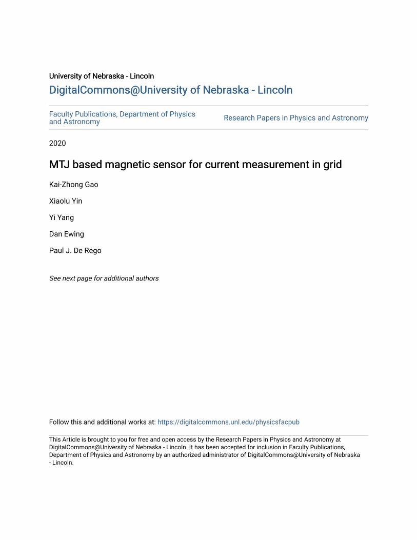
C. DC measurementFigure 3 shows the DC measurement using RemG sensor, cor-
responding to a distance of 1.6 meters between the sensor and theelectric wire. The DC current increases by steps with an incrementof 50 A. The dashed lines are modeling results, assuming that thesensor has a perfect linear response. The percentage numbers ref-erenced here are the differences between the measurement and themodeling results.
The measurement shows a very good repeatability and indicatesthat for this particular case, the sensor response is almost perfectly
FIG. 2. Demonstration of RemG sensor for high frequency AC measurement, thesensor is placed at 1 meter away from a 200 A wire current.
AIP Advances 10, 015301 (2020); doi: 10.1063/1.5129902 10, 015301-2
© Author(s) 2020
AIP Advances ARTICLE scitation.org/journal/adv
FIG. 3. DC measurement using RemG sensor, with step change in wire current vs.perfect linear response from modeling.
linear, with the maximum deviation being within 2%. In addition,the sensor will pick up small current waveform change from the cur-rent source, including the amplitude change, or under-shoot, beforea step is triggered. These results show that the sensitivity of theRemG sensor is high and the response is quick. Note that for Gridapplication, the typical time scale is microsecond or longer, which isseveral orders of magnitude longer than Gyromagnetic precessionalfrequency. The detailed measurement shows signs of magnetic noisedue to thermal fluctuation, but it is not a significant issue for thisparticular study. For the application in the Grid, particularly for DCmeasurement utilized in solar based distributed energy resources(DER), this is not a concern.
III. GRID DETECTION METRICA. Scaling or decay factor
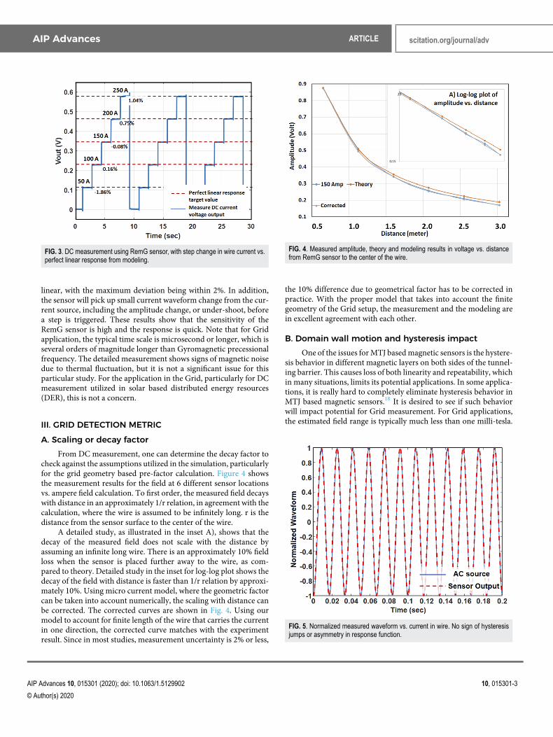
From DC measurement, one can determine the decay factor tocheck against the assumptions utilized in the simulation, particularlyfor the grid geometry based pre-factor calculation. Figure 4 showsthe measurement results for the field at 6 different sensor locationsvs. ampere field calculation. To first order, the measured field decayswith distance in an approximately 1/r relation, in agreement with thecalculation, where the wire is assumed to be infinitely long. r is thedistance from the sensor surface to the center of the wire.
A detailed study, as illustrated in the inset A), shows that thedecay of the measured field does not scale with the distance byassuming an infinite long wire. There is an approximately 10% fieldloss when the sensor is placed further away to the wire, as com-pared to theory. Detailed study in the inset for log-log plot shows thedecay of the field with distance is faster than 1/r relation by approxi-mately 10%. Using micro current model, where the geometric factorcan be taken into account numerically, the scaling with distance canbe corrected. The corrected curves are shown in Fig. 4. Using ourmodel to account for finite length of the wire that carries the currentin one direction, the corrected curve matches with the experimentresult. Since in most studies, measurement uncertainty is 2% or less,
FIG. 4. Measured amplitude, theory and modeling results in voltage vs. distancefrom RemG sensor to the center of the wire.
the 10% difference due to geometrical factor has to be corrected inpractice. With the proper model that takes into account the finitegeometry of the Grid setup, the measurement and the modeling arein excellent agreement with each other.
B. Domain wall motion and hysteresis impactOne of the issues for MTJ based magnetic sensors is the hystere-
sis behavior in different magnetic layers on both sides of the tunnel-ing barrier. This causes loss of both linearity and repeatability, whichin many situations, limits its potential applications. In some applica-tions, it is really hard to completely eliminate hysteresis behavior inMTJ based magnetic sensors.18 It is desired to see if such behaviorwill impact potential for Grid measurement. For Grid applications,the estimated field range is typically much less than one milli-tesla.
FIG. 5. Normalized measured waveform vs. current in wire. No sign of hysteresisjumps or asymmetry in response function.
AIP Advances 10, 015301 (2020); doi: 10.1063/1.5129902 10, 015301-3
© Author(s) 2020

AIP Advances ARTICLE scitation.org/journal/adv
Within this small range, it can be checked for an optimized sensor,whether hysteresis behavior in magnetic layers will generate error inthe field measurement.
Figure 5 shows the normalized AC waveform from the wire andthe measured results from the sensor response. The time delay ofthe response in the detection circuit has been taken into account inthe figure. If hysteresis behavior impacts the measurement and theaccuracy level, a difference between the measured waveform and thecurrent waveform should be observed. The measured results showthat the sensor response is almost perfectly linear and without anysign of hysteresis impact to the accuracy level. Moreover, the mea-surement shows no jumps induced by domain wall motions. To firstorder, RemG sensor can be an excellent option to monitor the Gridcurrent.
IV. CONCLUSIONIn this paper, it is demonstrated that MTJ based mag-
netic sensor can be optimized for Grid monitoring. Based onthe field measurement, the Grid current can be extracted basedon known geometry in real time. And the measurement can bedone in not only AC configuration but also DC configuration.As compared to current technologies in the field,19,20 our tech-nology can meet the desired accuracy level and provide use-ful information in a remote setting. Despite several concernsdue to magnetic hysteresis and nonlinearity associated with MTJand thin film magnetics, it is possible to use RemG technologyto measure the Grid for a given situation with correct model-ing approach. This technology extends the scope of spintronicapplications of MTJ and may provide opportunities for anotherindustry.
ACKNOWLEDGMENTSThis work was supported in part by the International Business
and Technology Service Corporation 201904001 sensor technologyinitiatives. Prior work received support from Honeywell FederalManufacturing & Technologies. The MTJ samples were prepared inthe Nebraska Nanoscale Facility: National Nanotechnology Coor-dinated Infra-structure and the Nebraska Center for Materials andNanoscience, which are supported by the National Science Foun-dation under Award NNCI-1542182, and the Nebraska Research
Initiative. Dr. Kaizhong Gao wants to acknowledge Mr. MarkAhlstrom for his valuable comments on the Grid applications.
REFERENCES1M. Igami and K. Uetake, SSRN (2019).2S. Mao, Y. Chen et al., IEEE Trans. Magn. 42(2), 91 (2006).3Everspin pilot production of 1Gb spin transfer torque MRAM, June 2019,https://finance.yahoo.com/news/everspin-enters-pilot-production-phase-120000858.html.4K. Z. Gao, talks at google, Feb. 2018, https://www.youtube.com/watch?v=nEUf4fMSwMc&t=101s.5S. X. Wang and G. Li, IEEE Trans. Magn. 44(7), 168701702 (2008).6J. Amaral and P. P. Freitas, “Integration of TMR sensors in silicon microneedlesfor magnetic measurements of neurons,” IEEE Trans. Magn. 49(7), 3512–3515(2013).7P. P. Freitas, R. Ferreira, S. Cardoso, and F. Cardoso, J. Phys.: Condens. Matter19, 165221 (2007).8R. Slatter, Proceedings SENSOR, 2015, pp. 228–233.9Y. Ouyang, J. He, J. Hu, G. Zhao, Z. Wang, and S. X. Wang, IEEE Trans. Magn.51(11), 4004204 (2015).10C. Zheng, K. Zhu, S. C. Freitas, J. Y. Chang, J. E. Davies, P. Eames, P. P. Freitas,O. Kazakova, C. G. Kim, C. W. Leung, S. H. Liou, A. Ognev, S. N. Piramanayagam,P. Ripka, A. Samardak, K. H. Shin, S. Y. Tong, M. J. Tung, S. X. Wang, S. S. Xue,X. Yin, and P. W. T. Pong, IEEE Trans. Magn. 55(4), 0800130 (2019).11Q. Huang, Y. Song, X. Sun, L. Jiang, and P. W. T. Pong, IEEE Trans. Magn.50(7), 0900107 (2014).12X. Sun, K. S. Liu, K. K. Y. Wong, W. K. Lee, Y. Hou, Q. Huang, and P. W.T. Pong, IEEE Trans. Magn. 47(10), 2608 (2011).13X. Yin, Y. Yang, Y. F. Liu, J. Hua, A. Sokolov, D. Ewing, P. J. De Rego, K. Z. Gao,and S. H. Liou, Proc. SPIE 11090, 110903H (2019).14K. Z. Gao, US provisional patent application, 2019, K. Z. Gao and S. H. Liou,Electricity Industry Technology and Practices Innovation Challenge (EIT-PIC)Tier II Gold Award, US Department of Energy, Aug. 2019, press release.15T. WEILAND, International Journal of Numerical Modelling 9(4), 295–319(1996).16K. Z. Gao and H. N. Bertram, IEEE Trans. Magn. 38(6), 2063–2065 (2002).17D. Wei, S. Wang, Z. Ding, and K. Z. Gao, IEEE Trans. Magn. 45(8), 3035–3045(2009).18X. Yin, Y. F. Liu, D. Ewing, C. K. Ruder, P. J. Rego, A. S. Edelstein, and S. H. Liou,Proceedings of SPIE 9551, 95512N (2015).19Y. Liu, L. Mili, J. De La Ree, and R. F. Nuqui, CiteSeerX 10.1.1.2.7959 (2001).20T. Rizy, US DOE GMLC Review and Assessment of Sensing and MeasurementTechnology for Electric Power Grids, Feb. 2019, https://gridmod.labworks.org/resources/review-and-assessment-sensing-and-measurement-technology-electric-power-grids.
AIP Advances 10, 015301 (2020); doi: 10.1063/1.5129902 10, 015301-4
© Author(s) 2020