mtnl summer training report
TRANSCRIPT

1
COMPANY PROFILE
MTNL was set up on 1st April, 1986 by the Government of India to upgrade the quality
of telecom services, expand the telecom network, introduce new services and to raise
revenue for telecom development needs of India’s key metros – Delhi, the political
capital and Mumbai, the business capital of India. In the past 17 years, the company has
taken rapid strides to emerge as India’s leading and one of Asia’s largest telecom
operating companies. Besides having a strong financial base, MTNL has achieved a
market share of approximately 13% of the Indian telecommunication network with a
customer base of over 4.74 million lines.
The company has also been in the forefront of technology induction by converting 100%
of its telephone exchange network into the state-of-the-art digital mode.
The Govt. of India currently holds 56.25% stake in the company.
In the year 2002-03, the company has not only consolidated the gains but also focused
on new areas of enterprise viz. Joint Ventures for projects outside India, widened the
cellular and CDMA-based WLL customer base , set up internet and allied services on all
India basis

2
INTRODUCTION
The field of telecommunications has evolved from a stage when signs, drumbeats and
semaphores were used for long distance communication to a stage when electrical, radio and
electro- optical signals are being used. Telecommunication networks carry information
signals among entities, which are geographically far apart. An entity may be a computer, a
human being, a facsimile machine, a teleprinter, a data terminal, and so on. Billions of such
entities the world over are involved in the process of information transfer which may be in
the form of a telephone conversation or a file transfer between two computers or a message
transfer between two terminals. In telephone conversation, the one who initiates the call is
referred to as the calling subscriber and the one for whom the call is destined is the called
subscriber. In other cases of information transfer, the communicating entities are known as
source and destination respectively.
The full potential of telecommunications is realized only when any entity in one part of the
world can communicate with any other entity in another part of the world. Modern
telecommunication networks attempt to make this idea of ‘universal connectivity’ a reality.
Connectivity in telecommunication networks is achieved by use of switching systems.

3
HISTORICAL BACKGROUND
Historically, the transmission of telegraphic signals over wires was the first technological
development in the field of telecommunications. Telegraphy was introduced in 1837 in Great
Britain. In March 1876, Alexander Graham Bell demonstrated his telephone set and the
possibility of telephony, i.e. long distance voice transmission. His demonstration laid the
foundation for telephony. He demonstrated a point-to-point telephone connection. In such a
network, a calling subscriber chooses the appropriate link to establish link with the called
subscriber. In order to draw the attention of the called subscriber before information
exchange can begin, some form of signaling is required with each link. If the called
subscriber is engaged, a suitable indication should be given to the to the calling subscriber by
the means of signaling.
Consequently, the practical use of Bell’s invention on a large or moderate scale demanded
not only the telephone sets and the pairs of wires, but also the Switching System or the
Switching Office or the Exchange. With the introduction of Switching Systems, the
subscribers are not connected directly to one another; instead, they are connected to the
Switching System as shown in the following figure.
S1 S2 Sn-1 Sn
Switching System

4
SUBSCRIBER INTERCONNECTION USING A
SWITCHING SYSTEM
When a subscriber wants to communicate with another, a connection is established between
the two at the switching system. Early switching systems were manual and operator oriented.
Limitations of operator manned switching systems were quickly recognized and automatic
exchanges came into existence. Automatic switching systems can be classified as
electromechanical and electronic. In electronic switching systems, the control functions are
performed by a computer or a processor. The switching scheme used by electronic switching
systems may be either space division switching or time division switching. In space division
switching, a dedicated path is established between the calling and the called subscribers for
the entire duration of the call
SWITCHING SYSTEMS Manual Automatic Electromechanical Electronic Strowger or Crossbar Space division Time division Step-by-step switching switching Digital Analog
Space switch Time switch Combination switch

5
CLASSIFICATION OF SWITCHING SYSTEMS
A modern telecommunication network may be viewed as an aggregate of large number of
point-to-point electrical or optical communication systems. While these systems are capable
of carrying electrical or optical signals, as the case may be, the information to be conveyed is
not always in the form of these signals. For example, the human speech signals need to be
converted to electrical or optical signals before they can be carried by a communication
system. Transducers perform this energy conversion. A medium is required to carry the
signals. This medium, called the channel, may be the free space, a copper cable or the free
space in conjunction with a satellite in case of an electrical communication system. Channels,
in general, are lossy and prone to external noise that corrupts the information carrying
signals. The channel and signal characteristics of individual communication systems in a
telecommunication network may vary widely. For example, the communication system
between the subscriber and the switching system uses most often a pair of copper wires as the
channel, whereas the communication system between the switching systems may use a
coaxial cable or the free space (microwave) as the channel.

6
TELEPHONE NETWORKS
Public switched telephone network (PSTN) or the plain old telephone system (POTS) is
perhaps the most stupendous telecommunication network in existence today. There are over
400 million telephone connections and over 60,000 telephone exchanges the world over. The
length of telephone wire pairs buried underground exceeds a billion kilometers.
Cable hierarchy for subscriber loops
BF BF MF DW BF DC
MDF – main distribution frame
MF – main feeder
FP – feeder point
BF – branch feeder
DP – distribution point
DC – distribution cable
DW – drop wire
M D F
FP
FP
DP DP
DP
DP DP DP
DP
DP DP
FP

7
COMMON CHANNEL SIGNALING
Introduction
The latest signaling being implemented world wide is the Common Channel Signaling. This
type of signaling is essential for setting up of the ISDN network.
In this type of signaling the signaling information is sent from one exchange to other
exchange (Signaling Points) in the form of message coded in Binary which is understandable
by the intelligent devices available in both the exchange. The CCITT organization has
recommended a standard protocol called CCITT#7 signaling.
The signaling message travels over a single time slot of the PCM connecting the two
exchanges. This Time slot is called common channel for Signaling, hence the name common
channel signaling. The message over this common channel carries all the relevant data for
any of the other time slots or circuits which carry voice or subscriber data. The channels for
subs are called Voice Channels.
The OCB-283 exchange uses Common Channel Signaling between its CSN s & the common
control equipments also.
Signaling is often referred to as the Glue, which holds a network together. It provides the
ability to transfer information between subscriber, within networks & between subscriber &
networks. Signaling is the life blood, the vitalizing influence of telecommunications
networks. Without signaling, networks are inert. By providing effective signaling systems, a
network is transformed into a tremendously powerful medium through which subscribers can
communicate with each other using a range of telecommunications services. Old signaling
systems that were simple mechanisms for transferring basic information are being replaced
by efficient data transfer highways.

8
It is signaling that provides the ability for the subscriber to indicate to the exchange that a call
is required. It also allows the called subscriber to be identified e.g. by transferring the
telephone number dialed by calling subscriber.
It allows the transfer of information between exchanges in the network to establish & release
the call. It transforms the foundation of network into an active entity that can provide the
required services to the subscribers. It consists of the instruction, which originate from the
telephone user in the form of lifting the handset in order to make a call, the transmission of
dial pulses generated by operating a dial & replacing a receiver at the end of the call.
Instructions are also signaled by the exchange in the form of dial tone, ringing tone etc., to
indicate the progress of the call. In addition, inter-exchange signaling takes place between a
call is set up, to control exchange operations & check on circuit availability.
EXCHANGE A
EXCHANGE B
EXCHANGE C
VOICE CHANNELS
COMMON CHANNEL FOR SIGNALING
SIGNALING POINTS
COMMON CHANNEL SIGNALING

9
TYPES OF SIGNALING
Telephony started with the invention of magneto telephones, which uses a magneto to generate the
ringing current, the only signal, sent over a dedicated time between two subscribers. As the
switching technology has undergone a vast change from manual switching to Digital switching,
the inter-exchange signaling techniques have also progressively changed from loop no loop
signaling to MF signaling & finally digital signaling. The first digital switching developed was
channel associated signaling in which the signaling information is conveyed on a separate channel
which is rigidly associated channel. The utilization of such a dedicated channel for each speech
channel is highly inefficient, as it remains idle during entire speech phase. Hence a new signaling
system was developed which is capable of providing all new services & is internationally
standardized is known as Common Channel Signaling (CCS#).
Signaling in Pulse Code ModulationSignaling in Pulse Code ModulationSignaling in Pulse Code ModulationSignaling in Pulse Code Modulation
Pulse code modulation (PCM) is a method of converting information from an analoge form to
a digital form for transfer over a digital transmission systems, the technique involves
sampling the analogue waveform & coding the result in the digital format. Successive
sampling allows the analog waveform to be represented by a series of 8 bit code. 8 bit codes
from numerous speech channels are assembled into blocks for transmission by inserting into
time slots. The technique is called Time Division Multiplexing (TDM).
The bandwidth required to transmit signals is much less than that for speech, so the signaling
for several speech channels in a PCM system can be handled by a small portion of the
bandwidth. The signaling capacity can be used for CAS or CSS, the means of identifying to
which speech channel a particular signal refers is to divide the signaling capacity into
dedicated bit locations. Signals pertinent to a particular speech path are always transmitted in
signaling bit locations dedicated to that speech channel. The means of conveying CCS is to
compound the signaling capacity into a signaling channel that is available as & when
required.

10
In 30 channel PCM system, the 8 bit codes relating to 30 speech channels are time division
multiplexed into a frame. Each 8 bit code is inserted into time slot within the frame. Time slot
0 is used for alignment, time slots 1-15 and 17-31 are used for encoded speech relating to 30
channels. Time slot 16 is dedicated for the use of signaling.
The tenet of CAS system is dedicated signaling capacity is available for each speech circuit.
This is achieved in 30 channel PCM systems by allocating 4 bits in each 16 frame multi-
frame to signaling for each speech channel.

11
MAIN DISTRIBUTION FRAME
INTRODUCTION
The switching equipment, common to all the subscribers of the area is located in an
exchange. To make possible for a subscriber to communicate with remaining subscribers,
telephone of each and every subscriber must be connected to the exchange. The function of
MDF is to provide a means for connecting side is terminated at OCB where the switching
takes place. From OCB, through PCM connected to various sections like WLL, TAX etc. A
line from the subscriber’s telephone set involves:
• Subscribers House wiring
• Overhead wires
• Cable Distribution Point
• Underground cables
• Exchange Main Distribution Frame
From the subscriber’s house wiring, the line is brought on overhead wires to a point called
distribution point (DP). From the DP, the pairs are extended to the exchange through
underground distribution cables, secondary cables and primary cables. At the exchange are
brought through underground cables to cable chamber. In the cable chambers, they are
jointed to PVC cables for terminating at MDF. This frame incorporates protecting devices
and provides for a flexible arrangement for connecting subscriber’s lines to exchange
equipments.
SUBSCRIBERS HOUSE WIRING: PVC aluminum twin wire 1or1.12 mm is used
for wiring at subscriber’s house. Protective devices are not necessary at the subscriber’s
premises as per present standards.
UNDERGROUND CABLES: The underground cables lay at a depth to 2.5 feet below
the ground level connect the DP post to the exchange MDF.The cabinets and pillars included

12
in the cable network provide flexible arrangement of interconnection between various sizes
of cables.
FUNCTION OF MDF:
• A fixed means of terminating the external cables.
• A means for mounting the protective devices for incoming circuits.
• A convenient point of interception for locating of faults.
• A means for cross connecting the external circuits to the appropriate internal
circuits.
The MDF is properly earthed for the protection of the equipment. The external pairs are area
wise terminated on the line side of the frame, while connection from the equipment is done
on the exchange side in a numerical order. By interconnections at this frame with the help of
jumper wires, any subscriber in any area can be given any exchange number. This MDF
mounts Delay
.

13
OCB 283 DIGITAL ELECTRONIC SYSTEM
Introduction
OCB 283 is digital switching system which supports a variety of communication needs
like basic telephony, ISDN, interface to mobile communication, data communication etc.
this system has been developed by ALCATEL of France and therefore has many
similarities to its predecessor E-10B (also known as OCB 181 in France).
The first OCB 283 exchanges of R11version were commissioned in Brest (France) and
Beijing (China) in 1991.The first OCB-283 exchange came to India in 1993. Subsequently,
the system has been upgraded and current version R20 was fully validated in January 1994.
The exchanges, which are being supplied to India, belong to R20 version. At present, R21
R22 versions are also being supplied. The basic architecture remaining same, more
facilities both to subscribers and administration are supported by later versions.
OCB 283 is a multi service Switching System which can serve as Local, TAX, Tandem,
International Gateway Exchange.
ComponentsComponentsComponentsComponents
The Exchange has three parts :
1. Control Part
2. Subscriber Part
3. Operation and Maintenance Center (OMC)
It has basically five modules of control :
1. SMX- Switch Management System
2. SMT- Trunk Management System
3. SMA-Auxiliary Management System
4. SMC-Control Management System
5. SMM- Maintenance Management System
6. STS-Synchronization and Time Based Station

14
Facilities to Digital SubscribersFacilities to Digital SubscribersFacilities to Digital SubscribersFacilities to Digital Subscribers
Digital subscribers are provided all the facilities available to analogous subscribers. In
addition, they are provided following facilities, which are called ISDN, services. An ISDN
subscriber can use many electronic devices on its telephone line and can utilize them for 2 or
more simultaneous calls of either
• VOICE
• DATA
• VIDEO
The ISDN or Digital Subscribers of OCB 283 can be provided the following types of
connections
• 2 B+D Line: - 2 Voice Channels of 64 kbps & 1 Data Channel for 16 kbps
• 30 B+D Line: - 30 Voice Channels of 64 kbps & 1 Data Channel for 64 kbps
The following is the list of some of the services to Digital Subscribers
a) It provides 64 Kbps digital connectivity between two subscribers for data
communication.
b) The system can provide Group 2, 3 or 4 Facsimile (FAX) services.
c) It provides videotext services.
d) The system provides display of calling subscriber number on the called subscriber
telephone.
e) The system also provides the facility for restriction of the display of calling subscriber
number on called subscriber’s terminal. To avail this facility, the subscriber has to be
given a category.
f) The system provides the facility of displaying connected number on the calling
subscriber terminal. This is especially useful when called subscriber has activated
‘call transfer facility’. The calling subscriber can choose to speak on forwarded
number or disconnect the call.
g) The above facility can be restricted by giving special category to the subscriber.
h) Charging advice – The system is capable of providing charging advice either in real
time or at the end of the call.

15
i) User to user signaling – The system permits transfer to mini messages between calling
and called subscribers during call set up and ringing phase.
j) Terminal portability during the call – A subscriber (calling subscriber as well as
called subscriber) can unplug the terminal, carry it to some other place or room and
resume the call within 3 minutes.
k) Listing unanswered calls – The number of calling subscribers, who calls during the
absence of called subscriber, are recorded in called subscriber’s terminal. The called
subscriber can then check up these numbers and call them back if, he so wished.

16
OCB-283 SWITCHING SYSTEM
The functional architecture of the OCB-283 System comprises generally of following distinct
components:
Connection units
These provide facility to connect subscribers loop or circuits from an external PCM and
transfer these Speech samples on to selected Time Slots called voice channels on a LR link
(internal PCM) towards switching matrix & vice versa. These units are
NAME FUNCTIONAL NAME
Subscriber Connection Units
Circuit Connection Units
Frequency Generator, Sender & Receiver & Common
Channel Signaling Protocol Handler
CSNL, CSND, CSED
SMT (URM)
SMA (ETA)
SMA (PUPE)
Switching Network
These provide facility for connecting the LR s (internal PCM s) coming from connection
units and performs Switching Operation for Calling Subs TS onto Called subscriber TS &
vice versa for a two-way connection per call of telephony.
Control Units
These units provide control of calls on the basis of Stored programs. They process the calls
on reception of dialed digits from calling subscriber/ circuit & take part in handling of call
set-up & release by processing, monitoring, measuring charging of calls & all other common
control functions are needed for working of an Automatic Common Control Exchange.
These Control units can comprise of following functions

17
NAME OF FUNCTION FUNCTION
MR: Multiregister
TR: Translator
MQ: Marker
TX: Charger
GX: Matrix System Handler
PC: Common Channel Signaling
Network controller
Call handler SET UP & RELEASE OF CALL
Translation of digit, Databank of subs & circuits in
files
Message distribution between Common Control &
Connection units
Computing the charge of a call, keeping meters
Processes & makes connections in Switching matrix
on the orders from MR or MQ
Manage the CCS7 network for signaling
O&M Units & Maintenance peripherals
In an Electronic Stored Program Control Digital Exchange OCB-283, all operation &
maintenance activities are performed by a unit called OMC (Operation & Maintenance
Centre).
This provides access for Man Machine dialogues for the human operators to interact and
command the working of Exchange Equipments.

18
OPERATION AND MAINTENANCE
This topic describes:
� The purpose of operation and maintenance,
� The role of the operator
PURPOSE OF OPERATION AND
MAINTENANCE
The routine management operations are for maintaining the reliability and
Performance of the Alcatel 1000 E10 (OCB283) system.
A well-managed operation and maintenance function can:
� ensure the performance of the exchange,
� ensure the ongoing availability and quality of transmission resources,
� provide uninterrupted mobility for subscribers (mobile network and call forwarding
services),
� provide total quality from end to end,
� allow for the rapid introduction of services,
� provide service availability,
� enable faults to be repaired quickly,
� provide good quality of service to subscribers,
� Ensure effective traffic handling.

19
BROADBAND Broadband is a wide bandwidth data transmission with an ability to simultaneously transport multiple signals and traffic types. The medium can be coaxial cable, optical fiber, radio or twisted pair. Internet access an ‘always-on' data connection that is able to support interactive services including.
� According to Broadband policy 2004, has the capability of the minimum download speed of 256 kilobits per second (kbps) to an individual subscriber from the Point Of Presence (POP) of the service provider.
� According to New Telecom policy 2011, minimum download speed should be 512 kbps.
� It provides Internet, IPTV and VoIP simultaneously along with basic telephone service.
Asymmetric digital subscriber line (ADSL) Asymmetric digital subscriber line (ADSL) is a type of digital subscriber line (DSL) technology, a data communications technology that enables faster data transmission over copper telephone lines than a conventional voice band modem can provide. ADSL differs from the less common symmetric digital subscriber line (SDSL). Bandwidth (and bit rate) is greater toward the customer premises (known as downstream) than the reverse (known as upstream). This is why it is called asymmetric. Providers usually market ADSL as a service for consumers to receive Internet access in a relatively passive mode: able to use the higher speed direction for the download from the Internet but not needing to run servers that would require high speed in the other direction. Adsl modem

20
Frequency spectrum used in Broadband
Digital subscriber line (DSL)
XDSL, is a family of technologies that provides digital data transmission over the wires of a local telephone network
� DSL (Digital Subscriber Line) exploits the unused analogue bandwidth that is potentially available in the wires that run from the user premises to the local exchange
� The phone system nominally passes audio between 0.3 KHz and 3.4 KHz, which is regarded as the range required for human speech to be clearly intelligible. This is known as voice band or commercial bandwidth
� The local loop connecting the telephone exchange to most subscribers is capable of carrying frequencies well beyond the 3.4 kHz upper limit of POTS.
� DSL takes advantage of this unused bandwidth of the local loop for carrying data.
4 KHz 26 KHz 138 KHz 1 . 1 MHz
UPSTREAM DOWNSTREAM
21
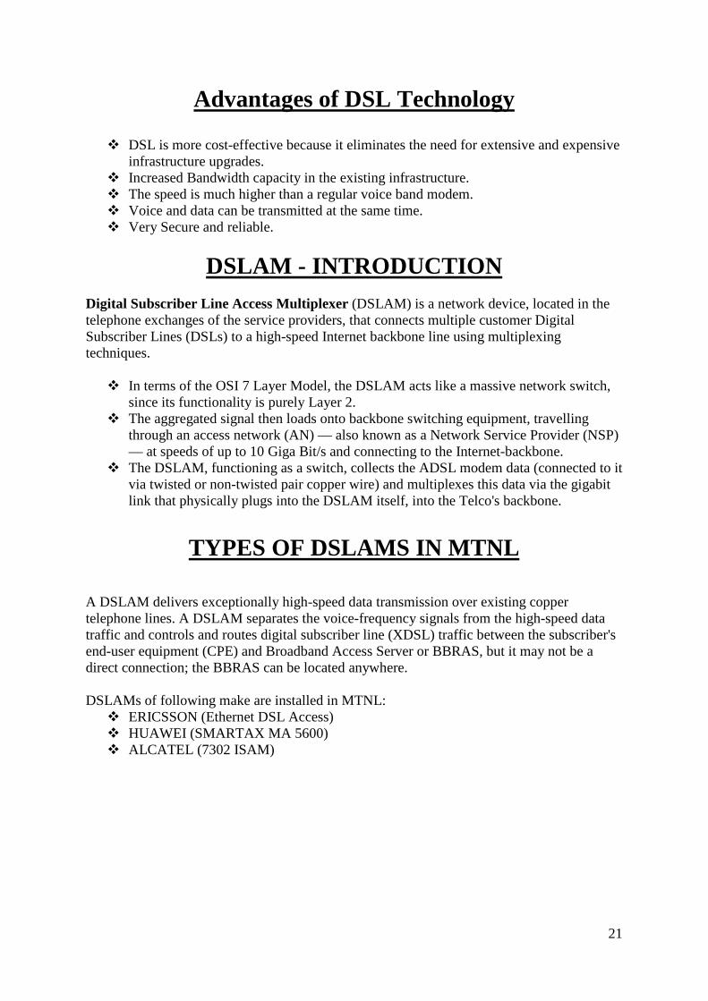
Advantages of DSL Technology
� DSL is more cost-effective because it eliminates the need for extensive and expensive infrastructure upgrades.
� Increased Bandwidth capacity in the existing infrastructure. � The speed is much higher than a regular voice band modem. � Voice and data can be transmitted at the same time. � Very Secure and reliable.
DSLAM - INTRODUCTION Digital Subscriber Line Access Multiplexer (DSLAM) is a network device, located in the telephone exchanges of the service providers, that connects multiple customer Digital Subscriber Lines (DSLs) to a high-speed Internet backbone line using multiplexing techniques.
� In terms of the OSI 7 Layer Model, the DSLAM acts like a massive network switch, since its functionality is purely Layer 2.
� The aggregated signal then loads onto backbone switching equipment, travelling through an access network (AN) — also known as a Network Service Provider (NSP) — at speeds of up to 10 Giga Bit/s and connecting to the Internet-backbone.
� The DSLAM, functioning as a switch, collects the ADSL modem data (connected to it via twisted or non-twisted pair copper wire) and multiplexes this data via the gigabit link that physically plugs into the DSLAM itself, into the Telco's backbone.
TYPES OF DSLAMS IN MTNL
A DSLAM delivers exceptionally high-speed data transmission over existing copper telephone lines. A DSLAM separates the voice-frequency signals from the high-speed data traffic and controls and routes digital subscriber line (XDSL) traffic between the subscriber's end-user equipment (CPE) and Broadband Access Server or BBRAS, but it may not be a direct connection; the BBRAS can be located anywhere. DSLAMs of following make are installed in MTNL:
� ERICSSON (Ethernet DSL Access) � HUAWEI (SMARTAX MA 5600) � ALCATEL (7302 ISAM)

22
ERICSSON
ALCATEL-LUCENT
HUAWEI
23
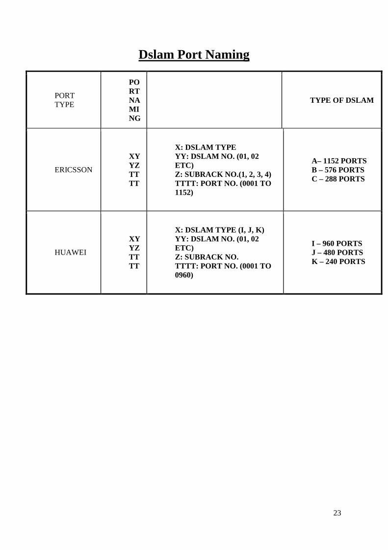
Dslam Port Naming
PORT TYPE
PORT NAMING
TYPE OF DSLAM
ERICSSON
XYYZTTTT
X: DSLAM TYPE YY: DSLAM NO. (01, 02 ETC) Z: SUBRACK NO.(1, 2, 3, 4) TTTT: PORT NO. (0001 TO 1152)
A– 1152 PORTS B – 576 PORTS C – 288 PORTS
HUAWEI
XYYZTTTT
X: DSLAM TYPE (I, J, K) YY: DSLAM NO. (01, 02 ETC) Z: SUBRACK NO. TTTT: PORT NO. (0001 TO 0960)
I – 960 PORTS J – 480 PORTS K – 240 PORTS

24
PHYSICAL CONNECTIONS

25
DSLAM (DSL Access Multiplexer)
Within the block identified as 'Service provider', there are three important components: DSLAM - DSL Access Multiplexer A Digital Subscriber Line Access Multiplexer (DSLAM) is a network device, usually at a telephone company central office, that receives signals from multiple customer Digital Subscriber Line (DSL) connections and puts the signals on a high-speed backbone line using multiplexing techniques. BBRAS - Broadband Remote Access Server The BBRAS is the piece of equipment that sits between the DSLAM at the telephone exchange and the ISP that connects to the Internet. ISP - Internet Service Provider The Broadband Access Servers are connected to an Internet Service Provider or ISP. This is the place where the connection to the Internet is made.
Connectivity to Gateways All the internet traffic is coming from DSLAM to T2, the from T2 to T1, from T1 to BBRAS as layer 2 traffic. All the BBRAS's are connected to Two switches (known as Aggregation A and Aggregation B) using fiber cable. And these switches are connected to two gateways routers (4th floor and 9th floor) with six pairs of fibers. That is from Aggregation-A Three pairs of fibers are going to gateway 1 and three pairs of fibers are going to gateway 2. Same is the case with Aggregation - B switch.
ADSL
Bandw
LOC
AL
LOO

26
Ericsson Broadband Network
RADIUS
� Remote Authentication Dial In User Service � Concept of AAA � Authentication � Authorization � Accounting

27
How Broadband Service Works?
3、、、、 Authentication
system checks
account &password
;;;;BRAS allocates
valid IP BBRAS
Radius
Server
Lan
switch
Cor
e
R
5、、、、Billing
server start
accounting
2、、、、PPPoE
session
ends here
and session
ID is
allocated
1、、、、PPPo
E is
initiated
by
subscrib
er
4、Subscribe
r gets IP and
visit Internet

28
BB Service Flow
PC ����CPE���� DSLAM ���� T2���� T1 ����BRAS
Service flow begins from Client �BRAS which terminated PPP sessions.
The process for user connection to internet is:
� Client starts pppoe session by using pppoe software. � ADSL modem translates IP packets into ATM cell. � DSLAM recovers ATM cells to IP packets. � vlan /vmac tag to the recovered IP packets. Each user has a DSLAM uses Q-in-Q
protocol/VMAC, which adds a new respective vlan/vmac. � T2 forwards IP packet to T1 & T1 transfers the IP packets to BRAS. � BRAS also supports Q-in-Q protocol /vmac according to different outer vlan and
inner vlan to identify Different users.
T1/T2/Aggregation/NOC Switches Definition: They are LAN switches used for aggregating and cross-connecting clients, servers and other network devices. Devices used in MTNL: 3COM 7700 LAN Switches (ERICSSON) and NE80E T-1 Switch, S6506 T-2 Switch (HUAWEI)
Broadband Remote Access Server (BRAS)
A broadband remote access server (BRAS, B-RAS or BBRAS) routes traffic to and from broadband remote access devices such as digital subscriber line access multiplexers (DSLAM) on an Internet service provider's (ISP) network. BRAS can also be referred to as a Broadband Network Gateway. The BRAS sits at the core of an ISP's network, and aggregates user sessions from the access network. It is at the BRAS that an ISP can inject policy management and IP Quality of Service.

29
INTRODUCTION TO GSM GSM is known as Global System for Mobile Communication. A technology developed in
1985 by a French company known as Group Special Mobile.
Cellular radio provides mobile telephone service by employing a network of cell sites
distributed over a wide range. A cell site contains a radio transceiver and a base station
controller, which manages, sends, and receives traffic from the mobiles in its geographical
area to a cellular phone switch. It also employs a tower and its antennas, and provides a link
to the distant cellular switch called a mobile telecommunication switching office. This MTSO
places calls from land based telephones to the wireless customers, switches calls between
cells as mobile travel across cell boundaries, and authenticates wireless customers before they
make calls.
GSM calls are either based on data or voice. Voice calls use audio codes called half-
rate, full-rate and enhanced full-rate. Data calls can turn the cell phone into a modem
operating at 9600 bps.
It uses digital technology and time division multiple access transmission method Voice is digitally encoded via a unique encoder, which emulates the characteristics of human speech. This method of transmission permits a very efficient data rate/information content ratio.
One of its great strength is the international roaming capability that gives consumers
seamless and same standardized same number contact ability in more than 170 countries.
GSM satellite roaming has extended service access to areas where terrestrial coverage is not
available.
GSM technology is continually evolving. Having made great leaps forward in the past 10 years. It is facing an even greater evolution in the years ahead

30
.
HISTORY OF GSM The first mobile telephone service started in 1946 in St. Louis, Missouri, USA as a manually
operated system. Between 1950 and 1960, it evolved as an automatic system with reduced
cost and increased, but small subscriber base. Mobile telephony service in its useful form
appeared in 1960s.
The period from 1940 – 60
• The 1st mobile telephone service started in 1946 in St. Louis Missouri, USA. • Between 1950 and 1960 it evolved as an automatic system. • Mobile telephony service in its useful from appeared in 1960s.
The period from 1980 - 95
• Each country developed its own system
• In 1982 the Conference of European Posts and Telegraphs (CEPT) formed a
study group called the Group Special Mobile (GSM) to study and develop a
European public land mobile system which had to meet certain criteria :
Good subjective speech quality. Low terminal and service cost. Support for international roaming Ability to support hand held terminals. Support for range of new service and facilities. Spectral efficiency.
In 1989, GSM responsibility was transferred to European Telecommunication
Standards Institute (ETSI)
GSM specifications were published in 1990 as:- Commercial service started in mid – 1991 By 1993 there were 36 GSM networks in 22 countries

31
The First Generation Mobile Communication System appeared in 1970s and remained till
1980s.They used analog transmission techniques for radio link and confined its users to their
respective systems areas for which the mobile phone was designed. Capacity of system was
limited and roaming between the coverage areas of different systems was impossible. Apart
from being very expensive these system provides very poor QoS and supported only voice
communication.
The Second Generation Mobile Communication System has grew out of the limitation of
first generation systems. They supported large subscriber base, carried both voice and data
and have capable of design and deliver new value added services. GSM and CDMA emerged
as the trend setting technologies. The domination of 2G systems became apparent in second
half of 1990s.
The Third Generation Mobile Communication Systems provide high functionality with
seamless global roaming. Apart from providing very high data rates, 3G systems seek to
integrate the wire line systems with mobile systems. 3G would provide users consistent
voice, data, graphical, multi-media regardless of their location in the network. They also
integrate the Intelligent Network (IN) capabilities into mobile systems.
Cellular Principal and Mobility Issues: -
In mobile communication the wired 2W subscriber line is replaced with a wireless mobile
link. Once the customer is liberated from the confines of the wire and made free to move, the
following issues arise:-
• Demand on the scarce radio resources. • Authentication of the customer. • Security and privacy on the radio

32
• Provide unique service profile. • Keep track of the user as they move. • Proving service across networks. • Billing the customer whenever and wherever he makes and receives calls from.
An important issue in mobile communication is the need to authenticate the genuineness of
the customer whenever he receives or attempts to make communication. Since the media
being open space, it is necessary to verify whether the customer is the one whom he claims to
be before resources allocation. Security of the mobile account is to be ensured to prevent
unauthorized use and also misuse of one’s subscription. Privacy of the communication over
radio is to be ensured though the radio signals are available everywhere for interception.
One of the important issues for the customer is the availability of seamless service profile
irrespective of his location. This is an essential feature of the mobile communication,
particularly when the customer visits a service area served by an operator different from his
own. Different dialing codes for accessing the same service in different networks can lay
havoc in realizing the services by the customer.
Yet another challenging issue in mobile communication is the need to keep track of the
customer’s location so that an incoming call can be connected to him. Equally important is
the need to main established

33
Cell To Mobile – Down Link
935-960 Mhz
1805-1880 Mhz
Mobile to Cell – Up Link
890-915 Mhz
1710-1785 Mhz

34
A comparison of typical PSTN and mobile call scenarios is shown in figure The central concept that made mobile communication as a usable commercial proposition is
the cellular principle. BELL Laboratories, US in 1970 first introduced cellular principle
Under cellular concept, the service area is divided into a number of CLUSTERS, each cluster
consists of a number of CELLS and each cell is assigned as many CARRIERS as required by
the traffic in that cell. There is a one-to-one correspondence between the cells in each of the
clusters that these cells use the same carrier frequencies.
Since the frequency used being the same, the principle of frequency reuse demands that the
interference between them when serving different cells and therefore different customers
should be kept within permissible limits
35
Above figure shows a 7-CELL reuse pattern. The 7 cells, shown as seven different hexagons
that are tagged in contiguity are called a cluster. The cluster is repeated in such a manner that
the distance between the cells using the same frequency is kept as far as possible.
INTRODUCTION A GSM system is basically designed as combination of 3 major subsystems:
• Network subsystem
• Radio subsystem
• Operation support subsystem In order to ensure that network operators will have several sources of cellular infrastructure
equipment, GSM specify not only the air interface, but also the main interfaces that identify
different parts.
GSM NETWORK STRUCTURE Every telephone network needs a well designed structure in order to route incoming called to
the correct exchange and finally to the called subscriber. In a mobile network, this structure
is of great importance because of the mobility of all its subscribers. In GSM system, network
is divided into following partitioned areas:-
GSM service area: - It is the total area served by the combination of all member countries
where a mobile can be serviced.
PLMN service area: - Based on its size these can be several within a country. All incoming
calls for a GSM/PLMN network will be routed to a gateway MSC which works as an
incoming transit exchange. The gateway MSC consists the inter working functions to make
these connections.
MSC service area: - There can be several MSC / VLR in one PLMN . To route a call to a mobile subscriber, the path through links to MSC in the MSC area where the

36
subscriber is currently located. The mobile location can be uniquely identified since the MS
is registered in a VLR, which is generally associated with an MSC.
Location areas :- LA’s are several within a MSC/VLR combination. A LA is a part of the
MSC/VLR service area in which a MS may move freely without updating location
information to the MSC/VLR exchange that control the LA. In a LA a paging message is
broadcast to find the called mobile subscriber. LA can be identified by using the location area
identity. LA is used to search for the subscriber in an active state.
Cells :- It is an identity served by one BTS The MS differentiate between cells using BSIC
(Base Station Identification Code) that the cell site broadcast over the air.
Figure shows an overview of GSM Architecture
MOBILE STATION The mobile station (MS) includes radio equipment and the man machine interface that a
subscriber needs in order to access the service provided by the GSM PLMN. The MS may
include provisions for the data communication as well as voice. A mobile transmits and

37
Receives message to and from the GSM system over the air interface to establish and
continue connections through the system.
Each MS is identified by an IMEI that is permanently stored in a mobile unit. Upon request,
the MS sends this number over he signaling channel to the MSC. The IMEI can be used to
identify mobile units that are reported stolen or operating incorrectly.
The mobile subscriber ISDN number (MS ISDN) is the number that the calling party dials in
order to reach the subscriber. It is used by the land network to route calls towards an
appropriate MSC. The international mobile subscriber identity (IMSI) is permanently
assigned to him. Temporary mobile subscriber identity (TMSI) is also assigned by the GSM
system which can be periodically changed and protect the subscriber from being identified by
those attempting to monitor the radio channel.
FUNCTIONS OF MOBILE STATION
• The primary functions of MS are to transmit and receive voice and data over the Air
interface of the GSM system. MS performs the signal processing function of digiting,
encoding, error protecting, encrypting, and modulating the transmitted signals. It also
performs the inverse functions on the received signals from BS.
• In order to transmit voice and data signals, the mobile must be in
synchronization with the system.
• To achieve this, the MS automatically tunes and synchronizes to the frequency
and TDMA timeslot specified by the BSC.
• The MS monitors the power level and signal quality, determined by the BER for
known receiver bit sequences from both its current BTS and up to six surrounding
BTSs. This data is received on the downlink broadcast control channel. The system
then uses this list for best cell handover decisions.
• MS keeps the GSM network informed of its location during both national
and international roaming, even when it is inactive.
• MS includes an equalizer that compensates for multi path distortion on the
received signal
• The MS can store and display short received alphanumeric messages on the LCD.
These messages are limited to 160 characters in length.

38
SIM CARD GSM subscribers are provided with a sim card with its unique identification at the very
beginning of the service. The suscriber is identified in the system when he inserts the SIM
card in the mobile equipment. The smart card SIM is potable between Mobile equipment
(MS) units. The user only needs to take his smart card on a trip because it can be used in any
GSM specified mobile set. He can then a ME unit at the destination, even in the another
country, and insert his own SIM. Also, the GSM system will be able to reach him at the ME
unit he is currently using.
The SIM is a removable card, containing an integrated circuit chip with a microprocessor,
random access memory (RAM), and read only memory (ROM). The subscriber inserts it in
the MS unit when he or she wants to use the MS to make or receive a call.
INTERNATIONAL MOBILE SUBSCRIBER IDENTITY An IMSI assigned to each authorized GSM user. It consists of a mobile country code (MSC),
mobile network code (MNC), and a PLMN unique mobile subscriber identification number
(MSIN). The IMSI is not hardware-specific. Instead, it is maintained on a SC by an
authorized subscriber and is only absolute identify that a subscriber has within the GSM
system.
TEMPORARY MOBILE SUBSCRIBER IDENTITY A TMSI is a MSC-VLR specific alias that is designed to maintain user confidentiality. It is
assigned only after successful subscriber authentication. The correlation of a TMSI to an IMSI only occurs during a mobile subscriber’s initial transaction with an MSC (for example,
location updating). Under certain conditions (such as traffics system disruption and
malfunctioning of the system), the MSC can direct individual TMSIs to provide the MCS
with their IMSI.
THE MOBILE STATION ROAMING NUMBER (MSRN) The MSRN is allocated on temporary basis when the MS roams into another numbering area.
The MSRN number is used by the HLR for rerouting calls to the MS. It is assigned upon
demand by the HLR on a per-call basis. The MSRN for PSTN/ISDN routing shall have the

39
same structure as international ISDN numbers in the area in which the MSRN is allocated.
The HLR knows in what MSC/VLR service area the subscriber is located. At the reception of
the MSRN, HLR sends it to the GMSC, which can now route the call to the MSC/VLR
exchange where the called subscriber is currently registered.
BASE STATION SYSTEM The BSS is a set of BS equipment (such as transceivers and controllers) that is the entry
responsible for communication with Mobile Stations in a certain area. A BSS may consist of
one or more BS. The BSS includes two types of machines: -
• The BTS in contact with the MSs through the radio interface.
• The BSC the latter being in contact with the MSC.
BTS A BTS compares radio transmissions and reception devices, up to and including the antennas,
and also all the signal process specific to the radio interface.
A BTS is a network component that serves one cell and is controlled by a BSC. A BTS is
typically able to handle 3 to 5 radio carriers, carrying between 24 and 40 simultaneous
communications.
An important component of the BSS that is considered in the GSM architecture as a part of
the BTS is the Trans coder/Rate Adapter Unit (TRAU). The TRAU is the equipment in which
coding and decoding is carried out as well as rate adoption in case of data. Although the
specifications consider the TRAU as a subpart of the BTS, it can be sited away from the BTS
(at MSC), and even between the BSC and the MSC.
FUNCTIONS OF BTS
• The primary responsibility of BTS is to transmit and receive radio signals from a
mobile over as air interface. To perform this function completely the signals are
encoded, encrypted, multiplexed, modulated and then fed to the antenna system at the
cell site. Transcoding to bring 13-kbps speech to a standard data rate of 16kbps and
then combining four of these signals to 64 kbps is essentially a part of BTS.

40
• The received signals from the mobile is decoded, decrypted, and equalized for
channel impairments.
• Random access detection is made by BTS, which then sends the messages to BSC.
The channel subsequent assignment is made by BSC. BSC BTS to notify the MS to advance the timing such that proper synchronization takes place The
BSC is connected to the MSC on one side and to the BTS on the other. The BSC performs
the Radio Resource (RR) Management for the cells under its control. It assigns and release
frequencies and timeslots for all MSs in its own area. It also reallocates frequencies to the
BTSs in its area to meet locally heavy demands during peak hours or on special events. The
BSC controls the power transmission of both BSSs and MSs in its area. The minimum power
level for a mobile unit is broadcast over the BCCH. The BSC provides the time and
frequency synchronization reference signals broadcast by its BTSs. The BSC also measures
the time delay of received MS is not centered in its assigned timeslot at the BTS, the BSC can
direct the.
FUNCTIONS OF BSC
• The BSC also performs traffic concentration to reduce the number of transmission
lines from the BSC to its BTSs, as discussed in the last section.
SWITCHING SUBSYSTEMS MOBILE SWITCHING CENTRE AND GATEWAY SWITCHING
CENTRE The network and the switching subsystem together include the main switching functions of
the GSM as well as the databases needed for the subscriber data and the mobility
management (VLR). The main role of the MSC is to manage the communication between the
GSM users and other telecommunication network users. The basic switching functions are
performed by the MSC whose main function is to coordinate setting up calls to and from

41
GSM users. The MSC has interface with the BSS on the one side and the external networks
on the other. The main difference between MSC and EXCHANGE in a fixed network is that
the MSC has to take into account the impact of the allocation of RRs and the mobile nature of
subscribers and has to perform.
VARIABLE LOCATION REGISTER The VLR is collocated with an MSC. A MS roaming in an MSC area is controlled by the
VLR responsible for that area. When a MS appears in a LA it starts a registration procedure.
The MSC for that area notices this registration and transfers to the VLT, the identity of the LA where the MS is situated. A VLR may be in charge of one or several MSCs LA’s. the VLR constitutes the databases that support the MSc in the storage and retrieval of the data of
subscribers present in that area. When an MS enters the MSCs area borders, it signals its
arrival to the MSC that stores its identity in the VLR. The information necessary to manage
the MS is contained in HLR and is transferred to the VLR so that they can be easily retrieved
if so required.
PLMN may contain VARIABLE LOCATION REGISTER The VLR is collocated with an MSC. A MS roaming in an MSC area is controlled by the
VLR responsible for that area. When a MS appears in a LA it starts a registration procedure.
The MSC for that area notices this registration and transfers to the VLT, the identity of the LA where the MS is situated. A VLR may be in charge of one or several MSCs LA’s. the

42
VLR constitutes the databases that support the MSc in the storage and retrieval of the data of
subscribers present in that area. When an MS enters the MSCs area borders, it signals its
arrival to the MSC that stores its identity in the VLR. The information necessary to manage
the MS is contained in HLR and is transferred to the VLR so that they can be easily retrieved
if so required.
HOME LOCATION REGISTER
• HLR is a database that permanently stores data related to a given set of subscribers.
• Various identification numbers and addresses as well as authentication parameters,
services, special routing information are stored.
• Current subscriber status including a subscriber’s temporary roaming number
and associated VLR if the mobile is roaming are maintained.
• HLR is responsible for storage and provision of SIM authentication and encryption
parameters form the AUC.
• one or several HLRs.
AUTHENTICATION CENTER
• The AUC stores information that is necessary to protect communication through the
air interface against intrusions, to which the mobile is vulnerable.
• The legitimacy of the subscriber is established through authentication and ciphering,
which protects the user information against unwanted disclosure.
• Authentication information and ciphering keys are stored in a database within the
AUC which protects the user information against unwanted disclosure and access.
EQUIPMENT IDENTIFY REGISTE R EIR is a database that stores the IMEI numbers for all registered ME units. The IMEI
uniquely identifies all registered ME. There is generally one EIR per PLMN. It interfaces to
the various HLR in the PLMN. The EIR keeps track of all ME units in the PLMN. It
maintains various lists of message. The database stores the ME identification and has nothing
do with subscriber who is receiving or originating call. There are three classes of ME that are
stored in the database, and each group has different characteristics.

43
• White List: contains those IMEIs that are known to have been assigned to valid MS’s.
This is the category of genuine equipment.
• Black List: contains IMEIs of mobiles that have been reported stolen.
• Gray List: contains IMEIs of mobiles that have problems (for example, faulty
software, wrong make of the equipment). This list contains all MEs with faults not
important enough for barring.
INTERWORKING FUNCTION GSM provided a wide range of data services to its subscribers. The GSM system interface
with the various forms of public and private data network currently available. It is the job of
the IWF to provide this interfacing capability.
The IWF, which is essence is a part of MSC, provides the subscriber with access to data rate
and protocol conversion facilities so that data can be transmitted between GSM Data
Terminal Equipment (DTE) and a land-line DTE
ECHO CANCELER EC is use on the PSTN side of the MSC for all voice circuits. The EC is required at the MSC
PSTN interface to reduce the effect of GSM delay when the mobile is connected to the PSTN
circuit. The total round-trip delay introduced by the GSM system, which is the result of
speech encoding, decoding and signal processing is of the order of 180 ms. The standard echo
canceller cancels about 70 ms of delay.
As the GSM round-trip delay added and without the EC the effect would be irritating to the
MS subscriber. FUNCTIONS OF MSC
• As stated, the main function of the MSC is to coordinate the set up of calls between GSM mobile and PSTN users. Specifically, it performs functions such as paging, resource allocation, location registration, and encryption.

44
• The MSC is a telephony switch that performs all the switching functions for MSs
located in a geographical area as the MSC area. The MSC must also handle different types of numbers and identities are used in the fixed part of the network, such as, for routing.
• The call-handling function of paging is controlled bt MSC. MSC coordinates the set up of paging is controlled in different registers: IMSI, TMSI, ISDN number and MSRN. In general identities are used in the interface between the MSC and the MS, while numbers are used in the fixed part of the nrtwork, such as, for routing.
• The call-handling function of the paging is controlled by MSC. MSC coordinates the set up of call to and from all GSM subscribers operating in its areas. The dynamics allocation of access resources is done in coordination with the BSS. More specifically, the MSC decides when and which types of channels should be assigned to which MS. The channel identity and related radio parameters are the responsibility of the BSS; The MSC provides the control for the subscriber authentication procedure.
• The MSC supervises the connection transfer between different BSSs for MSs, with an active call, moving from one call to another. This is ensured if the two BSSs are connected to the same MSC but alsowhen they are not. In this later case the procedure s more complex, since more than one MSC is involved.
• The MSC performs billing on calls for all subscribers based in its areas. When the subscriber is in roaming elsewhere, the MSC obtains data for the call billing from the visited MSC.
• Encryption parameters transfers from VLR to BSS to facilitate ciphering on the radio interface are done by MSC. The exchange of signaling information on the various interface toward the other network elements and the management of the interfaces themselves are all controlled by the MSC.
• The MSC serves as a SMS gateway to forward SMS messages from Short Message Service Centers (SMSC) to the subscribers and from the subscribers to the SMSCs. It thus acts as a message mailbox and delivery system.
OVER VIEW OF THE GSM INTERFACE :- For the connection of the different nodes in GSM network, different interface are defined in
GSM specifications which are discussed as below :-
Air Interface Or U m – Interface:- This interface is between the BTS (Base Transceiver Station) and the MS (Mobile Station).
To achieve a high spectral efficiency in a cellular network a combination of :-
• FDMA (Frequency Division Multiple Access)
• TDMA (Time Division Multiple Access)

45
A Bis -- Interface :- The A Bis – interface is the interface between the BSC (Base Station Controller) and the
BTS. The interface companies traffic and control channels.
A – Interface :- The a – Interface is the interface between the BSC and the MSC. Logical Channels on the Um-Interface:- One or more logical channels may be transmitted on physical channel. The different type of logical channel is determined by the function of the information transmitted over it. The following types of logical channels are defined :-
• Traffic channels • Broadcast Channels • Common Control Channels • Dedicated Control Channels
The first channel type carries speech and data and the other types control information
(signalin

46
References:
� https://en.wikipedia.org/wiki/Broadband � https://en.wikipedia.org/wiki/Switching_circuit_theory � https://en.wikipedia.org/wiki/Mahanagar_Telephone_Nigam � https://en.wikipedia.org/wiki/Centre_for_Excellence_in_Telecom_Technology
_and_Management � http://www.ijitee.org/attachments/File/v1i6/E0333101612.pdf � https://en.wikipedia.org/wiki/GSM � The GSM system for mobile communication � GSM system engineering � Beddous E.W.,”GSM Network Architecture’s Seminar � Mouly M and pautet Marie-Bernedette,”Current Evolutin of the GSM system � Data Communications and Networking-Behrouz A. Forouzan � Telecommunication Switching Systems and Networks-Thiagrajan
Viswanathan. � http://mtnldelhi.in/