mu uuuu ui iiui imi uui uiii iuu mu uiu iiui mui uu uii mi · hot jets," aiaa 2004-2824, 10th...
TRANSCRIPT

(56) References Cited
U.S. PATENT DOCUMENTS3,568,792 A3,648,800 A3,721,314 A4,215,536 A4,372,110 A4,487,017 A4,819,425 A5,117,628 A5,884,472 A5,947,412 A6,082,635 A
3/1971 Urquhart
3/1972 Hoerst3/1973 Hoch et al.8/1980 Rudolph2/1983 Fletcher et al.
12/1984 Rodgers .......................... 60/2624/1989 Farquhar et al.6/1992 Koshoffer3/1999 Presz, Jr. et al.9/1999 Berman7/2000 Seiner et al.
(Continued)
FOREIGN PATENT DOCUMENTSEP 0557552 1/1993
(Continued)
OTHER PUBLICATIONS
Aeroacoustics, Aerospace Sciences, Aerospace America, Dec. 2005,1 pg.
243
245
mu uuuu ui iiui imi uui uiii iuu mu uiu iiui mui uu uii mi
(12) United States Patent
(lo) Patent No.: US 8,157,207 B2Mengle et al. (45) Date of Patent: Apr. 17, 2012
(54) JET ENGINE NOZZLE EXITCONFIGURATIONS, INCLUDINGPROJECTIONS ORIENTED RELATIVE TOPYLONS, AND ASSOCIATED SYSTEMS ANDMETHODS
(75) Inventors: Vinod G. Mengle, Bellevue, WA (US);Russell H. Thomas, Yorktown, VA (US)
(73) Assignees: The Boeing Company, Chicago, IL(US); The United States of America asRepresented by the Administrator ofthe National Aeronautics and SpaceAdministration, Washington, DC (US)
(*) Notice: Subject to any disclaimer, the term of thispatent is extended or adjusted under 35U.S.C. 154(b) by 615 days.
(21) Appl. No.: 11/836,517
(22) Filed: Aug. 9, 2007(Continued)
(65) Prior Publication Data
US 2008/0272228 Al Nov. 6, 2008
Related U.S. Application Data
(60) Provisional application No. 60/836,861, filed on Aug.9, 2006.
(51) Int. Cl.B64D 31100 (2006.01)
F02K 1146 (2006.01)F02K 3102 (2006.01)
(52) U.S. Cl . ........................ 244/53 R; 60/226.1; 60/262(58) Field of Classification Search .................... 244/54,
244/53 R; 60/226.1, 204, 262, 39.5, 770,60/226.2; 239/265.17, 265.19
See application file for complete search history.
Primary Examiner Tien Dinh(74) Attorney, Agent, or Firm Perkins Coie LLP
(57) ABSTRACTNozzle exit configurations and associated systems and meth-ods are disclosed. An aircraft system in accordance with oneembodiment includes a jet engine exhaust nozzle having aninternal flow surface and an exit aperture, with the exit aper-ture having a perimeter that includes multiple projectionsextending in an aft direction. Aft portions of individual neigh-boring projections are spaced apart from each other by a gap,and a geometric feature of the multiple can change in a mono-tonic manner along at least a portion of the perimeter. Pro-jections near a support pylon and/or associated heat shield canhave particular configurations, including greater flow immer-sion than other projections.
22 Claims, 10 Drawing Sheets
1112b 1
1112a
1/09 1116,7^C
1145f
1146a
43^^
11
I 1/ 1 1125
1148 ^1145e
11471110
1146b 1126b1110
C
1145f
1125
ZYu
https://ntrs.nasa.gov/search.jsp?R=20120007522 2020-02-19T06:14:19+00:00Z

US 8,157,207 B2Page 2
U.S. PATENT DOCUMENTS6,314,721 B1 11/2001 Mathews et al.6,352,009 B1 3/2002 Gaidjiergis6,360,528 B1 3/2002 Brausch et al.6,360,538 B1 3/2002 McGowan et al.6,532,729 B2 3/2003 Martens6,612,106 B2 9/2003 Balzer6,640,537 B2 * 11/2003 Tse .........................6,658,839 B2 12/2003 Hebert6,718,752 B2 4/2004 Nesbitt et al.6,751,944 B2 6/2004 Lair6,786,037 B2 9/2004 Balzer6,813,877 B2 11/2004 Birch6,837,456 B1 1/2005 Shih et al.6,969,028 B2 11/2005 Dun6,971,229 B2 12/2005 Lair7,010,905 B2 3/2006 Lair7,055,329 B2 6/2006 Martens et al.7,093,423 B2 8/2006 Gowda et al.7,114,323 B2 10/2006 Schlinker et al.7,246,481 B2 7/2007 Gutmark et al.7,310,939 B2 * 12/2007 Prouteau et al. ........7,469,529 B2 * 12/2008 Feuillard et al.........7,520,124 B2 4/2009 Narayanan et al.7,966,824 B2 6/2011 Mengle
2002/0125340 Al 9/2002 Birch et al.2002/0178711 Al 12/2002 Martens2003/0182925 Al 10/2003 Lair2003/0201366 Al 10/2003 Connelly et al.2004/0074224 Al 4/2004 Hebert2004/0088967 Al 5/2004 Webster et al.2004/0237501 Al 12/2004 Brice et al.2008/0078159 Al 4/2008 Thomas et al.2008/0134665 Al 6/2008 Birch et al.2009/0302487 Al 12/2009 Young2011/0072781 Al 3/2011 Birch et al.2011/0155862 Al 6/2011 Mengle
FOREIGN PATENT DOCUMENTSEP 0913567 A2 5/1999EP 0984152 A2 3/2000EP 1367249 Al 12/2003EP 1482160 Al 12/2004EP 1580418 A2 9/2005EP 1703114 Al 9/2006EP 1905998 A2 4/2008FR 2091911 Al 1/1971GB 1127659 A 9/1968GB 2146702 A 4/1985GB 2149456 A 6/1985GB 2207468 A 2/1989WO WO-0053915 Al 9/2000WO WO-02/29232 4/2002WO WO-2005/021934 A2 3/2005
OTHER PUBLICATIONS
Alkislar, Mehmet et al., "Significant Improvements in Jet NoiseReduction using Chevron Microjet Combination," American Insti-tute of Aeronautice and Astronautics, (2007), 5 pgs.Alkislar, Mehmet et al., "The Effect of Streamwise Vortices on theAeroacoustics of a Mach 0.9 Jet.," Nov. 7, 2006, Department ofMechanical Engineering, Tallahassee, FL, 47 pgs.Arakeri, V.H. et al., "On the use of microjets to suppress turbulence ina Mach 0.9 axisymmetric jet," J. Fluid Mech. (2003), vol. 490, pp.75-98, Cambridge University Press.Bridges, James et al., "Parametric testing of chevrons on single flowhot jets," AIAA 2004-2824, 10th AIAA/CEAS Aeroacoustics Con-ference, May 10, 2004, 17 pgs.Dash, S.M. et al., "CFD Support for Jet Noise Reduction ConceptDesign and Evaluation for F/A 18 E/F Aircraft," CombustionResearch and Flow Technology, Inc. (2005), 6 pgs.Greska, et al., "The Effects of Microjet Injection on an F404 JetEngine," AIAA 2005-3047, 11th AIAA/CEAS Aeroacoustics Con-ference, May 23-25, 2005, Monterey, California, 23 pgs.
Janardan, B.A. et al., AST Critical Propulsion and Noise ReductionTechnologies for Future Commercial Subsonic Engines, NASA CR2000-210039, Dec. 2000, 300 pgs.Krothapalli, A., "Aeroacoustics of Twin Supersonic Impinging Jets,"AIAA Conference, May 12, 2003, 11 pgs.Massey, S. J. et al, "Computational Analyses of PropulsionAeroacoustics for Mixed Flow Nozzle Pylon Installation at Takeoff,"NASA/CR-2001-211056, Sep. 2001.Massey, Steven J., "Computational Analysis of a Chevron NozzleUniquely Tailored for Propulsion Airframe Aeroacoustics," AIAA2006-2436, 12th AIAA/CEAS Conference, May 8-10, 2006, Cam-bridge, MA, 23 pgs.Mengle, Vinod G. et al., "Flight Test Results for Uniquely TailoredPropulsion-Airframe Aeroacoustic Chevrons; Shockcell Noice,"AIAA 2006-2439, 12th AIAA/CEAS Conference, May 8-10, 2006,Cambridge, MA; 17 pgs.Mengle, Vinod G. et al., "Reducing Propulsion AirframeAeroacoustic Interactions with Uniquely Tailored Chevrons: 2Installed Nozzles," 12th AIAA/CEAS Conference, AIAA 2006-2434, May 8-10, 2006, Cambridge, MA, 14 pgs.Mengle, Vinod G. et al., "Reducing Propulsion AirframeAeroacoustic Interactions with Uniquely Tailored Chevrons: 3. Jet-Flap Interaction," AIAA 2006-2435, 12th AIAA/CEAS Conference,May 8-10, 2006, Cambridge, MA, 15 pgs.Mengle, Vinod G., "Internal Flow and Noise of Chevrons and LobeMixers in Mixed-Flow Nozzles," AIAA 2006-0623, 44th AIAAMeeting; Jan. 9-12, 2006, Reno, NV, 17 pgs.Mengle, Vinod G., "Jet Noise Characteristics of Chevrons in Inter-nally Mixed Nozzels," AIAA 2005-2934, 11th AIAA/CEAS Confer-ence, May 23-25, 2005, Monterey, CA; 15 pgs.Mengle, Vinod G., "Reducing Propulsion Airframe AeroacousticInteractions with Uniquely Tailored Chevrons: 1. Isolated Nozzles,"AIAA 2006-2467; 12th AIAA/CEAS Conference, May 8-10, 2006,Cambridge, MA, 18 pgs.Mengle, Vinod G., "Relative Clocking of Enhanced of MixingDevices of Jet Noice Benefit," AIAA-2005-0996; AIAA Meeting,Jan. 10-13, 2005, Reno, NV; 14 pgs.Nesbitt, Eric et al., "Flight Test Results for Uniquely Tailored Pro-pulsion-Airframe Aeroacoustic Chevrons; Community Noise,"AIAA 2006-2438, 12th AIAA/CEAS Conference, May 8-10, 2006;Cambridge, MA, 13 pgs.Results of NASA Aircraft Noise Research; http://www.aero-space.nasa.gov/vsp/QTD2.htm; accesses Jul. 12, 2006, 2 pgs.Saiyes, Naseem H. et al., "Acoustics and Thrust of Quiet Separate-Flow High-Bypass-Ratio Nozzles," AIAA Journal, vol. 41, No. 3,Mar. 2003, pp. 372-378.Thomas, Russel H. et al., "Computational Analysis of Pylon-Chev-ron Core Nozzle Interaction," pp. 1-12, AIAA/CEAS AeroacousticsConference, AIAA 2001-2185, May 28-30, 2001, Maastricht, TheNetherlands.Thomas Russell H. et al., "Jet-Pylon Interaction of High BypassRatio Separate Flow Nozzle Configurations", AIAA/CEASAeroacoustics Conference, AIAA 2004-2827, May 12-14, 2004,Hampton, VA.Wallace, James, `Boeing makes `quiet' advances," Seattle Post-Intel-lengencer, Aug. 11, 2005, 4 pgs.International Search Report and Written Opinion, InternationalPatent Application No. PCT/US2008/072795, Applicant: The Boe-ing Company, mailed Aug. 11, 2008, 20 pages.U.S. Appl. No. 11/502,130, filed Aug. 9, 2006, Mengle et al.Bultemeier et al., "Effect of Uniform Chevrons on Cruise ShockcellNoise," AIAA-2006-2440 27th Aeroacoustics Conference, Cam-bridge, Massachusetts, May 8-10, 2006, 15 pages.Non-Final Office Action for U.S. Appl. No. 11/502,130, mailed onMar. 19, 2010, 16 pages.Woodward et al., "Aeroacoustic Analysis of Fan Noise Reductionwith Increased Bypass Nozzle Area," AIAA-2005-3075 26thAeroacoustics Conference, Monteray, California, May 23-25, 2005,33 pages.
* cited by examiner
60/262
........ 60/262
..... 60/226.1

45
2104
30
Fig. 1Prior Art)
203,1
Fig. 2
U.S. Patent Apr. 17, 2012 Sheet 1 of 10 US 8,157,207 B2

U.S. Patent Apr. 17, 2012 Sheet 2 of 10 US 8 9 1579207 B2
6:00
Fig. 4
230,220 231 232
^:^245241'
242 -T---^235
-231
Fig. 3
7217
240
--220
234
233
X1-219244
218
^219 r^-243
235
9:00
243
3:00
0

204
208
Fig. 6A
-7 -a -5
Fig. 6B
Fig. 6C
-7 r
220
U.S. Patent Apr. 17, 2012 Sheet 3 of 10 US 8,157,207 B2
7n 7
235 220
Fig. 5
220
A
T
^:^ 745
2i
U.S. Patent Apr. 17, 2012 Sheet 4 of 10 US 8,157,207 B2
720
i6:00
Fig. 7
720
J
208
Fig. 8
745

90
YJIM
► 1
U.S. Patent Apr. 17, 2012 Sheet 5 of 10 US 8,157,207 B2
900
907
904a-, 12:00 ( ,
901
/907
12_009046
6:00I
(/
9350 93156
Fig. 9A
901
90
Y
Fig. 9B Fig. 9C

945c
90
U.S. Patent Apr. 17, 2012
Sheet 6 of 10 US 8,157,207 B2
920 o zsa qn i
935d
Fig. 9D
FAN
CORER T B K V
R
T DB DK
V
Fig. 10

1135
11251124
1135
1135a1135
if.
>>s,)
U.S. Patent Apr. 17, 2012 Sheet 7 of 10 US 8,157,207 B2
1120
Fig. I I A
Fig. I1 B
I/NNV
Fig. 11 C Fig. 11 D

U.S. Patent Apr. 17, 2012 Sheet 8 of 10 US 8,157,207 B2
1112b
1146b--!'26P 1109
1120C^
1145f
1125
1148
1107
1126aC
1145f
/ 1146o
1143
1125
1133
1145e
11471110
Fig. 11E
11071112b
1120 11251112a
D
1
1109 1125
126b 6a112
1150b 1150a
1127b 1127a
/ —1145e
146a
1146b
Fig. 11 F

U.S. Patent Apr. 17, 2012 Sheet 9 of 10 US 8,157,207 B2
2.0C13-v
c° 15
1220c
12200
1220d
1220b
30 31 32 33 34 35 36 37 38 39 4^
10 log(f model )
12200 1220b^ 122 1220dD'-
L 1.00
V)
0.50
-0
0.0
Fig. 12

z,,C, 1327b
35
13260
1335
r27a
STATION
Fig. 13C
Fig. 14
0aamrnc0c0
1328c^ Fig . 13B
-1327c
35
Flg. 13A
U.S. Patent Apr. 17, 2012 Sheet 10 of 10 US 8,157,207 B2

US 8,157,207 B21 2
JET ENGINE NOZZLE EXIT Whilethis approachhas resulted in noise reduction comparedCONFIGURATIONS, INCLUDING with nozzles that do not include chevrons, further noise
PROJECTIONS ORIENTED RELATIVE TO reduction is desired to meet community noise standards.PYLONS, AND ASSOCIATED SYSTEMS AND
METHODS 5 SUMMARY
CROSS-REFERENCE TO RELATEDAPPLICATION
The present application claims priority to U.S. ProvisionalApplication No. 60/836,861, filed on Aug. 9, 2006 and incor-porated herein by reference.
STATEMENT REGARDING FEDERALLYSPONSORED RESEARCH
This invention was made with government support undercontract number NAS 1-00086 awarded by NASA. The gov-ernment has certain rights in this invention.
TECHNICAL FIELD
The present disclosure is directed to jet engine nozzle exitconfigurations and associated systems and methods, includ-ing nozzles having chevrons or other projections that vary ina circumferential or azimuthal manner around an exit perim-eter of the nozzle.
BACKGROUND
Aircraft manufacturers are under continual pressure toreduce the noise produced by aircraft in order to satisfyincreasingly stringent noise certification rules. Aircraftengines are a major contributor to overall aircraft noise.Accordingly, aircraft engines in particular have been the tar-get of manufacturers' noise reduction efforts. Aircraftengines have been made significantly quieter as a result ofadvanced high bypass ratio engines. These engines derive asignificant fraction of their total thrust not directly from jetexhaust, but from bypass air which is propelled around thecore of the engine by an engine-driven forwardly mountedfan. While this approach has significantly reduced aircraftnoise when compared with pure turbojet engines and lowbypass ratio engines, engine and aircraft federal regulationsnevertheless continue to require further engine noise reduc-tions.
One approach to reducing engine noise is to increase theamount of mixing between the high velocity gases exiting theengine, and the surrounding freestream air. FIG. 1 illustratesa nozzle 20 having "chevrons" that are designed to producethis effect. Chevrons generally include certain types of serra-tions on the nozzle lip, typically, triangular in shape havingsome curvature in the lengthwise cross-section, whichslightly immerses them in the adjacent flow. The chevron canproject either inwardly or outwardly, by an amount that is onthe order of the upstream boundary layer thickness on theinner or outer surface, respectively. In general, the chevronplanform shape can also be trapezoidal or rectangular. Thenozzle 20 includes a core flow duct 40 through which theengine core flow is directed, and a fan flow duct 30 arrangedannularly around the core flow duct 40, through which the fanair passes. The exit aperture of the fan flow duct 30 caninclude fan flow chevrons 35, and the exit aperture of the coreflow duct 40 can include core flow chevrons 45. The chevronstypically reduce the low-frequency noise by increasing therate at which the engine flow streams mix with the surround-ing freestream air at the length scale of the nozzle diameter.
The following summary is provided for the benefit of thereader only, and is not intended to limit in any way the inven-tion as set forth by the claims. Particular aspects of the dis-
10 closure are directed to an aircraft system that includes a pylonhaving a first side and a second side facing opposite the firstside, and a jet engine exhaust nozzle carried by the pylon andhaving an internal flow surface adjacent to a hot exhaust flowpath. The internal flow surface can have an exit aperture with
15 a perimeter that includes multiple projections extending in anaft direction and circumferentially spaced about the perim-eter, and with a geometric feature of the multiple projectionschanging in a monotonic manner along at least a portion of theperimeter. A first projection nearest the first side of the pylon
20 and second projection nearest the second side of the pylon canboth be oriented inwardly into the flow path by a greateramount than the remaining projections.
In further particular arrangements, each of the first andsecond projections has a generally triangular shape with a
25 root and a tip. The root of the first projection can have a firstorientation relative to the first side of the pylon and the root ofthe second proj ection can have a second orientation relative tothe second side of the pylon that generally mirrors the firstorientation. The roots or the tips can be offset from therespec-
30 tive sides of the pylons in opposite directions.Another aspect is directed to a method for operating an
aircraft engine and includes directing a flow of hot exhaustgas from an aircraft engine through an exhaust nozzle exitaperture, with the exit aperture having a perimeter with axi-
35 ally extending projections arranged around the perimeter, andwith a geometric feature of the projections changing in amonotonic manner along at least a portion of the perimeter.The method can further include controlling the flow of hotexhaust gas near a pylon supporting the engine by directing
40 the flow adjacent to first and second projections located atleast partially outwardly from, and nearest to, the oppositelyfacing sides of the pylon. The first and second projections canbe oriented inwardly into the flow by a greater amount thanare the remaining projections.
45 Still another aspect is directed to a method for designing anaircraft system, and includes sizing an engine pylon for car-rying an aircraft engine and exhaust nozzle having an exhaustflow path. The method can further include configuring a set ofmultiple projections extending aft around the exit aperture of
50 the nozzle to have a geometric feature that changes in amonotonic manner along at least a portion of a perimeter ofthe exit aperture. The projections can include a first projectionpositioned nearest a first side of the pylon and a secondprojection positioned nearest a second side of the pylon fac-
55 ing generally opposite the first side. The method can furtherinclude configuring a heat shield positioned to protect thepylon from exhaust gases, wherein configuring at least one ofthe heat shield and the set of projections is based at least inpart on expected results of configuring the other of the heat
60 shields in the set of projections.
BRIEF DESCRIPTION OF THE DRAWINGS
FIG. 1 schematically illustrates a nozzle configured in65 accordance with the prior art.
FIG. 2 illustrates an aircraft having a nozzle configured inaccordance with an embodiment of the invention.

US 8,157,207 B23
4FIG. 3 is a partially schematic, side elevation view of a number of engines and/or engines carried by different por-
turbofan engine nozzle having projections arranged in accor- tions of the aircraft, along with nozzles 220 that are tailored todance with an embodiment of the invention. the particular installation.
FIG. 4 is a partially schematic, rear elevation view of an FIG. 3 is an enlarged side elevation view of an embodiment
embodiment of the nozzle shown in FIG. 3. 5 of the nozzle 220 as shown in FIG. 2. The nozzle 220 canFIG. 5 is a partially schematic, side elevation view of an
include a fan flow duct 230 having a fan internal flow surfaceembodiment of the nozzle shown in FIGS. 3 and 4, installed
232 that directs fan flow away from the upstream engine along
beneath an aircraft wing in accordance with another embodi- a fan flow path 231. The nozzle 220 also includes a core flowment of the invention. duct 240 having a core internal flow surface 242 that directs
FIGS. 6A-6C illustrate acoustic characteristics of an exist- io the core flow away from the engine along a core flow pathing nozzle and a nozzle configured in accordance with an
241. The fan flow duct 230 terminates at a fan exit apertureembodiment of the invention. 233 that is defined at least in part by a fan aperture perimeter
FIG. 7 is a partially schematic, side elevation view of a 234 having multiple first or fan flow projections 235 that
nozzle having projections at its exit that vary in accordance extend in an aft direction. Each of the fan flow projections 235with another embodiment of the invention. 15 can have a generally triangular or chevron shape in a particu-
FIG. 8 is a partially schematic, side elevation view of an lar embodiment shown in FIG. 3, and can accordingly include
embodiment of the nozzle shown in FIG. 7 mounted to a wing aft or tip portions 219 that are spaced apart from each other byin accordance with another embodiment of the invention. a gap 218. The fan flow projections 235 can have other shapes
FIG. 9A is a partially schematic, rear elevation view of two (e.g., trapezoidal or irregular) in other embodiments. As is
nozzles mounted proximate to an aircraft fuselage, each hav- 20 also shown in FIG. 3, at least one geometric feature of the faning exit projections that vary in accordance with another
flow projections 235 changes in a generally monotonic man-embodiment of the invention. ner along at least a portion of the fan aperture perimeter 234.
FIGS. 913-91) are schematic illustrations of acoustic inten- For example, as shown in FIG. 3, the length of successive fansity vectors corresponding to nozzles configured in accor- flow projections 235 changes in a circumferential directiondance with still further embodiments of the invention. 25 around the fan aperture perimeter 234. As will be discussed in
FIG. 10 is a schematic illustration representative of nozzle greater detail below, other features of the fan flow projectionsprojection variations in accordance with several embodi- 235 may be changed in addition to, or in lieu of, the length ofments of the invention. the projections.
FIGS. 11A-11F illustrate geometric characteristics of
As is also shown in FIG. 3, the core flow path 241 tenni-nozzle projections that may be varied in accordance with 30 nates at a core exit aperture 243 having a perimeter 244 withfurther embodiments of the invention. second or core flow projections 245. The core exit aperture
FIG. 12 is a graph illustrating an expected effect of nozzle 243 can be downstream of the fan exit aperture 233, as shown
projection variation on sound attenuation at a variety of fre- in FIG. 3, or it can have other locations relative to the fan exitquencies. aperture 233 (e.g., upstream) in other embodiments. In a
FIGS.I3A-C illustrate projections arranged in accordance 35 particular embodiment shown in FIG. 3, the core flow pro-with still further embodiments of the invention. jections 245 have geometric shapes and features that remain
FIG. 14 is a schematic illustration of a nozzle gas path flow generally uniform around the perimeter 244 of the core exitarea in accordance with an embodiment of the invention. aperture 243. In other embodiments discussed later with ref-
erence to additional Figures, the core flow projections 245DETAILED DESCRIPTION
40 can have geometric features that vary around the perimeter
244. The manners in which the core flow projections 245Aspects of the present disclosure are directed to nozzle exit and/or the fan flow projections 235 vary can depend upon
configurations and associated systems and methods. Specific
factors which can include the manner in which the nozzle 220details of certain embodiments are described below with ref- is mounted to an aircraft, the frequency range over whicherence to FIGS. 2-14. Several details of structures or pro- 45 noise reduction is desired, and/or the region of the localcesses that are well-known and often associated with such
environment in which the noise is to be reduced (e.g., the
methods and systems are not set forth in the following ground beneath the aircraft and/or the aircraft interior). Thedescription for purposes of brevity. Moreover, although the nozzle 220 can have either fan flow projections 235, core flowfollowing disclosure sets forth several embodiments of dif- projections 245, or both. In at least some embodiments, theferent aspects of the invention, several other embodiments of 50 projections may extend around only a portion of the corre-the invention can have different configurations or different sponding perimeter (e.g., with no projections on the remain-components than those described in this section. Accordingly, der of the perimeter), and/or may have irregular spacings.the disclosure may have other embodiments with additional
FIG. 4 is a forward-looking schematic view of the nozzle
elements and/or without several of the elements described
220, schematically illustrating the fan flow projections 235below with reference to FIGS. 2-14. 55 and the core flow projections 245. As shown in FIG. 4, the
FIG. 2 is an illustration of a commercial jet transport air- length of the fan flow projections 235 changes in a monotoniccraft 200 having wings 202, a fuselage 201, and a propulsion
fashion from the 12:00 position to the 6:00 position in both
system 203. The illustrated propulsion system 203 includes clockwise and counterclockwise directions. Accordingly, thetwo turbofan engines 206 carried by the wings 202. Each
monotonic change of this geometric feature extends over
engine 206 is housed in a nacelle 204, which includes an inlet 60 180° of the fan aperture perimeter 234 (e.g., opposite lateral205 and a nozzle 220. The nozzles 220 include particular
halves of the nozzle 220 are generally symmetric). In other
features, discussed in greater detail below, that reduce and/or embodiments, the change can take place over a greater ordirect the noise generated by the engines 206 in a selected
lesser circumferential range. For example, the monotonic
manner. As is also discussed below, the manner in which the change may in some embodiments extend over a portion ofnoise is reduced and/or directed can depend upon a particular 65 the fan exit aperture 234 occupied by three fan flow projec-installation of the propulsion system 203. Accordingly, in tions 235. In still further embodiments, the monotonic varia-other embodiments, the aircraft 200 can include a different
tion can apply to groups or sets of fan flow projections 235.

US 8,157,207 B25
6For example, pairs of fan flow projections 235 (or core flow observer (assumed to be below the nozzle in FIG. 6A) can beprojections 245) may have characteristics that vary in a mono- reduced. This can be achieved by directing the acoustic inten-tonic manner. Further details of one such arrangement are sity vector A effectively upward, thus reducing the down-described below with reference to FIG. 11D. In any of these wardly directed component, or simply by reducing the mag-embodiments, the change in the geometric feature can result 5 nitude of the acoustic intensity vector without changing itsin an asymmetric nozzle 220. direction. At the same time, the thrust vector T can remain
FIG. 5 is a partially schematic, side elevation view of the axial. In fact, in a particular embodiment using this arrange-nozzle 220 and the nacelle 204 installed on the wing 202. In ment, the direction of the thrust vector T with the azimuthallythis arrangement, the nacelle 204 is carried below the wing varying fan flow projections 235 is identical or nearly iden-202 and is supported by a pylon 207 relative to the wing 202. 10 tical to that associated with a nozzle having no projections.Accordingly, the fan flow projections 235 are longer toward
FIGS. 6B and 6C compare measured acoustic test data
the wing 202 than they areaway from the wing 202, which can proximate to an uninstalled baseline nozzle 20 generallyadvantageously reduce nozzle noise without compromising similar to that shown in FIG. 1, with an uninstalled nozzle 220thrust levels. In particular, the wing 202 can include movable generally similar to that shown in FIG. 3. At the particulartrailing edge devices 208, such as flaps. The exhaust jet flow 15 frequency shown in these Figures (1223 Hz), the peak acous-exiting the nozzle 220 can interact with the wing 202, and
tic emission level at the source is reduced by approximately
particularly with any trailing edge devices 208. This jet-flap
1.4 dB, as is indicated graphically by the contour plots ofinteraction can increase the noise above that which is gener- constant sound level shown in these Figures. At the sameated by the nozzle 220 alone. Such interactions can also occur time, the overall thrust vector direction is expected to bebetween the downstream wake of the pylon 207 and the 20 unchanged (e.g., axial), for the configuration shown in FIG.exhaust flow. Accordingly, it may be advantageous to encour- 6C, as comparedwith the baseline configuration shown in 6B.age additional mixing between the nozzle flow and the adja- The thrust level for the configuration shown in FIG. 6C iscent freestream flow near the pylon 207 and near the lower expected to be at least very close to, if not equal to, the thrustsurface of the wing 202, including near the trailing edge
level for the configuration shown in FIG. 6B. It is expected
device 208 to reduce this jet-flap interaction. 25 that the low impact of the circumferentially varying fan flowThe projections can enhance mixing between the jet flow projections 235 on the thrust level may be due to the smaller
and the ambient flow by introducing axial or streamwise projections 235 at the bottom perimeter of the nozzle 220vorticity generated by the pressure difference between the
leading to a higher effective area of the nozzle. These projec-
outwardly and inwardly facing surfaces of the fan flow pro- tions tend not to extend into the nozzle exit flow by a greatjections 235. It is expected that by encouraging additional 30 amount (e.g., they are not significantly immersed in themixing in these regions, the flow velocity gradients, and/or nozzle flow), and so have a reduced impact on nozzle massthe flow velocity magnitudes in these regions will be reduced, flow rate, discharge coefficient and thrust. The foregoingcompared to levels that would be present without the results for noise reduction at the source are expected to also beenhanced mixing provided by the fan flow projections 235. significant for community noise reduction.The enhanced mixing that can lead to decreased turbulence 35 A comparison of acoustic data far away from the nozzleintensity far away from the nozzle can also increase it near the
220 (in the "far field") at low frequencies showed that the
nozzle. Accordingly, the elongated fan flow projections 235
isolated nozzle 220 reduced noise compared to an isolatedcan be concentrated in the region expected to provide an conventional round nozzle (with no projections) over a largeenhanced acoustic performance (e.g., toward the top of the sector of aft angles by about 3 to 4 dB at take-off, and by aboutnozzle 220). At the same time, the fan flow projections 235 40 1.5 dB when compared to an isolated baseline nozzle 20positioned toward the bottom of the nozzle 220 can be smaller generally similar to that shown in FIG. 1. Under installedthan those positioned toward the top. An expected benefit of
conditions, the range of observer angles and the frequencies
this arrangement is that the smaller projections 235 near the over which the noise benefit attributed to the nozzle 220 isbottom of the nozzle 220 impinge les s into the flow exiting the observed is reduced somewhat, impacting the overall noisenozzle 220 and accordingly have a reduced impact on the 45 benefit; however, embodiments of the installed nozzle 220 ismass flow exiting the nozzle 220 and the turbulence intensity still quieter than the baseline nozzle 20 (FIG. 1).downstream near the bottom sector. As a result, the potential
One feature of the foregoing embodiments described above
reduction in thrust created by the presence of the fan flow with reference to FIGS. 3-6C is that azimuthally or circum-projections 235 and the potential increase in the turbulence
ferentially varying one or more geometric features of the fan
intensity overall can be mitigated by having smaller fan flow 50 flow projections 235 can reduce overall acoustic emissionsprojections 235 in those regions that may not be as important
from the engine, without an adverse or significantly adverse
for sound reduction as are other regions. effect on engine thrust. In particular, relatively low frequencyFIG. 6A schematically illustrates the effect described
noise may be reduced and/or deflected away from observers
above. In this Figure, a thrust vector T and an acoustic inten- on the ground. This noise is generally associated with jet-sity vector A are superimposed on a schematic illustration of 55 mixing interactions, for example, the type of mixing thatthe nozzle 220. The thrust vector T represents the direction occurs between the exhaust jet and the freestream flow, par-and magnitude of the thrust produced by the nozzle 220, and
ticularly adjacent to the pylon and the wing. The effect of
the acoustic intensity vector A represents the direction and
reducing jet-wing and/or jet-pylon interaction noise can bemagnitude of the vector sum of far field acoustic intensities in particularly important on takeoff and approach, where com-the upper and lower hemispheres projected in the plane of the bo munity noise issues are a significant design factor. In particu-nozzle axis and the observer at a particular frequency orrange
lar, during takeoff, jet velocities are very high (although the
of frequencies. For a nozzle having no projections, or uniform trailing edge devices are typically not deployed by a greatprojections (such as are shown in FIG. 1), the thrust vector T
amount), while on landing, the trailing edge devices are
and the acoustic intensity vector are generally parallel but
deployed by a greater amount, while the j et exit velocities arein opposite directions and generally axial. By tailoring the fan 65 not as high. In either embodiment, jet interaction noise can beflow projections 235 in the manner shown in FIGS. 3-5, the a significant contributor to the overall acoustic signature ofacoustic intensity vector component directed toward the the aircraft, and can be reduced by a beneficial amount with-

US 8,157,207 B27
8out a significant thrust penalty, as a result of projections trates an acoustic intensity vector A corresponding to thehaving geometric features that vary circumferentially around
sound level expected to be produced by the left nacelle 904a
the nozzle exit. at a given frequency. In particular, the net acoustic intensityAnother contributor to the overall acoustic signature of the vector A points outwardly away from the fuselage 901, indi-
aircraft is shockcell noise, which is typically associated with 5 cating that sound levels are expected to be lower near thesupersonic fan flow. Accordingly, shockcell noise may also be
fuselage 901 than distant from the fuselage 901.
reduced by projections which diminish circumferential
The manner in which the geometric features of the projec-coherence and thereby weaken the shockcells addressed by tions vary around the perimeter of the nozzle can be selectedthe arrangement of the fan flow projections. In some cases, to have a wide variety of effects, and different feature changesthe core flow may also contribute to shockcell noise, in which io can be superimposed so as to address different acousticcase the second or core flow projections may be tailored, in requirements simultaneously. While superimposing differentaddition to (or in lieu of) tailoring the fan flow projections. feature changes may not necessarily result in an optimum
Comparison of shockcell noise data between an embodi- level of noise reduction for each requirement, the combina-ment of the nozzle 220 and a conventional round coaxial
tion may be one that results in an overall noise reduction that
nozzle without projections (during a flight test at cruise con- 15 meets multiple design requirements. For example, the longerditions) showed a noise reduction of up to 5 dB on the exterior
fan flow projections 235 positioned toward the top of the
of the fuselage on the side where the engine was located. At nozzle (described above with reference to FIG. 3) may bethe same time, the overall thrust vector direction between combined with the longer projections 935a, 935b positionedthese two nozzles was unchanged, and the thrust level of the toward the inboard side of the nozzle (described above withnozzle 220 actually increased slightly (0.65% at cruise) when 20 reference to FIG. 9A). The result may be fan flow projectionscompared to the conventional nozzle with no projections. having an increased length toward the top of the nozzle to
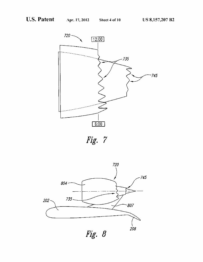
FIG. 7 illustrates a nozzle 720 having first or fan flow reduce jet-flap interaction noise, and also longer toward theprojections 735 and second or core flow projections 745. The
fuselage to reduce cabin noise. The projections may be
fan flow projections 735 and the core flow projections 745
shorter toward the bottom of the nozzle and toward the side ofvary in monotonic, opposite manners. That is, the fan flow 25 the nozzle away from the fuselage, so as not to significantlyprojections 735 tend to be longer toward the bottom of the
impact the overall exhaust product mass flow and thrust level,
nozzle 720 than toward the top of the nozzle 720, while the
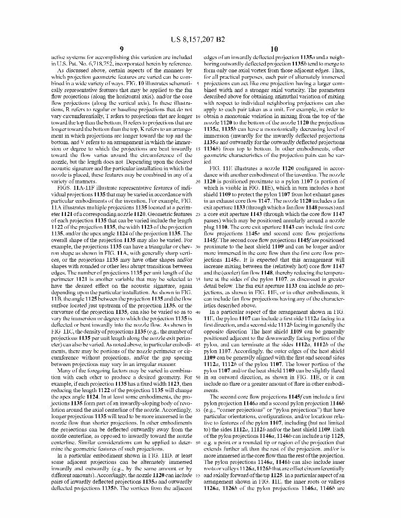
in a region of the nozzle where reduced acoustic signaturecore flow projections 745 vary in the opposite manner. The may not be as important as it is near the fuselage and near thevariation of the fan flow projections 735 is the opposite of the wing.arrangement of fan flow projections 235 shown in FIG. 3. so FIG. 9C schematically illustrates a nacelle 904c and nozzleAccordingly, this arrangement may be suitable when the
920 having projections configured to meet multiple acousticnozzle 720 is carried by a pylon extending downwardly objectives in the manner described above. In particular,(rather than upwardly) from the engine. Such an arrangement
longer projections 935c toward the top of the nozzle 920 are
is shown in FIG. 8. In particular, FIG. 8 illustrates the wing positioned to reduce jet-mixing noise (e.g., due to an over-202 with an upper surface mounted pylon 807 carrying a 35 head wing and/or pylon), as represented by a first acousticnacelle 804 housing the nozzle 720. In this arrangement, the radiation vector Al. Longer projections 935d toward thetrailing edge devices 208 deploy downwardly (in a typical
inboard side of the nozzle 920 are positioned to reduce shock-
fashion) and, therefore, may not contribute significantly to the cell noise, as represented by a second acoustic vector A2.jet-flap interaction noise described above. However, the
FIG. 9D schematically illustrates a nozzle 920 configured
downstream wake of the pylon 807 may interact with the 40 in accordance with another embodiment of the invention toexhaust products and accordingly, it may be advantageous to
include two types of azimuthally varying projections: fan
have the fan flow projections 735 be longer in a region adja- flow projections 935d that are longer and/or more immersedcent to the pylon 807, than in a region distant from the pylon toward the top of the nozzle (near the pylon), and core flow807. projection 945dhaving monotonically decreasing lengths in a
FIG. 9A illustrates an aircraft 900 having two engine 45 direction away from the fuselage 901. It is expected that thisnacelles 904a, 904b that depend from or are at least proximate arrangement can reduce both community noise at low fre-to the fuselage 901. In this particular embodiment, each of the quencies and shockcell/cabin noise at higher frequencies.engine nacelles 904a, 904b is carried by the fuselage 901 via
In still further embodiments, the manner in which the pro-
a corresponding pylon 907. The nacelles 904a, 904b can
jections vary around the nozzle perimeter (and therefore theinclude fan flow projections 935a, 935b that are configured to 5o degree of mixing between the adjacent flows) can be changedreduce the noise transmitted to the interior of the fuselage 901
depending on flight regime of the aircraft, by changing the
(e.g., the passenger compartment). In particular, the fan flow
degree to which the projections are immersed as a function ofprojections 935a, 935b can be longer at a position close to the time. This arrangement canbe used to reduce different spectrafuselage 901 than they are in a position distant from the of noise in different flight regimes. For example, to obtainfuselage 901. As a result, the fan flow projections 935a on the 55 more mixing between the fan flow and the freestream air nearleft nacelle 904a tend to be longest near the 3:00 position, and
the pylon (e.g., to reduce low-frequency noise during take-
shortest near the 9:00 position, while the fan flow projections off), the projections near the pylon can be actively bent935b on the second nacelle 904b have the opposite arrange- inwardly during takeoff. If mid-frequency shockcell noise atment. It is expected that the enhanced mixing provided by the cruise is reducedby another type of azimuthal variation, (e.g.,longer fan flow projections 935a, 935b near the fuselage 901 6o by immersing projections near the fuselage by a greater(which may have relatively greater immersion into the flow)
amount than projections away from the fuselage), then this
can reduce the acoustic signature close to the fuselage 901, change canbe made during the appropriate flightregime (e.g.,and can accordingly reduce the sound level experienced by
during cruise). Such desired azimuthal variations in projec-
passengers within the passenger compartment. The fan flow tion immersions can be obtained, for example, by using shapeprojections 935a, 935b that are more distant from the fuselage 65 memory alloys inside the projections and suitable heat con-901 can be shorter so as to reduce the overall effect of the fan trol elements. This arrangement can be applied to fan flowflow projections 935a, 935b on engine thrust. FIG. 9B illus- projections, and/or core flow projections. Further aspects of
US 8,157,207 B29
10active systems for accomplishing this variation are included
edges of an inwardly deflected projection 1135a and a neigh-
in U.S. Pat. No. 6,718,752, incorporated herein by reference. boring outwardly deflected projection 1135b tend to merge toAs discussed above, certain aspects of the manners by
form only one axial vortex from those adjacent edges. Thus,
which projection geometric features are varied can be com- for all practical purposes, each pair of alternately immersedbined in a wide variety of ways. FIG. 10 illustrates schemati- 5 projections can act like one projection having a larger com-cally representative features that may be applied to the fan
bined width and a stronger axial vorticity. The parameters
flow projections (along the horizontal axis), and/or the core
described above for obtaining azimuthal variation of mixingflow projections (along the vertical axis). In these illustra- with respect to individual neighboring projections can alsotions, R refers to regular or baseline projections that do not apply to each pair taken as a unit. For example, in order tovary circumferentially, T refers to projections that are longer io obtain a monotonic variation in mixing from the top of thetoward the top than the bottom, B refers to projections that are nozzle 1120 to the bottom of the nozzle 1120 the projectionslonger toward the bottom than the top, K refers to an arrange- 1135a, 1135b can have a monotonically decreasing level ofment in which projections are longer toward the top and the
immersion (inwardly for the inwardly deflected projections
bottom, and V refers to an arrangement in which the immer- 1135a and outwardly for the outwardly deflected projectionssion or degree to which the projections are bent inwardly 15 1136b) from top to bottom. In other embodiments, othertoward the flow varies around the circumference of the geometric characteristics of the projection pairs can be var-nozzle, but the length does not. Depending upon the desired
ied.
acoustic signature and the particular installation in which the
FIG. 11E illustrates a nozzle 1120 configured in accor-nozzle is placed, these features may be combined in any of a
dance with another embodiment of the invention. The nozzle
variety of manners. 20 1120 is positioned proximate to a pylon 1107 (a portion ofFIGS. 11A-11F illustrate representative features of indi- which is visible in FIG. 11E), which in turn includes a heat
vidual projections 1135 that maybe varied in accordance with
shield 1109 to protect the pylon 1107 from hot exhaust gasesparticular embodiments of the invention. For example, FIG. in an exhaust core flow 1147. The nozzle 1120 includes a fan11A illustrates multiple projections 1135 located at a perim- exit aperture 1133 (through which a fan flow 1148 passes) andeter 1121 of a corresponding nozzle 1120. Geometric features 25 a core exit aperture 1143 (through which the core flow 1147of each projection 1135 that can be varied include the length
passes) which may be positioned annularly around a nozzle
1122 of the projection 1135, the width 1123 of the projection plug 1110. The core exit aperture 1143 can include first core1135, and/or the apex angle 1124 of the projection 1135. The
flow projections 1145e and second core flow projections
overall shape of the projection 1135 may also be varied. For
1145f. The second core flow projections 1145f are positionedexample, the projections 1135 can have a triangular or chev- 30 proximate to the heat shield 1109 and can be longer and/orron shape as shown in FIG. 11A, with generally sharp verti- more immersed in the core flow than the first core flow pro-ces, or the projections 1135 may have other shapes and/or
jections 1145e. It is expected that this arrangement will
shapes with rounded or other less abrupt transitions between
increase mixing between the (relatively hot) core flow 1147edges. The number of projections 1135 per unit length of the and the (cooler) fan flow 1148, thereby reducing the tempera-perimeter 1121 is another variable that may be selected to 35 ture at the sides of the pylon 1107, as discussed in greaterhave the desired effect on the acoustic signature, again
detail below. The fan exit aperture 1133 can include no pro-
depending upon the particular installation. As shown in FIG. jections, as shown in FIG. 11E, or in other embodiments, it1113, the angle 1125 between the projection 1135 and the flow can include fan flow projections having any of the character-surface located just upstream of the projection 1135, or the
istics described above.
curvature of the projection 1135, can also be varied so as to 40 In a particular aspect of the arrangement shown in FIG.vary the immersion or degree to which the projection 1135 is
11E, the pylon 1107 can include a first side 1112a facing in a
deflected or bent inwardly into the nozzle flow. As shown in
first direction, and a second side 1112b facing in generally theFIG. 11C, the density of projections 1135 (e.g., the number of
opposite direction. The heat shield 1109 can be generally
projections 1135 per unit length along the nozzle exit perim- positioned adjacent to the downwardly facing portion of theeter) can also be varied. As noted above, in particular embodi- 45 pylon, and can terminate at the sides 1112a, 1112b of thements, there may be portions of the nozzle perimeter or cir- pylon 1107. Accordingly, the outer edges of the heat shieldcumference without projections, and/or the gap spacing
1109 can be generally aligned with the first and second sides
between projections may vary in an irregular manner. 1112a, 1112b of the pylon 1107. The lower portion of theMany of the foregoing factors may be varied in combina- pylon 1107 and/or the heat shield 1109 can be slightly flared
tion with each other to produce a desired geometry. For 50 in an outward direction, as shown in FIG. 11E, or it canexample, if each projection 1135 has a fixed width 1123, then
include no flare or a greater amount of flare in other embodi-
reducing the length 1122 of the projection 1135 will change ments.the apex angle 1124. In at least some embodiments, the pro- The second core flow projections 1145f can include a firstjections 1135 form part of an inwardly-sloping body of revo- pylon projection 1146a and a second pylon projection 1146blution around the axial centerline of the nozzle. Accordingly, 55 (e.g., "corner projections" or "pylon projections") that havelonger projections 1135 will tend to be more immersed in the particular orientations, configurations, and/or locations rela-nozzle flow than shorter projections. In other embodiments tive to features of the pylon 1107, including (but not limitedthe projections can be deflected outwardly away from the to) the sides 1112a, 1112b and/or the heat shield 1109. Eachnozzle centerline, as opposed to inwardly toward the nozzle of the pylon projections 1146a, 1146b can include a tip 1125,centerline. Similar considerations can be applied to deter- 60 e.g. a point or a rounded tip or region of the projection thatmine the geometric features of such projections. extends further aft than the rest of the projection, and/or is
In a particular embodiment shown in FIG. 11D, at least more immersed in the core flow than the rest of the projection.some adjacent projections can be alternately immersed
The pylon projections 1146a, 1146b can also include inner
inwardly and outwardly (e.g., by the same amount or by roots or valleys 1126a, 1126bthat are offset circumferentiallydifferent amounts). Accordingly, the nozzle 1120 can include 65 and axially forward of the tip 1125. Ina particular aspect of anpairs of inwardly deflected projections 1135a and outwardly arrangement shown in FIG. 11E, the inner roots or valleysdeflected projections 1135b. The vortices from the adjacent
1126a, 1126b of the pylon projections 1146a, 1146b are
US 8,157,207 B211
generally aligned circumferentially with the edges of the heatshield 1109 and/or the first and second sides 1112a, 1112b,respectively, of the pylon 1107. Accordingly, the correspond-ing tips 1125 of the pylon projections 1146a, 1146b are offsetoutwardly in opposite directions away from the first side1112a and the second side 1112b, respectively, as indicatedby dashed lines and arrows C in FIG. 11E. As discussedabove, it is expected that in at least some arrangements, theincreased immersion of the pylon projections 1146a, 1146bin the core flow, compared with the first core flow projections1145e, can enhance vorticity and mixing with fan flow air inthe region of the pylon 1107 and the heat shield 1109, and canaccordingly reduce the degree to which one or both of thesecomponents are exposed to the high temperature core flowgases.
In other arrangements, the pylon projections 1146a, 1146bcan have other configurations and/or locations relative to thepylon 1107. For example, referring now to FIG. 11F, the firstand second pylon projections 1146a, 1146b each include a tip1125 that is generally aligned circumferentially with the cor-responding pylon sides 1112a, 1112b, and/or the edges of theheat shield 1109. Accordingly, outer valleys or roots 1127a, bof the pylon projections 1146a, 1146b can be offset outwardlyfrom the pylon sides 1112a, 1112b. It is expected that in atleast some embodiments (e.g., when the heat shield 1109 isunflared, as shown in FIG. 11F), this arrangement can furtherreduce the exposure of components of the pylon 1107 to hightemperatures because hot core flow components 1150a,1150b can escape radially outwardly from the outer valleys1127a, b, respectively, and are located circumferentiallyaway from the pylon sides 1112a, 1112b as indicated byarrows D. Accordingly, this arrangement can further reducethe likelihood for hot core flow to scorch or otherwise heat thepylon sides 1112a, 1112b. The positions of the tips 1125and/ortheroots 1126a, 1126b, 1127a, 1127b can be identifiedby distance (e.g., an arc length), an angle (e.g., relative to a12:00 position), or other suitable measures.
In a particular aspect of an arrangement shown in FIG. 11F,the pylon projections 1146a, 1146b can be individually asym-metric. That is, each of the projections 1146a, 1146b can havea greater circumferential extent in one direction from the tip1125 than in the other. For example, the second pylon projec-tion 1146b can extend inwardly toward the pylon 1107 by ashorter distance than it extends outwardly away from thepylon 1107. In other embodiments, the pylon projections1146a, 1146b can be asymmetric in other manners, e.g.extending inwardly toward the pylon 1107 by a greater dis-tance than they extend outwardly away from the pylon 1107,or they can be generally symmetric, as shown in FIG. 11E.The degree of symmetry or asymmetry can be selected basedon the configuration of the pylon 1107 and/or the heat shield1109. In general, the first and second pylon projections1146a, 1146b can be mirror images of each other, e.g.reflected about a plane that passes vertically through thecenter of the nozzle 1120. In other arrangements, the pylonprojections 1146a, 1146b can be asymmetric relative to eachother, again depending upon the particular features of thepylon 1107 and/ortheheat shield 1109. The pylon projections1146a, 1146b can be axially aligned with the flow direction ofthe core exhaust, or they can have other orientations (e.g.,twisted shapes) that can, in at least some instances, furtherenhance fan flow entrainment. The remaining projections(e.g. the first core flow projections 1145e) can have geometricfeatures that change in a generally monotonic manner aroundat least a portion of the nozzle perimeter, in any of the man-ners described herein.
12As discussed above, an advantage of pylon projections
1146a, 1146b having any one or combination of the featuresdescribed above is that they can reduce the exposure of thepylon sides 1112a, 1112b and/or the heat shield 1109 to heat
5 from the exhaust core flow, while the remaining projectionsproduce enhanced noise reduction. In particular embodi-ments, this effect can be achieved by entraining additionalby-pass air from the adjacent by-pass air flow path, and/or byincreasing vorticity in the region adjacent to the pylon 1107.
to This effect can be of increased importance during cross-windconditions, when the hot core flow exhaust may have anincreased effect in a lateral direction, and hence an increasedeffect on the pylon 1107.
15 In a particular embodiment, the foregoing characteristicscan be used to configure the pylon projections 1146a, 1146band the heat shield 1109 in an interdependent manner. Forexample, the pylon chevrons 1146a, 1146b can be selected tohave a particular configuration (e.g. location, position, and/or
20 geometry), and the heat shield 1109 can be configured toprovide sufficient heat protection to the pylon 1107 in light ofthe expected flow characteristics produced by the pylon pro-jections 1146a, 1146b. The configurations of both elementscan then be adjusted in an interdependent manner to produce
25 a design that results in both adequate heat protection for thepylon 1107, and adequate sound attenuation for the overallflow produced by the nozzle 1120. The particular solutionselected as a result of the foregoing design method can also bechosen to produce the lowest weight configuration or can be
30 selected to emphasize other desirable characteristics. Anadvantage of thi s design methodology is that it recognizes andcan exploit the interdependency of these geometric features.
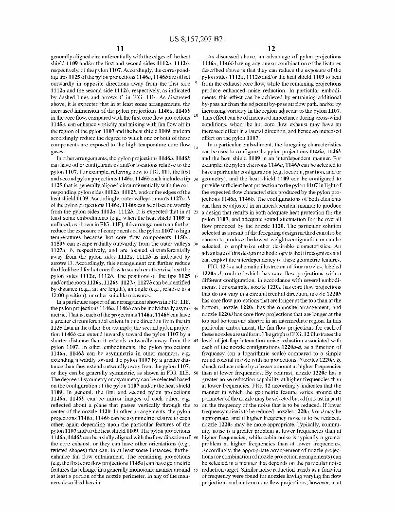
FIG. 12 is a schematic illustration of four nozzles, labeled35 1220a-d, each of which has core flow projections with a
different configuration, in accordance with several embodi-ments. For example, nozzle 1220a has core flow projectionsthat do not vary in a circumferential direction, nozzle 1220bhas core flow projections that are longer at the top than at the
40 bottom, nozzle 1220c has the opposite arrangement, andnozzle 1220d has core flow projections that are longer at thetop and bottom and shorter in an intermediate region. In thisparticular embodiment, the fan flow projections for each ofthese nozzles are uniform. The graph of FIG. 12 illustrates the
45 level of jet-flap interaction noise reduction associated witheach of the nozzle configurations 1220a-d, as a function offrequency (on a logarithmic scale) compared to a simpleround coaxial nozzle with no projections. Nozzles 1220a, b,d each reduce noise by a lesser amount at higher frequencies
50 than at lower frequencies. By contrast, nozzle 1220c has agreater noise reduction capability at higher frequencies thanat lower frequencies. FIG. 12 accordingly indicates that themanner in which the geometric feature varies around theperimeter of the nozzle may be selected based (at least in part)
55 on the frequency of the noise that is to be reduced. If lowerfrequency noise is to bereduced, nozzles 1220a, b or d may beappropriate, and if higher frequency noise is to be reduced,nozzle 1220c may be more appropriate. Typically, commu-nity noise is a greater problem at lower frequencies than at
6o higher frequencies, while cabin noise is typically a greaterproblem at higher frequencies than at lower frequencies.Accordingly, the appropriate arrangement of nozzle projec-tions (or combination of nozzle projection arrangements) canbe selected in a manner that depends on the particular noise
65 reduction target. Similar noise reduction trends as a functionof frequency were found for nozzles having varying fan flowprojections and uniform core flow projections; however, in at

US 8,157,207 B213
14least some of these cases, the reduction in the noise that is due
AIAA Paper 2001-2185, entitled "Computational Analysis of
to jet-flap interaction was higher than for the (baseline) nozzle a Pylon-Chevron Core Nozzle Interaction, dated May 28-30,1220a. 2001; AIAA Paper 2004-2827 entitled "Jet Pylon Interaction
FIGS. 13A-C and 14 illustrate still further geometric fea- of High Bypass Ratio Separate Flow Nozzle Configurations";tures that may be varied to achieve desired thrust and acoustic 5 AIAA Paper 2006-2467, entitled "Reducing Propulsion Air-signature results in accordance with further embodiments of
frame Aeroacoustic Interactions with Uniquely Tailored
the invention. In particular, FIGS. I3A-13C illustrate nozzles
Chevrons: 1. Isolated Nozzles," dated May 8-10, 2006; AIAAhaving different root locus lines 1326 (shown as root locus
Paper 2006-2434, entitled "Reducing Propulsion Airframe
lines 1326a-1326c) and tip locus lines 1327 (shown as tip
Aeroacoustic Interactions with Uniquely Tailored Chevrons:locus lines 1327a-1327c). The root locus lines 1326a-1326b io 2. Installed Nozzles," dated May 8-10, 2006; AIAA Paperconnect the root locations of successive fan flow projections
2006-2435, entitled "Reducing Propulsion Airframe Aeroa-
1335, and the tip locus lines 1327a-1327c connect the tip coustic Interactions with Uniquely Tailored Chevrons: 3. Jet-locations of the same projections 1335. FIG. 13A illustrates a
Flap Interaction," dated May 8-10, 2006; AIAA Paper 2006-
generally vertical root locus line 1326a and an aft-canted tip
2439, entitled "Flight Test Results for Uniquely Tailoredlocus line 1327a. FIG. 13B illustrates a forwardly-canted root 15 Propulsion-Airframe Aeroacoustic Chevrons: Shockcelllocus line 1326b and a generally vertical tip locus line 1327b. Noise," dated May 8-10, 2006; AIAA Paper 2006-2438,FIG. 13C illustrates a forwardly-canted root locus line entitled "Flight Test Results for Uniquely Tailored Propul-1326C, an aft-canted tip locus line 1327c, and a generally sion-Airframe Aeroacoustic Chevrons: Community Noise,"vertical centroid locus line 1328c. The appropriate orienta- dated May 8-10, 2006; AIAA Paper 2006-2436, entitledtion of the root and tip locus lines may be selected to produce 20 "Computational Analysis of a Chevron Nozzle Uniquely Tai-the desired acoustic vector, thrust vector, and/or other appro- lored for Propulsion Airframe Aeroacoustics," dated Maypriate parameter. For example, canting the root locus line
8-10, 2006; AIAA Paper 2005-0996, entitled "Relative
1326 and/or the tip locus line 1327 may cant the thrust vector. Clocking of Enhanced Mixing Devices for Jet Noise Benefit,"If a particular azimuthal arrangement of projections 1335
dated Jan. 10-13, 2005; AIAA Paper 2005-2934, entitled "Jet
shifts the thrust vector in an undesirable manner, canting the 25 Noise Characteristics of Chevrons in Internally Mixedroot locus line 1326 and/or the tip locus line 1327 can be used
Nozzles," dated May 23-25, 2005; and AIAA Paper 2006-
to correct the thrust vector back to the desired orientation. 0623, entitled "Internal Flow and Noise of Chevrons andThis methodology is illustrated in the context of fan flow
Lobe Mixers in Mixed-Flow Nozzles," dated Jan. 9-12, 2006.
projections, but may be applied to core flow projections in
Aspects of the disclosure described in the context of par-addition to or in lieu of the fan flow projections. 30 ticular embodiments may be combined or eliminated in other
FIG. 14 illustrates the "rolling ball" flow area through the embodiments. For example, many of the geometric featuresfan flow duct of a nozzle configured in accordance with
described individually above may be combined in any of a
another embodiment of the invention. FIG. 14 illustrates that variety of manners to meet corresponding acoustic and thrustthe nozzle has a locally convergent-divergent arrangement, design goals, while integrating appropriately with other struc-with a geometric throat T upstream of a corresponding root 35 tures of the aircraft into which the nozzles are integrated.locus line 1426. This arrangement is expected to have several
Further, while advantages associated with certain embodi-
beneficial effects. For example, a local convergent-divergent ments of the disclosure have been described in the context ofregion of the nozzle is expected to have enhanced aerody- those embodiments, other embodiments may also exhibitnamic effects at particular flight regimes. By positioning the such advantages, and not all embodiments need necessarilygeometric throat T upstream of the root locus line 1426, the 40 exhibit such advantages to fall within the scope of the disclo-effective exit area of the nozzle can be controlled such that it sure.does not become susceptible to fan instability problems at low
We claim:
nozzle pressure ratios of the fan stream. The latter can occur
1. An aircraft system, comprising:when using inwardly immersed fan flow projections which
a pylon having a first side, a second side facing opposite the
can aerodynamically effectively behave like convergent 45 first side, and a heat shield having a first edge proximatenozzles. The shape of the projections that controls the local
to the first side of the pylon and a second edge proximate
convergent-divergent behavior of the rolling ball area can be to the second side of the pylon; andused to control the effective exit area and avoid fan instabili- a jet engine exhaust nozzle carried by the pylon and havingties. It is expected that this arrangement can reduce thrust an internal flow surface adjacent a hot exhaust flow path,degradation. It will be understood that in at least some cases, 50 the internal flow surface having an exit aperture with athe nozzle can include an aerodynamic convergent section perimeter that includes multiple projections extendingdownstream of the local convergent-divergent region dis- in an aft direction and circumferentially spaced aboutcussed above. the perimeter, with a geometric feature of the multiple
From the foregoing, it will be appreciated that specific projections changing in a monotonic manner along atembodiments of the invention have been described herein for 55 least a portion of the perimeter, wherein a first projectionpurposes of illustration, but that various modifications may be nearest the first side of the pylon and a second projectionmade without deviating from the invention. For example, nearest the second side of the pylon are both orientedseveral of the embodiments described above were described
inwardly into the flow path by a greater amount than the
in the context of nozzles having core flow paths that extend
remaining projections, and wherein at least a portion ofaxially further aft than the corresponding fan flow paths (e.g., 60 the first projection is positioned circumferentially out-externally mixed nozzles). In other embodiments, the nozzles wardly from the first edge of the heat shield and at leastmay be internally mixed and may have fan flow paths that a portion of the second projection is positioned circum-extend further aft than the corresponding core flow paths. The
ferentially outwardly from the second edge of the heat
nozzles may have a variety of exit perimeter shapes, including shield.round, rectangular and elliptical. 65 2. The system of claim 1 wherein at least a portion of the
Still further embodiments are described in the following
first projection is positioned circumferentially outwardlydocuments, all of which are incorporated herein by reference:
from the first side of the pylon and at least a portion of the
US 8,157,207 B215
second projection is positioned circumferentially outwardlyfrom the second side of the pylon.
3. The system of claim 1 wherein:each of the first and second projections has a generally
triangular shape with a root and a tip;the root of the first projection has a first orientation relative
to the first side of the pylon; andthe root of the second projection has a second orientation
relative to the second side of the pylon that generallymirrors the first orientation.
4. The system of claim 3 wherein the root of the firstprojection is offset from the first side of the pylon by a firstvalue in a first direction, and wherein the root of the secondprojection is offset from the second side of the pylon by asecond value generally the same as the first value in a seconddirection generally opposite the first direction.
5. The system of claim 4 wherein the root of the firstprojection is offset from the first side of the pylon by a firstangle in a first direction, and wherein the root of the secondprojection is offset from the second side of the pylon by asecond angle generally the same as the first angle in a seconddirection generally opposite the first direction.
6. The system of claim 4 wherein the root of the firstprojection is offset from the first side of the pylon by a firstdistance in a first direction, and wherein the root of the secondprojection is offset from the second side of the pylon by asecond distance generally the same as the first distance in asecond direction generally opposite the first direction.
7. The system of claim 3 wherein the tip of the first projec-tion is offset from the first side of the pylon by a first value ina first direction, and wherein the tip of the second projectionis offset from the second side of the pylon by a second valuegenerally the same as the first value in a second directiongenerally opposite the first direction.
8. The system of claim 3 wherein the tip of the first projec-tion is circumferentially aligned with the first side of thepylon and wherein the tip of the second projection is circum-ferentially aligned with the second side of the pylon.
9. The system of claim 1 wherein the first projection isinclined radially inwardly into the flow by a greater amountthan is a neighboring projection located circumferentiallyoutwardly from the first projection.
10. The system of claim 1 wherein the first projection hasa greater axial extent than does a neighboring projectionlocated circumferentially outwardly from the first projection.
11. The system of claim 1 wherein the exhaust nozzleincludes a fan flow path positioned radially outwardly fromthe internal flow surface.
12.A method for operating an aircraft engine, comprising:directing a flow of hot exhaust gas from an aircraft engine
through an exhaust nozzle exit aperture, the aperturehaving a perimeter with axially extending projectionsarranged around the perimeter, and with a geometricfeature of the projections changing in a monotonic man-ner along at least a portion of the perimeter; and
controlling the flow of hot exhaust gas near a pylon sup-porting the engine by directing the flow adjacent to firstand second projections located at least partially out-wardly from and nearest to first and second oppositelyfacing sides of the pylon, the first and second projectionsbeing oriented inwardly into the flow by a greateramount than are the remaining projections, wherein thepylon includes a heat shield having a first edge proxi-mate to the first side of the pylon and a second edgeproximate to the second side of the pylon, and wherein atleast a portion of the first projection is positioned cir-cumferentially outwardly from the first edge of the heatshield and at least a portion of the second projection ispositioned circumferentially outwardly from the secondedge of the heat shield.
1613. The method of claim 12 wherein controlling the flow
includes at least restricting the hot flow from passing adjacentto at least one of the sides of the pylon.
14. The method of claim 12 wherein controlling the flow5 includes entraining air from an adjacent flow of coolerbypass
air by at a greater rate near the pylon than at other circumfer-ential locations around the nozzle exit aperture.
15. The method of claim 12 wherein each of the first andsecond projections has a generally triangular shape with a tip
i o and an inner and outer root, and wherein directing the hot flowincludes directing the flow adjacent to the outer root of thefirst projection that is located circumferentially outwardlyfrom the first side of the pylon, and directing the flow adjacentto the outer root of the second projection that is located
15 circumferentially outwardly from the second side of thepylon.
16. The method of claim 12 wherein controlling the flowincludes increasing an axial vorticity component of the flownear the pylon or the heat shield compared with an axial
20 vorticity component of the flow at other circumferential loca-tions around the exit aperture.
17. The method of claim 12 wherein controlling the flowincludes controlling an amount of heating at the sides of thepylon.
2518. A method for designing an aircraft system, comprising:sizing an engine pylon for carrying an aircraft engine and
exhaust nozzle having a hot exhaust flow path;configuring a set of multiple projections extending aft
around an exit aperture of the nozzle to have a geometricfeature that changes in a monotonic manner along at
30 least a portion of a perimeter of the exit aperture, theprojections including a first projection positioned near-est a first side of the pylon and a second projectionpositioned nearest a second side of the pylon facinggenerally opposite the first side; and
35 configuring a heat shield positioned to protect the pylonfrom exhaust gases, wherein configuring at least one ofthe heat shield and the set of projections is based at leastin part on expected results of configuring the other of theheat shield and the set of projections, and wherein con-
40 figuring at least one of the heat shield and the set ofprojections includes configuring at least a portion of thefirst projection to be circumferentially outwardly from afirst edge of the heat shield positioned proximate to thefirst side of the pylon, and at least a portion of the secondprojection to be circumferentially outwardly from a sec-
45 and edge of the heat shield positioned proximate to thefirst side of the pylon.
19. The method of claim 18 wherein configuring multipleprojections includes configuring the first and second projec-tions to be immersed in the exhaust flow path to a greater
50 degree than the remaining projections.20. The method of claim 19 wherein configuring the first
and second projections includes configuring the first and sec-ond projections to be angled inwardly into the flow path by agreater degree than the remaining projections.
55 21. The method of claim 18 wherein each of the first andsecond projections includes a tip and a root, and whereinconfiguring the heat shield includes aligning edges of the heatshield to be offset inwardly from the tips of the first andsecond projections.
60 22. The method of claim 18 wherein each of the first andsecond projections includes a tip and a root, and whereinconfiguring the heat shield includes aligning edges of the heatshield to be circumferentially aligned with the tips of the firstand second projections.
65