mu uuuu ui iiui imi uui um uui uui uui mu mui uu uii mi - nasa · pdf filemu uuuu ui iiui imi...
TRANSCRIPT
mu uuuu ui iiui imi uui um uui uui uui mu mui uu uii mi (12) United States Patent
Garverick et al.
(54) SYSTEM AND CIRCUITRY TO PROVIDE STABLE TRANSCONDUCTANCE FOR BIASING
(75) Inventors: Steven L. Garverick, Solon, OH (US); Xinyu Yu, San Jose, CA (US)
(73) Assignee: Case Western Reserve University, Cleveland, OH (US)
(*) Notice: Subject to any disclaimer, the term of this patent is extended or adjusted under 35 U.S.C. 154(b) by 832 days.
(21) Appl. No.: 12/407,348
(22) Filed: Mar. 19, 2009
(65)
Prior Publication Data
US 2009/0205436 Al Aug. 20, 2009
Related U.S. Application Data
(63) Continuation-in-part of application No. 11/537,488, filed on Sep. 29, 2006, now Pat. No. 7,562,581.
(60) Provisional application No. 60/721,649, filed on Sep. 29, 2005.
(51) Int. Cl. HOIL 35100 (2006.01) G05F 11625 (2006.01) G05F 3126 (2006.01)
(52) U.S. Cl . ........................................ 327/513; 327/538 (58) Field of Classification Search .................. 341/143;
327/513,538 See application file for complete search history.
(56)
References Cited
U.S. PATENT DOCUMENTS
6,484,818 B2 11/2002 Alft et al.
6,700,445 B2 3/2004 Venkatraman et al.
(1o) Patent No.: US 8,299,844 B2 (45) Date of Patent: Oct. 30, 2012
OTHER PUBLICATIONS
Green, J.A. et al., "Single-chip surface micromachines integrated
gyroscope with 50/h Allan deviation," Solid-State Circuits, IEEE Journal of, vol. 37, No. 12, pp. 1860-1866, Dec. 2002. McLaren A. et al., "Generation of accurate on-chip time constants and stable transconductances," Solid-State circuits, IEEE Journal of, vol. 36, No. 4, pp. 691-695, Apr. 2001. Nicolson, S. et al. "Improvements in biasing and compensation of CMOS opamps," Circuits and Systems, 2004. ISCAS '04. Proceed-ings of the 2004 International Symposium on, pp. I-665-8 vol. 1, May 23-26,2004. B. Razavi, Design ofAnalog CMOS Integrated Circuits, pp. 378-379 and 393-393, Mcgraw-Hill Book Company, 2001. Toygur, L. Ph.D Thesis, Case Western Reserve University, Jan. 2004. Toygur, L. Ph.D. Thesis, Case Western Reserve University, Jan. 2004. Online date Jun. 2004 on ProQuest. Toygur, L. et al., "High-Temperature, Low-Power 8-MegQ by 1.2-MegHz SOI-CMOS Transimpedance Amplifier for MEMS-Based Wireless Sensors." IEEE International SOI Conference. pp. 179-181. Oct. 2004.
Primary Examiner Lisa Caputo Assistant Examiner Punam Roy (74) Attorney, Agent, or Firm Tarolli, Sundheim, Covell & Tummino LLP
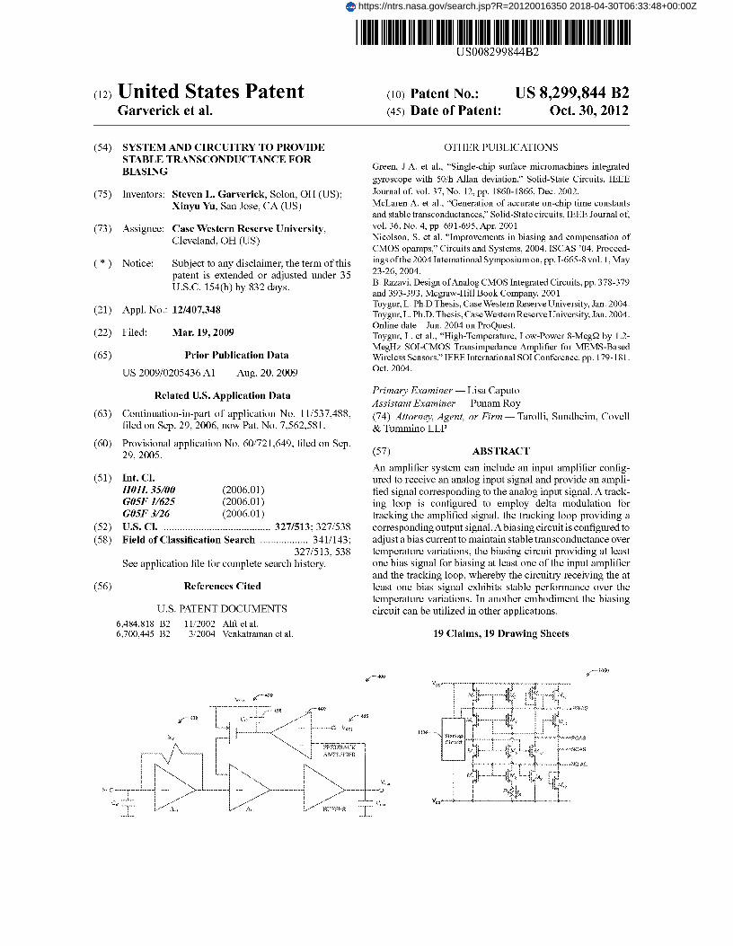
(57) ABSTRACT
An amplifier system can include an input amplifier config-ured to receive an analog input signal and provide an ampli-fied signal corresponding to the analog input signal. A track-ing loop is configured to employ delta modulation for tracking the amplified signal, the tracking loop providing a corresponding output signal. A biasing circuit is configured to adjust a bias current to maintain stable transconductance over temperature variations, the biasing circuit providing at least one bias signal for biasing at least one of the input amplifier and the tracking loop, whereby the circuitry receiving the at least one bias signal exhibits stable performance over the temperature variations. In another embodiment the biasing circuit can be utilized in other applications.
19 Claims, 19 Drawing Sheets
`- 4W
u.— 430 P
-61b T..
r v_
i1 \\\ 1' AEf.1ZtACK
1 1 1 \
ti
https://ntrs.nasa.gov/search.jsp?R=20120016350 2018-04-30T06:33:48+00:00Z

U.S. Patent Oct. 30, 2012 Sheet 1 of 19 US 8,299,844 B2
llq
<; z z
~s
E
f

vt 1114
U.S. Patent Oct. 30, 2012 Sheet 2 of 19
US 8,299,844 B2
n.

U.S. Patent Oct. 30, 2012 Sheet 3 of 19 US 8,299,844 B2
I vr

U.S. Patent Oct. 30, 2012 Sheet 4 of 19 US 8,299,844 B2
e•:
J

U.S. Patent Oct. 30, 2012 Sheet 5 of 19 US 8 ,299,844 B2
~ s s
al
eta . ,r,. ~-` w {""_•:
H. ....................
i
'r r a f
............ . .. f......... . >~
a
Y a
, ................... :................. > .<
.....................; 2
----------------------------- --
.............. ........... ..
..............
----------------
s,
.° --- ---- ------- -------------- ----- . ..... ................
. ................ ...... ... ............ ...... ........
z
......................... ....... .................. I f ------------------------- --------
9

U.S. Patent Oct. 30, 2012 Sheet 6 of 19 US 8,299,844 B2

U.S. Patent Oct. 30, 2012 Sheet 7 of 19 US 8,299,844 B2
I 'IY
a,

L
kw
rT
IN
--------------------- -
j
\+ u
----------
-N
ne 2
CLI
7, Va
U.S. Patent Oct. 30, 2012 Sheet 8 of 19 US 8,299,844 B2

U.S. Patent Oct. 30, 2012 Sheet 9 of 19 US 8,299,844 B2
. . . . ....... . ... .... ... ... .... ... ...
. ...............
~ }
W6.
R

U.S. Patent Oct. 30, 2012 Sheet 10 of 19
US 8,299,844 B2
tr` a.I
gn
Ezr
< o-
l v..
m ~ ~ ups ~ ~ •> {
v.
15
V p 08 ~j' fAry vn....NS.~nruv
r

U.S. Patent Oct. 30, 2012 Sheet 11 of 19 US 8 ,299,844 B2
w~:: # a»we nvoca ,aawce ,. g
I
#
t, r,-' z
3
>f ; ~ Ci 1
§k~
•w
~
o.es
crs

~f
U.S. Patent Oct. 30, 2012 Sheet 12 of 19 US 8 ,299,844 B2
U.S. Patent Oct. 30, 2012 Sheet 13 of 19 US 8,299,844 B2
4 ------------ I ------------
- Cb
Lu In
U-1

~2"a
U.S. Patent Oct. 30, 2012
Sheet 14 of 19 US 8,299,844 B2

W I
IX
h^
w.R
x~ee~
F15 f :.3 <
1 a
~ x ~
:ate
cry
Ell
if3 max.
Y
(c ry ma
eq
U.S. Patent Oct. 30, 2012 Sheet 15 of 19
US 8,299,844 B2

U.S. Patent Oct. 30, 2012 Sheet 16 of 19 US 8,299,844 B2
aJ
C

U.S. Patent Oct. 30, 2012 Sheet 17 of 19 US 8,299,844 B2
!ets;
4:w
t
9
i+

U.S. Patent Oct. 30, 2012 Sheet 18 of 19 US 8 ,299,844 B2
mi k~ Ct
x:
U.R. Patent Oct. 30, 2012 Sheet 19 of 19 US 8,299,844 G2
Ff i xt
~ > / !
~ r » ~ _
\ ) ~ ~ \ / 6 ,
~ ..
CI d)
\\

US 8,299,844 B2 1
SYSTEM AND CIRCUITRY TO PROVIDE STABLE TRANSCONDUCTANCE FOR
BIASING
CROSS-REFERENCE TO RELATED APPLICATIONS
This application is a continuation-in-part of U.S. patent application Ser. No. 11/537,488, which was filed on Sep. 29, 2006 now U.S. Pat. No. 7,562,581 and entitled WIRELESS SENSOR PLATFORM FOR HARSH ENVIRONMENTS, and which claims the benefit of provisional patent application No. 60/721,649 filed Sep. 29, 2005, each of which prior applications is incorporated herein by reference in its entirety.
GOVERNMENT RIGHTS
This application is made with government support under NCA3-201 awarded by NASA—Glenn Research Center. The United States Government has certain rights in this invention.
BACKGROUND
Various applications, ranging from small to large, simple to complex, use sensors to monitor certain aspects of an envi-ronment. For instance, sensors can detect motion in a room to determine whether its ceiling lights should be turned on. Likewise, sensors can be applied to more complex applica-tions, including engine and vehicle control for automotive and aerospace systems, as well as environmental monitoring in mining, geothermal, and well logging. Accordingly, a wide variety of users (e.g., consumers, scientists, and engineers) regularly depend on the consistency and accuracy of sensor data collection and transmission. With the proliferation of technology in control systems, the importance of reliable monitoring and sensing platforms is apparent.
In particular, commercial, industrial, and military applica-tions rely on sensors to provide data relating to safety condi-tions, travel speeds, and warning signals. While a household or office environment may be fairly easy to monitor, an oper-ating automotive or aerospace system is considerably more difficult to work with. Complications that include tempera-ture, distance, and power considerations distort the signals that the sensors need to monitor. In general, sensors for com-mercial applications are rated for temperatures as high as 70° C., industrial applications at 85° C., and military applications at 125° C.
While slight distortions may not adversely impact the entire system, severe distortions may flag a false signal (or fail to flag an existing signal) which in turn can expose people to dangerous situations. When sensors fail to properly perform, the resulting effect may be at the least, inconvenient, and at the most, life threatening. For example, if a motion detecting sensor fails to signal the lights on in a room, a person in the room would merely be inconvenienced into walking over to the wall to manually flip the light switch on. Meanwhile, if an automobile brake sensor fails to activate the anti-lock braking system while the vehicle is traveling at high speeds, the car could spin out of control and put the driver and passengers (along with others in the vicinity) in severe danger.
SUMMARY
The following presents a simplified summary of the subj ect matter in order to provide a basic understanding of some aspects of subject matter embodiments. This summary is not an extensive overview of the subject matter. It is not intended
2 to identify key/critical elements of the embodiments or to delineate the scope of the subject matter. Its sole purpose is to present some concepts of the subject matter in a simplified form as a prelude to the more detailed description that is
5 presented later. One embodiment provides an amplifier system that
includes an input amplifier configured to receive an analog input signal and provide an amplified signal corresponding to the analog input signal. A tracking loop is configured to
10 employ delta modulation for tracking the amplified signal, the tracking loop providing a corresponding output signal. A biasing circuit is configured to adjust a bias current to main-tain stable transconductance over temperature variations, the biasing circuit providing at least one bias signal for biasing at
15 least one of the input amplifier and the tracking loop, whereby the circuitry receiving the at least one bias signal exhibits stable performance over the temperature variations.
Another embodiment of the invention provides a bias gen-erator for providing adaptive bias control that provides stabi-
20 lization of transconductance over temperature for associated circuitry. The bias generator includes a first arrangement of transistors that is configured as a first current mirror portion, the first current mirror portion being connected to a first reference voltage. A second arrangement of transistors and a
25 resistor is configured as a second current mirror portion hav-ing a non-linear characteristic to provide a bias current through the resistor that is inversely proportional to mobility. The first current mirror is connected with the second current mirror portion between the first voltage reference and a sec-
30 and voltage reference and being arranged in a feedback rela-tionship to stabilize the bias current through the resistor. A bias voltage is provided from at least one of the first current mirror portion and the second current mirror portion based on the bias current.
35 To the accomplishment of the foregoing and related ends, certain illustrative aspects of embodiments are described herein in connection with the following description and the annexed drawings. These aspects are indicative, however, of but a few of the various ways in which the principles of the
40 subject matter may be employed, and the subject matter is intended to include all such aspects and their equivalents. Other advantages and novel features of the subject matter may become apparent from the following detailed description when considered in conjunction with the drawings.
45
BRIEF DESCRIPTION OF THE DRAWINGS
FIG. 1 is a block diagram of a wireless sensor module. FIG. 2 is a block diagram of an integrated circuit used in a
50 wireless sensor module. FIG. 3 is a schematic block diagram of a wireless sensor
module. FIG. 4 is a schematic block diagram of a transimpedance
amplifier. 55 FIG. 5 is a transistor level circuit schematic of a transim-
pedance amplifier. FIG. 6 is a block diagram of a 1s t-order sigma-delta A/D
converter. FIG. 7 illustrates a discrete-time model of a I. sup. st-order
60 sigma-delta A/D converter. FIG. 8 is a schematic block diagram of a I.sup.st-order
sigma-delta A/D converter incorporating chopper stabiliza-tion, dynamic element matching, and input dither.
FIG. 9 is a circuit schematic of a digital FSK transmitter. 65 FIG. 10 is a schematic block diagram of a mixed-signal
instrumentation amplifier using delta modulation to obtain filtered analog output.
US 8,299,844 B2 3
4 FIG. 11A is a transistor level circuit schematic of a fully the amplifier provides a gain greater than 2 MQ and a band-
differential integrator with continuous-time output using just width greater than 0.3 MHz for temperatures up to 300° C.
one integration capacitor. The integrated circuit 120 also comprises anA/D converter FIG. 11B is a transistor level circuit schematic of a bias
220, such as an SOI-CMOS l.sup.st-order sigma-delta A/D circuit that enables temperature adaptive biasing. 5 converter, that converts the received analog input signal into
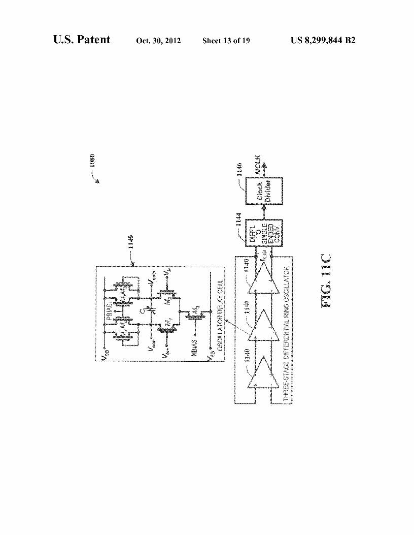
FIG. 11C is a schematic diagram of an oscillator that uses digital format. The SOI-CMOS 1s t-order sigma-delta A/D
temperature adaptive biasing to obtain stable oscillation fre- converter 220 is capable of high-temperature performance quency over wide temperature variations. with imprecise components using fully differential switched-
FIG. 11D is an example timing diagram of various clock capacitor circuits plus dynamic element matching, dithering,
phases provided by the clock generator of FIG. 10. io and chopper stabilization. The binary output of the compara- FIG. 12 is a schematic block diagram of an integrated
tor results in quantization error. However, the output tracks
circuit with double-sampled instrumentation amplifier and
the input and reduces the error by the oversampling ratio, and 2"d-order sigma-delta A/D converter. the signal proceeds through a low-pass decimation filter 230
FIG. 13A illustrates a discrete-time model of a 2 "d-order that removes the quantization error. Further included in the
sigma-delta modulator. 15 integrated circuit 120 is a digital transmitter (i.e., voltage- FIG. 13B is a schematic block diagram of a switched- controlled oscillator) 240. The digital FSK (frequency shift
capacitor integrator with finite-gain compensation. keying) transmitter 240 facilitates propagation through harsh FIG. 13C is an example timing diagram of various clock
environments through the selection of a relatively low carrier phases provided by the clock generator of FIG. 12. frequency and corresponding longer wavelength. A loop
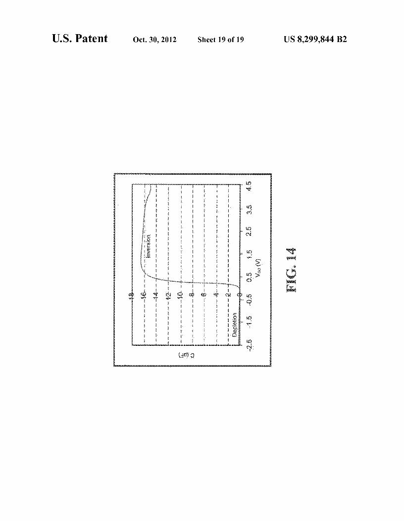
FIG. 14 is a graph depicting measured C-V characteristics 20 antenna (not shown) serves as an inductor and combines with of a transistor. the capacitance of a tunnel diode and PMOS varactor to form
a tank circuit. The wireless transmission of data can then be DETAILED DESCRIPTION
sent to a receiver for further evaluation orprocessing. Overall, the integrated circuit 120 facilitates the process of amplifying
The subject matter is now described with reference to the 25 an analog signal, converting the analog signal to digital form, drawings, wherein like reference numerals are used to refer to and filtering the digital signal to remove errors. like elements throughout. In the following description, for
The SOI-CMOS transimpedance amplifier 210 can serve a
purposes of explanation, numerous specific details are set
dual purpose: to acquire data from MEMS-based impedance forth in order to provide a thorough understanding of the sensors and to construct an oscillator using a MEMS resona- subject matter. It may be evident, however, that subj ect matter 30 tor. The amplifier 210 functions while maintaining a wide embodiments may be practiced without these specific details. gain-bandwidth at all temperatures (e.g., up to about 300° C.), In other instances, well-known structures and devices are sustaining low power consumption (e.g., under about 1 mW), shown in block diagram form in order to facilitate describing and utilizing a small die area (e.g., about 8500 µm 2 or less). the embodiments. The sigma-delta A/D converter 220 receives an amplified
In FIG. 1, a block diagram of a high-temperature, low 35 analog signal from the amplifier 210, converts the signal from power sensor module 100 that facilitates reliable sensing in analog to digital format, and sends a digitally converted signal harsh environments is illustrated. The sensor module 100
to the decimation filter 230. The A/D converter 220 achieves
comprises a sensor 110 that retrieves information from an a high SNR (signal to noise ratio) while drawing a low level of environment, an integrated circuit with digital transmitter 120
static power. In one example, at room temperature the A/D
that performs signal processing, including amplification, 40 converter 220 achieves an SNR above 50 dB while drawing conversion, and filtering, and an antenna 130 that communi- 1.32 mW from a 3.3 V power supply. In another example, at cates the resulting output signal to a receiver. The sensor 110
temperatures greater than 250° C., the A/D converter 220
receives an analog input signal to be processed by the inte- achieves an SNR above 40 dB while drawing less than 2 mW, grated circuit 120. The sensor may be resistive, capacitive, or also from a 3.3 V power supply. After the signal conversion, a combination of the two. Regardless of which type of sensor 45 the decimation filter 230 receives the digital signal from the is implemented, the AC admittance of the sensor can be
A/D converter 220 and proceeds by removing the quantiza-
recovered by the amplifier through conventional digital
tion error introduced by the A/D converter, through low-pass demodulation of the signal. More specifically, the integrated
filtering. The digital transmitter 240 is essentially a voltage-
circuit 120 amplifies the received analog signal, converts the controlled oscillator and wirelessly transmits the digital sig- signal into digital form, and filters the resulting digital signal. 5o nal via the loop antenna. Such signal is output by a digital transmitter as part of the
In FIG. 3, a schematic block diagram of a wireless sensor
integrated circuit 120 and antenna 130 so that it may be module 300 is presented. The sensor module 300 comprises a received wirelessly by a receiver. One advantage of wireless sensor 110 that collects information from an environment and implementation is the absence of tangled wires, especially for two instances of the transimpedance amplifier 210 (an oscil- rotating systems such as automotive wheels. Another advan- 55 lator 310 and a sensor interface amplifier 210) that provides tage is a less restricted range in distance from which the
for amplification. The wireless sensor module 300 also
module can operate. includes a sigma-delta A/D converter 220 that manages con- FIG. 2 depicts a block diagram of an integrated circuit 120
version of an analog signal to digital form and a decimation
that facilitates amplification, conversion, filtering, and trans- filter 230 that removes errors from the resulting digital signal. mitting of an input signal. The integrated circuit 120 com- 6o The wireless sensormodule also includes an FSK transmitter/ prises an amplifier 210, such as an SOI-CMOS transimped- voltage-controlled oscillator 240 that provides transmission ance amplifier, that amplifies the input signal. The SOI- assistance in harsh environments, and an antenna 130 that CMOS transimpedance amplifier 210 has a low input
broadcasts the signal transmission.
resistance suitable to receive data from MEMS-based high- First, the sensor 110 receives an analog signal. One impedance capacitive sensors. Such type of wide-gain-band- 65 instance of the amplifier 320 is used in conjunction with a width amplifier can also act as a stable oscillator by counter- MEMS resonator to construct the oscillator 310. The second acting the series resistance of a resonant device. As a result, instance of the amplifier 320 is used in a synchronous detec-
US 8,299,844 B2 5
6 tion scheme to measure sensor impedance 210. The amplifier
520, bias 530, voltage amplifier 540, push-pull buffer 550,
320 can be used to counteract the series resistance of a reso- feedback biasing amplifier 560, and bias 570. nant device to form a stable oscillator 310, through a design
The first (Ml-M3) 510 and second (M11-M14) 540 stages
that provides the gain and bandwidth necessary to construct employ cascoded common-source stages to improve voltage high-temperature high-Q integrated oscillators 310, such as 5 gain. A source-follower level-shifter (M6-M7) 520 is inserted by using SiC MEMS lateral and vertical resonators having
between the first 510 and second 540 stages in order to mini-
motional resistance (or equivalent series resistance at natural
mize capacitance loading on the first stage 510 and to estab- resonance thereof) that is over 1 MQ and resonant frequen- lish the necessary bias voltage for the second stage 540 input. cies as high as 1 MHz. The sensor interface amplifier 210 is
The output resistance of the first stage 510 is dominated by
able to acquire data from high-impedance sensors (e.g., 10 the output resistance of Ml, r. 1 , since the resistance due to the MEMS capacitive sensors) and can recover the AC admit- M2-M3 cascode is much larger. Therefore, A„ 1 is approxi- tance of the sensor 110 via synchronous demodulation with
mately 9m3ro1 , which is proportional to Ll, the channel length
in-phase and/or a quadrature reference signal, regardless of
of ML Ll is made relatively large to obtain high voltage gain, whether the sensor is resistive, capacitive, or a combination. but is limited by the need to obtain a resistance that is low
The analog signal is then converted into digital form by the 15 enough to obtain a satisfactory non-dominant pole frequency A/D converter 220 and filtered by a low pass decimation filter
in the first stage 510 feedback loop.
230. The resulting digital signal is transmitted by the FSK
The Class AB output stage (M15-M16) 550 employs a transmitter (essentially a voltage-controlled oscillator oper- simple push-pull configuration that takes advantage of the ated with binary input) 240 and antenna 130. near-zero-threshold transistors that are available in the pro-
FIG. 4 illustrates a schematic block diagram of an amplifier 20 cess technology. Accordingly, the push-pull buffer does not 400 that amplifies an analog input signal. The transimpedance exhibit the cross-over distortion that is typical for this con- amplifier 400 employs a three-stage topology 410, 420, and
figuration. Bias current in this stage is sensitive to process
430 that features feedback biasing 440 and a Class AB output variations, but variation is within tolerable limits and the stage 430. Class AB is defined by a proportion of 50-100% of
simple implementation has high bandwidth and low power
the input signal cycle is used to actually switch on the ampli- 25 dissipation. Reference voltage VDD andbias voltage P,,,,are fying device in the output stage 430. A very large, positive, provided, for example, by an on-chip bandgap-voltage refer- transresistance gain was achieved using a simple inverting ence circuit, and cascode bias voltages are generated within transimpedance stage 410 followed by an open-loop com- the transimpedance amplifier 500. mon-source voltage amplifier stage 420. The Class AB output
Transistors with near-zero-threshold voltage may be used
stage 430 provides unity gain and low output impedance. The 30 to minimize the supply voltage. Alternatively, current mirrors output is supplied to a feedback bias amplifier 440 that sta- can be designed using transistors with larger room-tempera- bilizes the operating point of the second stage 420. The tran- ture threshold voltages since the threshold voltages of sresistance gain of the first stage 410, R., is made as large as enhancement devices shift toward zero at elevated tempera- possible, but is limited by the requirement for low input
tures, ultimately causing depletion-mode behavior and
impedance: 35 degrading the desired behavior of diode-connected transis- tors.
Ri ,"R fA, 1 Continuing to FIG. 6, a block diagram of an A/D converter where A„ 1 is the open-loop gain of the first stage amplifier
600 that manages the conversion of the analog input signal
410. The overall transresistance gain of the amplifier 400 is
into digital form is depicted. The block diagram of a 1s t-order approximately Rm=A„2*Rf A,2/9-4- 40 EA A/D converter 600 includes an integrator 610 and com-
The input of the transimpedance amplifier should be less parator 620 in a feedback configuration 630. Two-level quan- than the impedance of parasitic capacitance at the input, C,,, tization is performed through the use of a comparator 620, in order to avoid excessive loss of signal at the desired oper- resulting in quantization error. Since the low-frequency gain ating frequency of 1 MHz. In order to facilitate biasing of the of the integrator 610 is very large, the output tracks the input second stage 420, and to reduce die area, Rfwas implemented 45 630 and the non-idealities from quantization are reduced by using a source follower stage having a transconductance of
the oversampling ratio.
9-4-10 µS to achieve a small-signal resistance 100 kQ. Since
FIG. 7 depicts one embodiment of a discrete-time model of the amplitude of the first stage output 410 is less than 10 mV, an A/D converter 700. The discrete-time model of the EA. this implementation has acceptable linearity. A/D converter is illustrated by a discrete time integrator 710,
The bandwidth of the feedback biasing loop, and therefore 50 comparator 710, and D/A converter 730. Where e[n] repre- the low-frequency cutoff of the signal path, is set by the sents quantization error introduced by the comparator, the transconductance of the feedback amplifier 440, the compen- output y[n] is a delayed version of the input plus the differ- sation capacitor Cc 450 and the voltage gain of the cascode ence of two e[n] samples: y[n]=x[n-1]+(e[n]—e[n-1]) The bias circuit used by the second stage 420. In one instance, the quantization error is thus pushed away from the signal band transconductance of the feedback amplifier 440 has been 55 and can subsequently be removed by digital low-pass filter- made relatively large such that an off-chip capacitor of a
ing. Given a goal of 8b resolution and a signal bandwidth of
convenient value such as 100 nF can be used to customize the
16 kHz, a sampling rate of 1 MHz may be selected to provide low-frequency cutoff of the signal path. However, C c 450
an oversampling ratio of 64. A full-scale reference voltage of could be integrated by using a low-g m feedback amplifier. In ±1.8 V may be generated using an on-chip self-biased refer- one embodiment, the compensation capacitor C c can be 60 ence circuit, and integrator gain may be set to 1/2 to avoid implemented as a single off-chip capacitor, whereas the
integrator saturation.
remaining circuitry of the amplifier 400 is integrated on-chip. FIG. 8 shows an embodiment of a schematic block diagram Turning to FIG. 5, a transistor level circuit schematic of an of an A/D converter 800. The label "PI"refers to phase 1, the
amplifier 500 that amplifies the initial input signal is pre- label "P2" refers to phase 2, and the label "CHOP" refers to a sented. The labels Ml through M24 in the schematic refer to 65 chopping signal. The converter 800 includes a switched-ca- transistors. The circuit schematic 500 is comprised of various pacitor integrator 810 and a switched-capacitor comparator stages, namely the transimpedance amplifier 510, level shifter
820, which are fully differential. Although power consump-

US 8,299,844 B2 7
tion for a given thermal noise is increased in comparison to a single-ended topology, power supply and common mode rejection are much improved, and charge injection effects can be much more easily managed.
A chopping signal "CHOP" is generated at '/64 of the sam- 5 pling clock and used to perform dynamic element matching by swapping C1-C2, to add a dither of V,/ 16 using C3-C4, and to stabilize the integrator operational amplifier by swap-ping C5-C6. The comparator 820 is offset-cancelled by chop- per stabilization using C7-C10. The integrator 810 uses a l0 folded cascode operational amplifier that is biased using a common-mode feedback loop. A bottom-plate sampling scheme is used to minimize charge injection and capacitance on the summing node. 15
FIG. 9 illustrates an example embodiment of a circuit sche-matic of a digital FSK transmitter 204. The transmitter can operate with low power in high-temperature environments. The transmitter 240 includes an SOI MOS varactor 910. A binary input at 912 is provided to a buffer 914, which drives 20 an input of the varactor 910. The varactor 910 thus exhibits a variable capacitance depending on the voltage provided by the buffer 912. The varactor and buffer can be integrated in an SOI chip. A Si tunnel diode 920 is connected between the cathode of the varactor 910 and ground. A planar loop antenna 25 130 is also coupled to the cathode of the varactor 910, and a tunnel diode bias voltage 930 is coupled between the planar loop antenna 130 and ground. As an example, a two-turn, 250 nH planar loop antenna 130, having an inductance Ll and series resistance R1, can serve as an inductor that combines 30 with the capacitance of the tunnel diode 920 and PMOS varactor 910 to form a tank circuit, resonating at about 27 MHz. This relatively low carrier frequency was chosen pri-marily for its long wavelength and ability to propagate through harsh environments (e.g., engine compartments) of 35 high conductivity. This band provides 326 kHz bandwidth of low-interference spectrum for low-power communications and allows for a data rate of approximately 80 kbps with FSK adequate for most sensor applications.
The tunnel diode bias voltage 930 biases the tunnel diode 40 920, for example, with a bias of about 0.21 V and 1.75 mA. The biasing from the bias voltage 930 thus can operate the tunnel diode 920 to provide a negative resistance that com-pensates for losses in the LC tank circuit in order for oscilla-tions to be sustained. When the binary (digital) input switches 45 from low to high, the varactor 910 switches from depletion to inversion with a three-times measured change in its capaci-tance. This results in a significant and reliable shift in oscil-lation frequency for the transmitter 240 according to the digital input signal received at 912. 50
Such numerical ranges and biases may be adjusted as desired for a specific situation or application. The FCC ISM (industrial, scientific, medical) frequency band, located mainly at low frequencies (i.e., less than 50 MHz) and high frequencies (i.e., above 1 GHz), was utilized to avoid poten- 55 tial interferences. In consideration of this specific embodi-ment, the lowest ISM frequency consistent with the desired data rate (i.e., 80 kbps) was selected. Various digital modula-tion choices include ASK (amplitude shift keying), PSK (phase shift keying), and FSK (frequency shift keying), via 60 binary-modulation or M-ary modulation. In one implemen-tation, BFSK (binary frequency shift keying) was selected to reduce the required amplitude resolution in the demodulator and provide a simple and efficient implementation.
As opposed to ASK, FSK is not highly sensitive to ampli- 65 tude noise such consideration is relevant in this implemen-tation. In terms of signal quality, spectral efficiency, and
8 power efficiency, the following comparison summarizes BFSK and BPSK performance.
BFSK BPSK
BER Ee 2Eb
P,,BFSK = Q~ ND
Pe,BPSK = Q~ ND
Spectral efficiency BW = 2fb + Af BW = 2fb Power efficiency Good Poor
Signal quality is expressed in terms of BER (bit error rate), which is the probability of error in the presence of noise and other interferences. As shown above, BER is a function of energy per bit E b, noise No, and probability of error Q(x), assuming the received signal is corrupted by additive white noise. Eb can be written as E, AA, T b/2 where T b is the bit duration, 1/T b is the bit rate fb, A, is the amplitude of the modulated signals. Q(x) in an FSK system is given by:
Q(x) = I/ 2erfc x
where erfc is the complementary error function. The BER can be lowered by increasing the signal power or decreasing the data rate. Note that the transmit power can be 3 dB lower in BPSK than BFSK for the same BER.
BPSK occupies twice of the bit rate, 2 fb, while BFSK depends on the bit rate fb and the frequency spacing Af that separates a logic 0 from a logic 1. Frequency deviation Af can be as low as 0.5 fb, but 2 fb provides robust communication. If Af is 2 fb, the total spectrum occupied by BFSK spreading is 4 fb, twice that required by BPSK. Nevertheless, BFSK may be used in low data rate applications where E b can be maxi-mized by a long bit period.
The FSK technique has better power efficiency perfor-mance than PSK since the FSK signal has no abrupt phase change and does not require "spectral regrowth" to smooth the waveform. Accordingly, FSK has a better adjacent chan-nel power ratio, while PSK requires a more complicated circuit to achieve similar performance.
The planar loop antenna 130 may be implemented using a gold-on-ceramic module suitable for high-temperature appli-cations. Considering the transmission distance in short range, the antenna operates in the near field (r«wavelength) by induction. With the goal of 2.58 cm diameter, the square loop was selected to maximize the area because radiation power is proportional to the square of loop area. For example, a 2-turn, square-shape loop having 2.58 cm side length (diameter) planar loop antenna 130 may be employed to increase the radiation power.
The varactor 910 is SOI MOS fabricated using the Per-egrine UTSi 0.5 µm process. The MOS capacitance consists of overlap capacitance and parallel plate capacitance. The overlap capacitance is due to overlap of the gate polysilicon over the edge of the drain region. This capacitance is rela-tively constant with the applied gate voltage Vs,. The parallel plate capacitance is the gate oxide capacitance, which is highly variable, depending on Vs,.
When VSO>I VTHI, the device is in the inversion region and the capacitance is dominated by the parallel plate capacitance (Cox). When V SG<IVTH I, the device is the depletion region and the capacitance is dominated by overlap capacitance.

US 8,299,844 B2 9
With the gate of the PMOS biased at 0.21V, for binary 0, Vs,- -0.21 V; and for binary 1, Vs, is well above V,,,. When the binary data input is switched from low to high, the capaci-tance changes distinctly, causing the shift in oscillation fre-quency. FIG. 14 depicts a graph of the measured C-V char-acteristic of a SOI PMOS transistor (W/L=120 µm/50 µm) at 500 kHz, such as can be obtained using a Keithley 590 C-V meter or like device.
FIG. 10 presents an illustration of a mixed-signal high-temperature SC (switched-capacitor) instrumentation ampli-fier 1000 that can be configured to provide an analog output, indicated as the voltages V, and V. , a digital output, indicated at D., or it can provide both analog and digital outputs. The amplifier 1000 is shown as a fully differential amplifier that can be implemented as a single integrated cir-cuit, such as according to CMOS processes. The fully differ-ential topology used throughout the integrated circuit is rela-tively immune to many high temperature effects, including bulk junction leakage, and can provide solid performance at high temperatures (e.g., >300 C), ultimately limited by cata-strophic loss of bias current to junction leakage.
The amplifier 1000 includes a correlated double sampling (CDS) amplifier 1010 at an input stage thereof. A mixed signal tracking loop 1020 includes a comparator 1030 and an integrator 1040 configured to perform delta modulation on the amplified input signal from the CDS amplifier 1010. As described herein, the tracking loop can be a switched capaci-tor implementation of a delta modulator. The input signal from the CDS amplifier 1010 is differenced with its predicted version, which is fed back from the output of the tracking loop. The resulting error signal is quantized at the sampling rate of f to give a one-bit digital code D ,, (demonstrated as differential signal D ,,_ and D ,,,) which indicates the direc-tion of rate of change of the input signal (e.g., corresponding to the derivative of the input signal). Thus by integrating the digital code D ,,, a corresponding analog output signal V, (demonstrated as differential output V, and V,,,).
The amplifier system 1000 further includes a constant-gm bias circuit 1050 that operates to stabilize g m over a range of temperatures. For instance, the bias generator 1050 can pro-vide pbias and nbias signals for biasing p-type and n-type transistors circuitry that form the amplifier 1000 . An example of a constant-g m bias circuit is shown and described herein with respect to FIG. 11B. As a result of the constant-g m biasing provided by the bias generator 1050 , the amplifier 1000 can be fabricated from common CMOS processes and exhibit improved performance in harsh environments, includ-ing extreme variations in temperature.
In the example of FIG.10, the CDS amplifier 1010 receives differential inputs 1012 and 1014 from a sensor 1060. The amplifier 1010 includes a fully differential operational ampli-fier (FDOA) 1016 . For instance, the FDOA can be imple-mented as a conventional folded-cascode transconductance amplifier that is biased according to the substantially constant gm biasing (pbias and nbias) from the bias generator 1050. The inputs 1012 and 1014 from the sensor 1060 are coupled to respective inputs of the FDOA through input capacitors C S. The CDS amplifier 1010 also includes feedback coupled between each respective input and output of the FDOA 1016.
In the example of FIG. 10, the differential CDS amplifier 1010 employs a switched capacitance (SC) common mode feedback (CMFB) circuit. The SC CMFB circuit includes a reset switch 1018 that is connected in parallel with a variable feedback capacitance Cf,. For example, C, can be imple-mented as a bank of parallel capacitors having predetermined capacitance (e.g., about 0.3 pF each) that are selectively con-nected between the input and output of the FDOA by control
10 logic (not shown) to set the capacitance Cf,. The variable capacitor C, affords the amplifier a variable amount of gain that depends on the resulting capacitance Cf,. During opera-tion, the reset switches 1018 are controlled by an AReset
5 signal that is provided by a clock generator 1022 to cancel offset from the amplifier 1010 using the technique of corre-lated double sampling. As described herein (see, e.g., FIG. 11D), the clock generator 1022 provides clock phases that control various switches during operation of the amplifier
10 1000. The size and current for the input pair for the CDS amplifier
1010 can be selected based on the consideration of noise, which, referred to the track loop output, can be expressed as
15 follows:
CF + CS + Cg, + Cgd + Cp 2
n 8kT Eq.I vo„=2xG~x~ CF x2x 2 x 3 xB
a z
20
where: Cgs and Cg, represent the small-signal capacitance of the input transistors,
C, is the input parasitic capacitance,
25 9-1,2 is the transconductance of the input transistor of the FDOA 1016,
B is the noise bandwidth set by the CDS amplifier band-width,
The first factor of two is due to the differential pair, the 30 second factor of two is due to folding of thermal noise, and
7c/2 is the leaky factor of a first order low-pass filter. The CDS amplifier 1010 provides a programmable gain GA
(e.g., of 6, 12, 24, or other value), which is set by the product oftheratio of CS/Cf,. (e.g., 3, 6 or 12) and a CDS gain of 2. The
35 CDS gain of 2 in the example of FIG. 10 is 2 as the CDS amplifier 1010 amplifies the difference between the positive sensor signal and the negative sensor signal, which is double the sensor signal. Correlated double-sampling (CDS) can be performed at the amplifier 1010 via the AReset signal con-
40 trolling the switches 1018 . CDS operates to reduce the effect of offset, 1/f noise, charge injection, and KT/C noise. Those skilled in the art will understand other techniques and circuits that can be employed to provide for sampling of the inputs at 1012 and 1014 that mitigates noise and offset.
45 The outputs from the CDS amplifier 1010 drive the track- ing loop 1020 through respective buffers 1024. The tracking loop includes a multi-stage comparator 1030 and an integra-tor 1040. The tracking loop 1020 also includes two pair of input capacitors C,, and C72 . The tracking loop 1020 can be
50 configured to provide an additional gain GD for the amplifier 1000 , which can be set by the ratio of the input capacitors C,,/C,2 (e.g., set to 2, 4, 8 or other value). In the example of FIG. 10, the capacitors C72 are implemented as variable capacitors, such as a bank of parallel capacitors and switches
55 that can be set by control logic (not shown) associated with the amplifier system 1000.
The tracking loop 1020 is implemented to convert the difference between the output from the CDS amplifier 1010 and the output of the integrator 1040 to a continuous-time
6o differential analog output signal, demonstrated at V, and Vout_, analogous to delta modulation. This difference can be amplified by the tracking loop 1020 with very low offset. Besides the analog output V., and V,,,-, the tracking loop 1020 also provides a digital output D, from its comparator
65 1030 that is proportional to the time derivative of the input. Since the signal is highly oversampled, the effect of the in-band thermal noise is also greatly reduced.

US 8,299,844 B2 11
In the embodiment of FIG. 10, the comparator 1030 includes a plurality (e.g., two or three or more) cascaded offset-compensated pre-amplifier stages, indicated at 1026. The preamplifier stages 1026 amplify the differential input (corresponding to the difference between the output from the CDS amplifier and the output of the integrator 1040) and are configured to achieve required precision. The preamplifier stages 1024 can employ the same topology as the oscillator delay cell (see, e.g., FIG. 11C) that is employed to provide the oscillator 1080, but without the load capacitor. Each of the preamplifier stages 1026 are also biased by the constant-g m bias generator 1050 so that gain and bandwidth of the tracking loop can be maintained over temperature. As part of the switched capacitance topology of the tracking loop 1020, each of the preamplifier stages 1026, includes a switch 1028 coupled between the input and output thereof. Each of the switches 1028 is controlled by a respective comparator sample reset signal CReset.
In one embodiment, the comparator 1030 includes three preamplifier stages 1026, each controlled by a respective comparator sample reset signal, such as can correspond to a clock phase signal CReset, CReset' and CReset" provided by the clock generator. For example, the reset switches 1028 are initially closed, then sequentially opened, first to last, accord-ing to the CReset, CReset' and CReset" signals to amplify this difference with very low offset. Each of the CReset, CReset' and CReset" signals can be provided as a delayed version of the previous signal; namely, CReset' is a delayed version of CReset and CReset" is a further delayed version of CReset', such as shown with respect to FIG. 11D.
The preamplifier stages 1026 provide the comparator out-put signal to a regenerative comparator 1032. The regenera-tive comparator 1032 latches the comparator output signal of the preamplifier stages to drive the integrator 1040 positively or negatively in an effort to track the amplified sensor signal. For instance, the regenerative comparator 1032 provides a pair of digital outputs D,,- and D,,, to the integrator 1040 of the tracking loop 1020. The digital output D,,- and D,,, is proportional to the time derivative of the input, the sampled signal provided at 1012 and 1014.
The integrator 1040 can be configured to perform I-bit digital-to-analog (DAC) conversion and low-gain integration to obtain the correct trade-off between sample rate and reso-lution. The low-gain integrator requires large, off-chip capacitance C,,,. As an example, the integrator 1040 could be implemented using a I-bit IDAC, but a mismatch or instabil-ity between reference current and integration capacitor could affect resolution. The integrator 1040 can be implemented as a SC integrator that is biased by the constant-gm bias genera-tor 1050. The differential outputs of the integrator 1040 are fed back to the input of the tracking loop 1020 via switches 1034.
The switches 1034 are coupled to respective inputs of the first preamplifier stage through the variable capacitors C.. The switches 1034 are controlled by an AMP signal, which can be provided as a clock phase by the clock generator 1022, which can be the same AMP signal that is provided to activate the sensor 1060. The node interconnecting each C, 2 and respective switch 1034 is also selectively connectable to a reference voltage, depicted as ground, through a correspond-ing reset switch 1036. Each reset switch 1036 can be con-trolled by an IReset signal that is provided by the clock generator 1022. The respective switches 1034 and 1036 can thus be controlled to operate substantially out-of-phase from each other to facilitate charging of the capacitors C 72 based on the integrator output signals during sampling and discharging thereof before the next sampling cycle. In this way the track-
12 ing loop 1020 can provide an effective switched capacitor implementation of a delta modulator.
By way of further example, FIG. 11A illustrates the inte-grator 1040 as a fully-differential SC integrator. It will be
5 appreciated by those skilled in the art that the circuit arrange-ment of the integrator of FIG. 11A enables a reduction in off-chip components. For instance, the integrator 1040 can be implemented with a single off-chip capacitor C,,,. The inte-grator 1040 is connected between voltage rails, depicted as
io positive and negative rails VDD and Vss. The integrator 1040 employs SC CMFB circuit that controls current references 1038 based on a common mode reference voltage Vcmref and the respective output voltage signals V., and V out_. The integration capacitor C,,, is connected between outputs 1116
15 and 1118 of the integrator 1040, which correspond to the output voltages Vout+ andVout_.
The digital outputs D,,+ and D,,- from the regenerative comparator drive the integrator 1040 by controlling activation and deactivation of switches 1102 and 1104 that are coupled
20 to respective positive and negative reference voltages V,, f+ and V,, f-. The switches 1102 and 1104 are coupled to a virtual ground node X through a charge sampler circuit 1106. Simi-larly, the digital outputs D,, + and D,,- control of switches 1108 and 1110 that are coupled to the respective negative and
25 positive reference voltages V l and V f+ . The switches 1108 and 1110 are coupled to another virtual ground node Y via another charge sampler 1112. Each of the charge sampler circuits includes switches coupled to a reference capacitor C,. fin an H-bridge arrangement. The switches are controlled
3o according to the clock phases IReset and AMP provided by the clock generator 1022 (see, e.g., FIGS. 10 and 11D). The charge sampler circuits 1106 and 1112 thus inject charge into virtual ground nodes X andY for each clock cycle according to digital outputs D,, + and D,,-.
35 In the example of FIG. 11A, the charge injected at the nodes X andY is transferred to the integration capacitor C nt through a pair of cascode NMOS devices, which are con-nected between outputs 1116 and 1118 and the nodes X andY to provide the respective output voltage signals V, and
40 V_ t_. The cascode NMOS devices are gated by a bias signal ncas, which is provided by the bias generator 1050 (FIG. 10). Another pair of cascode NMOS devices, which are biased by nbias (also provided by the bias generator 1050), couple the nodes X andY to a low voltage rail V SS . A Replica bias signal
45 is provided to the nodes X andY through the charge sampler circuits 1106 and 1112. The Replica bias is set (e.g., by the bias generator 1050 or other associated circuitry) to match each of voltage at X andY to a desired voltage level, which in one embodiment is the same for each node. The integration
50 capacitor C nt mitigates the need for precise current reference for the integrator 1040. Settling time of the pedestal is decided by the transconductance of NMOS cascode devices. The magnitude of injected charge difference on X andY is:
55 CREF(` re + -V, f )
Eq. 2
and its polarity depends on the comparator output D,,. Accordingly, the quantization step on the differential output of the integrator can be expressed as follows:
60 C,f (V,+-V, f)/C,,,, Eq.3
This value for the quantization step is stable over tempera-ture since both the capacitor ratio and reference voltage have excellent temperature stability due to the substantially con-stant gm-biasing provided by the bias generator 1050.
65 FIG. 11B depicts an example circuit implementation of the adaptive bias generator 1050 introduced with respect to FIG. 10. The bias generator 1050 is connected between voltage

US 8,299,844 B2 13
rails VDD and VSS and provides a plurality of bias voltages pbias, pcas, ncas and nbias. The bias generator 1050 is con-figured to generate a bias current I B with a temperature depen-dence that is inversely proportional to that of mobility (µ). Since the transconductance is proportional to mobility times current (e.g., gm–µ/I), the bias generator 1050 generates the respective bias voltages with substantially constant gm over temperature.
In the example of FIG. 1113, the bias generator 1050 of FIG. 11B includes a constant-gm biasing circuit 1132 that provides pbias and nbias voltages. The bias generator 1050 also includes a cascode bias generator circuit 1134, which gener-ates cascode bias signals ncas and pcas based on the nbias and pbias signals.
The bias generator 1050 includes a start-up circuit 1136 that is utilized to supply initial voltages to an arrangement of current mirrors that mirror the bias current I B to provide bias. A first current mirror is formed by transistors M„ M 8, M5, and M6 . A second current mirror is formed by transistors M l , M21 M31 M4 and RB . This second current mirror of M l , M21 M31 M4 and RB is configured with a non-linear characteristic to obtain a desired bias current I B that is proportional to I /µ. In this configuration of constant gm bias generator 1050, the nbias corresponds to the voltage at the common gates of M, and Mz, which is coupled to the source of M3 in the current mirror configuration. Similarly, pbias corresponds to the volt-age at the common gates of M, and M 8, which is coupled to the source of M 6 of the current mirror configuration. The current mirrors are arranged in a feedback relationship to stabilize the bias current I B during normal operation. During operation, the current mirror formed by transistors M,, M 81 M5, and M6 cause the current through M, to be equal to the bias current IB through Mz .
As a further example, the transconductance of a transistor Mz biased by the current IB has a temperature dependence proportional to I/RB . For instance, assuming matched tran-sistors, and neglecting channel length modulation and the backgate effect on threshold voltage, the bias current I B through the resistor RB can be expressed as follows:
2 Eq. 4
= — 2 L
unCoxRa W1 N'2 /B
where W and L are the channel width and length of the transistors M, and M21
RB is the resistance, K is the mobility, Cox is the capacitance of the oxide layer of the transistors. It will be appreciated that in Eq. 4, K and RB are the
primary sources of temperature dependence. As temperature increases, the constant-g m bias circuit 1050 will compensate for degraded mobility. In other words, the slew rate increases over temperature. Therefore, slew rate is not an issue at high temperature (e.g., >300 Q.
From Eq. 4, it can be further shown that the transconduc-tance is proportional to RB, which can be expressed as fol-lows:
1 Eq. 5 am
RB [1 + Y_ 2
10 where NB is the bulk doping level. Eq. 5 demonstrates that the backgate effect tends to make
the temperature coefficient of gm negative. Such an effect could be avoided by connecting source to body of the cascode transistor; although this generally cannot be done in a stan-
15 dard bulk CMOS process. In practice, the bias current should be sufficiently large to
minimize the leakage current effect on bias. As one example, it is assumed that IB 9 µA at 300 K can be selected. In a situation where Mz is twice the size of M 1 , then RB can be 11.9
20 kQ according to the Eq. 4, solved for I B, with ~, 0.35 V. Simulation using SPICE can be performed to show that R B in this example would be 8.6 kQ to obtain the desired current. The difference between hand calculation and SPICE is due to the neglected second order effects, such as channel length
25 modulation. The square-law model predicts that the transconductance
gm of a transistor biased with this current is simply propor-tional to I/RB. As one example, substantially temperature resistant resistors formed of alloys such as nichrome,
30 sichrome, nickel or other alloys can be used to provide R B . As another example, the resistor R B can be implemented as a polyl biasing resistor having a rated temperature coefficient (TC) of about 1000 ppm/° C. with acceptable performance. Thus, those skilled in the art will appreciate various types of
35 resistors that can be implemented for RB for providing the bias current therethroughto achievethe substantially constant gm biasing for the bias generator 1050 . Due to interactions between linear and non-linear (slewing) behavior in the bias generator 1050, very stable results at high temperatures (e.g.,
40 >300 C) can be achieved even when the bias generator 1050 and the other portions of the amplifier circuitry 1000 (FIG. 10) are fabricated using a conventional bulk CMOS IC pro- cesses.
As illustrated in FIG. 11C, a fully-integrated oscillator 45 1080 that canbe utilized to provide the clock signal MCLK in
FIG. 10 is detailed. The oscillator circuit 1080 employs a three-stage differential ring in which the gain of each stage, which should be ?2 to satisfy the oscillation criterion, is set by the ratio 9-1,2/9m4,1, both of which are temperature stabi-
50 lized. The oscillation frequency is proportional to 9 m4, 1/Ci, which is stabilized by the constant-g m biasing scheme. The differential pair in each stage can be implemented as a scaled down replica of the differential pair in the amplifiers in the instrumentation amplifier, such that the oscillator frequency
55 f_ is proportional to the gain bandwidth (GBW) of those amplifiers, which in turn corresponds to the settling speed of the amplifier. Therefore, the settling time of the main ampli-fiers is locked to the oscillator frequency, and the oscillation frequency is stabilized by the constant-g m biasing scheme
6o described herein. In other words, accurate settling is main-tained over a wide temperature range, and sampling rate, which sets resolution and/or throughout rate in an ADC or cutoff frequency in an SC filter, is also stabilized.
An enlarged example implementation of each of the delay 65 cell stages is depicted at 1140. The delay cell 1140 includes a
differential input Vin+ and Vin– at the gates of transistors Ml and M2. A variable capacitor Cl is coupled between the
14 where RB is the resistance of the biasing resistor; y,–the body-effect constant; ~F–is the Fermi potential of the bulk, which is;
kT
l
NB OF = —In —
q n,

US 8,299,844 B2 15
16 drains of Ml and M2 to provide corresponding outputs Vout- appreciated that the circuit 1200 can be implemented with and Vout+. The delay cell is biased by applying the bias nbias only one off-chip capacitor for power supply by-pass. The to the gate of transistor M3, which is connected between the sensor output and modulator reference are both scaled by the common source of Ml and M2 and a low voltage rail V,,.
power supply VDD, so the converter output is independent of Transistors M4, M5, M6 and M7 are coupled between the 5 supply voltage. respective drains of Ml and M2 and a high voltage rail VDD.
The fully differential topology used throughout the inte- The common gate of M6 and M7 are biased by pbias accord- grated circuit is relatively immune to many high temperature ing to the difference between VDD and pbias. The output of the effects, including bulk junction leakage, but is ultimately three-stage differential ring oscillator is converted to a single
limited by catastrophic loss of bias current to junction leak-
voltage by a converter 1144. A clock divider circuit 1146 io age. In an n-well process, PMOS transistors have much less divides the resulting output to the corresponding clock signal
leakage current at high temperature than do NMOS. Thus,
MCLK having the desired frequency. PMOS switches can be used at critical nodes of the SC cir- FIG. 11D depicts an example of a timing diagram 1150 for cuitry to reduce errors caused by leakage. Dynamic logic is
various signals generated by the clock generator of FIG. 10
avoided in the digital circuits. and which are utilized in FIGS. 10 and 11A. As shown and 15 Precise transient behavior of any SC circuits is unimportant described with respect to FIG. 10, the signals represent inter- providing that charge is conserved and the circuitry is fully nal clock phases that are designed to control switches for settled at the end of each clock cycle. Thus, accuracy depends operation of the amplifier 1000 and related circuitry. The bias primarily on capacitor ratios and the ratio of clock frequency generator 1050 provides bias signals for biasing transistors of
f_ to op-amp gain bandwidth (GBW). Capacitor ratios have
the clock generator so that the timing of the switches adapt to 20 very weak temperature dependence. As described with environmental effects, such as temperature. respect to FIGS. 10 and 1113, constant g m bias circuit is used
As depicted in FIG. 11D, the clock signal MCLK is the to stabilize transconductance for the circuit 1200 over tem- main clock signal provided by the oscillator of FIG. 11C. The perature. Additionally, the amplifier 1202 can be imple- rising edge of MCLK triggers a REGEN signal pulse. The mented as a finite-gain-compensated CDS pre-amplifier to REGEN pulse causes anAMP signal to go low for controlling 25 remove low-frequency noise and finite amplifier gain error by operation of the input amplifier 1010 . The AMP signal trig- way of double sampling, effectively squaring the open-loop gers an ARREST signal to go high as well as the sequential
gain of the operational amplifier. Since the temperature sta-
comparator reset signals CReset/CReset'/CReset". That is
bility of the fully-differential operational amplifier affects when the ARESET signal goes low, the comparator reset performance of the pre-amplifier and modulator, a folded signals CReset/CReset'/CReset" sequentially go low to close 30 cascade topology may be used, so that transconductance is respective switches 1028 in the comparator 1030 to propagate stabilized over temperature similar to as discussed with the sampled signal through the tracking loop 1020. This sig- respect to FIG. 10. nal further triggers the IReset and Latch signals to go low
FIG. 13A illustrates a block diagram of a 2nd-order sigma-
such that the output from the regenerative comparator 1032
delta modulator 1300 that provides improved resolution, as drives the integrator to provide corresponding output voltages 35 compared to the 1s t-order modulator. Integrator output swing Vout+ and Vout— across the output capacitor Cint. limits the modulator dynamic range. As temperature
FIG. 12 presents an illustration of 2" d-order sigma-delta
increases, the output swing of the integrators is reducedby the modulator ADCs 1206 and 1208 that can be implemented in constant-gm biasing provided by the bias generator 1216. As an integrated circuit 1200 . For example, each 2" d-order a result, modulator parameters are reduced to lower the signal sigma-delta modulator 1206, 1208 can be implemented as a 4o range of the first-stage integrator, and thereby avoid (or at bulk CMOS, switched-capacitor 2" d-order sigma-delta
least significantly reduce) integrator nonlinearity.
modulator. The modulator uses correlated double sampling, FIG. 13B depicts an example of a first stage integrator 1350 constant gm biasing, and a modulator architecture with coef- that can form part of the sigma-delta ADC. The first stage ficients adjusted to improve temperature stability. The inte- integrator can be implemented as a switched capacitance grated circuit includes a preamplifier 1202 that is configured 45 (SC) correlated double sampling (CDS) integrator. In FIG. to interface to the sensor 110 through corresponding connec- 1313, a single ended version of the integrator is shown as to tor terminals. The preamplifier 1202 can be implemented as a provide Vout by integrating the input Vin. In the example of CDS pre-amplifier 1202 that has an adjustable gain GA, such
FIG. 1313, the SC CDS includes a FDOA 1352, such as
as can be a gain of 6x/12x/24x. Digitally-programmable sen- described herein. Thus, it will be understood that a fully sor offset correction can be provided via a DAC 1204, such as 5o differential version can also be utilized as to provide a differ- provide offset correction with 13 dB dynamic range and 9 dB
ential output as a function of a differential input. The input V "
resolution. is provided to the SC CDS integrator 1350 through an input In the example implementation of FIG. 12, there are two sampling switch. The various switches in the SC CDS inte-
instances of the 2nd-order sigma-delta modulator, indicated
grator 1350 are controlled by clock signals provided by the at 1206 and 1208. A first sigma-delta modulator 1206 is 55 clock generator 1212 (example clock phases are shown in the connected with the CDS pre-amplifier to interface with the timing diagram of FIG. 13C). The C m clock phase used by the sensor and is thus configured to provide a corresponding
input sampling switch is designed to be turned off one half
digital output Doutl according to the input provided by the unit delay ahead of Cd to avoid a glitch at the preamplifier sensor 110. Similar to the example of FIG. 10, supporting output at the end of Cd- did and Cd correspond to delayed circuits include a sensor driver 1210, clock generator 1212, an 60 turn-off versions of clock phases ~ , and C' VDD and V,, can oscillator 1214, and a constant-gm bias circuit 1216. Such
be used for V,. f+ and V,. f . Each of the switches associated
circuitry can be integrated to provide a single-chip solution with the reference voltages V,. f+ and V,. f are maintained out for sensor interfacing. The integrated circuit can also include of phase with respect to each other, such as by multiplying the a thermometer 1218. In one example, the thermometer can respective switch control signal did by out-of-phase signals provide an analog output voltage that can be selectively con- 65 D+ and D—. nected as an input the CDS amplifier 1202, which is converted
In the example of FIG. 1313, the reference and input signals
to a corresponding digital output by the circuit 1200 . It will be of the SC CDS integrator 1350 use different input capacitors

US 8,299,844 B2 17
C1 and C2, respectively, instead of sharing the same capaci- tor. This provides at least two advantages. First, it permits reference scaling, so VDD and VSS can be used for V, f~ and V, ,f , while choosing C2 —C 1 /2 sets the maximum modulator differential input range to ±VDDl2. Second, capacitor sharing can cause harmonic distortion since the current drawn from the reference is signal-dependent. C3 and C4 are selected to provide for corresponding integration of the input signal V ,, according to operation of the switches controlled by ~ , and
C' FIG. 13C demonstrates a timing diagram or clock signals
that can be utilized to operate the sigma-delta ADCs 1206 and 1208 of FIG. 12 and, in particular the first stage SC CDS integrator thereof shown in FIG. 13 B. The operation of the delta sigma modulator and the CDS integrator are controlled by clock phases similar to the amplifier of FIG. 10. The clock generator 1212 generates the clock signal MCLK that pro-vides a timing reference for the circuit 1200. A rising edge of MCLK triggers a REGEN pulse. The falling edge of REGEN triggers the sequence of C*,,421 which in turn triggers clock phases (~ i e~~i e/~ i/d id. The clockphase ~ ,, operates to re-assert clock phases C42,A2d. A LATCH signal is employed to latch the output of the D., such as can be latched through one or more D-type flip-flops.
What has been described above includes examples of the embodiments. It is, of course, not possible to describe every conceivable combination of components or methodologies for purposes of describing the embodiments, but one of ordi-nary skill in the art may recognize that many further combi-nations and permutations of the embodiments are possible. Accordingly, the subject matter is intended to embrace all such alterations, modifications, and variations that fall within the spirit and scope of the appended claims. Furthermore, to the extent that the term "includes" is used in either the detailed description or the claims, such term is intended to be inclusive in a manner similar to the term "comprising" as "comprising" is interpreted when employed as a transitional word in a claim.
What is claimed is: 1. An amplifier system comprising: an input amplifier configured to receive an analog input
signal and provide an amplified signal corresponding to the analog input signal;
• tracking loop configured to employ delta modulation for tracking the amplified signal, the tracking loop provid-ing a corresponding output signal; and
• biasing circuit configured to adjust a bias current to maintain stable transconductance over temperature variations, the biasing circuit providing at least one bias signal for biasing at least one of the input amplifier and the tracking loop, whereby circuitry receiving the at least one bias signal exhibits stable performance over the temperature variations.
2. The system of claim 1, wherein the analog input signal is a differential input signal, the input amplifier being config-ured to receive the differential input signal.
3. The system of claim 2, wherein the input amplifier comprises a correlated double sampling amplifier that is biased by the at least one bias signal, the correlated double sampling amplifier providing an amplified differential output to the tracking loop.
4. The system of claim 3, wherein the correlated double sampling amplifier further comprises a fully differential operational amplifier that is biased by the at least one bias signal.
18 5. The system of claim 3, wherein the correlated double
sampling amplifier employs a switched capacitance common mode feedback circuit.
6. The system of claim 1, wherein the tracking loop com- 5 prises a switched capacitor implementation of a delta modu-
lator, the tracking loop being biased by the at least one bias signal.
7. The system of claim 1, wherein the tracking loop further comprises:
l0 a comparator that receives the amplified signal and differ- ences the amplified signal with a predicted version of the input signal that is fed back from the corresponding output signal provided by the tracking loop;
15 a regenerative comparator configured to quantize a differ- ence between the amplified signal and the predicted version of the input signal to provide a digital represen-tation of the corresponding output signal that is propor-tional to a derivative of the corresponding output signal;
20 and an integrator that integrates the digital representation of the
corresponding output signal to provide the correspond-ing output signal.
8. The system of claim 7, wherein the comparator com-25 prises a multi-stage comparator, each stage of the multi-stage
comparator being biased by the at least one bias signal. 9. The system of claim 7, wherein the integrator further
comprises a fully differential on-chip integrator, the compara-tor and the input amplifier being integrated on-chip with the
30 integrator. 10. The system of claim 9, further comprising a single
off-chip capacitor connected between outputs of the integra-tor to provide the corresponding output signal across the single off-chip capacitor.
35 11. The system of claim 1, further comprising a clock generator configured to provide clock phases for controlling operation of at least the input amplifier and the tracking loop, the clock generator being biased by the at least one bias signal.
40 12. The system of claim 1, wherein the biasing circuit further comprises a first current mirror portion and a second current mirror portion, the second current mirror portion including an arrangement of transistors and a resistor the second current mirror portion being configured with a non-
45 linear characteristic to provide the bias current through the resistor, the at least one bias signal corresponding to a bias voltage from at least one of the first current mirror portion and the second current mirror portion.
13. The system of claim 12, wherein the bias current 50 through the resistor is inversely proportional to mobility
through at least one of the transistors of the second current mirror portion.
14. The system of claim 13, wherein the first current mirror portion is connected with the second current mirror portion
55 between first and second voltage references and being arranged in a feedback relationship to stabilize the bias cur-rent through the resistor.
15. The system of claim 1, wherein the tracking loop com-prises at least one second order sigma-delta modulator con-
60 figured to provide the corresponding output signal as a digital representation of the input signal, the at least one second order-sigma delta modulator being biased by the at least one bias signal.
16. An integrated circuit comprising: 65 an input amplifier configured to receive an analog input
signal and provide an amplified signal corresponding to the analog input signal;

US 8,299,844 B2 19
a tracking loop configured to employ delta modulation for tracking the amplified signal, the tracking loop provid-ing a corresponding output signal; and
a bias generator for providing adaptive bias control that provides stabilization of transconductance over tem-perature for associated circuitry, the circuitry compris-ing: a first arrangement of transistors configured as a first
current mirror portion, the first current mirror portion being connected to a first reference voltage; and
a second arrangement of transistors and a resistor con-figured as a second current mirror portion having a non-linear characteristic to provide a bias current through the resistor that is inversely proportional to mobility, the first current mirror portion being con-nected with the second current mirror portion between the first reference voltage and a second ref-erence voltage and being arranged in a feedback rela-tionship to stabilize the bias current through the resis-tor,
a bias voltage being provided from at least one of the first current mirror portion and the second current mirror portion based on the bias current,
wherein each of the input amplifier and the tracking loop is biased by the bias voltage generated by the bias genera-tor.
17. The bias generator of claim 16, wherein the bias current through the resistor is inversely proportional to mobility through at least one of the transistors of the second current mirror portion.
20 18. The bias generator of claim 16, wherein the first
arrangement of transistors comprises p-type field effect tran-sistors, a pbias voltage corresponding to a drain voltage of a diode-connected one of the transistors in the first arrangement
5 of transistors, wherein the second arrangement of transistors comprises
n-type filed effect transistors, an nbias voltage corre-sponding to a drain voltage of a diode-connected one of the transistors in the second arrangement of transistors,
10 and the bias current being adjusted as a function of temperature
to vary each of the pbias and nbias voltages to maintain stable transconductance over a range of temperatures.
19. The integrated circuit of claim 16, wherein the tracking 15 loop further comprises:
a comparator that receives the amplified signal and differ-ences the amplified signal with a predicted version of the input signal fed back from the corresponding output signal provided by the tracking loop;
20 a regenerative comparator configured to quantize the dif- ference between the amplified signal and the predicted version of the input signal to provide a digital represen-tation of the corresponding output signal that is propor-tional to a derivative of the corresponding output signal;
25 and an integrator that integrates the digital representation to
provide the corresponding output signal, the compara-tor, the regenerative comparator and the integrator being biased by the bias voltage.