multi-band antenna for gsm, 3g, bluetooth and...
TRANSCRIPT

1
MULTI-BAND ANTENNA FOR GSM, 3G, BLUETOOTH
AND WIRELESS LAN APPLICATION
MUEIZ-ELDIN ADIL HAMID
This project is submitted in partial fulfilment of the
Requirements for the award of the degree of
Master of Engineering (Electrical-Electronic &Telecommunication)
FACULTY OF ELECTRICAL ENGINEERING
Universiti Teknologi Malaysia
APRIL 2006

4
ABSTRACT
In the last few years, there has been an increasing demand for multi-band antennas.
In particular, the focus has been on PIFA antenna designs. With the third generation
(3G) wireless communications systems going to be introduced worldwide, the
demand for handheld devices to support both old and new standards via a single
antenna becomes compulsory. Therefore, the most immediate task for the new
antennas is to operate in both the new UMTS (3G standards) frequency bands and
the already established frequency bands. However, there is also a requirement on
handheld devices to serve cellular bands and new communication technologies (e.g.
WLAN and Bluetooth). In this thesis, a new embedded antenna that operates in
(four frequency bands) two major global mobile communications frequency bands
including GSM1800, 3G, Bluetooth and wireless LAN frequency band has been
designed. The antenna is a double feed and low profile Planar Inverted-F Antenna
(PIFA) using software, ZELAND, simulations has been carried out to investigate the
antenna’s performance and characteristics. From the simulation results, it has been
found that the antenna is able to operate at the desired resonant frequencies.

5
ABSTRAK
Dalam beberapa tahun terakhir, terdapat peningkatan permintaan atas antenna jalur
ganda. Secara khusus, perhatiannya ditujukan pada perancangan antena PIFA.
Dengan sistem komunikasi wayarles generasi ketiga yang sedang diperkenalkan ke
seluruh dunia, permintaan atas alatan jinjing untuk mendukung kedua standar lama
dan baru melalui satu antena menjadi hal yang bersifat wajib. Oleh itu, kerja-kerja
yang paling mendesak untuk antena yang baru adalah untuk bekerja pada kedua jalur
frekuensi UTMS (3G) yang baru dan jalur frekuensi yang sudah ada. Bagaimanapun
juga, terdapat sebuah keperluan pada alatan jinjing untuk melayani jalur-jalur selular
dan teknologi komunikasi yang baru (semisal WLAN dan Bluetooth). Dalam thesis
ini, sebuah antena terpacak baru yang menjalankan dalam (empat jalur-jalur
frekuensi) dua jalur frekuensi komunikasi menyeluruh perdana termasuk GSM 1800,
3G, Bluetooth, dan LAN wayarles telah dirancang. Antena ini adalah masukan ganda
dan penampakan rendah antena planar F Songsang (PIFA). Menggunakan perisian,
ZELAND, simulasi dilakukan untuk mengujikaji perlaksanaan dan ciri-ciri sifat. Dari
hasil simulasi, didapat bahwa antena boleh bekerja pada frekuensi gema yang
dikehendaki.

6
TABLE OF CONTENTS
CHAPTER TITLE PAGE
TITLE PAGE iDECLARATION iiDEDICATION iiiACKNOWLEDGEMENTS ivABSTRACT vABSTRAK viTABLE OF CONTENTS viiLIST OF FIGURES xLIST OF NOMENCLATURE xiiLIST OF APPENDICES xiii
1 INTRODUCTION 11.1 Introduction 11.2 Project Background 31.3 Problem Statement 41.4 Motivation 51.5 Aim of Thesis 71.6 Scope of the Thesis 81.7 Project Methodology 91.8 Organization of the Project 9
2 MULTIBAND ANTENNA 112.1 Introduction 112.2 Multiband printed PIFA antenna with ground plane
capacitive resonator 122.3 A New Multiband Antenna for WLAN / Cellular
Application 13
7
2.4 A Planar Triple-Band Antenna for GSM/DCS/GPSOperations 13
2.5 Miniature Built-In Multiband Antennas for MobileHandsets 14
2.6 Multiband PIFA for WLAN Mobile Terminals 152.7 Microstrip Antenna 162.8 Triple band planar inverted F antennas for
handheld devices 172.9 E-Shaped planar inverted-F antenna with low-
absorption for triple-band Operation in cellularphones 18
2.10 Summary 20
3 THE PLANAR INVERTED-F ANTENNA 213.1 Planar Inverted F-Antennas (PIFA) review 213.2 External Antenna 223.3 Human Absorption of Radiation 243.4 Internal Antenna 25
3.5 Basic PIFA Geometry 273.6 Effects of Ground Plane on Impedance Bandwidth 293.7 Effects of Shorting Posts 303.8 Impedance Matching 313.9 Radiation Pattern 313.10 Electric Field Distribution 323.11 Current Distribution 323.12 Effect of Substrate Parameters 333.13 PIFA Efficiency 343.14 Summary 34
4 METHODOLGY OF WORK 354.1 Introduction 354.2 Selection Criteria 364.3 Simulation 374.4 Simulation Software 374.5 Finite different time domain (FDTD) Method 394.6 Consideration for the Antenna 414.7 Design of the Antenna 424.8 Summary 43
5 RESULTS AND DISCUSSIONS 445.1 Introduction 445.2 The Planar PIFA Antenna 455.3 Return Loss 455.4 Return Loss VS Frequency
45

8
5.5 Far field radiation pattern 475.6 Directivity of the Antenna 525.7 Summary 53
6 CONCLUSION AND FUTURE WORKS 546.1 Conclusion 54
6.2 Future workREFERENCES 57
APPENDIX 58
9
LIST OF FIGURES
FIGURE NO. TITLE PAGE
1.1Graph showing cellular phone subscribers and the
handset market in the global
2
1.2Diagram showing various paths that lead to 3G
wireless communication system
6
1.3 The overall methodology flow of the project 9
2.1 Configuration of the MSA 16
2.2 Return loss of multi band MSA 16
3.1 Example of whip antennas for 900 MHz. a) antenna,height
23
3.2 Human absorption of radiation 24
3.3The internal antenna is installed on the back side of
mobile phone
25
3.4 The geometry of the PIFA antenna 28
3.5The variation of bandwidth for various lengths and
widths for fixed widths and lengths respectively 29
4.1 The geometry of the antenna 42
5.1 The return loss losses for the planar inverted antenna 46
5.2The simulated 2D Far Field Radiation patterns for
1800MHz 47
5.3
The simulated 2D Far Field Radiation patterns for
2000 MHZ 48

10
5.4The simulated 2D Far Field Radiation patterns
for2400MHz 49
5.5The simulated 2D Far Field Radiation patterns for
5200 MHz 50
5.6The simulated 3D for the far field radiation pattern
51
5.7The directivity of the antenna
52

11
LIST OF NOMENCLATURE
FDTD Finite Difference Time Domain
GSM global system mobile
IFA Inverted F antenna
MSA Micro Strip Antenna
MOM Method of Moment
PCS personal communication system
PDA personal digital assistant
PIFA planar Inverted F Antenna
WLAN wireless local area network
UMTS Universal Mobile Telecomm System

12
LIST OF APPENDIXES
APPENDIX TITLE PAGE
A Modelling of The Antenna Structure 58

13
CHAPTER 1
INTRODUCTION
1.1 Introduction
The origination of wireless communications started in 1886 when Heinrich
Hertz did an experiment to confirm the presence of electromagnetic waves based on
James Maxwell’s (1864) theoretical foundation for electromagnetic radiation. It was
then in 1897, Guglielmo Marconi first establishes the capabilities of wireless
communications through continuous contact with ships sailing the English Channel.
Since then, antennas have always been evolving due to the development of wireless
technologies, which has led to radio, television, mobile phone and satellite
communications.
However, during the last decade, the mobile radio communication industry
started to grow at a very fast rate, fuelled by new digital and RF circuit fabrication
improvements, new large-scale circuit integration, and other miniaturization
technologies which make portable radio equipment smaller, cheaper, and more
reliable. All these advancement in wireless technologies, have seen a trend of
increasing mobile radio communications users along with smaller handheld
transceivers especially in the cellular telephone industry. This has promoted more

14
research into embedded antenna designs, which became very popular for use with
mobile phones.
As we begin the 21st century, the growth in cellular telephone industry
continues to rise throughout the world with an increase of 40% or more per year in
cellular telephone subscription. To date, more than 900 million people, about 15% of
the world’s population, pay a monthly subscription for cellular telephone service, and
this figure is estimated to approach 30% of the population in the next few years. Due
to this widespread growth in cellular telephone subscribers, mobile phone market has
also increase tremendously and this means the demand for mobile antennas is also on
the rise. As shown in Figure 1.1, mobile handsets market has surpassed the 750
million mark in first quarter of 2005.
In recent years , a new generation of cellular network (i.e. the third generation
wireless network, 3G) has bee introduced worldwide to create a single standard for
all cellular phone users and provide fast connection to the Internet. With very high-
speed data communications in addition to voice calls, this new 3G systems promise
unparallel wireless access in ways that have never been possible before.

15
New standards and technologies are also being introduced to allow new revolution
wireless systems, which will replace fiber optic lines and copper wires.
These new wireless systems such as Bluetooth and wireless local area networks
(WLANs), which offer invisible wireless connections, are becoming more and more
popular due to the use of low power and license free spectrums. As these new
technologies start to roll out and become common to the world, more new antenna
designs have to be introduced to cope with the anticipated demand.
1.2 Project Background
Generally the mobile communication systems are using monopole antenna.
Monopole antennas are very simple in design and implementation as well as
construction, in addition it’s suited to mobile communication applications the most
common monopole antenna is whipped antenna that can be operating at wide range
of frequencies and can deal with most environmental condition compared to other
monopole antenna.
The monopole antenna process a number of drawbacks which are relatively
large in size and protrude from the handset case in awkward way this problem with
the monopoles obstructive and space demanding structure also complicate any effort
taken to equip a handset with several antennas to enable multi lane operation .
In recent years the demand for compact and held communication devices
has a significant growth included the devices size to be smaller than the palm size
available in the market where the antenna size is measure factor that limits device
miniaturization.

16
There are wide variety of methods have been studied to deal with the
deficiencies of the common monopole ,many of these methods being based on
micros trip antenna design such as inverted F antenna IFA ,a distant derivative of the
monopole antenna where IFA utilizes a modify inverted low profile structure as
frequently been used for aerospace application .the common IFA posses a
rectangular element with an omni directional radiation pattern and has exhibited a
reasonably high gain a bandwidth of IFA is also broad enough for mobile operation
as well as high sensitivity to the polarization access which make the IFA well suited
to mobile application.
In addition the structure of the device require more than one frequency of
operation .Multiband wireless phone become popular recently to use the same phone
with different type s of net work has various operating frequency . Which led to
utilize a multiband operation mobile system?
1.3 Problem Statement
i. The rapid growth in mobile communication system leads to a
great demand in developing a small size antenna with multi band
function.
ii. Internal antenna has several advantages over conventional
antennas like antenna for mobile handset.
17
iii. They are less prone to damage compact in total size and aesthetic
from the appearance point of view.
iv. Small and low profile structures such as planar inverted-F
antennas (PIFA) that can be mounted on portable equipment are
becoming very attractive for mobile communications.
v. Many new multi band designs based on PIFA concepts for
achieving operation at two or more of the GSM900,1800 MHz ,
Bluetooth and WLAN bands.
1.4 Motivation
As mentioned earlier, in the next few years, 3G cellular network will be
introduced worldwide to create a single standard for cellular phone users. Although
the evolution of 3G will have a single standard implementation worldwide, the hope
for that has not materialized as the worldwide user community remains split between
two camps: GSM / IS-136 / PDC and CDMA, as can be seen in Figure 1.2 Moreover,
implementations of new 3G communications systems require expensive new base
station equipment thus the installations will be slow and gradual.
Therefore, to have an ideal 3G implementation worldwide, multi-band
antenna is required to switch between the current 2G networks and 3G networks
where it is available. Besides, multi-band antenna development will also benefit the
many cellular phone users who will require such function to access different
communications networks in different countries.

18
New technologies or new wireless systems such as Bluetooth and WLANs
have another impact on the new antenna designs. The introduction of these new
technologies has called for integration with the cellular communications systems.
Despite the fact that some new antennas available in the market have already
introduced the world to such integration, cellular phones with such antennas are still
not commonly used.
This is mainly because the implementation of such new technologies has not
reach the majority users. Therefore, new antenna designs for mobile phones should
include such integration before these new technologies take the world by surprise.

19
1.5 Aim of Thesis
With the estimated large increase of cellular telephone subscribers in years to
come, the upcoming introduction of 3G wireless communications networks and new
wireless systems such as Bluetooth and WLANs, there is a growing trend towards
the design of multi-band antenna for use on multi purpose mobile phone.
However, at present, most of the current antenna designs for mobile phone
are focus mainly on the second- generation cellular network (2G), mostly offering
only single band and dual band operations with a few having tri band capabilities
(e.g. GSM, DCS and PCS operations). Thus the most important task now is to design
new antennas that not only cover the present and future cellular frequency bands but
also non-cellular frequency bands.
In this thesis, a new antenna is to be designed to operate at 4 main frequency
bands (i.e., GSM1 800, UMTS and Bluetooth frequency bands). In addition, this
antenna has to provide an embedded solution so as to harness the inherent advantages
of the mobile phone.
As a result, Planar Inverted-F Antenna (PIFA) is chosen to form the basis in
this thesis due to its miniature in size, along with its abilities to have multi frequency
operations shown in previous research. PIFA has also proved to be the most widely
used internal antenna in commercial applications of cellular communication.
20
1.6 Scope of the Thesis
The Planar Inverted-F Antenna (PIFA) is a very complicated antenna. Despite
extensive research and numerous reading, PIFA’s design theory still remains as a
mystery. However, much of the PIFA’s characteristics begin to reveal and work on
the antenna design starts to fall in place. And with the steps listed below, the
objectives of this thesis are finally accomplished.
i. Research on various internal multi-band antenna designs. Study and
understand each antenna’s characteristics.
ii. Select a suitable antenna design to form the basis for the thesis. Study
and understand the antenna’s theory and characteristics
iii. With a good understanding of PIFA, design a new antenna to perform
to the requirements listed in the criteria. Simulations were being done
to obtain the results on the performance of the antenna.
iv. Investigate on the characteristics of the new antenna and compare the
results with the theory.
.
1.7 Project Methodology
The objective of this project will be implementing using the features of
Zeland Fidelity software and the over all project methodology are illustrated in the
Figure 1.3 Which it is divided into shown steps
21
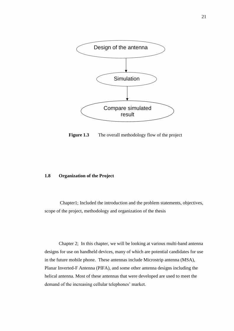
Figure 1.3 The overall methodology flow of the project
1.8 Organization of the Project
Chapter1; Included the introduction and the problem statements, objectives,
scope of the project, methodology and organization of the thesis
Chapter 2; In this chapter, we will be looking at various multi-band antenna
designs for use on handheld devices, many of which are potential candidates for use
in the future mobile phone. These antennas include Microstrip antenna (MSA),
Planar Inverted-F Antenna (PIFA), and some other antenna designs including the
helical antenna. Most of these antennas that were developed are used to meet the
demand of the increasing cellular telephones’ market.
Design of the antenna
Compare simulatedresult
Simulation

22
Chapter 3; Will describe the features and the techniques that can be used in
the planar inverted antenna and its advantages to be implemented in handheld
devices.
Chapter 4 ; In this chapter we discussed the soft ware ZELAND fidelity
and described its advantages over other electromagnetic software ,and we
described the consideration for the design and the structure of the antenna and its
dimension .
Chapter 5; In this chapter we will discuss the accomplished results such as
return loss curve and radiation pattern for each frequency band. In addition, the
directivity of the antenna and analysis of the results.
Chapter 6 ; Contain the facts that we have gained from this project and
what can be done in the future to provide efficient evolution in the mobile
antenna technology . .
69
References
1. Multiband printed PIFA antenna with ground plane capacitive resonator .B.
Sanz-Izquierdo, J. Batchelor and R. Langley.
2. A New Multiband Antenna for WLAN/Cellular Applications. Duixian Liu*
and Brian Gaucher IBM T. J. Watson Research Center, PO Box 218,
Yorktown Heights, NY 10598.
3. planar triple-band antenna for GSM/DCS/GPS operations
Shyh-Tirng Fang; Jyh-Wen Sheen.
4. Miniature Built-In Multiband Antennas for Mobile Handsets Yong-Xin Guo,
Member,
5. Multiband PIFA for WLAN Mobile Terminals P. Nepa, G. Manara, A. A.
Serra, and G. Nenna
6. K. Hirasawa & M. Haneishi, “Analysis, Design, and Measurement of Small
and Low-Profile Antennas”, Artech House, mc, 1992
7. Eugene Borisov, & Thomas Moore, “A Quad-Band Stubby Antenna for
Portable Wireless Devices”, 2001 IEEE Antennas & Propagation Society
International Symposium, Volume 4, pp. 542— 544, 2001

70
8. Triple band planar inverted F antennas for handheld devices C.T.P. Song,
P.S. Hall, H. Ghafouri-Shiraz and D. Wake
9. E-Shaped planar inverted-F antenna with low-absorption for triple-
bandoperation in cellular phones W. Dou, M.Y.W. Chia
10. A Multiband Antenna for Mobile Phonesby Hiroyuki Tamaoka *, Hiroki
Hamada * and Takahiro Ueno
11. PIFA–Planar Inverted F Antenna Iulian Rosu, YO3DAC / VA3IUL
http://www.qsl.net/va3iul