multi-hop time synchronization protocol for ieee 802.11 wireless ad hoc networks
TRANSCRIPT

JOURNAL OF INFORMATION SCIENCE AND ENGINEERING 23, 969-983 (2007)
969
Multi-hop Time Synchronization Protocol for IEEE 802.11 Wireless Ad Hoc Networks*
GUAN-NAN CHEN1, CHIUNG-YING WANG2 AND REN-HUNG HWANG2
1Department of Communication Engineering 2Department of Computer Science and Information Engineering
National Chung Cheng University Chia-Yi, 621 Taiwan
1E-mail: [email protected] 2E-mail: {wjy; rhhwang}@cs.ccu.edu.tw
Clock synchronization is very important for power management protocol in a
multi-hop MANET. However, since MANET is a network temporarily formed by a col-lection of mobile nodes without the aid of any centralized coordinator, clock synchroni-zation is very difficult to achieve. Therefore, most of previous works on power effi-ciency assumed asynchronous clock. As a consequence, a mobile node will waste a lot of power and time waiting for forwarding a packet to its neighbors, due to the lack of in-formation of wakeup times of its neighbors. In this paper, we propose a multi-hop time synchronization protocol, referred to as MTSP, for multi-hop MANETs based on IEEE 802.11 ad hoc mode. The MTSP consists of two phases: beacon window (BW) phase and synchronization (SYN) phase. In BW phase, several devices, which can directly communicate with each others, form a synchronization group. And each group selects the device with fastest timer as the leader node of the group. In SYN phase, leader nodes then synchronize with each other. Our simulation results show that MTSP is a distributed and effective multi-hop time synchronization protocol, especially for dense networks. Keywords: clock synchronization, IEEE 802.11, multi-hop, mobile ad hoc network (MANET), medium access control
1. INTRODUCTION
In recent years, wireless networks have become prevail in our surroundings. The most popular wireless technique is from the set of IEEE 802.11 standards. The IEEE 802.11 supports Infrastructure Mode and Ad Hoc mode. In infrastructure mode, mobile nodes communicate through an access point (AP), which usually connects to the Internet. In the ad hoc mode, mobile nodes dynamically form an ad hoc network and communicate with each others through multi-hop routing. Although infrastructure mode is more commonly adopted, ad hoc mode may be the only solution in some special applications, such as battlefields, disaster areas, and outdoor activities. No matter in which mode, the power of mobile nodes is a limited resource. Without power, any wireless device will become useless. Therefor, power saving becomes a critical issue in wireless networks.
In recent years, several power saving protocols have been proposed for IEEE 802.11 wireless LANs. They can be classified in to two groups: synchronous wake up and Received September 15, 2006; accepted February 6, 2007. Communicated by Ten H. Lai, Chung-Ta King and Jehn-Ruey Jiang. * This paper was partially supported by National Science Council of Taiwan, R.O.C., under grant No. NSC 94-
2213-E-194-001.

GUAN-NAN CHEN, CHIUNG-YING WANG AND REN-HUNG HWANG
970
asynchronous wake up. In the synchronous wake up approach, all nodes wake up at the same time in order to send or receive packets from its neighbors. Thus, time synch- ronization becomes the most important part of this kind of protocols. Examples of synchronous wake up protocols are IEEE 802.11 Power saving protocol [1], and p-MANET [2]. On the other hand, asynchronous wake up protocols do not synchronize wake up time of mobile nodes. Nodes asynchronously wake up a period of time for receiving packets from its neighbors. Examples of asynchronous wake up power saving protocols are [3-5]. Concerns of asynchronous wake up protocols are less power efficiency, longer transmission delay, and difficult to perform broadcast. In this paper, we focus on the design of synchronous wake up power saving protocols.
However, to synchronize mobile nodes in MANET is very difficult, since there is no base station to perform centralized control. Therefore the Pulse protocol [6] synch- ronizated with base station can’t apply in MANET. The IEEE 802.11 Standard has defined a Timing Synchronization Function (IEEE 802.11 TSF) for single-hop ad hoc networks [7]. Mobile nodes generate a beacon with its system time and periodically send a beacon. Nodes can be synchronized by the time information in the beacon. Extension of this protocol for multi-hop ad hoc networks can be found in the literature [8], however synchronization accuracy is still an issue.
In IEEE 802.11, if the synchronization accuracy, i.e., the time difference between the clock of the fastest node and that of the slowest node, is larger than 224μs, which is equivalent to the time to change from one operating channel frequency [1], the network is called “out of synchronization.” Sometimes small clock skew and the defects of IEEE 802.11 TSF may cause the problem of out of synchronization. In [9], Huang and Lai proposed that let faster node have higher priority to send a beacon can improve the synchronization accuracy on single hop ad hoc networks.
In the last few years, several papers have been devoted to the study of time synch- ronization. For example, [10, 11] have proposed time synchronization mechanisms for sensor networks. [12] proposed how to synchronize mobile devices in Bluetooth networks. In [9, 13-15], researchers pointed out that network density may affect the synchronization accuracy in IEEE 802.11 ad hoc networks. [16] showed that time synchronization mechanism for single hop ad hoc networks is not suitable for multi-hop ad hoc networks. Only few attempts so far have been made for time synchronization in multi-hop networks. Sheu et al. [8] proposed a time synchronization scheme, called Automatic Self-time-correcting Procedure (ASP), for multi-hop networks. In ASP, mobile nodes adjust their clocks according to the beacon information among neighbors. In this paper, we proposed a new time synchronization mechanism based on IEEE 802.11 TSF, called Multi-hop Time Synchronization Protocol (MTSP). IEEE 802.11 Standard only defines how to synchronize clocks in single hop networks. Extending TSF to multi-hop networks will cause out of synchronization problem. Our MTSP adapts to both single hop and multi-hop ad hoc networks and improves the synchronization accuracy.
MTSP consists of two phases: Beacon Window (BW) Phase and Synchronization (SYN) Phase. The BW phase tackles the synchronization accuracy problem in high density single-hop networks while the SYN phase solves the time partition problem in multi-hop networks. In BW phase, similar to [16], faster node has higher priority to send beacon. After BW phase, several one-hop synchronization groups will be formed, and the fastest node in each group is selected as the group leader node. At this time, clock skew

MULTI-HOP TIME SYNCHRONIZATION PROTOCOL FOR IEEE 802.11
971
between different groups may be significant, referred to as the time partition problem. The SYN phase solves this problem by synchronizing all of the leader nodes. Our simulation results show that MTSP can achieve very good synchronization accuracy.
This paper is organized as follows: In section 2 we present existing time synchroni- zation mechanisms in IEEE 802.11 ad hoc mode. Section 3 describes the proposed multi- hop time synchronization protocol. Performance analysis of MTSP is given in section 4. Simulation results of MTSP are presented in section 5. Section 6 concludes this paper.
2. TIME SYNCHRONIZATION IN IEEE 802.11 AD HOC MODE
We first summary the IEEE 802.11 TSF as follows: (1) Each node randomly gener-ates a beacon-generation timer in units of microsecond (μs) within the range of (0, 2 * aCWmin * aSlotTime), where aCWmin and aSlotTime are defined in Table 1. When the timer times out, the node will send a beacon with a 64-bit timestamp, (2) If a node re-ceives a beacon before its beacon-generation timer times out, it will cancel the timer and keep quite in this beacon interval, (3) A node will update its clock to synchronize with a faster timestamp it received; and it will ignore slower timestamps and (4) Each node has the same probability to contend sending a beacon.
Table 1. Parameters used in generating beacon timer. FHSS DSSS
aCWmin 15 31 aSlotTime 50μs 20μs
IEEE 802.11 TSF may encounter the “beacon contention problem” in dense net-works where the fastest node cannot send out its beacon due to beacon contention. As a consequence, the network becomes out of synchronization. In [9], “Adaptive Timing Synchronization Procedure” (ATSP) has been proposed to solve beacon contention prob-lem. Lai et al. [13] proposed the “Tiered Adaptive Time Synchronization Procedure” (TATSP) to improve synchronization accuracy of ATSP and reduce the convergence time of synchronization. They also proposed to prioritize the beacon-generation timer such that faster nodes get shorter timers to send beacons in [14]. All of the aforemen-tioned works consider only the single-hop ad hoc environment. In [16], the authors showed that directly extending the single-hop time synchronization protocol to multi-hop environment will encounter the time partition problem.
The time synchronization problem in multi-hop ad hoc networks is first studied in [8]. An automatic self-time-correcting procedure (ASP) was proposed. However, the convergence time of synchronization is too long and out of synchronization still may occur.
3. MULTI-HOP TIME SYNCHRONIZATION PROTOCOL
In this section, we present our multi-hop time synchronization protocol (MTSP) for the IEEE 802.11 multi-hop ad hoc network. The main design goals are: (1) Improve syn-

GUAN-NAN CHEN, CHIUNG-YING WANG AND REN-HUNG HWANG
972
chronization accuracy, especially in high density networks, (2) Avoid the out of synchro-nization problem and (3) Solve the time partition problem.
Unlike the IEEE 802.11 TSF, the basic idea of MTSP is to have fast nodes to be-come leader nodes and have higher priority to send beacon, like [14]. A leader node can synchronize its one-hop neighbor nodes easily and form a synchronization group. After synchronization groups are formed, MTSP then tries to synchronize those groups by syn-chronizing leader nodes. Therefore, MTSP consists of two phases: beacon window phase and synchronization phase. Details are described as follows. 3.1 System Architecture
MTSP operates under the network layer and above the physical layer; it provides the synchronization information for power management protocols.
In MTSP, time is synchronized and divided into beacon intervals. Each beacon in-terval is composed of four windows: (1) Beacon Window: nodes generate a random timer to contend to send beacons in the beacon window, (2) Synchronization Window (SYNC window): leader nodes synchronize with each others in the synchronization window; other nodes stay at idle state, (3) ATIM Window: ATIM window is the same as the IEEE 802.11 Standard. A node uses the ATIM frame to announce data frames that are to be transmitted in the data window and (4) Data Window: Data window is used for transmit-ting and receiving data frames. Nodes that send or receive ATIM frames will stay at ac-tive mode in data window.
Fig. 1. Beacon interval of MTSP.
Fig. 1 shows the beacon interval of MTSP. The length of a beacon interval is 100
ms, as suggested by the IEEE 802.11 standard. MTSP adds a 4-ms beacon window and a 6-ms sync window. The length of beacon window is the same as that of IEEE 802.11 standard. The length of sync window is 1.5 times more than that of beacon window. The length of ATIM window is 20 ms, same as that of IEEE 802.11 standard.
3.2 Beacon Window Phase
Beacon window phase is designed based on IEEE 802.11 TSF. Nodes use random timers to contend for wireless medium to send beacons with 64-bit timestamp. By fol-lowing the fastest node, nodes can be synchronized. The length of beacon packet is 50 bytes, same as defined in the IEEE 802.11 standard.
The beacon-generation timer, BWTimer, is managed as follows such that faster

MULTI-HOP TIME SYNCHRONIZATION PROTOCOL FOR IEEE 802.11
973
nodes have higher priority to transmit beacons. First of all, nodes are either in high prior-ity (HI) state or low priority (LO) state. Nodes in HI state will randomly generate BWTimer within the range of (0, 1/2 beacon window length) while nodes in LO state generate BWTimer within the range of (1/2 beacon window length, beacon window length). The design goal is to have the fastest node of a synchronization group to stay in HI state while the rest of nodes to stay in LO state such that the fastest node can send out its beacon without contention. However, if a node in LO state becomes faster, it still has the chance to announce its beacon.
The flow chart of the beacon window (BW) phase operation is shown in Fig. 2. Nodes are grouped into synchronization groups in a self-organizing way. A synchroniza-tion group is centered at a node with the fastest system time among all nodes in the same group. The BW phase operates as follows:
Fig. 2. Flow chart of beacon window phase.
(1) All nodes are in HI State initially. (2) At the beginning of a beacon interval, each node generates its BWTimer randomly,
according to its state. (3) Each node then counts down its BWTimer timer. A node will send out a beacon with
its system time when BWTimer expires and enter the HI state. The node should still remain in active mode and receive beacons until the end of the beacon window. If it receives a beacon with a faster timestamp, it proceeds to step (4).
(4) If a node receives a beacon with a timestamp that is faster than its clock before or after its BWTimer expires, it will synchronize its clock to the timestamp, cancel its BWTimer if necessary, and enter the LO state. The node should keep receiving bea-cons and repeating this step until the end of beacon window and update its clock if a faster timestamp is received.
According to above operations, let us discuss a special case that if a node receives a
beacon with a faster timestamp after BWTimer time out, it will change system time and

GUAN-NAN CHEN, CHIUNG-YING WANG AND REN-HUNG HWANG
974
enter the LO state until Beacon Window time out. In this case, even this node can not receive any more beacons with even faster timestamp; it will follow the BW phase op-erations while entering next Beacon Window.
3.3 Synchronization Phase
The purpose of synchronization phase is to solve the time partition problem [16]. In
multi-hop ad hoc networks, nodes can only receive beacon from its neighbors. Therefore, the beacon of the fastest node cannot be received by nodes that are not within the fastest node’s transmission range. A mechanism thus is required to broadcast the beacon of the fastest node to all nodes in the ad hoc network.
The basic idea of the synchronization (SYN) phase is to synchronize leader nodes which in turn synchronize nodes in their group. Let us consider the example shown in Fig. 3 where there are four leader nodes A, B, R, and S. The clock rates in decreasing order are A > R > S > B. Power level will be increased for communication between leader nodes, which will be described in more detail later. As shown in Fig. 3, let us as-sume that node A can communicate directly with node R, node R can communicate di-rectly with node S, and node S can communicate directly with node B. Now, if node A sends a synchronization packet with its timestamp to node R, and node R relays to node S, and then to node B, these four leader nodes can then be synchronized.
Fig. 3. Basic idea of synchronization phase.
Before describing the algorithm of the synchronization phase, let us define the syn-chronization packet format first. The synchronization (SYN) packets are classified into three types: (1) SYNC-Query: SYNC-Query packet is used by a leader node to query if there are other faster leader nodes within SYN packet transmission range. Each leader node sends a SYNC-Query, which carries its 64-bit timestamp, in the synchronization phase, (2) SYNC-ACK: a SYNC-ACK packet is used to respond a SYN-Query packet with slower timestamp and (3) SYNC-RACK: when a leader node receives a SYNC- Query with a faster timestamp, it will update its system time and send a SYNC-RACK to notify its neighbor leader nodes.
Fig. 4 shows the format of the synchronization packet. The 50-byte frame shares the same format as the beacon packet. It can be considered as a frame control packet of IEEE 802.11 MAC layer. Different types of synchronization are differentiated by the frame control field, as shown in Fig. 4.
Recall that more than one synchronization groups may be formed after the BW phase. Nodes that are in HI-state will become the leader nodes of synchronization groups. Only leader nodes will involve in the SYN phase. Similar to BWTimer, each leader node maintains a randomly generated MTSF timer and will send a SYNC-Query packet when

MULTI-HOP TIME SYNCHRONIZATION PROTOCOL FOR IEEE 802.11
975
Fig. 4. Format of synchronization packet.
Fig. 5. Flow chart of the synchronization phase.
this timer expires. The flow chart of SYN phase is shown in Fig. 5. The algorithm is de-scribed as follows: (1) Each leader node randomly generates a MTSF timer within the range of [0,
MTSFmax], where MTSFmax is set to 2 * aCWmin * aSlotTime initially. MTSF timer is re-generated at the beginning of each SYN phase.
GUAN-NAN CHEN, CHIUNG-YING WANG AND REN-HUNG HWANG
976
(2) A leader node sends a SYNC-Query packet when its MTSF timer expires. It should maintain in active state to receive other SYN packets until the end of SYNC win-dow.
(3) Upon receiving a SYNC-Query packet with a faster timestamp from neighbor leader nodes, it will synchronize its clock to the timestamp and send a SYNC-RACK packet to notify other neighbor leader nodes. On the other hand, if the timestamp is slower, it sends a SYNC-ACK to notify sender which includes its timestamp.
(4) Upon receiving a SYNC-ACK or a SYNC-RACK packet, it should update its clock if the received timestamp is faster.
(5) A leader node stays active until the end of SYNC window. (6) If a leader node never updates its clock during the SYNC window which means it is
the fastest node among its neighbors, then it decreases its MTSFmax to max(1, MTSFmax − 1). Otherwise, it increases MTSFmax to min(MTSFmax + 1, SYNC window length).
(7) If a leader node never updates its clock during the SYNC window which means it is the fastest node among its neighbors, then it decreases its MTSFmax to max(1, MTSFmax − 1). Otherwise, it increases MTSFmax to min(MTSFmax + 1, SYNC window length). Let us illustrates the SYN phase using a simple example. Assume that there are four
leader nodes A, B, C, and D. The clock rate of these four nodes in decreasing order is A > B > C > D. Further assume that node A can directly communicate with node B; node B can communicate with node A and C; node D can communicate with node C.
Fig. 6 shows the SYN phase of the first beacon interval. Without loss of generality, let us assume that the order of randomly generated MTSF timer is A > B > C > D. Firstly, node D sends a SYNC-Query packet to node C. Upon receiving this packet, node C re-plies a SYNC-ACK to node D since node C is faster than node D. Node D will synchro-nize its clock to that of node C, denoted by Tc. Later on, node C sends out a SYNC-Query when its MTSF timer expires. Similarly, node B replies a SYNC-ACK to node C since it is faster. As a consequence, node C updates its clock to Tb, the system timestamp of node B. Later on, node B sends out a SYNC-Query. Node C updates its clock again upon receiving this packet. Node C also sends a SYNC-RACK to notify its neighbor leader nodes such that node D also synchronizes its clock to that of node B. Finally, node A sends out its SYNC-Query when its MTSF timer expires. This time, node B synchronizes its clock with node A and sends a SYNC-RACK to notify node C. When the SYNC window ends, node A, B, and C have synchronized their clocks, while node D needs another round of SYN phase in order to synchronize its clock with the fastest node, node A. After the first beacon interval, node B, C, and D have received faster timestamp from other nodes, so they will increase their MTSFmax by one slot time at next beacon interval in order to decrease the priority of sending SYNC-Query packets. On the other hand, node A decreases its MTSFmax by one.
Fig. 7 shows the SYN phase of the second beacon interval. Here, we assume the or-der of the randomly generated MTSF timers is C > D > A > B. So, node C sends a SYNC-Query first. Upon receiving this packet, node D updates its clock while node B replies a SYNC-ACK which updates node C’s clock. Later on, node D sends a SYNC- Query and node C replies with a SYNC-ACK which synchronizes node D’s clock to Tb.

MULTI-HOP TIME SYNCHRONIZATION PROTOCOL FOR IEEE 802.11
977
Fig. 6. SYN phase of the first beacon interval. Fig. 7. SYN phase of the second beacon interval.
The fastest leader node A sends SYNC-Query next. Upon receiving this packet, node B updates its clock and sends out a SYNC-RACK to notify node C. Node B and node C now synchronize with node A. Finally, node B sends a SYNC-Query which causes node C to send a SYNC-RACK to node D. After node D receives this SYNC-RACK, all nodes synchronize with node A.
4. DESIGN ISSUES AND PERFORMANCE OF MTSP
4.1 Transmission Range
The purpose of beacon is to synchronize nodes in a synchronization group, which can be considered as local synchronization. On the other hand, synchronization packet is used to synchronize leader nodes, which is to achieve global synchronization. For power saving and transmission efficiency, we propose to have different power levels when transmitting these two kinds of packets. That is, use a lower power to transmit beacon and a higher power for synchronization. As a consequence, the transmission range of beacon is smaller than that of synchronization packet.
Let the transmission range of beacon be R. We show that in an ideal environment (not considering interfering, fading, …), the distance between two leader nodes, D, is bounded by (R, 3R). We shall only consider the case that the network is not partitioned. The proof is given as follows:
Theorem The distance between two leader nodes, D, is bounded by R < D <= 3R.
Proof: R < D: This is trivial since if the distance is less than D, they would hear each other’s beacon packets, and the slower should be synchronized to the faster, not becom-ing the leader node. D <= 3R: Fig. 8 shows the worst case where node A and D are leader nodes, and node B and C are normal nodes. AB and CD cannot be larger than R. So, if AD > 3R, then BC must greater than R. However, in that case, the network becomes partitioned which violates our assumption that network is not partitioned. Therefore, the distance between two leader nodes must be less than 3R.
As a sequence, the transmission power of synchronization packets should be set such that its transmission range is less than 3R. In our simulation, we will show the re-sults of setting the transmission range to 2R as well as 3R.

GUAN-NAN CHEN, CHIUNG-YING WANG AND REN-HUNG HWANG
978
Fig. 8. Transmission range between leader nodes. Fig. 9. Example of forming different SYN groups.
4.2 BW Phase Synchronization
In this section, we discuss the stability problem of the BW phase. In particular, we discuss how different synchronization groups can be formed distributedly. The major concern is that all nodes should either be a leader node or a group member of a leader node. Consider the topology shown in Fig. 9, where the order of the clock rate is A < B < C. Without loss of generality, assume that in the first beacon interval, node B sends a beacon first. Node A will set node B as its leader node and turn into LO State. Node C ignores beacon from node B. Node C sends a beacon when its BWTimer times out. After node B received the beacon from node C, node B considers node C as its leader node and turn into LO State. In the second beacon interval, node C stays in HI State and sends a beacon first. Node B cancels its BWTimer and keeps quiet. Therefore, node A will not receive any beacon before its BWTimer times out. Node A then sends out its beacon and returns to HI State. As a consequence, two synchronization groups, with leader nodes A and C, will be formed in the third beacon interval.
Next, we discuss the maximum clock skew within a synchronization group. Let the maximum difference of the clock rates of the leader node and a member node is d per time slot. Let the length of the beacon interval be BI slots and that of beacon window be BWL slots. The leader node will send out a beacon every beacon interval at the first 1/2 beacon window. Therefore, the maximum clock skew is given by d * (BI + 0.5 * BWL).
4.3 SYN Phase Synchronization
Now we discuss the maximum clock skew among leader nodes. Assume the net-work diameter is K, i.e., the maximum distance between any two leader nodes is K − 1 hops. In the worst case, it takes K − 1 rounds (beacon intervals) to have the timestamp of the fastest node be transmitted to the lowest node. Therefore, the maximum clock skew between any two leader nodes is given by d * (BI * (K − 1) + BWL + SYNL), where SYNL is the length of SYN phase.
5. SIMULATIONS
Effectiveness of the multi-hop time synchronization protocol (MTSP) is evaluated by simulations in this section. We implemented the MTSP simulator in C language.
5.1 Simulation Metrics
Most of the system parameters in our simulations are set according to IEEE 802.11 standard. Direct Sequence Spread Spectrum (DSSS) modulation scheme is adopted. The

MULTI-HOP TIME SYNCHRONIZATION PROTOCOL FOR IEEE 802.11
979
beacon interval is set to 0.1 second. The clock accuracy of nodes is uniformly distributed in the range of [− 0.01%, + 0.01%]. Constants in Table 1 are used for slot time and gen-eration of beacon window timers. The maximum tolerable clock skew is 224μs.
Other system parameters are set as follows: 50 to 300 nodes are simulated, which are randomly placed in a 1,000m × 1,000m area. The transmission range of beacons is 125m and that of synchronization packets is 250m. All nodes move according to the ran-dom way-point model [17], with a maximum speed of 20m/s and pause time of 20 sec-onds.
Independent simulations are run to gather statistic results. Each point in figures is the average of ten simulation runs with simulation time of 300 seconds (5,000 beacon intervals). Maximum clock skew is measured as the difference of clocks of the fastest node and the slowest node. Following performance metrics are observed: (1) Out of synchronization percentage: Out of synchronization percentage is the ratio of out of syn-chronization time to the total simulation time, (2) Synchronization accuracy: The maxi-mum clock skew at an instant of time or over a time period (beacon interval or whole simulation), and (3) Synchronization overhead: The amount of synchronization packets sent is used as the performance metric for synchronization overhead. It is defined as the sum of beacon and synchronization packets in the whole simulation.
5.2 Simulation Results
First, we evaluate the proper transmission range of synchronization packets. We simulate 50 nodes in an area of 1,000m × 1,000m with a maximum mobility speed of 5 m/s. The beacon transmission range is 125m; synchronization packet transmission ranges are 225m, 250m, 312m, and 375m, which are equivalent to a ratio of 1.8, 2, 2.5, and 3 to the beacon transmission range.
As shown in Table 2, as the transmission range of synchronization packet increases, synchronization accuracy also improved. The rationale is intuitive, the larger the range, the faster spreading the timer information. However, the total number of SYN packets transmitted is also increases because more SYNC-ACK and SYNC-RACK packets are sent per leader node. We also observed that, in all simulations, there is no network parti-tion problem when the ratio of the transmission range of the synchronization packets to that of beacon packets is 3. This confirms to our analysis in section 4.1. In fact, there is no network partition problem in all simulations when the ratio is greater than 2. For bet-ter power saving, it is thus suggested that the ratio of transmission range could be set to 2. This ratio is also adopted in following simulations.
Table 2. Evaluation of transmission range of SYN packets. Syn/Beacon ratio 1.8 2 2.5 3
Synchronization Accuracy 29.5μs 26.2μs 24.6μs 23.6μs Total number of SYN packets 253967 291257 400026 586357
5.2.1 Out of synchronization percentage
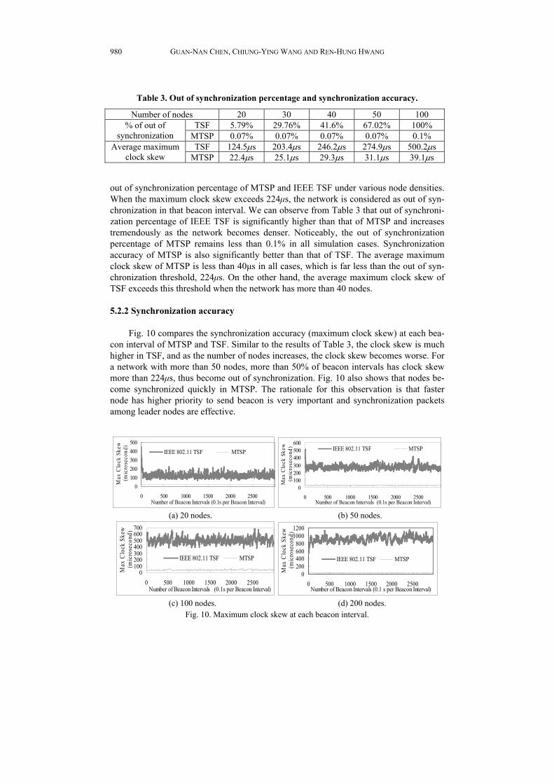
Intuitively, out of synchronization percentage is affected by node density. Therefore, we evaluate the impact of node density on the performance of MTSP. Table 3 shows the
GUAN-NAN CHEN, CHIUNG-YING WANG AND REN-HUNG HWANG
980
Fig. 10. Maximum clock skew at each beacon interval.
Table 3. Out of synchronization percentage and synchronization accuracy.
Number of nodes 20 30 40 50 100 TSF 5.79% 29.76% 41.6% 67.02% 100% % of out of
synchronization MTSP 0.07% 0.07% 0.07% 0.07% 0.1% TSF 124.5μs 203.4μs 246.2μs 274.9μs 500.2μs Average maximum
clock skew MTSP 22.4μs 25.1μs 29.3μs 31.1μs 39.1μs
out of synchronization percentage of MTSP and IEEE TSF under various node densities. When the maximum clock skew exceeds 224μs, the network is considered as out of syn-chronization in that beacon interval. We can observe from Table 3 that out of synchroni-zation percentage of IEEE TSF is significantly higher than that of MTSP and increases tremendously as the network becomes denser. Noticeably, the out of synchronization percentage of MTSP remains less than 0.1% in all simulation cases. Synchronization accuracy of MTSP is also significantly better than that of TSF. The average maximum clock skew of MTSP is less than 40μs in all cases, which is far less than the out of syn-chronization threshold, 224μs. On the other hand, the average maximum clock skew of TSF exceeds this threshold when the network has more than 40 nodes. 5.2.2 Synchronization accuracy
Fig. 10 compares the synchronization accuracy (maximum clock skew) at each bea-
con interval of MTSP and TSF. Similar to the results of Table 3, the clock skew is much higher in TSF, and as the number of nodes increases, the clock skew becomes worse. For a network with more than 50 nodes, more than 50% of beacon intervals has clock skew more than 224μs, thus become out of synchronization. Fig. 10 also shows that nodes be-come synchronized quickly in MTSP. The rationale for this observation is that faster node has higher priority to send beacon is very important and synchronization packets among leader nodes are effective.
0100200300400500
0 500 1000 1500 2000 2500Number of Beacon Intervals (0.1s per Beacon Interval)
Max
Clo
ck S
kew
(mic
rose
cond
)
IEEE 802.11 TSF MTSP
0100200300400500600
0 500 1000 1500 2000 2500Number of Beacon Intervals (0.1s per Beacon Interval)
Max
Clo
ck S
kew
(mic
rose
cond
) IEEE 802.11 TSF MTSP
(a) 20 nodes. (b) 50 nodes.
0100200300400500600700
0 500 1000 1500 2000 2500Number of Beacon Intervals (0.1s per Beacon Interval)
Max
Clo
ck S
kew
(mic
rose
cond
)
IEEE 802.11 TSF MTSP
0200400600800
10001200
0 500 1000 1500 2000 2500Number of Beacon Intervals (0.1 s per Beacon Interval)
Max
Clo
ck S
kew
(mic
rose
cond
)
IEEE 802.11 TSF MTSP
(c) 100 nodes. (d) 200 nodes.

MULTI-HOP TIME SYNCHRONIZATION PROTOCOL FOR IEEE 802.11
981
Table 4 examines the impact of mobility on MTSP and TSF. A 50-node network is simulated and the average maximum synchronization skews under various mobility speeds are observed. Interestingly, clock skew in TSF increases as speed increases, while it decreases in MTSP. The rationale is that, in TSF, faster node may move into high dense area such that it has less chance to send beacons. However, in MTSP, faster node has higher priority to send beacon such that mobility helps spreading timestamp of the fastest node.
Table 4. Max. Clock skew under different mobility speed.
5m/s 10m/s 15m/s 20m/s TSF 272.9μs 274.5μs 281μs 323.8μs
MTSP 36.9μs 27.3μs 27.6μs 21.7μs
5.2.3 Synchronization overhead
Synchronization overhead is measured by the beacon and synchronization packets
transmitted by the synchronization protocol. Fig. 11 compares the averaged total number of beacons and synchronization packets transmitted by TSF and MTSP in a 300-second simulation run. We can see that MTSP has higher overhead than TSF when the network is sparse. As the network becomes denser, TSF and MTSP have competitive overhead. MTSP requires more synchronization overhead because the synchronization packets sent in the SYN phase. This additional overhead is paid off by higher synchronization accuracy.
0
500000
20 50 100 200 Number of Nodes
sync
hro-
niza
tion
Pac
kets IEEE 802.11 TSF
MTSP
Fig. 11. Synchronization overhead under various network densities.
6. CONCLUSION
In this paper, we presented a time synchronization protocol, MTSP, for synchroni-zation multi-hop ad hoc networks. Based on two synchronization phases, MTSP has been shown to have high synchronization accuracy. MTSP is especially suitable for high den-sity networks as it not only provide high synchronization accuracy but also yield com-petitive overhead as compare to IEEE TSF.
Power saving and time synchronization are both important issues for wireless and sensor networks. Therefore, we are currently designing a power saving protocol based on MTSP. We are also investigating the time synchronization issue in sensor networks. More design issues and parameter analysis are required; and further, the comparison of MTSP and other related works are also being studied.

GUAN-NAN CHEN, CHIUNG-YING WANG AND REN-HUNG HWANG
982
REFERENCES
1. IEEE Std 802.11 − IEEE Computer Society LAN MAN Standards Committee, Wireless LAN Medium Access Control (MAC) and Physical Layer (PHY) Specifi-cations, 1999.
2. C. Y. Wang, C. J. Wu, G. N. Chen, and R. H. Hwang, “p-MANET: efficient power saving protocol for multi-hop mobile ad hoc networks,” in Proceedings of the 3rd IEEE International Conference on Information Technology and Applications, 2005, pp. 271-276.
3. Y. C. Tseng, C. S. Hsu, and T. Y. Hsieh, “Power saving protocols for IEEE 802.11- based multi-hop ad hoc network,” Computer Networks: The International Journal of Computer and Telecommunications Networking, 2003, pp. 317- 337.
4. J. R. Jiang, Y. C. Tseng, C. S. Hsu, and T. H. Lai, “Quorum-based asynchronous power-saving protocols for IEEE 802.11 ad hoc networks,” in Proceedings of IEEE International Conference on Parallel Processing, 2003, pp. 257-264.
5. R. Zheng, J. C. Hou, and L. Sha, “Asynchronous wakeup for ad hoc networks,” in Proceedings of the ACM International Symposium on Mobile Ad Hoc Networking & Computing, 2003, pp. 35-45.
6. B. Awerbuch, D. Holmer, and H. Rubens, “The pulse protocol: energy efficient in-frastructure access,” in Proceedings of the 23rd Conference of the IEEE Communi-cations Society INFOCOM, 2004, pp. 1467-1478.
7. Task Group E of the IEEE 802.11 standards group, http://grouper.ieee.org/groups/ 802.11.
8. J. P. Sheu, C. M. Chao, and C. W. Sun, “A clock synchronization algorithm for multi-hop wireless ad hoc networks,” in Proceedings of IEEE International Confer-ence on Distributed Computing Systems, 2004, pp. 574-581.
9. L. Huang and T. H. Lai, “On the scalability of IEEE 802.11 ad hoc networks,” in Proceedings of ACM International Symposium on Mobile Ad Hoc Networking & Computing, 2002, pp. 173-182.
10. M. L. Sichitiu and C. Veerarittiphan, “Simple, accurate time synchronization for wireless sensor networks,” in Proceedings of IEEE Wireless Communications and Networking, 2003, pp. 1266-1273.
11. R. Kumar, M. B. Srivastava, and S. Ganeriwal, “Timing-sync protocol for sensor networks,” in Proceedings of ACM Conference on Embedded Networked Sensor Systems, 2003, pp. 138-149.
12. K. V. S. S. S. S. Sairam, N. Gunasekaran, and S. R. Reddy, “Bluetooth in wireless communication,” IEEE Communications Magazine, 2002, pp. 90-96.
13. T. H. Lai and D. Zhou, “Efficient and scalable IEEE 802.11 ad hoc mode timing synchronization function,” in Proceedings of IEEE International Conference on Ad-vanced Information Networking and Applications, 2003, pp. 318-323.
14. D. Zhou and T. H. Lai, “Analysis and implementation of scalable clock synchroniza-tion protocols in IEEE 802.11 ad hoc networks,” in Proceedings of Mobile Ad Hoc and Sensor Systems, 2004, pp. 255-263.
15. M. H. Ye, C. T. Lau, and A. B. Premkumar, “A modified time synchronization func-tion in IEEE 802.11 using differentiated contention window,” in Proceedings of IEEE International Conference on Information and Communication Security, 2003,

MULTI-HOP TIME SYNCHRONIZATION PROTOCOL FOR IEEE 802.11
983
pp. 1076-1080. 16. P. Rauschert, A. Honarbacht, and A. Kummert, “On the IEEE 802.11 IBSS and its
timer synchronization function in multi-hop ad hoc networks,” in Proceedings of IEEE International Symposium on Wireless Communication Systems, 2004, pp. 304- 308.
17. J. Broch, D. Maltz, D. Johnson, Y. Hu, and J. Jetcheva, “A performance comparison of multi-hop wireless ad hoc network routing protocols,” in Proceedings of the 4th Annual ACM/IEEE International Conference on Mobile Computing and Networking, 1998, pp. 85-97.
Guan-Nan Chen (陳冠男) received his B.S. degree in In-formation and Computer Engineering from the Chung Yuan Christian University, Taiwan, in 2003 and the M.S. degrees in Communications Engineering from the National Chung Cheng University, Taiwan, in 2005. His research interests include mobile ad hoc networks, IPv6 networks, and P2P networks.
Chiung-Ying Wang (王瓊英) received her B.S. and M.S. in Computer Science Engineering from University of Yuan Ze, Chungli, Taiwan, in 1997 and in 2001, respectively. In April 2001, she joined Department Information Management of the Technology of Transworld Institute as a lecture. Currently, she is pursuing her Ph.D. degree at National Chung Cheng University. Her research interests include peer-to-peer applications, ad hoc networks, and pervasive computing.
Ren-Hung Hwang (黃仁竑) received his B.S. degree in Computer Science and Information Engineering from National Taiwan University, Taipei, Taiwan, in 1985, and the M.S. and Ph.D. degrees in Computer Science from University of Massa-chusetts, Amherst, Massachusetts, USA, in 1989 and 1993, re-spectively. He joined the Department of Computer Science and Information Engineering, National Chung Cheng University, Chia-Yi, Taiwan, in 1993, where he is now a professor and the chair of the Department of Information Science and Computer Engineering. His research interests include Web 2.0, peer-to-peer applications, ad hoc networks, e-learning, and 3G.