multimedia performance: beginnings · “my tapes are made on the scanimate ‘computer’ system...
TRANSCRIPT
7
Multimedia Performance:
Beginnings

8
This page intentionally left blank.
9

10
This page intentionally left blank.
11
In early October, 1972, I put together a program for my first, one-person show at
the Kitchen in New York City. I wrote –
“My tapes are made on the Scanimate ‘computer’ system built by Computer Image Corporation. Scanimate is a first generation video synthesizer. Images are input in a number of ways – through two 1000-line b&w vidicon cameras (these cameras may look at static artwork, a TV monitor, etc), from an Ampex 2” quad VTR, or from a studio camera. Two of these input channels pass through a video mixer to the Scanimate CPU (Central Processing Unit) where position and size of the image are controlled. The input TV raster may be repositioned right or left, up or down; it may be reduced in width or length (height); it may be reduced in overall size to a point or through a point reappearing inverted and mirror image. “Also on the CPU are three oscillators. The horizontal oscillator repositions the raster lines left to right producing a wave-like distortion running up or down thru the image. The vertical oscillator repositions the raster lines up and down producing a rolling distortion. The depth oscillator effects the overall size of the raster producing at low frequencies a pulsating zoom and at higher frequencies a 3D roll distortion. The CPU also controls the axis (the lines about which an image folds) and allows the image to broken into as many as five separate sections. “The Animation Aid provides five more oscillators, timing control, and a patch panel allowing separate control over individual sections. There are two high speed oscillators (15KHz up), which may be phase locked to the horizontal sync pulse (low speed oscillators lock to the vertical sync pulse). There is a special pair of oscillators running 90 degrees out of phase, which are used to generate circles, spirals and diamond shapes and, finally, one additional low speed oscillator similar to those on the CPU. The oscillators on the Animation Aid allow amplitude modulation. Through the patch panel these oscillators may drive horizontal, vertical, depth, width, length, axis, or intensity. “The animated image is output from the CPU to a high resolution CRT display. It is rescanned with a plumbicon camera at standard TV rates (525 lines/frame 15,750 lines/sec). The output of the rescan camera goes to the Colorizer. “At the input to the Colorizer the image is encoded into five grey levels. Any color may be keyed over the grey level by using the Red, Green, Blue slider pots assigned to that level. The electronically colored image then goes to a switcher where other video signals may be mixed, keyed, or become background replacing one of the grey levels. “I play Scanimate as an instrument and all my tapes are made in real time without preprogramming. I also try to avoid editing. I am designing and hope to build a live performance video synthesizer using components of the Scanimate system and adding portable cameras, an eight level colorizer, a controlled feedback loop and ½” and 1” color tape input and output. Most of my tapes have a score as in music. I am slowly developing a notation system representing the basic animations available on a video synthesizer. I include with these notes a brief outline of these notation symbols and two scores.”
12
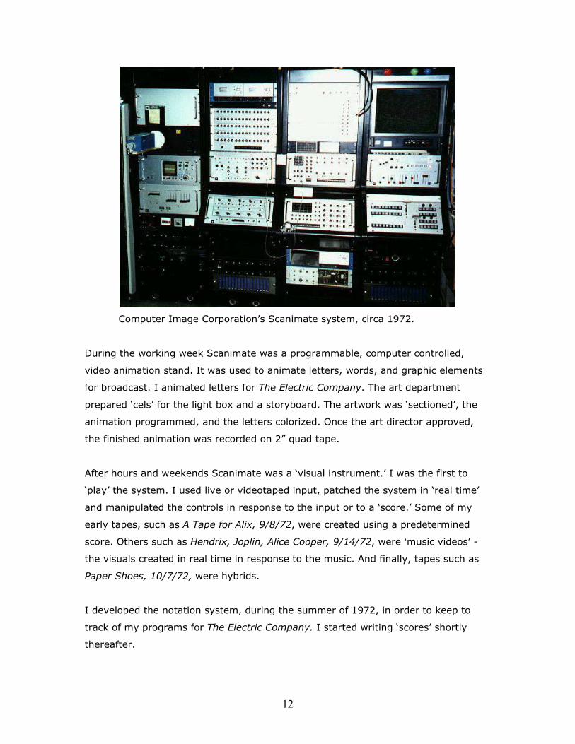
Computer Image Corporation’s Scanimate system, circa 1972.
During the working week Scanimate was a programmable, computer controlled,
video animation stand. It was used to animate letters, words, and graphic elements
for broadcast. I animated letters for The Electric Company. The art department
prepared ‘cels’ for the light box and a storyboard. The artwork was ‘sectioned’, the
animation programmed, and the letters colorized. Once the art director approved,
the finished animation was recorded on 2” quad tape.
After hours and weekends Scanimate was a ‘visual instrument.’ I was the first to
‘play’ the system. I used live or videotaped input, patched the system in ‘real time’
and manipulated the controls in response to the input or to a ‘score.’ Some of my
early tapes, such as A Tape for Alix, 9/8/72, were created using a predetermined
score. Others such as Hendrix, Joplin, Alice Cooper, 9/14/72, were ‘music videos’ -
the visuals created in real time in response to the music. And finally, tapes such as
Paper Shoes, 10/7/72, were hybrids.
I developed the notation system, during the summer of 1972, in order to keep to
track of my programs for The Electric Company. I started writing ‘scores’ shortly
thereafter.
13
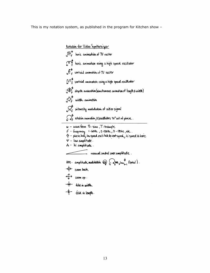
This is my notation system, as published in the program for Kitchen show –
14
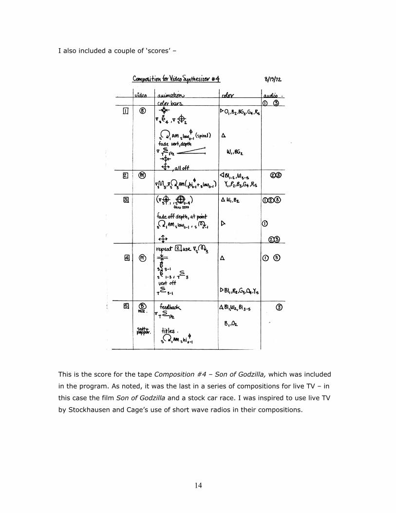
I also included a couple of ‘scores’ –
This is the score for the tape Composition #4 – Son of Godzilla, which was included
in the program. As noted, it was the last in a series of compositions for live TV – in
this case the film Son of Godzilla and a stock car race. I was inspired to use live TV
by Stockhausen and Cage’s use of short wave radios in their compositions.

15
A second score was included in the program -
A Tape for Alix, uses prerecorded video clips that are animated and edited back
together according to the score. As I remember it, this tape was slower and more
structured than the ‘music videos.’ It was my first attempt to ‘tease’ animation from
the visual content of a series of video clips.
16
This idea of finding an animation for a specific image came from working with the
letters for the Electric Company. The letters often appear one at a time, as the word
was spelled, and move to form the word. Where do they start? How should they
move? An ‘o’ would probably roll into place. An ‘s’ would hop into the frame, flexing
like spring. An ‘m’ would inchworm into place. The last letter might enter at the ‘last’
minute from the right edge of the frame, bump up against the other letters in the
word bringing the animation, and the word, to end with the visual equivalent of a
‘period’ - visual punctuation. Sometimes the word itself influences the animation –
the word ‘float’ for example.
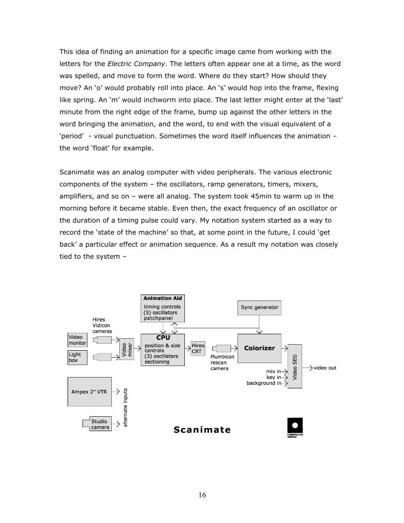
Scanimate was an analog computer with video peripherals. The various electronic
components of the system – the oscillators, ramp generators, timers, mixers,
amplifiers, and so on – were all analog. The system took 45min to warm up in the
morning before it became stable. Even then, the exact frequency of an oscillator or
the duration of a timing pulse could vary. My notation system started as a way to
record the ‘state of the machine’ so that, at some point in the future, I could ‘get
back’ a particular effect or animation sequence. As a result my notation was closely
tied to the system –
17
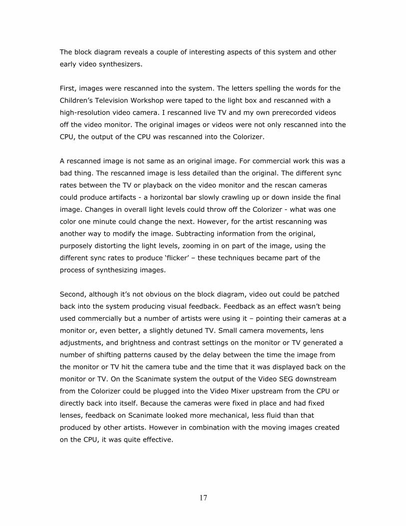
The block diagram reveals a couple of interesting aspects of this system and other
early video synthesizers.
First, images were rescanned into the system. The letters spelling the words for the
Children’s Television Workshop were taped to the light box and rescanned with a
high-resolution video camera. I rescanned live TV and my own prerecorded videos
off the video monitor. The original images or videos were not only rescanned into the
CPU, the output of the CPU was rescanned into the Colorizer.
A rescanned image is not same as an original image. For commercial work this was a
bad thing. The rescanned image is less detailed than the original. The different sync
rates between the TV or playback on the video monitor and the rescan cameras
could produce artifacts - a horizontal bar slowly crawling up or down inside the final
image. Changes in overall light levels could throw off the Colorizer - what was one
color one minute could change the next. However, for the artist rescanning was
another way to modify the image. Subtracting information from the original,
purposely distorting the light levels, zooming in on part of the image, using the
different sync rates to produce ‘flicker’ – these techniques became part of the
process of synthesizing images.
Second, although it’s not obvious on the block diagram, video out could be patched
back into the system producing visual feedback. Feedback as an effect wasn’t being
used commercially but a number of artists were using it – pointing their cameras at a
monitor or, even better, a slightly detuned TV. Small camera movements, lens
adjustments, and brightness and contrast settings on the monitor or TV generated a
number of shifting patterns caused by the delay between the time the image from
the monitor or TV hit the camera tube and the time that it was displayed back on the
monitor or TV. On the Scanimate system the output of the Video SEG downstream
from the Colorizer could be plugged into the Video Mixer upstream from the CPU or
directly back into itself. Because the cameras were fixed in place and had fixed
lenses, feedback on Scanimate looked more mechanical, less fluid than that
produced by other artists. However in combination with the moving images created
on the CPU, it was quite effective.
18
In late November, 1972, I showed my tapes at the Annual Avant-Garde Art
Festival. Near the entrance Ralph Hocking sat inside his simultaneously erotic and
flatulent sound installation. During the course of the day Ralph saw my videos.
Shortly thereafter Ralph invited me to join the Experimental Television Center as
artist-in-residence.
“The experimental fusion of new technologies, collaborative work, performance, and real-time mediated imaging form the core of the history of performance multimedia. The Experimental Television Center in Owego, New York, founded in 1971 by Ralph Hocking … has functioned as one of the epicenters for the germination of live video performance. ‘Performance-based works were some of the earliest media art created at the Center with the image-processing tools we made available through the residency program’ explains Sherry Miller Hocking, assistant director of the ETC.” From Live! Reconnecting the Histories of Live Multimedia Performance; Patricia Zimmerman in A Closer Look, NAMAC 2005.
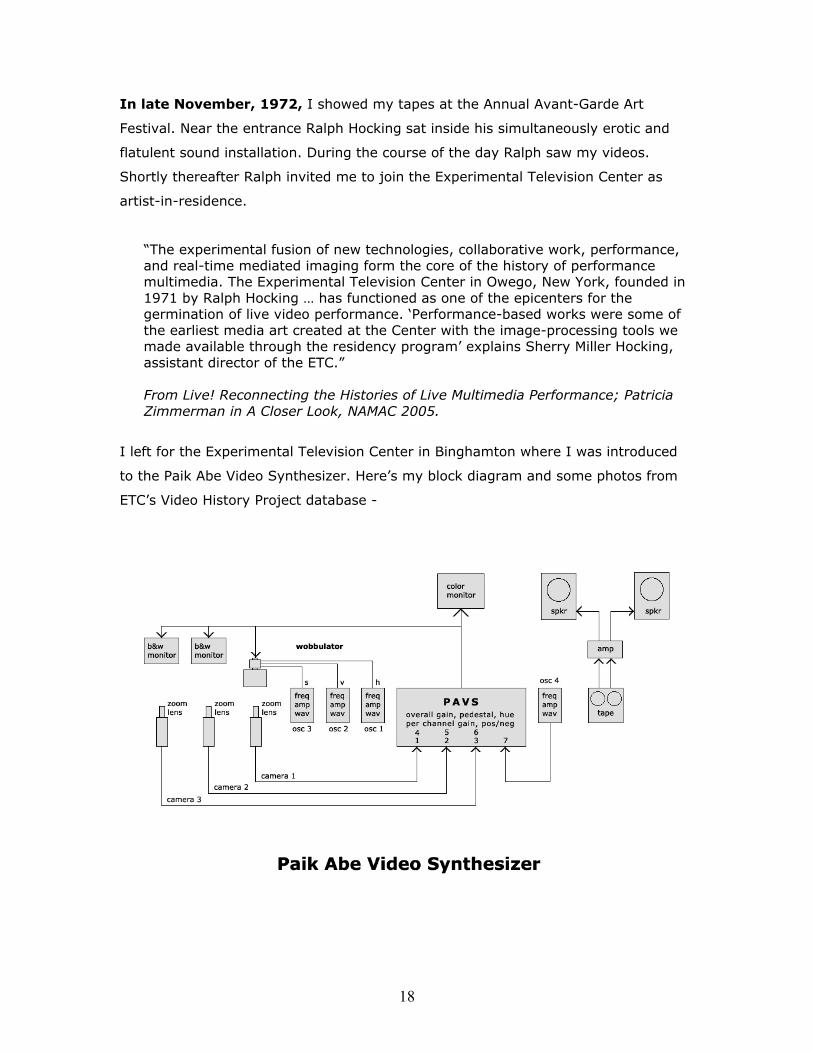
I left for the Experimental Television Center in Binghamton where I was introduced
to the Paik Abe Video Synthesizer. Here’s my block diagram and some photos from
ETC’s Video History Project database -
19
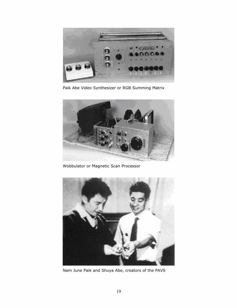
Paik Abe Video Synthesizer or RGB Summing Matrix
Wobbulator or Magnetic Scan Processor
Nam June Paik and Shuya Abe, creators of the PAVS
20
My job was to assist visiting artists including Tom DeWitt, Bill T Jones and Arnie
Zane, John Reilly, Rudi Stern, Ed Melnick and Peer Bode. I also took the Paik Abe on
the road, conducting workshops throughout New York State - for the New York State
Art Teachers Annual Conference, at the Everson Museum in Syracuse, and the
Kitchen in NYC. I loaded the Center’s van with the Paik Abe, b&w cameras and
tripods, b&w monitors, a couple of larger color monitors, oscillators, audio amps, and
tape decks. I would arrive, setup, show tapes from the Center, demonstrate the
synthesizer and the video system, and encouraged people play.
I stayed the following year and continued to conduct workshops in image synthesis
traveling back to the Kitchen and to Global Village in NYC, and York University in
Toronto, Canada. I participated in Astral Projections: A Polyfusion of Media at the
Rochester Planetarium and the Hayden Planetarium in Boston. I assisted artists
including Jeanne Pierre Boyer, Howard Gutstadt, Toby Carey, Lois Welk, Meryl
Blackman, Taka Imura, Carlotta Schoolman, and Doris Chase.
David Jones joined the Center. He maintained the equipment and began researching
gray level keyers. He interfaced a standard video mixer/SEG to a second Paik Abe
Video Synthesizer in the studio.
The Center hosted the Gay Video Workshop, and performances by Richard Landry,
and the American Dance Asylum - Bill T Jones, Lois Welk, and Arnie Zane. We
participated in the Video in New York State Conference at the Whitney Museum in
NYC, and the Video and the Museum Conference at the Everson Museum in
Syracuse.
I was now performing with the Paik Abe.
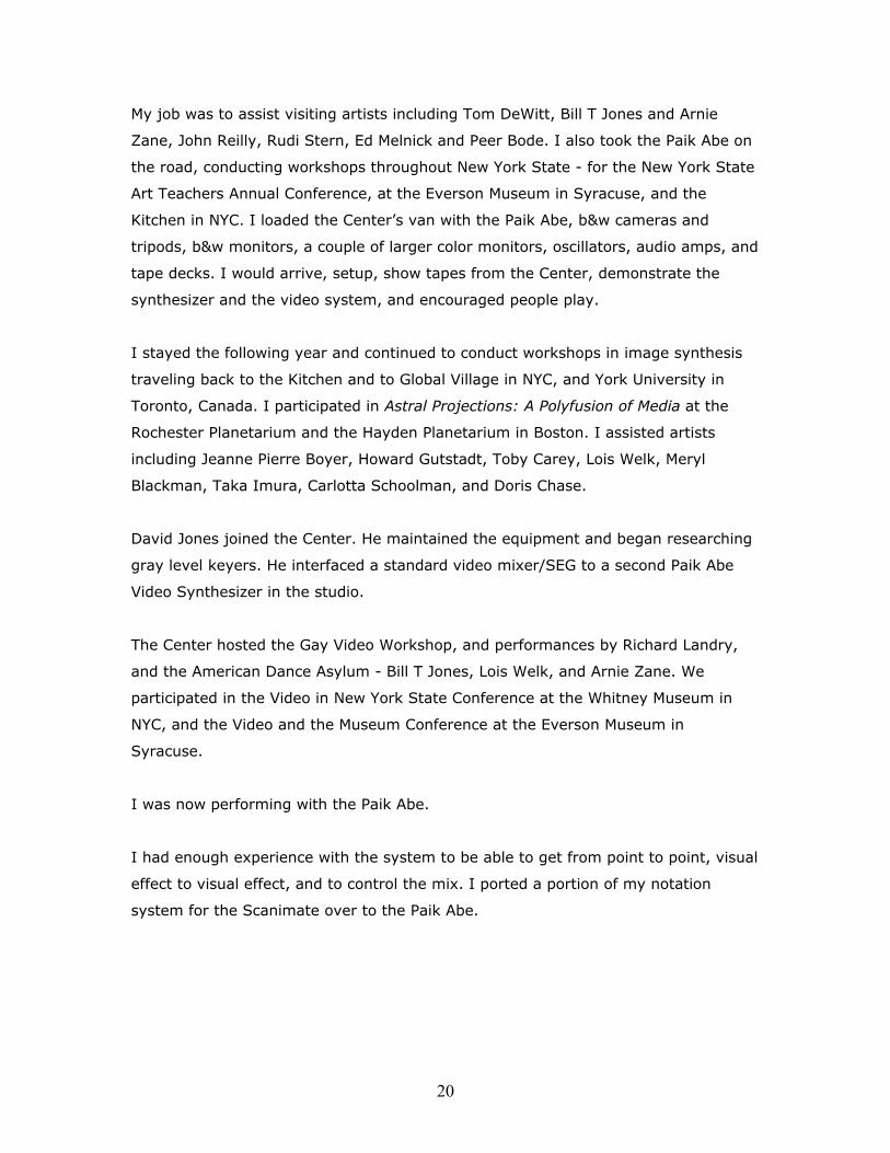
I had enough experience with the system to be able to get from point to point, visual
effect to visual effect, and to control the mix. I ported a portion of my notation
system for the Scanimate over to the Paik Abe.
21
It worked for a stable system. However, the Paik Abe was in a state of constant
development. The colorizer portion or ‘RGB Summing Matrix’ stayed pretty much the
same but the cameras, oscillators, audio amps, monitors, and the wobbulator or
‘Magnetic Scan Processor’ were constantly blowing up, being swapped out, being
modified, and so on. Just changing camera lenses introduced enough variation to
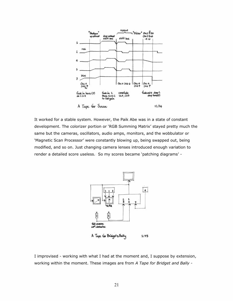
render a detailed score useless. So my scores became ‘patching diagrams’ -
I improvised - working with what I had at the moment and, I suppose by extension,
working within the moment. These images are from A Tape for Bridget and Bally -
22
01 02 03
04 05 06
07 08 09
10 11 12
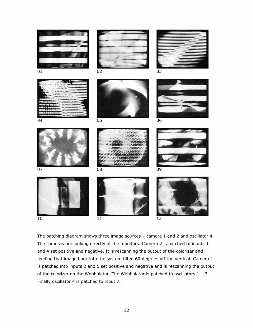
The patching diagram shows three image sources – camera 1 and 2 and oscillator 4.
The cameras are looking directly at the monitors. Camera 2 is patched to inputs 1
and 4 set positive and negative. It is rescanning the output of the colorizer and
feeding that image back into the system tilted 60 degrees off the vertical. Camera 1
is patched into inputs 2 and 5 set positive and negative and is rescanning the output
of the colorizer on the Wobbulator. The Wobbulator is patched to oscillators 1 – 3.
Finally oscillator 4 is patched to input 7.

23
Here’s a brief outline of the ‘score’ - Image 01 - oscillator 4 is generating the three horizontal bars in the image. It appears to be set to a frequency of approximately three times the vertical sync rate or 180 cycles per second (3 x Vsync = 180cps). Its amplitude is all the way up and it appears to be sine wave. The background jumble including the characteristic PAVS ‘s curve’ is from the camera 1. Image 02 – oscillator 4 appears to be fading out. Note that by increasing the oscillator frequency slightly, greater than 180cps, the bars move from top to bottom of the screen and by decreasing the frequency slightly, less than 180cps, the bars reverse direction and move from bottom to top. Image 03 – the frequency of oscillator 4 is reset to a frequency of approximately 1440cps (24 x Vsync = 1440cps). There appears to be a negative image of bars mixed in as well as the ‘s curve’ distortion in the background. Image 04 – the background image is brought up in the mix. It appears that the input gain has ‘wrapped over’, solarizing the input image. A portion of the ‘s curve’ is visible as are other artifacts of the feedback process. Image 05 – the bars are gone for the moment. The remaining image is from camera 1 and the Wobbulator. Light flows through the distorted raster driven by oscillators 1-3. Image 06 – the bars are back at 180cps playing over the Wobbulator. Image 07 – both the bars and camera 1 have been faded down and camera 2 faded up. I have no idea what is generating the squiggles. It could be left from camera 1. It could be light from a window in the studio. Image 08 – the bars are reset to 1440cps playing over camera 2. Note the spiral produced by zooming out the camera lens. The pattern is a variation of image 04. Image 09 – the bars are reset to 180cps and the squiggles return. There may have been a range switch on the oscillator that jumped from 180 to 1440cps and back. If not, the oscillator would have past through all the intermediate settings 4, 5, 6, 7, etc bars per frame. Image 10 – this is probably the Wobbulator with all the oscillators turned down, the horizontal scan reversed, and camera 1 zoomed out. The single vertical bar is oscillator 4 at 15,750cps. Image 11 – the oscillators controlling the Wobbulator are turned on. The tunnel effect is gone and the raster is pulled apart as in image 05. Image 12 – the bars are faded down slightly and camera 2 is faded up. The pattern generated in images 05 and 07 are combined in the final image.
24
Bill T Jones and Arnie Zane arrived at Harpur College in Binghamton about the same
time as I arrived at the Center. Lois Welk moved down from Brockport and the three
of them formed the American Dance Asylum. Peer Bode and Meryl Blackman were
students at Harpur College. Lois had a background in contact improvisation. Bill and
Arnie were more structured. Peer and Meryl were in the film department and tended
towards structure. Together and with others we formed the Center collective.
Perhaps because of the nature of the technology, the soul of the analog machine, I
was less concerned with structure and more concerned with flow – with listening to
the machine. And I had an advantage working with real-time video synthesis. There
was no right way or wrong way to do things - no tradition. There was no map for the
territory. I was free to explore it on my own. My performances were, as a result,
explorations or improvisations based on any number of factors ranging from the
particular equipment configuration to the quality of light and sound in the
performance space.
Years later Ralph said, “The tools available at the Center as well as the medium (itself) amplified the real-time nature of the medium. The first generation of video artists understood that the technology engendered intimacy and immediacy – in the creative actions of the maker and the presentations to the viewer.”
For me it was the immediacy – the instant high of creating images for an audience in
real-time. I was a one-man band.
I remained at the Center for a third year and continued to conduct workshops in
image processing and image synthesis. The NYSCA supported a series of
performances by myself on the Paik Abe Video Synthesizer. More than ten
organizations in New York State and Canada took part including Jamestown Video,
Media Studies at SUNY Buffalo, Portable Channel in Rochester, Synapse in Syracuse,
Woodstock Community Video, the Kitchen, Anthology Film Archives, the SAW
Gallery, A Space, the Musee d’Art Contemporain de Montreal, and the Art Gallery of
Ontario.
I traveled with Jean Pierre Boyer, Wendy Clarke, Ed Emshwiller Taka Imura, Nam
June Paik, Kit Galloway, Gerald O’Grady, Steina and Woody Vasulka, Bill Viola, and
25
the Center’s Paik Abe to Exprmntl 5 Film Festival in Knokke Heist, Belgium where I
demonstrated the video synthesizer.
Back in Binghamton I ran classes in basic and advanced video synthesis and assisted
visiting artists including Gary Hill, Neil Zusman, and Carol Goss.
David Jones developed a voltage controlled video amplifier, voltage controlled video
keyers, and started working on a four-channel voltage controlled colorizer. Don
McArthur developed a digital frame buffer. And David, Don and myself began a
project to explore computer-based imaging and video processing.
In late 1976 The Center and Woodstock Community Video sponsored a series of
multimedia events including performances by Synergism, a multimedia performance
group including Gary Hill and myself, audio and video synthesis, and Sara Cook,
dance.
In an interview with Benton C Bainbridge I said, “I used 4 cameras [with the Paik Abe] and the light from the system was the input to the system. I used the light from the monitors themselves and put stuff in front of the monitors, in front of the cameras. It was basically one person – a one-man band.
“ I had to use prerecorded audio, unless I had someone to play with me. That's why when Gary Hill and I got together - it was a lot of fun. We could switch off. We both knew how to use the Paik Abe and the Jones Colorizer. We both had EMS Synthi-As. We both knew how to use the equipment so we traded off, back and forth.
“The TV Center in Binghamton was not that far from Woodstock. A couple of days a week, I would go down to Woodstock, I would do workshops and hang out with Gary. We did a number of performances with Sara Cook, a dancer. She lived outside Woodstock. The three of us got together and did dance, music and video. We used live cameras. We always had camera people available. It was fun. We performed at the Woodstock Artists Center, at Joyous Lake, in the Woodstock Community Video barn. Gary and I did a weekly cable show. Sara would come over and dance. That worked very well - the audience was out there looking at something different on their TV sets.”
My fourth and final year at the Center, I continued to assist visiting artists. Dave
Jones, Don McArthur and myself participated in the Videofreex Tele-Techno
Conference. The NEA chipped in to fund the computer video interface project that
now included Steina and Woody Vasulka and Jeffrey Schier. Rich Brewster built a
rack of oscillators and control signal generators. David continued to develop voltage
controlled video modules. A commercial video mixer/SEG was integrated into the
26
system and a large 64 x 64 point switching matrix tied everything together. I
participated in Expovision, one final multimedia performance blowout, at Woodstock
Community Television.
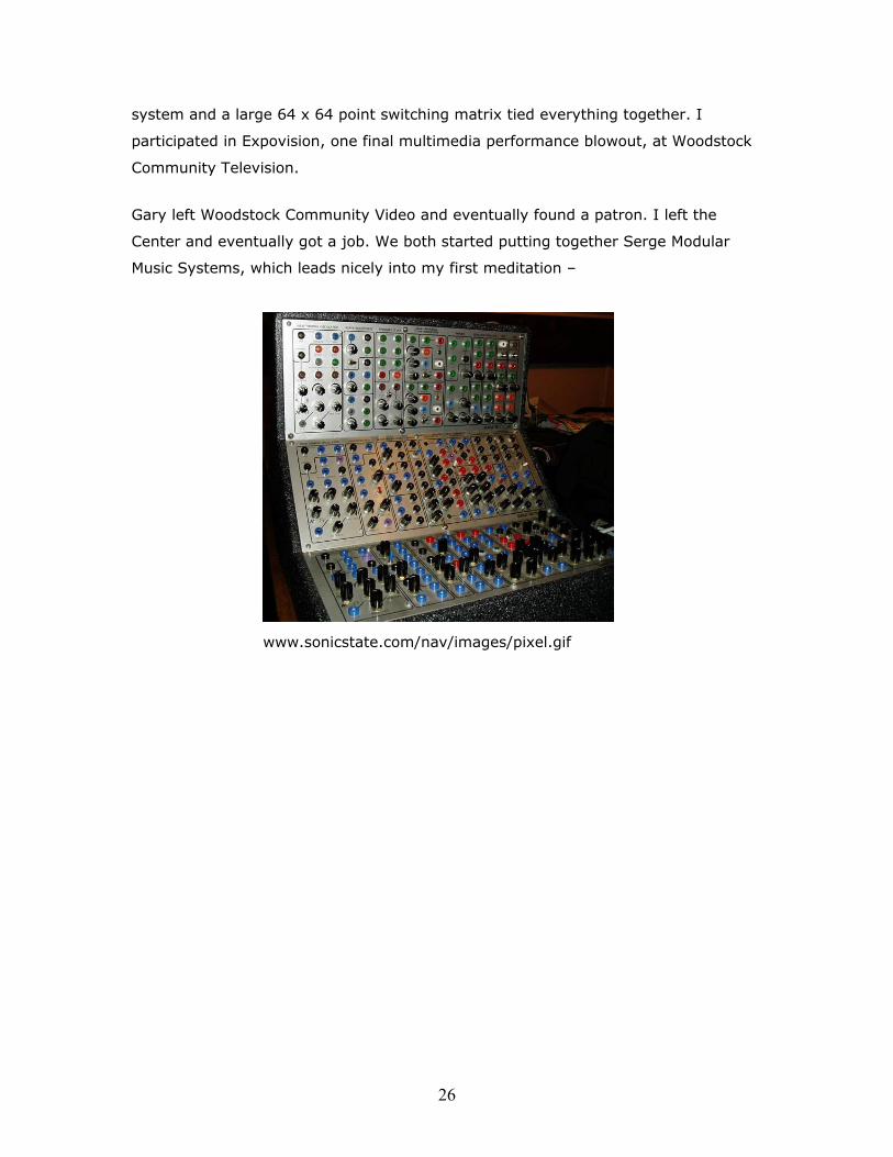
Gary left Woodstock Community Video and eventually found a patron. I left the
Center and eventually got a job. We both started putting together Serge Modular
Music Systems, which leads nicely into my first meditation –
www.sonicstate.com/nav/images/pixel.gif

27
Knob Twiddling
How to play an analog synthesizer.
Sun Ra said that the Moog synthesizer “… will require a different technical approach, touch and otherwise in most efforts of behavior. It is a challenge to the music scene.... The main point concerning the synthesizer is the same as in all other instruments, that is, its capacity for the projection of feeling. This will not be determined in a large degree just by the instrument itself, but always in music, by the musician who plays the instrument.”
My first experience with ‘knob twiddling’ was using the Scanimate analog computer
system. The main control unit allowed the video image to be broken – between raster
lines - into 5 sections. Each section had separate controls for initial and final
position, width, length, depth, axis, and intensity. There were potentiometers to control
the duration of the ramp that ‘moved’ each section from its initial to final settings, to
control oscillator frequency and amplitude, and to mix the red, green, and blue color
components for each section. There were 90 plus potentiometers - with knobs – available
for twiddling.
The position, size and intensity controls were set before animating the image. However
the oscillator controls and various timing and mixing modules could be patched into
the sectioned image in order to modify these settings. A low speed oscillator could be
used to move a sectioned up and down, cause it to ‘squash and stretch’, or fade on and
off. A locked oscillator could be used to bend and distort an image. A special pair of
oscillators – the sine cosine oscillators – could be used to move the image in a circle or
spiral.
As mentioned, normally all these controls were preset and the animation was
triggered to run from start to finish – from initial to final settings. But I used the
28
oscillators to control the image directly. I didn’t run the animation start to finish.
Instead I built the animation in real time using the oscillators and mixing functions
available on the Animation Aid and through the patch panel. In this way – with a
turn or twiddle of any given knob – I could modify the image in response to a change
in the image or in the sound track. Depending on the amount the knob was turned
and on the nature of the ‘effect’ the change in the image could be subtle - or not.
Moving the frequency of an oscillator in and out of phase with vertical or horizontal
sync produced dramatic changes in the image. Adjusting amplitude level produced
smaller changes. Moving the red, green, blue sliders produced subtle color shifts. I
discovered that I could move the image ‘to the beat’ and respond to musical phrases. I
could ‘play along’ with a sound track.
I produced several ‘music videos’ on ½” reel to reel tape including Hendrix, Joplin, Alice
Cooper; Brain Salad Surgery; Central Maine Power; and Paper Shoes.
Perhaps, I was the first VJ.
My second experience with knob twiddling was on the Paik Abe Video Synthesizer - a
much different ‘beast’ from the corporate Scanimate. It was an artists’ machine – built
by an artist for artists – more emotional and less intellectual. The PAVS was about
color - not about counting, positioning and bending raster lines. Rather than the
hard-edged, cartoon color of the Scanimate, it produced gorgeous, electronic watercolor.
The PAVS had gain controls for the 7 video input channels. In addition each channel
had a positive-negative toggle switch. There were controls for overall pedestal and gain
and a large knob to affect the overall hue of the colorizer. An important Paik Abe add-
on was the Wobbulator or ‘magnetic scan processor’. Audio oscillators distorted the
image vertically, horizontally and into a sort of ‘s’ curve. Of course these oscillators
had potentiometers for controlling frequency and amplitude. Some of the oscillators

29
or function generators had switches to select frequency ranges and various
waveforms, and potentiometers to control waveform symmetry. The normal inputs to
the PAVS were black and white video cameras used live or to ‘rescan’ images from
monitors. Each monitor had potentiometers for adjusting brightness and contrast.
Each camera had an adjustable zoom lens and sat on an adjustable tripod.
There were plenty of ‘knobs’ available for twiddling.
All analog circuits and therefore systems are prone to a phenomenon called ‘drift’. The
systems at Computer Image Corporation were turned on at 7am and allowed to ‘warm
up’ for at least 45 minutes. Even though the studio temperature and humidity were
controlled the Scanimate system tended to ‘drift’ away from its set values. The high-
speed oscillators changed frequency on a whim. Traditional animators didn’t
consider this a plus. But I did!
I played these systems in real-time. I played them in situations where conditions were
constantly changing – the temperature, humidity, ambient light, power fluctuations,
and so on. On reflection, I think that drift adds ‘shading’ and character to the output.
I deliberately tuned the oscillators in relation to each other then let them drift. Drift
became shading – it added subtlety and character to the effects. The image lived and
breathed on screen. Sometimes, especially when using feedback, it also gasped and
expired – but this too is ‘life’.
Neither the Scanimate nor the PAVS were ‘all analog’ synthesizers. Being video
systems, they were hybrids. Video sync – counted down from a fixed frequency
crystal – is digital. Vertical sync is always 59.54Hz, horizontal 15.732KHz, and
color burst 3.58Mhz. They also lacked flexibility. Scanimate was designed to do one
thing – animation graphics. The PAVS was a colorizer – a closed system. However, its

30
inputs and outputs could be reconfigured to create more flexibility creating a more
open system.
My first ‘all analog’ system was a Serge Modular Music System. Serge Tcherepnin
designed and built the circuit boards on his kitchen table. He packaged all the parts
for each module and shipped them out as kits. I assembled my own, personal system.
Serge believed that the purpose of the analog synthesizer was to create new sounds –
not to emulate traditional instruments – thus no keyboard.
How does one play the Serge? The answer is obvious - by twiddling knobs and
plugging and unplugging patch cords.
Here’s a quote from the unofficial Serge Modular website, “… Why analog? They [analog synthesizers] have a unique sound that varies from one manufacturer to another. Building new sounds is fun. Patching gives instant feedback (if not instant gratification), and is loaded with the pleasure of twisting smooth knobs and plugging sturdy patch cords. There is never any question of processing power, it always happens in real time. You can go deliberately for effects, or spend hours patching, looking for a magical serendipitous WOW sound. Once the sound is built you can keep tweaking it during play with dozens of knobs, the timbres and tempos becoming wonderful silly putty.”
Serge introduced a key concept in the development of analog instruments – total
modularity. Other modular synthesizers separated sound signals from control
voltages from sync signals. Serge didn’t. Any output could be patched to any input.
He standardized voltage-controlled inputs and outputs so that the sound of one
module could be used to control a second, third or fourth module.
I paired up my voltage-controlled oscillators [VCOs], tuned them in relation to each
other, and let them drift. I tuned my low frequency oscillators [LFOs] to a basic
31
frequency and let them drift. Given that any output could be patched to any input, I
tried a patching the sound output of the second oscillator in a pair back into the
control parameters of the first oscillator – or into the first oscillator of a second pair.
The added an element of unpredictability or risk that coupled with the inevitable drift
really added color and excitement to the resulting sounds. Knob twiddling became a
source of wonder and surprise. Sometimes a simple change would move the whole
performance in a new, unanticipated direction. I considered this to be a good thing. I
added a variable speed tape delay to the mix and was creating minimal ‘techno’ years
before Detroit.
David Jones, the engineer at the Experimental Television Center, developed his own
voltage-controlled video modules including keyers, mixers, a sequencer and a
colorizer. Rich Brewster, his assistant, developed a series of control modules including
oscillators, ramp generators, and mixers.
The ETC video synthesizer system is still running and still has a lot of knobs.
What happened to all those analog systems? Most people never got it - didn’t get the
drift. They attached keyboards to their systems and expected them to behave like
traditional instruments. But think about it … what is it that colors the sound of a
traditional instrument like a flute or a guitar? They ‘drift’. They go out of tune.
Varying finger pressure or the breath adds shading to a note. The keyboard created a
false expectation. An analog synthesizer isn’t a mechanical instrument like a piano
or an electro-mechanical instrument like an organ. It’s a living-breathing box of
circuits. Unfortunately as soon as the novelty had worn off, the traditional music
programs at schools and universities moved the analog synthesizers into a closet and
went back to doing things the way they always had ...

32
This page intentionally left blank.
33
In 1978 Ron Pelligrino wrote,
“Imagine discovering an instrument that is modeled on the flow of life; that can serve as a direct extension, radiator, and articulator of a composer’s view; that embodies the collective thoughts of visualization; that beams energy to the composer’s center which transforms and reflects it into unique and ephemeral forms analogous to that center’s perspective, biases, inclinations and tendencies. Imagine that instrument. It is an electronic wave instrument, a synthesizer by whatever name it is called – Sal-Mar, Buchla, Synthi, Pinzarrone, Beck, Moog, Sekon, Tcherepnin – they all produce electric waves which offer a synthesis of perspectives, a virtual history of science and art to the real-time composer /performer who needs to continue his song and dance.” Contact Quarterly Vol III No 3/4, Spring/Summer, 1978
As I said, most people never got it, but some did.

34
This page intentionally left blank.