multirotor sizing methodology with flight time estimation
TRANSCRIPT

HAL Id: hal-02504788https://hal-centralesupelec.archives-ouvertes.fr/hal-02504788
Submitted on 11 Mar 2020
HAL is a multi-disciplinary open accessarchive for the deposit and dissemination of sci-entific research documents, whether they are pub-lished or not. The documents may come fromteaching and research institutions in France orabroad, or from public or private research centers.
L’archive ouverte pluridisciplinaire HAL, estdestinée au dépôt et à la diffusion de documentsscientifiques de niveau recherche, publiés ou non,émanant des établissements d’enseignement et derecherche français ou étrangers, des laboratoirespublics ou privés.
Multirotor Sizing Methodology with Flight TimeEstimation
Marcin Biczyski, Rabia Sehab, James Whidborne, Guillaume Krebs, PatrickLuk
To cite this version:Marcin Biczyski, Rabia Sehab, James Whidborne, Guillaume Krebs, Patrick Luk. Multirotor SizingMethodology with Flight Time Estimation. Journal of Advanced Transportation, Hindawi PublishingCorporation, 2020, 2020, pp.9689604. �10.1155/2020/9689604�. �hal-02504788�

Journal of Advanced Transportation123Multirotor Sizing Methodology with Flight Time4
Estimation5
Marcin Biczyski1, Rabia Sehab1, James F. Whidborne2, Guillaume Krebs3 and6
Patrick Luk47
1On-board Energies and Systems Division, ESTACA Campus West, 53000 Laval, France82Centre for Aeronautics, Cranfield University, MK43 0AL Cranfield, UK9
3Pôle "Systèmes" ECo2, GeePs - CentraleSupelec, 91192 Gif sur Yvette, France104Centre for Thermal Energy Systems and Materials, Cranfield University, MK43 0AL Cranfield, UK11
Correspondence should be addressed to Marcin Biczyski: [email protected]
Abstract13
This paper addresses the need for sizing of rotors for multirotor vehicle applications such as14personal air transport, delivery, surveillance and photography. A methodology for the propeller15and motor selection is developed and augmented with flight time estimation capabilities. Being16multirotor-specific it makes use of the platform’s simplicity to rapidly provide a set of off-17the-shelf components ready to be used in the vehicle. Use of operating points makes the18comparison process fast, precise and tailored to specific application. The method is easily19implemented in software to provide an automated tool. Furthermore, clearly defined input and20output parameters make it also usable as a module in other multicriteria optimisation algorithms.21The new methodology is validated through comparison with consumer-grade drone and the22calculated results are compliant with manufacturer’s specification in terms of maximum hover23time.24
Keywords— BLDC, Multirotor, PAV, Propeller, Sizing, UAV25
1 Introduction26
In recent years Unmanned Aerial Vehicles (UAVs), have become a popular solution for a variety of27civil and military applications including surveillance, photo- and videography and land surveying.28The versatility of these systems has even found them in many non-standard purposes such as29automated package delivery or Personal Air Vehicles (PAVs). Multirotor UAV platforms have30gained particular attention due to their Vertical Take Off and Landing (VTOL) capabilities as well as31their simple construction and control. Of paramount importance is safety and reliability, especially32when it comes to autonomous solutions, and so the enterprise market offers complete, closed drone33solutions at different size/weight points. These are simple-to-use systems with high degree of user34support and good performance for most applications. However, the mechanical simplicity of the35platform means that customized and open solutions should be available for specialized applications.36Furthermore, the main limitation of multirotor systems is their flight time, mostly due to battery37
1

weight and energy storage constraints. Therefore, a set of tools needs to be created that can aid the38design of customized solutions that can be specifically tailored for a particular application. Thus39there is a need for a methodology to automatically select the best consumer-grade components to40build a custom solution at a given weight and performance level.41
There are few methodologies in the open literature for this purpose; and none lead directly to a42“bill-of-materials” level solution. The most popular approach to obtaining a “flyable” configuration43seems to be to test various motor + propeller combinations and choose one that suits the application44([1]). Although popular with hobbyists, the method has little value in the commercial or research45environment due to high cost (purchase of components), time requirement and the need for specialized46equipment (thrust stand, dynamometer). This method provides the most accurate results, but the47number of combinations needed to be tested increases geometrically with each added component.48This process can be significantly sped up using calculators such as Drive Calculator [2] and eCalc [3],49which incorporate some of the data in their databases, but still the selection needs to be performed50manually.51
Although not solving the problem completely, there are several methods that help with the52preliminary multirotor design. Basset et al. [4] present past and current efforts to develop UAV53pre-sizing methodologies. They focus on conceptual, as well as numerical aspects of the vehicle.54Due to the confidential nature of the projects, the paper does not go into much detail of the inner55working of the methodologies. However, most of them share a trait of being as general as possible56in order to make them applicable to every configuration, which is not desired when dealing with57an already chosen topology, such as multirotor, due to possible oversimplification and loss of58optimisation opportunities.59
Multirotor-specific methodologies were developed by Gatti and Giulietti [5], Gatti [6] and60Kim et al. [7]. They all use statistical methods to estimate relations between different components61of the propulsion chain. The first two use analytical methods from the area of aerospace to62calculate take-off weight based on mission requirements, and the last manages to simplify the drone63propulsion model to one equation that allows to obtain power or thrust generated. Unfortunately,64these approaches provide too little data to properly size the components, and in some cases even65require the data of a selected component to work. Therefore, while useful for calculating the target66multirotor weight for the application, they cannot be used for the component selection process.67
This paper presents a method for sizing of the multirotor propulsion system through the68selection of propeller and motor. Furthermore, the method provides the necessary data for the69selection of the Electronic Speed Controller (ESC) and battery. Additionally, it gives a way of70comparing different configurations through estimation of flight time by modelling battery discharge71at constant power requirement. The key point of the methodology is the fact that it works on real72components (propellers and motors) increasing the precision of the estimation. Another feature is73the ability for the selection process to be automated making it an useful module for use in novel74optimisation algorithms. It should be noted that the resultant configuration is based on estimations,75assumptions and inaccurate data, and therefore not optimal, so the methodology results should be76treated only as a good first guess.77
The paper is structured as follows; Section 2 details all the elements of the multirotor78propulsion chain and their interaction; Section 3 describes the methodology based on the inverted79model from the previous section; Section 4 presents example results for a small drone such as DJI80Phantom 4 V2.0 and extends the findings onto Personal Air Vehicles; finally, Section 5 concludes81the paper and highlights the most important outcomes.82
2

2 Multirotor propulsion chain83
Multirotors as a category of flying vehicles cover a lot of variants differing not only in the number84of rotors, but also their placement. Currently, the most popular configuration seems to be quad X85with 4 rotors placed diagonally from the centre, as shown in Figure 1. One of the characteristic86properties of most multirotors is their symmetry and the fact that every arm is the same, except for87rotor spinning direction. This makes it easy to analyse the propulsion system for the general case by88analysing only one arm (one propulsion chain). The Flight Controller (FC) is responsible for control89strategy for the whole platform and preparing a set point for each arm, but it does not participate in90the propulsion chain as such.91
Figure 1: Multirotor in quad X configuration with visible components of the propulsion chain. (i)Flight Controller, (ii) ESC (under arm), (iii) BLDC Motor, (iv) propeller, (v) battery connector.
In most cases Brushless DC (BLDC)motors are used for multirotor propulsion, but sometimes,92usually for toys under 100 g, DC motors are also used. This paper focuses only on BLDC, however93most concepts shown apply to both types. Brushless motors do not have physical brushes, so they94require Electronic Speed Controllers (ESC) to achieve electronic commutation. Therefore the main95components of the propulsion chain are identified to be: propeller, motor, ESC and battery. A96schematic of the propulsion model of a multirotor is shown in Figure 2. It can be seen that there is97one input of a set point (given by FC) and one output, namely the thrust generated by the propeller.98Therefore, the propulsion chain can be identified as a open-loop Single Input Single Output (SISO)99system, which makes it relatively easy to size components one at a time. In the next part of this100section, each component will be described in detail.101
3

,ESC
,battery
,motor ,propellerset point
current
current torque
speedthrust
Figure 2: Multirotor propulsion chain diagram.
2.1 Propeller102
Aircraft propellers are characterized by 3 main parameters: diameter, pitch and the number of blades.103Generally the higher they are, the higher thrust is generated, but also higher torque is exerted on the104motor. However, long, slowly-spinning, 2-bladed propellers are known to be more aerodynamically105efficient than small, fast-spinning, multi-bladed ones. Propeller characteristics are mainly a function106of its rotational speed and the speed of incoming air. However, if we consider air density to be107constant and the air to be static (drone flight speed of 0), the thrust, torque and power depend only on108propeller speed. Additionally, there are secondary parameters such as mass and geometry template109expressed as manufacturing series (e.g. Multirotor, Slow Flyer, Carbon, etc.).110
2.2 Motor111
In a multirotor, the motor’s main objective is to drive the propeller reliably and with high acceleration,112so the speed can be changed quickly. The main limitations of a BLDC motor are in terms of speed113and current. Maximum current is often stated by the manufacturer and maximum speed in no-load114conditions ω0 can be calculated from the KV parameter multiplied by the applied voltage V :115
ω0 = KV × V . (1)116
With a constant voltage, when current is applied, the motor starts exerting torque on the117shaft accelerating it until its torque equals the load torque, assuming the mechanical losses are118neglected. At low speed - far from the motor constraints, it is assumed that the relation between119motor torque and current is constant and expressed with motor torque constant (KT ). Therefore, the120applied current is transformed into the torque based on the motor characteristic, then the torque is121transformed into speed based on the propeller torque-speed characteristic, and finally the speed is122transformed into thrust using the propeller thrust-speed characteristic. This sequence makes the123propulsion chain easy to calculate analytically as a SISO system.124
2.3 Electronic Speed Controller125
Although Electronic Speed Controllers (ESCs) serve a very important purpose in the real-life126multirotor, in the propulsion chain model it has very little importance. In the model, its function is127reduced to transferring current from the battery to the motor under constant voltage. However, when128
4

designing a multirotor, ESC still needs to be sized according to the maximum current flowing to the129motor.130
2.4 Battery131
When it comes to lightweight aerial vehicles, Lithium Polymer (LiPo) batteries currently dominate132the market due to their high energy density and high current discharge capabilities [6], [8]. These133batteries are composed of several cells connected in series (rarely in parallel). Cell voltage changes134according to the state of charge with 4.2 V being at 100%, 3.85 V at 50% and 3.7 V (nominal)135at 20%. However, discharging a LiPo cell under 3 V leads to permanent damage to the battery.136Therefore, it is recommended to only discharge the batteries to about 20%, which grants a Depth of137Discharge (DoD) of 80%. The cells can be connected in series or in parallel, denoted by S or P138respectively, so for example, 4S1P is a 4 cell battery with 14.8 V nominal voltage. Additionally,139the batteries are characterized by their capacity in mAh and a C-rating (rC), which specifies the140maximum current that can be drawn continuously, for example 35C× 5.2Ah = 182A (the unit being141C and not Coulomb). It is evident that maximum discharge current is not dependent on battery142capacity.143
3 Sizing methodology144
By inverting the propulsion system model developed in the previous section, a new model can145be obtained allowing to estimate battery voltage based on thrust generated, as shown in Figure1463. This allows for an iterative approach in order to determine the time required to deplete the147battery at constant power draw, which effectively serves as a flight time estimate. Thus, two distinct148sub-systems can be distinguished in the system model: the actuating system and the power system.149This manifests itself in the sizing methodology, which is also divided into two parts. Figure 4 shows150a simplified view of the methodology.. Although it is based on the diagram in Figure 3, it also shows151the separation between battery sizing and battery simulation (flight time simulation).152
,ESC
,battery
,motor ,propeller
current
current torque
speedthrust
Figure 3: Inverted multirotor propulsion chain diagram.
3.1 Actuating system153
The actuating system provides the thrust propulsion to the vehicle and consists of the propeller, the154motor, an ESC to control the motor and a battery to power the motor. The propeller sizing and155
5

,propellerselection,
motorselection
,ESC & battery
sizing
,flight timeestimation
,selectedpropeller,
selectedmotor
,ESC & batteryspecifications
,flight timeestimate
,input
torque
speed
motor power& current
propellerdata
motordata
max. current,battery C-rating
batterydischarge time
total weight,sizing requirements
POWER SYSTEM ACTUATING SYSTEM
Figure 4: Simplified sizing methodology flowchart with division into two sub-systems.
selection is performed first, the motor sizing being dependent on the propeller properties. Finally,156specifications for the ESC and the battery are produced.157
The propulsion system model used here is only applicable in static conditions and at158constant speed. Modelling a multirotor in flight is much more complicated due to the presence of159aerodynamic effects such as variable angle of attack, reduction of thrust coefficient with advance160ratio and additional frame drag. However, an approximation of the required performance for full161controllability in flight is made using the model only in static conditions of operation. It uses a state162of equilibrium achieved at hover (in no-wind conditions), where thrust generated by the propellers is163equal to the multirotor’s weight. This thrust can be multiplied by a constant thrust-to-weight ratio164to achieve a value of static thrust that guarantees specific performance in the air depending on the165application. This approach appears imprecise, however, during the years of use of similar methods166in the community of radio controlled aircraft modellers, the values of thrust-to-weight ratio required167for different applications have been validated with many test flights. A quick summary of typical168values can be found in Table 1, which is based on [9] and [10]. Additionally, in static conditions169there is no influence of rotor inertia on motor performance, so the propeller and motor selection can170be decoupled, further simplifying the process.171
6

Table 1: Typical applications for multirotors of different thrust-to-weight ratios.Thrust-to-weight ratio Application
2 slow flight (minimum)3 payload transport; photography4 surveillance5+ aerobatics; high-speed video7+ racing
3.1.1 Propeller sizing and selection172
The propeller sizing and selection process starts by defining a propeller database represented as a173set of available propellers174
P := {pi : i = 1 . . . np} (2)175
where the ith propeller pi is defined by the pair176
pi := (fpi, gpi) (3)177
where fpi denotes the ith propeller performance, which will be defined later, and gpi denotes its178physical properties expressed as a 4-tuple179
gpi := (di, θpi,mpi, sni) (4)180
where di is the ith propeller diameter, θpi is its pitch angle, mpi is its mass and sni is a discrete181parameter representing the propeller series name. The propeller set P is then filtered to obtain a set182of propellers Pp ⊆ P that satisfy a requirement 4-tuple183
gpr =(dmin, dmax,mpmax,Snr
)(5)184
where dmin is the minimum diameter, dmax is the maximum diameter, mpmax is the maximum mass,185and Snr is a set of preferred series names186
Snr := {snk : k = 1 . . . ns}. (6)187
Thus188
Pp ={pi : di ∈ [dmin, dmax] ,mpi ∈ (0,mpmax], sni ∈ Snr
}. (7)189
This helps save time when evaluating the performance data and calculating operating points that is190done next.191
The performance of the ith propeller fpi is denoted as a triplet of bijective mappings192
fpi :=(ω 7→ T(ω), ω 7→ τ(ω), ω 7→ Pp(ω)
)(8)193
where ω is the rotor speed, T is the thrust, τ is the torque and Pp is the propeller power. Let194
T (k)r denote a required thrust. For each pi ∈ Pp, we determine a set of no operating points195
opi ={o(k)pi : k = 1 . . . no
}where196
o(k)pi := (T (k)i , ω(k)i , τ
(k)i , P(k)pi ) (9)197
7
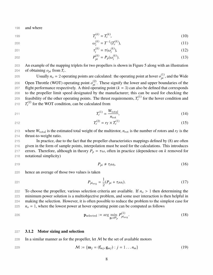
and where198
T (k)i = T (k)r , (10)199
ω(k)i = T−1(T (k)r ), (11)200
τ(k)i = τ(ω
(k)i ), (12)201
P(k)pi = Pp(ω(k)i ). (13)202
An example of the mapping triplets for two propellers is shown in Figure 5 along with an illustration203of obtaining opi from Tr .204
Usually no = 2 operating points are calculated: the operating point at hover o(1)pi , and the Wide205
Open Throttle (WOT) operating point o(2)pi . These signify the lower and upper boundaries of the206flight performance respectively. A third operating point (k = 3) can also be defined that corresponds207to the propeller limit speed designated by the manufacturer; this can be used for checking the208feasibility of the other operating points. The thrust requirements, T (1)r for the hover condition and209T (2)r for the WOT condition, can be calculated from210
T (1)r =Wtotal
nrot, (14)211
T (2)r = rT × T (1)r (15)212
where Wtotal is the estimated total weight of the multirotor, nrot is the number of rotors and rT is the213thrust-to-weight ratio.214
In practice, due to the fact that the propeller characteristics mappings defined by (8) are often215given in the form of sample points, interpolation must be used for the calculations. This introduces216errors. Therefore, although in theory Pp = τω, often in practice (dependence on k removed for217notational simplicity)218
Ppi , τiωi, (16)219
hence an average of those two values is taken220
Ppiavg =1
2(Ppi + τiωi). (17)221
To choose the propeller, various selection criteria are available. If no > 1 then determining the222minimum power solution is a multiobjective problem, and some user interaction is then helpful in223making the selection. However, it is often possible to reduce the problem to the simplest case for224no = 1, where the lowest power at hover operating point can be computed as follows225
pselected := arg minpi∈Pp
P(1)piavg. (18)226
3.1.2 Motor sizing and selection227
In a similar manner as for the propeller, letM be the set of available motors228
M := {m j = (fmj, gmj) : j = 1 . . . nm} (19)229
8

Figure 5: Example of obtaining a propeller operating point based on required thrust. a) Obtainingspeed from required thrust. b) Obtaining torque from speed calculated in a). c) Obtaining powerfrom speed calculated in a).
where fmj is the motor model described by the triplet of mappings230
fmj := (I 7→ Pm(I), I 7→ Pe(I), (Pm, Pe) 7→ η(Pm, Pe)) (20)231
where I is the current, Pm is the mechanical power, Pe is the electrical power, η is the efficiency and232where gmj denotes the motor properties expressed as a pair233
gmj := (Imaxj, ω0 j,mmj) (21)234
where Imaxj is the maximum allowable ith motor current, ω0 j is its maximum no-load speed and235mm is its mass.236
Unlike the process for the propeller selection, the performances of the motors must be237evaluated first. The required motor power is set to be Pr = P(k)pselected . Then for each m j ∈ M, we238determine no motor operating point triplets239
o(k)mj := (I(k)j , P(k)e j , η
(k)j ) (22)240
where (dependence on k removed for simplicity)241
I j = P−1m (Pr), (23)242
Pe j = Pe(I j), (24)243
η j = η(Pr, Pe j). (25)244
It should be noted that themapping I 7→ Pm(I) is not bijective in terms of motor characteristics,245because at high current values most of the energy is dissipated as heat. However, considering the246
9

domain only up to the maximum current specified by manufacturer, the function is almost always247monotonic. Therefore, in practice, over the domain [0; Imaxj ] the inverse of power function P−1m can248almost always be evaluated.249
Knowledge of omj for allm j ∈ M allows for filtering of the motor set in regards to maximum250current, speed and mass, thus obtainingMp ⊆ M that satisfies maximum current requirement on251each motor I j ≤ Imaxj and a requirement pair252
gmr =(ωmax,mmmax
)(26)253
where ωmax = ω(2)selected
is the propeller speed at WOT and mmmax is the maximum motor mass.254Thus255
Mp ={m j : I j ≤ Imaxj, ω0 j ≥ ωmax,mmj ≤ mmmax
}. (27)256
Like in the propeller’s case, various selection criteria could be used to choose the motor. In257the simple example for no = 1 it could be the lowest electrical power258
mselected := arg minmj∈Mp
P(1)e j . (28)259
3.1.3 ESC and battery sizing260
The Electronic Speed Controller is sized mainly in regards to the maximum current it can handle.261As it is assumed that the multirotor will never need more thrust than achieved at WOT operating262point, the current should also not go over the calculated value. Therefore, it can be said that263
IESC = I(2)selected
(29)264
where IESC is the rated (maximal) ESC current and I(2)selected
is the motor current at WOT operating265point.266
A substantial part of battery specification needs to be provided by the user to realise flight267time estimation as described in the Subsection 3.2. However, the methodology allows to complete268the battery specification by sizing the C-rating parameter269
rC =IESC × nrot
C(30)270
where rC is the minimal required battery C-rating and C is the battery capacity.271The whole actuating system sizing methodology is depicted by the data flow chart shown in272
Figure 6. It shows the dependence of motor sizing on propeller specification and ESC and battery273sizing on motor specification. The light cyan blocks correspond to the methodology stages, the dark274blue blocks show requirements and constraints and the orange ellipses signify points of database275access. The output data in green ellipses includes specification parameters for sizing all of the276major components of the propulsion system (namely propeller, motor, ESC and battery) and the277calculated propeller and motor operating points that can be used for calculating additional data, such278as estimated flight time. The data corresponding to each of the outputs can be found in Table 2.279
In figure 6 a substantial impact of estimated total drone weight can be also seen - it is used to280calculate required thrust Tr that plays a key role in selecting the propeller, and consequently the281
10

,create propellerdatabase set
,filter propellerset using (7),
define propellerrequirement
,
determine propelleroperation pointsusing (10)–(13),
calculate thrustrequirement using
(14) & (15)
,select propeller
using (18)
,selectedpropeller
,create motordatabase set
,
determine motoroperation pointsusing (23)–(25)
,filter motor
set using (27) ,define motorrequirement
,select motorusing (28) ,
size ESC and batteryusing (29) & (30)
,selectedmotor ,
ESC & batteryspecifications
P
gpr
Pp
Tr
Pp
{opi
}
M
Ppselected
Pr
pselected
M{omj
}gmr
Mp
{omj
}
mselected
omselected
IESC rc
Figure 6: Actuating system sizing methodology information flow diagram.
Table 2: Data contained in sizing methodology outputsOutput name Data contained
Propeller specification name; diameter d; pitch θp; series sn
Motor specification name; KV rating; rated speed ω(2)selected
;rated torque τ(2)
selected; rated mech. power P(2)mselected
;rated el. power P(2)eselected; rated efficiency η(2)
selected;
nominal voltage VESC specification maximum current IESC
Battery specification cell number nC; minimum C rating rC; capacity C
motor. Due to the discrete nature of propeller and motor parameters, the relationship is highly282nonlinear, so it needs to be analysed numerically. However, it is easy to implement the methodology283in a loop to plot the characteristics of flight time versus weight, which may be used in a payload284sizing application.285
3.2 Power system286
The power system section of the methodology focuses on flight time estimation by modelling the287battery. The model is based on the iterative approach presented by Traub [11]. It features 2 important288
11
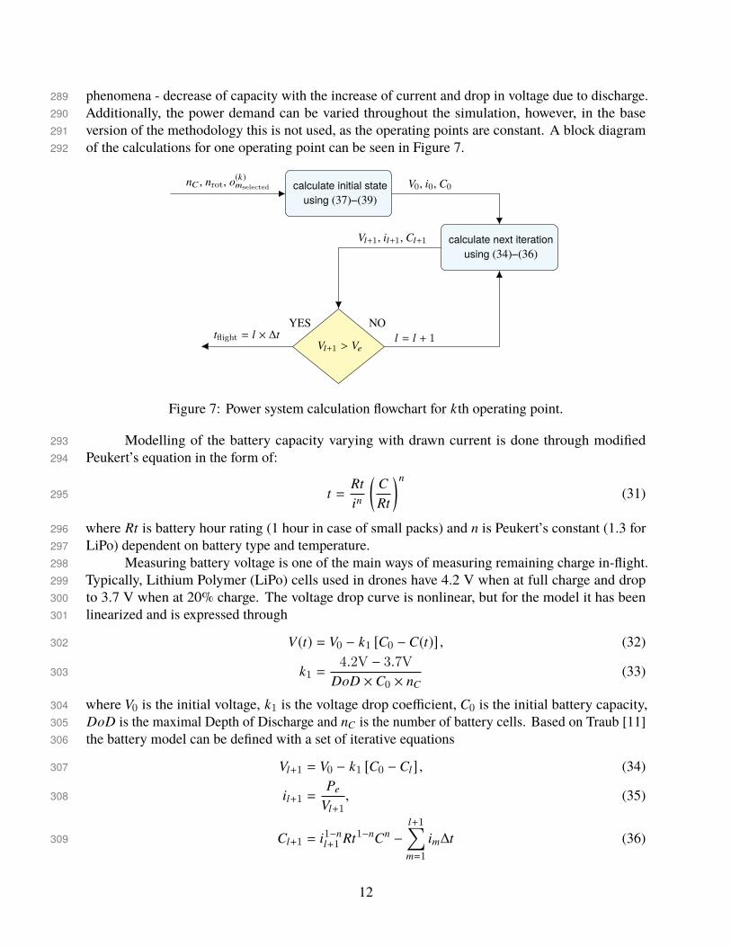
phenomena - decrease of capacity with the increase of current and drop in voltage due to discharge.289Additionally, the power demand can be varied throughout the simulation, however, in the base290version of the methodology this is not used, as the operating points are constant. A block diagram291of the calculations for one operating point can be seen in Figure 7.292
,calculate initial stateusing (37)–(39)
,calculate next iteration
using (34)–(36)
,Vl+1 > Ve
V0, i0, C0
Vl+1, il+1, Cl+1
l = l + 1tflight = l × ∆t
nC , nrot, o(k)mselected
NOYES
Figure 7: Power system calculation flowchart for kth operating point.
Modelling of the battery capacity varying with drawn current is done through modified293Peukert’s equation in the form of:294
t =Rtin
(CRt
)n
(31)295
where Rt is battery hour rating (1 hour in case of small packs) and n is Peukert’s constant (1.3 for296LiPo) dependent on battery type and temperature.297
Measuring battery voltage is one of the main ways of measuring remaining charge in-flight.298Typically, Lithium Polymer (LiPo) cells used in drones have 4.2 V when at full charge and drop299to 3.7 V when at 20% charge. The voltage drop curve is nonlinear, but for the model it has been300linearized and is expressed through301
V(t) = V0 − k1 [C0 − C(t)] , (32)302
k1 =4.2V − 3.7V
DoD × C0 × nC(33)303
where V0 is the initial voltage, k1 is the voltage drop coefficient, C0 is the initial battery capacity,304DoD is the maximal Depth of Discharge and nC is the number of battery cells. Based on Traub [11]305the battery model can be defined with a set of iterative equations306
Vl+1 = V0 − k1 [C0 − Cl] , (34)307
il+1 =Pe
Vl+1, (35)308
Cl+1 = i1−nl+1 Rt1−nCn −
l+1∑m=1
im∆t (36)309
12

with the initial state defined as310
V0 = 4.2V × nC, (37)311
i0 =Pe
V0, (38)312
C0 = i1−n0 Rt1−nCn. (39)313
The information flow in the model is visualized in Figure 7.314As time passes, the voltage decreases, therefore increasing current draw to achieve the same315
power, and consecutively decreasing available battery capacity due to Peukert’s effect, as can be316seen in Figure 8. The simulation is stopped when voltage reaches317
Ve = 3.7V × nC (40)318
or when capacity reaches 20% of initial capacity (only works when power drawn is constant). The319output is simply the simulation time, calculated as the product of the time step value and the number320of iterations.321
Figure 8: Example battery behaviour during hover.
4 Example results322
Themethodology presented has been implemented as aMATLAB script. This allows to easily process323large quantities of data from propeller and motor databases and to plot component characteristics on324every stage of the selection process.325
13

In this example, performance data published by APC Propellers [12] will be used for the326propeller database. It contains static and dynamic performance obtained through analytical methods327of all products currently manufactured by the company. Due to the reliance on external computer328software, airfoil drag (and consequently, torque) may be under-predicted at low speeds. Additionally,329wind tunnel measurements of selected propellers [13] show over-prediction of thrust coefficient (and330consequently, thrust) of around 12% on average across all tested propellers. Detailed results are331shown in Table 3 and in Figure 9. Therefore, an easily adjustable parameter called Safety Factor332(SF) was introduced that increases required power at the WOT operating point to reduce the impact333of mentioned inaccuracies and guarantee that the chosen motor will be able to reach the expected334speed335
I(2)j = P−1m (Pr × SF), (41)336
η(2)j = η(Pr × SF, Pe j). (42)337
There is no need to include Safety Factor in the ESC sizing, as the WOT operating point at which it338is sized, in typical operating conditions, is achieved only for a few seconds at a time, not enough to339damage the unit. The inclusion of the Safety Factor parameter in the battery sizing is recommended,340as LiPo batteries are prone to ageing, which increases their internal resistance. Hence, with time at341high currents more and more heat is generated, eventually leading to battery damage. What is more,342cheap batteries are known for parameters varying between each unit, further justifying the need for343an additional safety measure. Therefore, Equation (30) becomes344
rC =IESC × nrot × SF
C. (43)345
Table 3: Errors between measured and simulated propeller characteristics - thrust coefficient (CT )and power coefficient (CP).
Mean CT error -0.0121Mean relative CT error -12.6306%Mean std. deviation of CT 0.0051Mean CP error 0.0059Mean relative CP error 2.4816%Mean std. deviation of CP 0.0022
For the motor database, a database bundled with Drive Calculator [2] software was used. It is346based on measurements done and uploaded by its users, so it is impossible to accurately measure the347discrepancies with real products, but they are estimated to be around 5-10% overall. However, a348significant inaccuracy is introduced with the simplified motor model used to calculate characteristics349based on scarce data. The model, applicable both to BLDC and DC motors, considers only two350sources of losses: copper losses, calculated using winding resistance351
PCu = RmI2motor (44)352
and iron losses, calculated using no-load current353
Piron = V × I0 (45)354
14

Figure 9: Relative errors between measured and simulated propeller coefficients.
where PCu are copper losses, Rm is the windings resistance, Imotor is the current delivered to motor355windings, Piron are iron losses, V is the nominal voltage and I0 is the no-load current. As the356no-load measurement is usually done through an ESC, the iron losses also incorporate losses from357the controller. The model, based on [14], is calculated as follows:358
Pprop = τprop × ωprop × SF, (46)359
Imotor =V −
√V2 − 4Rm(Piron + Pprop)
2Rm, (47)360
Pmotor = V × Imotor, (48)361
ηmotor =Pprop
Pmotor× 100% (49)362
where Pprop - is the power delivered to the propeller, τprop is the propeller torque, ωprop is the363propeller speed, Pmotor is the motor electrical power and ηmotor is the motor efficiency.364
To demonstrate the capabilities of the methodology a set of example results is presented365for a low-weight drone. The results are validated against a similar commercial product. Based366on the findings, a hypothetical usage of the methodology for sizing of Personal Air Vehicles is367demonstrated.368
4.1 Small drone369
For the ease of validation, the input parameters of the methodology were set to match those of the DJI370Phantom 4 Pro V2.0, as indicated in Table 4. This enables easy comparison of the vehicle’s published371
15

specification [15] with the sizing method’s results in terms of flight time and propeller dimensions, as372the manufacturer does not provide motor data. It should be noted here that the Phantom 4 uses LiHV373(High Voltage LiPo) batteries rated at 3.8 V per cell, however in the calculations the more popular374LiPo batteries, rated at 3.7 V per cell, are used. Additionally, V2.0 uses FOC-enabled drivers, which375generate sinusoidal signals instead of the usual trapezoidal. However, the manufacturer advertises it376as a means to reduce noise instead of improving performance, so it can be assumed that in this case377the difference can be neglected.378
Table 4: Basic DJI Phantom 4 V2.0 parameters.Number of rotors 4Diagonal size 350 mmTotal weight 1375 gBattery weight 468 gBattery capacity 5870 mAhBattery nominal voltage 15.2 VBattery type LiHV 4SPropeller diameter 9 inchPropeller pitch 5.5 inch
Table 5: Additional methodology parameters used in small drone sizing.Thrust-to-weight ratio rT 3Min. propeller diameter dmin 8 inchMax. propeller diameter dmax 9 inchSafety Factor SF 1.05Preferred propeller series Snr MR, E, E-3, E-4Max. propeller mass mpr 24 gMax. motor mass mmr 100 g
The MATLAB script has been run considering 2 operating points: hover and WOT. The goal379was to reduce energy usage at hover, as the platform’s main purpose is photography. For the thrust380the unit of gram-force (gf), which corresponds to the force acting on 1 gram of mass in a standard381gravitational field, is used due to intuitiveness in this application. Additional sizing parameters are382listed in Table 5. The results are below:383
Results For a 4-rotor drone with estimated AUM of 1375 g:384
• APC 9x4.5E propeller should be chosen for the highest specific thrust of 8.81 gf/W per motor385at hover.386
• Flyduino X2208 (1160 KV) motor should be selected with 0.15 Nm torque at maximum speed387of 9600 RPM.388
• The motor uses 39 W of electrical power at hover and 174 W of electrical power at WOT.389
16

• The drive should be controlled by a 12 A ESC per motor.390
• The whole system should be powered by a 4S 9C LiPo battery of 5870 mAh.391
• Hovering flight requires 31 W of mechanical power (0.05 Nm at 5600 RPM) to achieve 1375392gf of total thrust.393
• WOT flight requires 147 W of mechanical power (0.14 Nm at 9600 RPM) to achieve 4125 gf394of total thrust.395
• This configuration should achieve around 24 min of hover and around 3 min of flight at WOT.396
As can be seen, both the propeller and the motor were successfully selected and the estimated397flight time has been calculated. The propeller is of lower pitch than in the reference drone, which398might be explained by the unavailability of 9x5.5 propellers in APC range, and 9x6 being too399power-consuming. Especially interesting is the choice of E-series (electric airplanes) propeller400over MR-series (multirotors), which can be influenced by numerical errors due to interpolation,401specifically at low speeds required for hovering. Comparison of power characteristics of propellers402considered in this example can be seen in Figure 10.403
Figure 10: Comparison of power-speed characteristics of 8 and 9 inch propellers.
Flyduino X2208 has 22 mm stator diameter and 8 mm height, which is typically used in 5-7404inch builds [10], which results in usually high current required to achieve hover. However, 1160 KV405(1100 KV according to manufacturer [16]) version chosen here has peak efficiency pushed towards406a lower current than the typical 2000 KV version. The combination of those factors grants the hover407operating point close to peak efficiency, therefore increasing flight time. This is illustrated in Figure40811.409
17

Figure 11: Simulated operating characteristics of Flyduino X2208 brushless motor.
The calculated flight time seems to be in line with the achievements of the reference drone.410Maximum flight time stated by the manufacturer is 30 min ([15]), but it was probably measured411in flight at best endurance speed, which uses slightly less power than in hover ([17]) due to the412reduction of the induced drag. Therefore, it can be assumed that the maximum hover time will be413close to the 24 min calculated, which seems to be confirmed by independent tests achieving 23-26414min of hover [18], [19]. However, as the calculations do not include dynamic effects of flight, the415prediction accuracy for the WOT operating point is considerably lower. Furthermore, that point416is set arbitrarily based on thrust-to-weight ratio, and is rarely measured in real operation, so no417validation could be performed.418
The reference drone is a commercially popular product, therefore it can be assumed that its419performance is close to optimal for its given weight and application (aerial photography). Therefore,420achieving results of similar value to the reference may indicate that the chosen configuration has421performance close to optimal. Considering the accuracy of results, the assumptions and estimations422used and the low computational cost, methodology performance can be considered satisfactory for423applications in other research projects and on its own.424
4.2 Personal Air Vehicle425
Current implementation of methodology as a MATLAB script does not allow to size heavy426platforms, such as PAV, due to the lack of sufficiently large propellers in the database. However, the427methodology can be implemented with different databases and even modified to help with the design428of components: propeller specification provides enough data for pre-sizing of an electric motor, and429thrust requirements along with size and weight constraints can be used as input in propeller design.430Additionally, using only scarce data, a flight time estimation can be performed to validate the design431
18

of components. This is an especially important feature, as the methodology has been designed with432the ability to be used inside another algorithm to further enhance the optimisation process. That433way questions, such as rotor number, propeller size or maximum payload, can be answered. This is434especially important for PAV, where the mass constraint is very tight because of the payload in the435form of a passenger. Table 6 outlines example uses of the methodology in scenarios with different436data available.437
Table 6: Uses of sizing methodology based on data available.Propeller data Motor data Example uses
available available complete sizing of multirotor propulsion system; flight timeestimation; optimisation of flight time
available not available propeller sizing; preliminary motor designnot available available battery and ESC sizing; flight time estimationnot available not available –
5 Conclusion438
The methodology presented in this paper answers the need to have an automated process of selecting439multirotor components using a simple input of estimated drone weight. Validation was performed440using data from a commercially available multirotor (DJI Phantom 4 V2.0), which shows that the441obtained results are in accordance with manufacturer data and independent tests.442
The simplicity and open-loop approach are also the limitations of this methodology. The443use of static model does not provide enough information to estimate the acceleration, turn speed or444performance in wind conditions. However, the inclusion of a dynamic model would require the445bandwidth limitations of the actuators to be considered. This would overly increase the complexity446of the methodology and would demand much more input data, thus limiting the usability.447
Although there are no conceptual constraints preventing the use of the methodology for sizing448large passenger multirotors, considerable limitations are introduced by the databases used, which449rarely provide data on large propellers in the 50-60 inch range and motors able to support them.450However, it is assumed, that certain elements of the methodology, such as flight time estimation451based on limited data, can be useful in the process of PAV design. Unfortunately, one of the most452important disadvantages of this methodology is its low, hard to estimate, accuracy. Great care was453taken to make the results as close to reality as possible, but due to assumptions made for the sake of454simplicity and speed, such as the use of thrust-to-weight ratio instead of calculation of maximum455required thrust, the accuracy of calculations is impossible to measure. If needed, it can be enhanced,456for example by improving motor model or using databases with only measured data, but it is advised457against relying on the results in safety-critical applications.458
Data Availability459
The MATLAB code used to support the findings of this study have been deposited in the GitHub460repository (https://github.com/mbiczyski/Multirotor-Sizing-Methodology).461
19
APCpropeller performance data used to support this study is available at https://www.apcprop.com/technical-462information/performance-data/. These datasets are cited at relevant places within the text as reference463[12].464Previously reported propeller experimental performance data were used to support this study and465are available at http://m-selig.ae.illinois.edu/props/propDB.html. These prior studies (and datasets)466are cited at relevant places within the text as reference [14].467Motor performance data used to support this study is available at http://www.drivecalc.de/. These468datasets are cited at relevant places within the text as reference [3].469
Conflicts of Interest470
The authors declare that there is no conflict of interest regarding the publication of this paper.471
Funding Statement472
Research and publication of the article was funded by ESTACA, France, and Cranfield University,473UK.474
20
References475
[1] G. Szafranski, R. Czyba, and M. Blachuta, “Modeling and identification of electric propulsion476system for multirotor unmanned aerial vehicle design,” in 2014 International Conference477on Unmanned Aircraft Systems, ICUAS 2014 - Conference Proceedings, 2014, pp. 470–476,478isbn: 9781479923762. doi: 10.1109/ICUAS.2014.6842287.479
[2] C. Persson, Drive Calculator. [Online]. Available: http : / / www . drivecalc . de /480(Accessed:2019-05-24).481
[3] Solution for All MarkusMüller, eCalc - the most reliable electric Motor Calculator on theWeb482for RC Pilots. [Online]. Available: https://www.ecalc.ch/(Accessed:2019-06-11).483
[4] P. Basset, A. Tremolet, and T. Lefebvre, “Rotary Wing UAV pre-sizing : Past and Present484Methodological Approaches at Onera,” Aerospace Lab, no. 8, pp. 1–12, 2014. doi: 10.48512762/2014.AL08-10.486
[5] M. Gatti and F. Giulietti, “Preliminary Design Analysis Methodology for Electric Multirotor,”487IFAC Proceedings Volumes, vol. 46, no. 30, pp. 58–63, 2013, issn: 14746670. doi: 10.3182/48820131120-3-FR-4045.00038.489
[6] M. Gatti, “Complete Preliminary Design Methodology for Electric Multirotor,” Journal of490Aerospace Engineering, vol. 30, no. 5, Sep. 2017, issn: 0893-1321. doi: 10.1061/(ASCE)491AS.1943-5525.0000752.492
[7] M. Kim, H. Joo, and B. Jang, “Conceptual multicopter sizing and performance analysis493via component database,” in 2017 Ninth International Conference on Ubiquitous and494Future Networks (ICUFN), IEEE, Jul. 2017, pp. 105–109, isbn: 978-1-5090-4749-9. doi:49510.1109/ICUFN.2017.7993756.496
[8] J. M. Miller, “Energy storage technologies,” in Propulsion Systems for Hybrid Vehicles,497Institution of Engineering and Technology, 2010, ch. 10, pp. 439–522, isbn: 9781466585096.498doi: 10.1049/PBRN007E{\_}ch10.499
[9] HalfChromeDrones,DroneThrust Testing. [Online].Available:https://www.halfchrome.500com/drone-thrust-testing/(Accessed:2019-05-29).501
[10] O. Liang, How to choose Motor for Racing Drone & Quadcopter. [Online]. Available: https:502//oscarliang.com/quadcopter-motor-propeller/(Accessed:2019-05-27).503
[11] L. W. Traub, “Range and Endurance Estimates for Battery-Powered Aircraft,” Journal of504Aircraft, vol. 48, no. 2, pp. 703–707, Mar. 2011, issn: 0021-8669. doi: 10.2514/1.C031027.505
[12] APC Propellers, Performance Data. [Online]. Available: https://www.apcprop.com/506technical-information/performance-data/(Accessed:2019-05-24).507
[13] J. Brandt, R. Deters, G. Ananda, and M. Selig,UIUC Propeller Database. [Online]. Available:508http://m-selig.ae.illinois.edu/props/propDB.html(Accessed:2019-05-50921).510
[14] Radio Control Info, Brushless Motor Efficiency and Constants. [Online]. Available: http:511//www.radiocontrolinfo.com/brushless-motor-efficiency/(Accessed:2019-51206-18).513
21

[15] DJI, DJI Phantom 4 Pro V2.0. [Online]. Available: https://www.dji.com/uk/phantom-5144-pro-v2/info/(Accessed:2019-05-24).515
[16] Flyduino, Flyduino X2208v2 light edition 1100KV Brushless Outrunner Motor CCW Version.516[Online]. Available: https://www.flyduino.net/en_US/shop/product/pr1934-517flyduino-x2208v2-light-edition-1100kv-brushless-outrunner-motor-ccw-518version-2713/(Accessed:2019-05-27).519
[17] C. Di Franco and G. Buttazzo, “Energy-Aware Coverage Path Planning of UAVs,” in 2015520IEEE International Conference on Autonomous Robot Systems and Competitions, IEEE, Apr.5212015, pp. 111–117, isbn: 978-1-4673-6991-6. doi: 10.1109/ICARSC.2015.17. [Online].522Available: http://ieeexplore.ieee.org/document/7101619/.523
[18] T. Luna, DJI Mavic 2 Pro vs. Phantom 4 Pro v2.0! 2018. [Online]. Available: https:524//www.wetalkuav.com/dji-mavic-2-pro-vs-phantom-4-pro-v2-0/(Accessed:5252019-05-24).526
[19] K. Smith, DJI Mavic Pro VS Phantom 4 Pro V2.0 : Which Drone Is Better? 2018. [Online].527Available: https://myfirstdrone.com/blog/dji-mavic-pro-vs-phantom-4-pro-528drone-better/(Accessed:2019-05-24).529
22