municipality of anchorage standard specifications...aashto t-180-d test for moisture-density...
TRANSCRIPT

MUNICIPALITY OF ANCHORAGE STANDARD SPECIFICATIONS
DIVISION 20 EARTHWORK


i
STANDARD CONSTRUCTION SPECIFICATIONS FOR EARTHWORK DIVISION 20
INDEX
SECTION 20.01 GENERAL....................................................................................... 1 Article 1.1 Scope of Work................................................................................. 1 Article 1.2 Definitions ....................................................................................... 1 Article 1.3 Applicable Standards ...................................................................... 2 Article 1.4 Equipment ....................................................................................... 2 Article 1.5 Compaction Standards.................................................................... 3 Article 1.6 Subsurface Investigation................................................................. 3 Article 1.7 Weather Limitations ........................................................................ 4 Article 1.8 Underground Utilities....................................................................... 4 Article 1.9 Contaminated Material .................................................................... 4
SECTION 20.02 STORM WATER POLLUTION PREVENTION PLAN ..................... 5 Article 2.1 General ........................................................................................... 5 Article 2.2 Definitions ....................................................................................... 5 Article 2.3 Applicable Standards ...................................................................... 9 Article 2.4 Plan and Permit Submittals ............................................................. 9 Article 2.5 Personnel Qualifications. .............................................................. 11 Article 2.6 Signature/Certfication Requirements and Delegations.................. 12 Article 2.7 Responsibility for Storm Water Permit Coverage.......................... 13 Article 2.8 Utility Responsibilities ................................................................... 13 Article 2.9 Storm Water Pollution Prevention Plan (SWPPP)
Requirements................................................................................ 13 Article 2.10 Hazardous Material Control Plan (HMCP) Requirements ............. 17 Article 2.11 Spill Prevention, Control, and Countermeasure Plan
(SPCC Plan) Requirements .......................................................... 18 Article 2.12 Superintendent and SWPPP Manager Responsibility and
Authority........................................................................................ 18 Article 2.13 Materials ....................................................................................... 19 Article 2.14 Construction Requirements........................................................... 19 Article 2.15 SWPPP Documents (Location on-site and Record
Retention) ..................................................................................... 24 Article 2.16 SWPPP Inspections, Amendments, Reports, and Logs................ 24 Article 2.17 Failure to Perform Work ................................................................ 28 Article 2.18 Measurement ................................................................................ 29 Article 2.19 Basis of Payment .......................................................................... 29
SECTION 20.03 EXPLORATORY TEST PITS ........................................................ 30 Article 3.1 General ......................................................................................... 30 Article 3.2 Materials ....................................................................................... 30 Article 3.3 Construction.................................................................................. 30 Article 3.4 Measurement ................................................................................ 30 Article 3.5 Basis of Payment .......................................................................... 30
ii
SECTION 20.04 CLEARING AND GRUBBING ....................................................... 31 Article 4.1 General ......................................................................................... 31 Article 4.2 Construction.................................................................................. 31 Article 4.3 Measurement ................................................................................ 31 Article 4.4 Basis of Payment .......................................................................... 31
SECTION 20.05 CLEARING.................................................................................... 32 Article 5.1 General ......................................................................................... 32 Article 5.2 Construction.................................................................................. 32 Article 5.3 Measurement ................................................................................ 32 Article 5.4 Basis of Payment .......................................................................... 32
SECTION 20.06 REMOVAL OF TREES.................................................................. 33 Article 6.1 General ......................................................................................... 33 Article 6.2 Construction.................................................................................. 33 Article 6.3 Measurement ................................................................................ 33 Article 6.4 Basis of Payment .......................................................................... 33
SECTION 20.07 REMOVAL OF SIDEWALK AND CONCRETE APRON................ 34 Article 7.1 General ......................................................................................... 34 Article 7.2 Construction.................................................................................. 34 Article 7.3 Measurement ................................................................................ 34 Article 7.4 Basis of Payment .......................................................................... 34
SECTION 20.08 REMOVAL OF CURB AND GUTTER ........................................... 35 Article 8.1 General ......................................................................................... 35 Article 8.2 Construction.................................................................................. 35 Article 8.3 Measurement ................................................................................ 35 Article 8.4 Basis of Payment .......................................................................... 35
SECTION 20.09 REMOVAL OF PAVEMENT.......................................................... 36 Article 9.1 General ......................................................................................... 36 Article 9.2 Construction.................................................................................. 36 Article 9.3 Measurement ................................................................................ 36 Article 9.4 Basis of Payment .......................................................................... 36
SECTION 20.10 EXCAVATION FOR TRAFFIC WAYS........................................... 37 Article 10.1 General ......................................................................................... 37 Article 10.2 Survey Stakes............................................................................... 37 Article 10.3 Miscellaneous ............................................................................... 37 Article 10.4 Unusable and Usable Excavation ................................................. 37 Article 10.5 Utilization or Disposal of Excavated Material ................................ 38 Article 10.6 Excavation..................................................................................... 38 Article 10.7 Measurement ................................................................................ 39 Article 10.8 Basis of Payment .......................................................................... 39

iii
SECTION 20.11 GRADING EXISTING SURFACES ............................................... 40 Article 11.1 General ......................................................................................... 40 Article 11.2 Construction.................................................................................. 40 Article 11.3 Measurement ................................................................................ 40 Article 11.4 Basis of Payment .......................................................................... 40
SECTION 20.12 DEWATERING.............................................................................. 41 Article 12.1 General ......................................................................................... 41 Article 12.2 Materials ....................................................................................... 41 Article 12.3 Construction.................................................................................. 41 Article 12.4 Measurement ................................................................................ 42 Article 12.5 Basis of Payment .......................................................................... 42
SECTION 20.13 TRENCH EXCAVATION AND BACKFILL..................................... 43 Article 13.1 General ......................................................................................... 43 Article 13.2 Trench Excavation and Backfill - Description ................................ 43 Article 13.3 Construction.................................................................................. 44 Article 13.4 Measurement ................................................................................ 46 Article 13.5 Basis of Payment .......................................................................... 47
SECTION 20.14 TRENCH EXCAVATION, BACKFILL AND COMPACTION FOR SERVICE CONNECTIONS ......................... 48
Article 14.1 General ......................................................................................... 48 Article 14.2 Construction.................................................................................. 48 Article 14.3 Measurement ................................................................................ 49 Article 14.4 Basis of Payment .......................................................................... 49
SECTION 20.15 FURNISH TRENCH BACKFILL .................................................... 50 Article 15.1 General ......................................................................................... 50 Article 15.2 Construction.................................................................................. 50 Article 15.3 Measurement ................................................................................ 50 Article 15.4 Basis of Payment .......................................................................... 50
SECTION 20.16 FURNISH BEDDING MATERIAL .................................................. 51 Article 16.1 General ......................................................................................... 51 Article 16.2 Materials ....................................................................................... 51 Article 16.3 Construction.................................................................................. 52 Article 16.4 Measurement ................................................................................ 53 Article 16.5 Basis of Payment .......................................................................... 53
SECTION 20.17 FURNISH FILTER MATERIAL ...................................................... 54 Article 17.1 General ......................................................................................... 54 Article 17.2 Materials ....................................................................................... 54 Article 17.3 Construction.................................................................................. 54 Article 17.4 Measurement ................................................................................ 54 Article 17.5 Basis of Payment .......................................................................... 54

iv
SECTION 20.18 DRAIN/FILTER ROCK .................................................................. 55 Article 18.1 General ......................................................................................... 55 Article 18.2 Materials ....................................................................................... 55 Article 18.3 Construction.................................................................................. 55 Article 18.4 Measurement ................................................................................ 55 Article 18.5 Basis of Payment .......................................................................... 55
SECTION 20.19 FURNISH FOUNDATION BACKFILL............................................ 56 Article 19.1 General ......................................................................................... 56 Article 19.2 Materials ....................................................................................... 56 Article 19.3 Construction.................................................................................. 56 Article 19.4 Measurement ................................................................................ 56 Article 19.5 Basis of Payment .......................................................................... 56
SECTION 20.20 UNCLASSIFIED FILL AND BACKFILL ......................................... 57 Article 20.1 General ......................................................................................... 57 Article 20.2 Material ......................................................................................... 57 Article 20.3 Construction.................................................................................. 57 Article 20.4 Measurement ................................................................................ 57 Article 20.5 Basis of Payment .......................................................................... 57
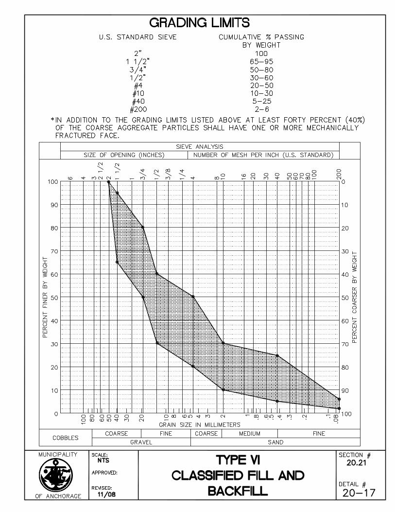
SECTION 20.21 CLASSIFIED FILL AND BACKFILL............................................... 58 Article 21.1 General ......................................................................................... 58 Article 21.2 Material ......................................................................................... 58 Article 21.3 Construction.................................................................................. 60 Article 21.4 Measurement ................................................................................ 61 Article 21.5 Basis of Payment .......................................................................... 62
SECTION 20.22 LEVELING COURSE .................................................................... 63 Article 22.1 General ......................................................................................... 63 Article 22.2 Material ......................................................................................... 63 Article 22.3 Construction.................................................................................. 64 Article 22.4 Measurement ................................................................................ 65 Article 22.5 Basis of Payment .......................................................................... 65
SECTION 20.23 COBBLES ..................................................................................... 66 Article 23.1 General ......................................................................................... 66 Article 23.2 Materials ....................................................................................... 66 Article 23.3 Construction.................................................................................. 66 Article 23.4 Measurement ................................................................................ 66 Article 23.5 Basis of Payment .......................................................................... 66
SECTION 20.24 RIPRAP......................................................................................... 67 Article 24.1 General ......................................................................................... 67 Article 24.2 Materials ....................................................................................... 67 Article 24.3 Construction.................................................................................. 67 Article 24.4 Method of Measurement ............................................................... 68 Article 24.5 Basis of Payment .......................................................................... 68

v
SECTION 20.25 GEOTEXTILE FABRIC ................................................................. 69 Article 25.1 Description .................................................................................... 69 Article 25.2 Materials ....................................................................................... 69 Article 25.3 Construction.................................................................................. 72 Article 25.4 Method of Measurement ............................................................... 74 Article 25.5 Basis of Payment .......................................................................... 74
SECTION 20.26 INSULATION................................................................................. 75 Article 26.1 General ......................................................................................... 75 Article 26.2 Materials ....................................................................................... 75 Article 26.3 Construction.................................................................................. 75 Article 26.4 Measurement ................................................................................ 76 Article 26.5 Basis of Payment .......................................................................... 76
SECTION 20.27 DISPOSAL OF UNUSABLE OR SURPLUS MATERIAL............... 77 Article 27.1 General ......................................................................................... 77 Article 27.2 Construction.................................................................................. 77 Article 27.3 Cesspools, Privy Pits and Septic Tanks........................................ 77 Article 27.4 Measurement ................................................................................ 77 Article 27.5 Basis of Payment .......................................................................... 78
SECTION 20.28 RECONSTRUCT DRIVEWAY....................................................... 79 Article 28.1 Description .................................................................................... 79 Article 28.2 Materials ....................................................................................... 79 Article 28.3 Construction.................................................................................. 79 Article 28.4 Measurement ................................................................................ 80 Article 28.5 Basis of Payment .......................................................................... 80
SECTION 20.29 PIPE CASING ............................................................................... 81 Article 29.1 General ......................................................................................... 81 Article 29.2 Materials ....................................................................................... 81 Article 29.3 Construction.................................................................................. 81 Article 29.4 Measurement ................................................................................ 81 Article 29.5 Basis of Payment .......................................................................... 81
SECTION 20.30 SHORING, SHEETING AND BRACING/SHORING AND SHEETING LEFT IN THE TRENCH AND PORTABLE................. 82
Article 30.1 General ......................................................................................... 82 Article 30.2 Materials ....................................................................................... 82 Article 30.3 Construction.................................................................................. 82 Article 30.4 Measurement ................................................................................ 82 Article 30.5 Basis of Payment .......................................................................... 82

Page 1 Standard Construction Specifications 2015 MASS Division 20 - Earthwork 1/15
STANDARD CONSTRUCTION SPECIFICATIONS FOR EARTHWORK DIVISION 20
SECTION 20.01 GENERAL
For the purposes of this Division, the terms “unsuitable” and “unusable” are equivalent when used as a description of a type of material and may be used interchangeably.
Article 1.1 Scope of Work
The Work covered by this Division consists of providing all plant, labor, equipment, supplies, material, transportation, handling, and storage, and performing all operations pertaining to the: 1) construction of subbase for parking lots, streets, alleys, curbs, gutters, sidewalks and bike trails, 2) construction for all trench excavation, backfill, bedding, and foundation material for utility installation; and 3) excavation and backfill for building structures and retaining walls.
Article 1.2 Definitions
A. Backfill
Material placed in an excavated area.
B. Bedding
Ground or support in which pipe is laid.
C. Borrow
Material used as fill and/or backfill which is obtained from a source other than required excavation.
D. Compaction
Tamping by hand or machine to achieve required density in soils.
E. Disposal Site
Any area where waste, unsuitable, unusable or surplus material from construction is placed. Contractor provided disposal sites are delineated in Division 10, Section 10.04, Article 4.9 – Disposal Sites.
F. Excavation
Area or material removed to provide a suitable base for improvement.
G. Fill
Fill is considered the material placed above the original or natural ground line.
H. Leveling Course
Leveling course is compacted material placed above the subbase and below the finishing surface of the improvement.
Page 2 Standard Construction Specifications 2015 MASS Division 20 - Earthwork 1/15
I. Non-Frost-Susceptible Material
Non-organic soil containing less than three percent (3%) by weight of grains smaller than .02 mm obtained from minus three inches (-3") material.
J. Service Connection
Any connection from a main line utility or storm drain to a property line for the purpose of providing service to an individual property
K. Subbase
The subbase is compacted material placed above the subgrade and below the leveling course.
L. Subgrade or Bottom Excavation
The subgrade is material below the bottom of excavation and upon which the subbase material is placed.
M. Trench
Any excavation for a utility or drainage system.
N. Unsuitable or Unusable Material
Unsuitable or unusable material may consist of any material which is, in the opinion of the Engineer, inadequate for use in the proposed construction.
Article 1.3 Applicable Standards
The latest revision of the following standards of the American Society for Testing and Materials (ASTM) and the American Association of State Highway Transportation Officials (AASHTO) are hereby made a part of these specifications:
ASTM C-29 Test for Unit Weight of Aggregate
ASTM C-117 Test for Materials Finer than No. 200 Sieve in Aggregates by Washing
ASTM C-131 Test for Resistance to Abrasion of Small Size Coarse Aggregate by Use of the Los Angeles Machine
ASTM C-136 Test for Sieve or Screen Analysis of Fine and Coarse Aggregates
ASTM D-422 Test for Particle Size Analysis of Soil
ASTM D-424 Test for Plastic Limit and Plasticity Index of Soils
AASHTO M-147 Materials for Aggregate and Soil-Aggregate Subbase, Base, and Surface Courses
AASHTO T-180-D Test for Moisture-Density Relations of Soils
AASHTO T-205 Test for Field Determination of Density of Soil In-Place
AASHTO T-238 Test for Density of Soil In-Place by Nuclear Method.
Article 1.4 Equipment
All equipment, tools, and machines used in the performance of the Work covered by these Specifications shall be subject to the approval of the Engineer and shall comply with all applicable safety requirements. All equipment used on the project shall be
Page 3 Standard Construction Specifications 2015 MASS Division 20 - Earthwork 1/15
adequately maintained and shall be the proper equipment for the Work being accomplished so as to produce the result required by the Contract Documents.
Article 1.5 Compaction Standards
The required density of fill and backfill shall meet the requirements as outlined in Section 20.21 - Classified Fill and Backfill. In areas outside of road rights-of-way, the density shall be as required by the Contract Documents or as directed by the Engineer.
Where compaction density is specified, the maximum density shall be determined in accordance with the current requirements of AASHTO Standard Method T-180-D.
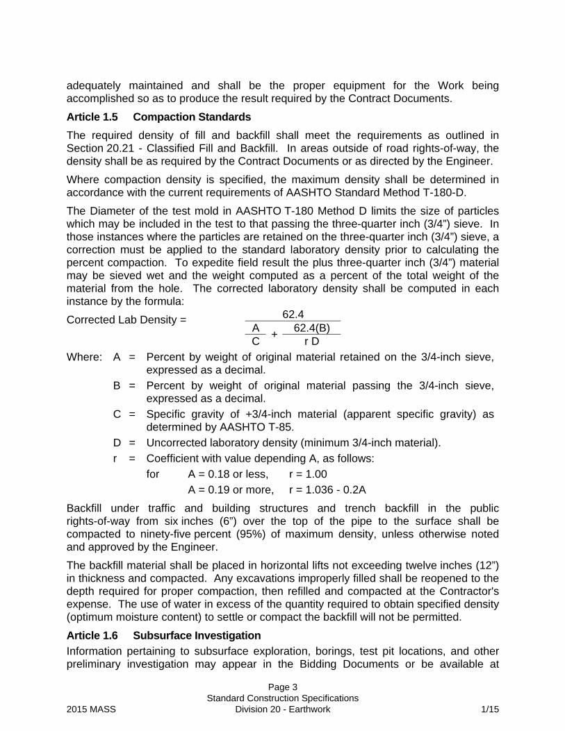
The Diameter of the test mold in AASHTO T-180 Method D limits the size of particles which may be included in the test to that passing the three-quarter inch (3/4”) sieve. In those instances where the particles are retained on the three-quarter inch (3/4”) sieve, a correction must be applied to the standard laboratory density prior to calculating the percent compaction. To expedite field result the plus three-quarter inch (3/4”) material may be sieved wet and the weight computed as a percent of the total weight of the material from the hole. The corrected laboratory density shall be computed in each instance by the formula:
62.4 A 62.4(B)
Corrected Lab Density =
C+
r D
A = Percent by weight of original material retained on the 3/4-inch sieve, expressed as a decimal.
B = Percent by weight of original material passing the 3/4-inch sieve, expressed as a decimal.
C = Specific gravity of +3/4-inch material (apparent specific gravity) as determined by AASHTO T-85.
D = Uncorrected laboratory density (minimum 3/4-inch material).
Coefficient with value depending A, as follows:
A = 0.18 or less, r = 1.00
Where:
r =
for
A = 0.19 or more, r = 1.036 - 0.2A
Backfill under traffic and building structures and trench backfill in the public rights-of-way from six inches (6”) over the top of the pipe to the surface shall be compacted to ninety-five percent (95%) of maximum density, unless otherwise noted and approved by the Engineer.
The backfill material shall be placed in horizontal lifts not exceeding twelve inches (12”) in thickness and compacted. Any excavations improperly filled shall be reopened to the depth required for proper compaction, then refilled and compacted at the Contractor's expense. The use of water in excess of the quantity required to obtain specified density (optimum moisture content) to settle or compact the backfill will not be permitted.
Article 1.6 Subsurface Investigation
Information pertaining to subsurface exploration, borings, test pit locations, and other preliminary investigation may appear in the Bidding Documents or be available at

Page 4 Standard Construction Specifications 2015 MASS Division 20 - Earthwork 1/15
selected locations for review by the Bidder. This information was acquired for design purposes only and is not considered adequate for construction.
The soils classifications and geotechnical designations recorded are informational only and represent only those subsurface conditions on the particular date, at the specific location, as indicated on each soils log and on the plans. The ground water levels indicated on the test hole logs and shown on the Drawings were recorded at the time the test holes were performed. These water levels may vary seasonally and are shown for design and informational purposes only. Contractor shall assume responsibility for any conclusions that may be drawn from such information and the conclusions shall not be considered just cause for a claim for additional compensation or contract time extension. Contractor should obtain and analyze such additional information as the Contractor may feel necessary and shall be responsible for any conclusions drawn from that information.
The Owner does not warrant the correctness of the soils investigation or of any interpretation, deduction, or conclusion given in the report relative to subsurface conditions. The Bidder shall make his own deductions and conclusions as to the nature of the materials to be excavated, the difficulties of making and maintaining the required excavations, the difficulties which may arise from subsurface conditions, and of doing any other Work affected by the subsurface conditions, and shall accept full responsibility therefore.
Article 1.7 Weather Limitations
Unless otherwise authorized by the Engineer, fill and backfill material, base course, and leveling course shall not be placed when the atmospheric temperature is below thirty-five degrees Fahrenheit (35F). When the temperature falls below thirty-five degrees Fahrenheit (35F), it shall be the responsibility of the Contractor to protect all areas of completed Work against any detrimental effects. Any areas of Work not completed in accordance with the Contract Documents that are damaged by weather shall be reconditioned, reshaped, and recompacted by the Contractor in conformance with the requirements of the Contract Document without additional cost to the Owner.
Article 1.8 Underground Utilities
The Contractor shall continuously support underground utilities during backfill placement and compaction. During backfill placement and compaction, the Contractor shall place geotextile fabric with a minimum twelve inch (12”) separation from underground utilities, unless directed otherwise by the Engineer.
Article 1.9 Contaminated Material
Unless otherwise noted in the Contract Documents, the Owner is not aware of any contaminated material within the project limits. If such material is encountered, Contractor shall notify the Engineer immediately for direction. Unless the contamination was caused by Contractor’s operation, discovery of contaminated material will be treated as a changed condition per Division 10, Section 10.05, Article 5.18 – Changed Conditions.

Page 5 Standard Construction Specifications 2015 MASS Division 20 - Earthwork 1/15
SECTION 20.02 STORM WATER POLLUTION PREVENTION PLAN
Article 2.1 General
The Work described in this Section shall consist of providing all labor, equipment, materials, and services to prepare, implement, and maintain a Storm Water Pollution Prevention Plan (SWPPP) for projects that may adversely impact receiving waters or waters of the United States. The type of plan required depends on the area disturbed by the project including the construction site and off-site activities which include, but may not be limited to, material sites, waste disposal sites, borrow and fill sites, and equipment and material storage areas.
For Projects that impact an area greater than five hundred (500) square feet or are deeper than four feet (4’), and less than ten thousand (10,000) square feet, a Type 1 SWPPP is required and the cost of the SWPPP is considered incidental to the Contract and no separate payment shall be made. A Type 2 SWPPP is required for Projects that disturb a project area greater than ten thousand (10,000) square feet and less than one (1) acre. A Type 3 SWPPP is required for all Projects that disturb one or more acres of land.
As a requirement of this Contract, the Contractor shall accept a delegation of authority from the Municipality to act as the Municipality's duly authorized representative for the purpose of overseeing compliance with the APDES Construction Permit at the project site.
Article 2.2 Definitions
Alaska Certified Erosion and Sediment Control Lead (AK-CESCL) - A person who has completed training, testing, and other requirements of, and is currently certified as, an AK-CESCL from an AK-CESCL Training Program (a program developed under a Memorandum of Understanding between the Municipality and others). The Municipality recognizes AK-CESCLs as “qualified personnel” required by the CGP. An AK-CESCL shall be recertified every three years.
Alaska Department of Environmental Conservation (ADEC) - The State agency authorized by EPA to administer the Clean Water Act’s National Pollutant Discharge Elimination System (NPDES).
Alaska Pollutant Discharge Elimination System (APDES) - A system administered by ADEC that issues and tracks permits for storm water discharges.
Best Management Practices (BMPs) - Temporary or permanent structural and non-structural devices, schedules of activities, prohibition of practices, maintenance procedures, and other management practices to prevent or minimize the discharge of pollutants to waters of the United States. BMPs also include, but are not limited to, treatment requirements; operating procedures; practices to control site runoff, spillage or leaks; sludge or waste disposal; or drainage from material storage.
Clean Water Act (CWA) - Federal Water Pollution Control Amendments of 1972, as amended (33 U.S.C. 1251 et seq.).

Page 6 Standard Construction Specifications 2015 MASS Division 20 - Earthwork 1/15
Construction Activity - Work by Contractor, subcontractor or utility company within the project area, that may result in erosion, sedimentation, or a discharge of pollutants into storm water. Construction Activity includes soil disturbing activities (e.g. clearing, grubbing, grading, excavating); construction materials or equipment storage or maintenance areas (e.g. material piles, borrow area, concrete truck chute wash down, fueling); and activities that may discharge storm water and are directly related to the construction process (e.g. concrete or asphalt batch plants).
Construction General Permit (CGP) - The current permit authorizing storm water discharges from Construction Activities, issued and enforced by ADEC. The CGP authorizes storm water discharges provided permit conditions and water quality standards are met.
Electronic Notice of Intent (eNOI) - The electronic Notice of Intent submitted to ADEC to obtain coverage under the CGP.
Electronic Notice of Termination (eNOT) - The electronic Notice of Termination submitted to ADEC to end coverage under the CGP.
Environmental Protection Agency (EPA) - A federal agency charged to protect human health and the environment.
Final Stabilization – The CGP defines Final Stabilization as:
1. All soil disturbing activities at the site have been completed and either of the two following criteria have been met:
a. A uniform (e.g.,evenly distributed, without large bare areas) perennial vegetative cover for the area has been established on all unpaved areas and areas not covered by permanent structures, or
b. Equivalent non-vegetative permanent stabilization measures have been employed (such as use of rip rap, gabions, porous backfill (ADOT&PF specification 703-2.10), railroad ballast or subballast, ditch lining (ADOT&PF Specification 610-2.01 with <3% smaller than #200 sieve), geotextiles, or fill material with low erodibility as determined by an engineer familiar with the site and documented in the SWPPP.
2. When background native vegetation will cover less than one hundred percent (100%) of the ground (e.g., arid areas, beaches), the seventy percent (70%) coverage is adjusted as follows: if the native vegetation covers fifty percent (50%) (0.70 X 0.50 = 0.35), thirty-five percent (35%) total cover is required for final stabilization. On a beach with no natural vegetation, no stabilization is required.
3. In arid and semi arid areas only, all soil disturbing activities at the site have been completed and both of the following criteria have been met:
a. Temporary erosion control measures (e.g., degradable rolled erosion control product) are selected, designed, and installed along with an appropriate seed base to provide erosion control for at least three years without active maintenance by the permitee:

Page 7 Standard Construction Specifications 2015 MASS Division 20 - Earthwork 1/15
b. Temporary erosion control measures are selected, designed, and installed to achieve seventy percent (70%) vegetative coverage within three years.
4. For individual lots in residential construction, final stabilization occurs when either:
a. The homebuilder has completed final stabilization as specified above, or
b. The home builder has temporary stabilization including perimeter controls for an individual lot prior to occupation of the home by the homeowner and informing the homeowner of the need for, and benefits of, final stabilization.
Hazardous Material Control Plan (HMCP) - The Contractor's detailed project specific plan for prevention of pollution from storage, use, transfer, containment, cleanup, and disposal of hazardous material (including, but not limited to, petroleum products related to construction activities and equipment). The Contractor shall include the HMCP as an appendix to the SWPPP.
Inspection - An inspection required by the CGP or the SWPPP, usually performed together by the Contractor’s SWPPP Manager and the Municipal Inspector.
Municipal Separate Storm Sewer System (MS4) Permit - An ADEC storm water discharge permit issued to local governments (Municipality) and other public bodies, for operation of storm water conveyances and drainage systems. See CGP for further definition
Multi-Sector General Permit (MSGP) - The Alaska Pollutant Discharge Elimination System General Permit for storm water discharges associated with industrial activity.
Operator(s) - The party or co-parties associated with a regulated activity that has responsibility to obtain permit coverage under the CGP. ”Operator” for the purpose of the CGP and in the context of storm water associated with construction activity, means any party associated with a construction project that meets either of the following two criteria:
1. The operator has operational control over construction plans and specifications, including the ability to make modifications to those plans and specifications; or
2. The operator has day to day responsibility and operational control for all activities at a project which are necessary to fully comply with the CGP and the project SWPPP for the site or other requirements of the permit. For the purpose of a Contractor executing project Work under this Contract with the Municipality, the Contractor is the operator responsible for CGP and SWPPP coverage and compliance under the CGP for the Work.
Permit - References to permit pursuant to Division 20, Section 20.02 shall mean the Construction General Permit (CGP) defined above.
Pollutant - Any substance or item meeting the definition of pollutant contained in 40 CFR § 122.2. A partial listing from this definition includes: dredged spoil, solid

Page 8 Standard Construction Specifications 2015 MASS Division 20 - Earthwork 1/15
waste, sewage, garbage, sewage sludge, chemical wastes, biological materials, wrecked or discarded equipment, rock, sand, cellar dirt, and industrial or municipal waste.
Project Zone - The Project Zone includes the area of street, road, highway or other facility under construction; project staging and equipment areas; and material and disposal sites, when those areas, routes and sites are directly related to the Contract.
Records - Any record, report, information, document, or photograph required to be created or maintained pursuant to the requirements of the CGP, the CGP storm water requirements of the Clean Water Act and applicable local, state, and federal laws and regulations pertaining to document preservation.
Spill Prevention, Control and Countermeasure Plan (SPCC Plan) - Contractor’s detailed plan for petroleum spill prevention and control measures that conform to the requirements of 40 CFR 112.
Spill Response Field Representative - Contractor’s representative with authority and responsibility for managing, implementing, and executing the HMCP and SPCC Plan.
Storm Event - A rainfall event that produces more than one half inch (0.5”) of precipitation in twenty-four (24) hours and that is separated from the previous storm event by at least three (3) days of dry weather. Event can be measured on site using a rain gauge or Contractor can utilize the nearest National Weather Service (NWS) precipitation gauge station to determine the amount of rain fall during a storm event if the NWS gauge used is located within twenty (20) miles of the site.
Storm Water Pollution Prevention Plan (SWPPP) - Contractor’s detailed project- specific plan to minimize erosion and contain sediment within the Project Zone and to prevent discharge of pollutants that exceed applicable water quality standards. The SWPPP includes, but is not limited to the plan, amendments, records of activities, inspection schedules and reports, qualifications of key personnel, and all other documentation, required by the CGP and this specification, and other applicable local, state, and federal laws and regulations.
Storm Water Pollution Prevention Plan Type
Type 1- if area of disturbance is 500 to <10,000 square feet or 4 feet or more in depth and is not part of a common plan of development that disturbs 10,000 square feet or more.
Type 2- if the area of ground disturbance is 10,000 square feet or greater but less than 1 acre and not part of a common plan of development that disturbs one acre or more.
Type 3 - if the area of disturbance is 1 acre or greater, or part of a common development that disturbs one or more acres.

Page 9 Standard Construction Specifications 2015 MASS Division 20 - Earthwork 1/15
Subcontractor Spill Response Coordinator - The Subcontractor’s Representative with authority and responsibility for coordinating the Subcontractor’s activities in compliance with the HMCP and SPCC Plan.
Subcontractor SWPPP Coordinator - The Subcontractor’s Representative has responsible charge of and authority to direct the Subcontractor’s Work; is responsible for the subcontractor’s compliance with the SWPPP; and performs coordination with the Superintendent and SWPPP Manager.
Superintendent - Contractor’s duly authorized representative in responsible charge of the Work. The Superintendent has responsibility and authority for the overall operation of the Project and for Contractor-furnished sites and facilities directly related to the Project.
SWPPP Amendment - A revision or document that adds to, deletes from, or modifies the SWPPP.
SWPPP Manager - Contractor’s qualified representative who conducts inspections, has authority to suspend work and implement corrective actions required for CPG compliance, except they do not have authority to prepare the initial SWPPP or sign inspection reports.
SWPPP Preparer - Contractor’s qualified representative who is responsible for developing the initial SWPPP.
Utility Spill Response Coordinator - a utility’s representative with authority and responsibility for coordinating the Utility’s activities in compliance with the HMCP and SPCC Plan.
Utility SWPPP Coordinator - a utility’s representative with authority to direct the Utility’s work, and who is responsible for coordination with the Superintendent and SWPPP Manager, and for the utility’s compliance with the SWPPP.
Article 2.3 Applicable Standards
The latest version of the following permits, standard and requirements are hereby made a part of these specifications:
A. Alaska 2011 Construction General Permit (CGP) #100000
B. Alaska Department Of Environmental Conservation (ADEC) Storm Water Pollution Prevention Plan (SWPPP) Template
C. Municipal Separate Storm Sewer System (MS4) Permit
Article 2.4 Plan and Permit Submittals
Partial and incomplete submittals will not be accepted for review. A submittal that is re-submitted or revised after submission, but before the review is completed, will restart the submittal review timeline. No additional Contract time or additional compensation will be allowed due to delays caused by partial or incomplete submittals, or required re-submittals.
Page 10 Standard Construction Specifications 2015 MASS Division 20 - Earthwork 1/15
A. Storm Water Pollution Prevention Plan (SWPPP)
Contractor shall submit an electronic copy and three hard copies of the SWPPP to the Engineer for approval. Contractor shall organize and bind the SWPPP and related documents for submittal according to the requirements of Article 2.9
The Municipality will review the SWPPP submittals within ten (10) business days after they are received. Submittals will be returned to the Engineer, and marked as either “rejected” with reasons listed or as “approved” by the Municipality. When the submittal is rejected, the Contractor shall revise and resubmit the SWPPP. The ten (10) business days review period will restart when the Contractor resubmits an electronic copy and three hard copies of the revised SWPPP to the Engineer for approval.
After the SWPPP is approved by the Municipality, the Contractor shall sign and certify the approved SWPPP.
B. Hazardous Material Control Plan (HMCP)
Contractor shall submit an electronic copy and three hard copies of the HMCP, as an appendix to the SWPPP, to the Engineer for approval. The HMCP submittal and review timeline, and signature requirements are the same as the SWPPP. The HMCP shall be appended to and submitted with the SWPPP.
C. Spill Prevention, Control and Countermeasure Plan (SPCC)
When a SPCC Plan is required under Article 2.11, Contractor shall submit an electronic copy and three signed hard copies of the SPCC Plan to the Engineer. at least 21 days before beginning Construction Activity. The Municipality reserves the right to review the SPCC Plan and require modifications.
D. Construction General Permit (CGP) Coverage
The Contractor is responsible for permitting of Contractor and subcontractor Construction Activities related to the Project, including any material sites, waste disposal sites, borrow & fill sites, and equipment and material storage areas that are not covered by a different permit.
Prior to beginning Construction Activity, Contractor shall submit an eNOI with the required fee to ADEC for coverage under the Construction General Permit (CGP). Submit a copy of the signed eNOI and ADEC’s acknowledgement letter to the Engineer as soon as practicable and no later than three days after filing eNOI or receiving a written responses from ADEC.
The Contractor shall not begin Construction Activity until in full compliance with the conditions listed in Article 2.14.A.
The Municipality will submit an eNOI to ADEC for Construction Activities on Municipal Projects if required. The Engineer will provide the Contractor with a copy of the Municipality’s eNOI and ADEC’s written acknowledgment by letter, or other document for inclusion in the SWPPP.

Page 11 Standard Construction Specifications 2015 MASS Division 20 - Earthwork 1/15
E. Ending CGP Coverage
Contractor shall submit an eNOT to ADEC, and submit both a copy of the signed eNOT and ADEC’s acknowledgement letter to the Municipality, within 30 days after the Engineer has determined the Contractor has fully complied with the conditions listed in Article 2.16.F.
F. Local MS4 SWPPP Review
When installing Permanent Storm Water Management Controls in accordance with CGP Part 4.9, the Contractor shall submit information required by the Municipality for the project and shall obtain approval prior to commencement of construction activities.
1. transmit a copy of information as required to local MS4 (Municipality); with the required fee using delivery receipt confirmation;
2. transmit a copy of the delivery receipt confirmation to the Engineer within seven (7) days of receiving the confirmation;
3. transmit a copy of any comments by the local MS4 (Municipality) to the Engineer within seven (7) days of receipt;
4. amend the SWPPP as necessary to address local MS4 (Municipality) comments and transmit SWPPP Amendments to the Engineer within seven (7) days of receipt of the comments; and
5. include a copy of the Municipality approval letter in the SWPPP.
G. Modifying Contractor’s eNOI
When required by The CGP Part 2.7, Contractor shall modify the eNOI to update or correct information. Reasons for modification include a change in start or end dates, small changes in number of acres to be disturbed, change in decision to use or not use treatment chemicals, or change in location of SWPPP Records.
The Contractor shall submit an eNOT and then submit a new eNOI instead of an eNOI modification when: the operator has changed, the original eNOI indicates disturbed area less than five acres and the project will disturb more than five acres, or a project over five disturbed acres grows by more than 50%.
Article 2.5 Personnel Qualifications.
A. General
Contractor shall provide documentation in the SWPPP that the individuals serving in these positions are “qualified Personnel” pursuant to the CGP.
The Municipality accepts persons having either of the following certificates as equivalent to AK-CESCL, if the certificates are current according to the sponsoring organization’s policies:
• CPESC - Certified Professional in Erosion and Sediment Control, or
• CISEC - Certified Inspector in Sediment and Erosion Control

Page 12 Standard Construction Specifications 2015 MASS Division 20 - Earthwork 1/15
B. SWPPP Preparer
The SWPPP Preparer shall meet at least one of the following qualifications:
• current certification as a Certified Professional in Erosion and Sediment Control (CPESC); or
• current certification as AK-CESCL, and at least three years experience in erosion and sediment control (provide documentation including project names, project timelines, and work responsibilities demonstrating the experience requirement); or
• Professional Engineer licensed in the State of Alaska
For Projects disturbing more than 20 acres, the SWPPP Preparer shall also have completed a SWPPP Preparation course.
C. Superintendent
The Superintendent shall hold current certification as AK-CESCL and be a duly authorized representative as defined in the CGP, Appendix A, Part 1.12.3 and Section 20.02 definitions.
D. SWPPP Manager
The SWPPP Manager shall have current certification as AK-CESCL, and shall meet the CGP experience, training, and authority requirements identified for the Storm Water Lead and Storm Water Inspector positions as defined in the CGP, Appendix C, Qualified Person.
E. Storm Water Inspector & Monitoring Person
The Storm Water Inspector and the Storm Water Monitoring Person shall have current certification as AK-CESCL.
F. Active Treatment System Operator
The Active Treatment System (ATS) operator shall have current certification as AK-CESCL and shall be knowledgeable in the principals and practices of treatment systems in general, including the operation of the project-specific ATS. Active Treatment System operator shall have at least six (6) months field experience with ATS, or completion of an ATS manufacturer’s training course, or completion of system operator’s certification course.
Article 2.6 Signature/Certfication Requirements and Delegations
A. eNOI and eNOT
The eNOI and eNOT shall be signed and certified by a responsible Contractor corporate officer according to CGP Appendix A, Part 1.12.2. Signature and certification authority for the eNOI and eNOT shall not be delegated.
B. Delegation of Signature Authority for Other SWPPP Documents and Reports
The Contractor shall use Form F-108 to delegate signature authority and certification authority to the Superintendent position, according to CGP Appendix A, Part 1.12.3, for the SWPPP, Inspection Reports and other reports required by
Page 13 Standard Construction Specifications 2015 MASS Division 20 - Earthwork 1/15
the CGP. The Superintendent position is responsible for signing and certifying the SWPPP, Inspection Reports, and other reports required by the CGP, except the eNOI and eNOT.
Engineer will provide the Municipality’s Form F-107, which delegates authority from the Municipality to act as the Municipality's duly authorized representative for the purpose of overseeing compliance with the APDES Construction Permit at the project site. The Contractor shall include Form F-107 in the SWPPP.
C. Subcontractor Certification
Subcontractors shall certify that they have read and will abide by the CGP and the conditions of the project SWPPP.
D. Signatures and Initials
Contractor and subcontractor personnel shall handwrite (wet ink) signatures or initials on CGP documents and SWPPP forms, wherever a signature or initial is required.
Article 2.7 Responsibility for Storm Water Permit Coverage
A. Contractor is responsible for permitting and permit compliance.
B. The Contractor has sole responsibility for compliance with ADEC and other applicable federal, state, and local requirements, and for securing all necessary clearances, rights, and permits.
C. An entity that owns or operates a commercial plant, material source, or disposal site receiving materials, waste, or any product generated as a result of the Project is responsible for permitting and permit compliance. The Contractor has sole responsibility to verify that the entity has appropriate permit coverage and to provide a copy of the permit documents to the Engineer.
D. Contractor shall indemnify, defend and hold the Municipality harmless for any and all fines resulting from non-compliance with the permit conditions.
Article 2.8 Utility Responsibilities
If a utility is working ahead of the main project, the utility shall follow the procedures in this Section, obtain SWPPP approval, and file an eNOI with ADEC prior to starting any ground disturbing activity.
Article 2.9 Storm Water Pollution Prevention Plan (SWPPP) Requirements
A. General
Contractor shall prepare SWPPP in accordance with the applicable standards of this Section. Contractor shall submit and maintain the SWPPP in three-ring binder with tabbed and labeled dividers for each section and appendix.
B. SWPPP Preparer and Pre-Construction Site Visit
Contractor shall hire or designate a SWPPP Preparer to prepare the SWPPP and associated documents according to the requirements of the CGP. The SWPPP

Page 14 Standard Construction Specifications 2015 MASS Division 20 - Earthwork 1/15
shall identify the SWPPP Preparer and include qualifications (including the expiration date of any certifications), title, and company name in the SWPPP.
The Contractor and SWPPP Preparer shall conduct a pre-construction inspection at the project site before construction activity begins. If the SWPPP Preparer is not a Contractor employee, the SWPPP Preparer shall visit the site accompanied by Contractor’s superintendent. Contractor shall provide the Municipality at least seven (7) days written notice of the site visit, so that the Municipality may participate.
During the pre-construction inspection, the SWPPP Preparer shall identify or, if a draft of the SWPPP has already been prepared, verify that the SWPPP fully addresses and describes:
1. opportunities to phase construction activities;
2. appropriate BMPs and their sequencing; and
3. sediment controls that shall be installed prior to beginning construction activities.
Contractor shall document the SWPPP Preparer’s pre-construction inspection in the SWPPP on Form F-106, SWPPP Pre-Construction Site Visit, including the names of attendees and the date.
C. SWPPP Development
Contractor shall prepare the SWPPP with sections and appendices, in accordance with the current ADEC SWPPP template and the following additional information:
1. Add additional appendices for:
a. Appendix L -- Hazardous Material Control Plan (HMCP)
b. Appendix M -- SWPPP Preparer’s Site Visit
c. Appendix N -- Rainfall Logs
d. Appendix O – NOT forms and Acknowledgement letters from ADEC (Include both Municipality’s and Contractor’s)
2. Obtain the following completed forms from the Municipality and include them in the SWPPP:
a. SWPPP Delegation of Signature Authority – (F-107)
b. SWPPP Certification for Municipality (F-109)
3. Use the following Municipality forms for recording information in the SWPPP:
a. SWPPP Amendment Log (F-114)
b. SWPPP Certification for Contractor (F-111)
c. SWPPP Construction Site Inspection Report (F-100 parts 1&2)
d. SWPPP Corrective Action Log (F-112)
e. SWPPP Daily Record of Rainfall (F-115)
f. SWPPP Delegation of Signature Authority Contractor (F-108)
g. SWPPP Grading and Stabilization Activities Log (F-110)

Page 15 Standard Construction Specifications 2015 MASS Division 20 - Earthwork 1/15
h. SWPPP Pre-Construction Site Visit (F-106)
i. SWPPP Subcontractor Certification (F-105)
j. SWPPP Training Log (F-125)
The forms are available on the municipal website, www.muni.org, under Project Management and Engineering Publications.
D. SWPPP Considerations and Contents
The SWPPP shall provide erosion and sediment control measures for all Construction Activity.
The SWPPP shall include the activities of the Contractor, all subcontractors, and utility companies performing Work. The SWPPP shall describe the roles and responsibilities of the Contractor, subcontractors, and utility companies with regard to implementation of the SWPPP.
The SWPPP shall identify all operators for the Project including utility companies performing Construction Activity, and identify the areas over which each operator has operational control and where the Municipality and Contractor are co-operators.
The SWPPP shall include any material sites, waste disposal sites, borrow and fill sites, and equipment and material storage sites. If those sites are covered under a different permit or operated by a different entity, the Contractor shall provide the permit information and/or operational information as part of the SWPPP.
Contractor shall prepare the SWPPP according to the requirements of the CGP and this specification, including accounting for the Contractor’s construction methods and phasing, and identifying the amount of mean annual precipitation.
Contractor shall include an Antidegredation Analysis in the SWPPP, if storm water from the Project discharges into a receiving water that is considered a high quality water and constitutes an outstanding national resource. The Municipality does not provide the analysis. The Contractor shall perform this analysis according to the CGP Part 2.1.5.
There are special requirements in the CGP Part 3.2, for storm water discharges into an impaired water body, which may include monitoring of storm water discharges. For projects meeting the permit criteria, the Contractor is responsible for compliance with the CGP Part 3.2 inside and outside the Project Zone.
Contractor shall preserve natural topsoil where possible. Contractor shall delineate the site in accordance to CGP Part 4.1. Contractor shall use stakes, flags, or silt fence, etc. to identify areas where land disturbing activities will occur and areas that will be left undisturbed. Contractor shall minimize the amount of soil exposed during Construction Activity in accordance to CGP Part 4.1.2.
Contractor shall conform to the dewatering requirements of CGP Part 4.3.

Page 16 Standard Construction Specifications 2015 MASS Division 20 - Earthwork 1/15
The SWPPP shall identify specific areas where potential erosion, sedimentation, or pollution may occur. The potential for wind erosion shall be addressed. The potential for erosion at drainage structures shall be addressed.
SWPPP shall include in the “Stabilize Soils” section, a description of how the Contractor will minimize the amount of disturbed and unstabilized ground in the fall season. Contractor shall identify anticipated dates of fall freeze-up and spring thaw. Contractor’s SWPPP shall describe how the Contractor will stabilize areas when it is close to or past the seasonal time of snow cover or frozen conditions, and before the first seasonal thaw. Contractor’s SWPPP shall include a plan for final stabilization. Plans for Active Treatment Systems shall be submitted to ADEC for review at least fourteen (14) days prior to their application and the Operator of the ATS identified in the SWPPP. Treatment chemicals shall be identified on the NOI.
The SWPPP shall provide designated areas for equipment and wheel washing, equipment fueling and maintenance, chemical storage, staging or material storage, waste or disposal sites, concrete washouts, paint and stucco washouts, and sanitary toilets. These activities shall be done in designated areas that are located, to the extent practicable, away from drain inlets, conveyance channels, and waters of the US. No discharges are allowed from concrete washout, paint and stucco washout; or from release oils, curing compounds, fuels, oils, soaps, and solvents. Equipment and wheel washing water may be treated and discharged.
Contractor shall implement temporary BMPs for a two (2)-year-twenty-four (24) hour storm event. Contractor shall describe BMPs in the SWPPP and in SWPPP Amendments, including source controls, sediment controls, discharge points, and all temporary and permanent stabilization measures. Contractor’s SWPPP shall describe the design, placement, installation, and maintenance of each BMP, using words and drawings as appropriate. Contractor shall provide a citation to the BMP Manual or publication used as a source for the BMP, including the title of the BMP Manual or publication, the author (individual or agency), and date of publication. If no published source was used to select or design a BMP, then the SWPPP or SWPPP amendment shall state that “No BMP manual or publication was used for this design.”
Contractor shall describe the sequence and timing of activities that disturb soils and of BMP implementation and removal. Contractor shall phase earth disturbing activities to minimize unstabilized areas and to achieve temporary or final stabilization quickly. Whenever practicable, the Contractor shall incorporate final stabilization work into excavation, embankment and grading activities.
Contractor shall identify the inspection frequency in the SWPPP. At a minimum the inspection frequency shall be:
• at least once every seven (7) days during construction; or
• at least once every fourteen (14) days during construction and within twenty-four (24) hours of the end of a storm event of one-half inch (1/2”)

Page 17 Standard Construction Specifications 2015 MASS Division 20 - Earthwork 1/15
or greater rainfall in a twenty-four (24) hour period (one-half inch (1/2”) rainfall as recorded at the project site rain gauge)
The SWPPP shall cite and incorporate applicable requirements of the Project permits, environmental commitments, and commitments related to historic preservation. Make additional consultations or obtain permits as necessary for Contractor specific activities which were not included in the Municipality’s permitting and consultation.
The SWPPP is a dynamic document. The Contractor shall maintain the SWPPP current by noting installation, modification, and removal of BMPs, and by using amendments, SWPPP amendment logs, Inspection Reports, corrective action logs, records of land disturbance and stabilization, and other records necessary to document storm water pollution prevention activities and to satisfy the requirements of the CGP and this specification.
E. Recording Personnel and Contact Information in the SWPPP.
Contractor shall include records of the AK-CESCL cards or certificates for the Superintendent, SWPPP Manager, acting Superintendent and acting SWPPP Managers in the SWPPP.
Contractor shall provide twenty-four- (24)-hour contact information for the Superintendent and SWPPP Manager. The Superintendent and SWPPP Manager shall have twenty-four- (24)-hour contact information for all Subcontractor SWPPP Coordinators and Utility SWPPP Coordinators.
Article 2.10 Hazardous Material Control Plan (HMCP) Requirements
Contractor shall prepare the HMCP for prevention of pollution from storage, use, containment, cleanup, and disposal of hazardous material, including petroleum products related to construction activities and equipment. Contractor shall append the HMCP to the SWPPP. Contractor shall compile Material Safety Data Sheets (MSDS) in one location and reference that location in the HMCP.
HMCP shall designate a Contractor’s Spill Response Field Representative and provide twenty-four- (24)-hour contact information. Contractor shall designate a Subcontractor Spill Response Coordinator for each Subcontractor. The Superintendent and Contractor’s Spill Response Field Representative shall have twenty-four- (24)-hour contact information for each Subcontractor Spill Response Coordinator and the Utility Spill Response Coordinator.
HMCP shall list and provide the location and estimated quantities of hazardous materials (including materials or substances listed in 40 CFR 117 and 302, and petroleum products) to be used or stored on the Project. Hazardous materials shall be stored in covered storage areas. Contractor shall provide secondary containment for all hazardous material storage areas.
HMCP shall identify the locations where fueling and maintenance activities will take place and describe the activities, and list controls to prevent the accidental spillage of petroleum products and other hazardous materials. Controls include placing absorbent
Page 18 Standard Construction Specifications 2015 MASS Division 20 - Earthwork 1/15
pads or other suitable containment under fill ports while fueling and under equipment during maintenance or repairs.
HMCP shall use secondary containment under all stationary equipment (equipment that does not have a seat for driving) that contains petroleum products and use secondary containment under pumps, compressors, and generators.
HMCP shall list the types and approximate quantities of response equipment and cleanup materials available on the Project, including a list and location map of cleanup materials at each different work site and readily available off site (materials sources, material processing sites, disposal sites, staging areas, etc). Spill response materials shall be stored in sufficient quantity at each work location, appropriate to the hazards associated with that site.
HMCP shall describe procedures for containment and cleanup of hazardous materials. Contractor shall describe a plan for the prevention, containment, cleanup, and disposal of soil and water contaminated by spills and a plan for dealing with contaminated soil and water encountered during construction. Contractor shall clean up spills or contaminated surfaces immediately.
HMCP shall describe methods of disposing of waste petroleum products and other hazardous materials generated by the Project, including routine maintenance. Contractor shall identify haul methods and final disposal areas and provide assurance that final disposal areas are permitted for hazardous material disposal.
HMCP shall describe methods of complying with the requirements of AS 46.04.010-900, Oil and Hazardous Substances Pollution Control, and 18 AAC 75, including contact information for reporting hazardous materials and petroleum product spills to the Project Engineer and reporting to federal, state and local agencies.
Article 2.11 Spill Prevention, Control, and Countermeasure Plan (SPCC Plan) Requirements
Contractor shall prepare and implement an SPCC Plan when required by 40 CFR 112 and when both of the following conditions are present on the Project:
• oil or petroleum products from a spill may reach navigable waters (as defined in 40 CFR 112); and
• total above ground storage capacity for oil and petroleum products is greater than 1,320 gallons (not including onboard tanks for fuel or hydraulic fluid used primarily to power the movement of a motor vehicle or ancillary onboard oil-filled operational equipment, and not including containers with a storage capacity of less than 55 gallons)
HMCP and SWPPP shall reference the SPCC plan.
Article 2.12 Superintendent and SWPPP Manager Responsibility and Authority
Contractor’s superintendent is responsible for the overall operation of the Project and all Contractor-furnished sites and facilities directly related to the Project. The Superintendent shall sign and certify the SWPPP, Inspection Reports, and other reports required by the CGP except the NOI and NOT. The Superintendent may not delegate

Page 19 Standard Construction Specifications 2015 MASS Division 20 - Earthwork 1/15
the task or responsibility of signing and certifying the SWPPP submitted under Article 2.4, Inspection Reports, and other reports required by the CGP.
The Superintendent may assign certain duties to the SWPPP Manager, which may include:
• ensuring Contractor’s and subcontractor’s compliance with the SWPPP and CGP;
• ensuring the control of erosion, sedimentation, or discharge of pollutants;
• directing and overseeing installation, maintenance, and removal of BMPs;
• performing Inspections; and
• updating the SWPPP including adding amendments and forms.
Contractor shall ensure that Superintendent and SWPPP Manager are knowledgeable in the requirements of this Section, the SWPPP, CGP, BMPs, HMCP, SPCC Plan, environmental permits, environmental commitments, and historic preservation commitments.
Contractor’s Superintendent and SWPPP Manager shall have the complete authority and shall be responsible for suspending construction activities that do not conform to the SWPPP or CGP.
Article 2.13 Materials
Contractor shall
• use materials suitable to withstand hydraulic, wind, and soil forces, and to control erosion and trap sediments according to the requirements of the CGP and the Specifications.
• use the temporary seed mixture specified by special provision, or use annual rye grass if no temporary seed mix is specified.
• use straw that is certified free of noxious weed by the United States Department of Agriculture(USDA), Natural Resources Conservation Service, Local Soil and Water Conservative District(NRCS). Alaska Weed Free Forage Certification Program shall be used when available. Hay may not be substituted for straw.
BMP’s shall conform to the latest version of Municipality of Anchorage Storm Water Manual or as approved by the Engineer
Article 2.14 Construction Requirements
Contractor shall be familiar with the requirements of the CGP. Contractor shall fully comply with the SWPPP and the requirements of the CGP.
A. Prior to Construction
Contractor shall complete the following actions before construction activity begins:
1. the SWPPP Preparer shall visit the Project, the visit shall be documented in the SWPPP, and the SWPPP shall be developed (or amended) with findings from the visit ;

Page 20 Standard Construction Specifications 2015 MASS Division 20 - Earthwork 1/15
2. the SWPPP shall be approved by the Engineer;
3. the Contractor shall be authorized to begin construction only by the Engineer;
4. the Project eNOIs for the Municipality and for the Contractor, as well as other eNOIs if there are additional operators, shall be listed as Active Status on the ADEC website before construction activity commences ;
5. Contractor shall post notices on project site containing the following information:
• Copy of all eNOIs related to this project
• Name and twenty-four- (24)-hour phone number of SWPPP Manager and Superintendent
• Location of the SWPPP
6. Contractor shall prominently post notices on the outside wall of the Contractor’s Project office and near the main entrances of the construction project. Postings shall be protected from the weather. Contractor shall locate postings so the public can read them without obstructing construction activities or the traveling public (for example, at an existing pullout). Do not use retro-reflective signs for the SWPPP posting. Do not locate SWPPP signs in locations where the signs may be confused with traffic control signs or devices. Contractor shall update the notices if the listed information changes.
7. Contractor shall install an outdoor rain gauge in accordance with manufacturer’s guidance in a readily accessible location on the Project.
8. Contractor shall delineate the site for both ground disturbing activities and areas that will be left undisturbed and install sediment controls and other BMPs that shall be placed prior to the initiation of Construction Activity.
B. During Construction
1. Contractor shall ensure subcontractors understand and comply with the SWPPP and the CGP, and have signed a SWPPP Subcontractor Certification, Form F-105. Contractor shall include SWPPP Subcontractor Certifications as an appendix to the SWPPP. Contractor shall provide SWPPP information to utility companies and coordinate with Subcontractors and utility companies doing work in the Project Zone so that BMPs, including but not limited to, temporary and permanent stabilization, are installed, maintained, and protected from damage.
2. Contractor shall provide on-going training to employees and Subcontractors, on control measures at the site and applicable storm water pollution prevention procedures. Training shall be documented on the SWPPP Training Log Form F-125, including the dates and attendees to these trainings. Contractor shall include the SWPPP Training Log as an appendix to the SWPPP.
3. Contractor shall notify the Engineer immediately if the actions of any utility company or Subcontractor do not comply with the SWPPP and the CGP.
4. Contractor shall not install concrete washout containment within one hundred (100) feet of wetlands and/or other water bodies.
Page 21 Standard Construction Specifications 2015 MASS Division 20 - Earthwork 1/15
5. Contractor shall comply with requirements of the HMCP and SPCC Plan, and all local, state and federal regulations that pertain to the handling, storage, containment, cleanup, and disposal of petroleum products or other hazardous materials.
6. Contractor shall keep the SWPPP current (refer to Article 2.9.C SWPPP Considerations and Contents)
C. Pollutant and Hazardous Materials Reporting Requirements
Contractor shall immediately report incidents of non-compliance with the CGP that may endanger health or the environment to ADEC. Incident report shall conform to the CGP, Appendix A, Part 3.0. Contractor shall immediately notify the Engineer and coordinate reports to ADEC with the Engineer. The report shall include:
• a description of the noncompliance and its causes;
• the exact dates and times of noncompliance;
• if not yet corrected, the anticipated time the project will be brought back into compliance; and
• the corrective action taken or planned to reduce, eliminate and prevent re-occurrence.
Contractor shall report spills of petroleum products or other hazardous materials to the Engineer and other agencies as required by law. Contractor shall use the HMCP and SPCC Plan for contact information to report spills to regulatory agencies.
D. Corrective Action and Maintenance of BMPs
If a corrective action is not implemented within the time requirements of this Section, the Contractor shall document the situation in the SWPPP, notify the Engineer and immediately implement alternative BMPs.
1. Contractor shall implement maintenance of BMP’s as required by the CGP, SWPPP, and manufacturer’s specifications, whichever is more restrictive.
2. Contractor shall implement corrective action should any of the following occur:
a. if an incident of non-compliance with the SWPPP or CGP is identified;
b. if an Inspection identifies the SWPPP or any part of the SWPPP is ineffective in preventing erosion, sedimentation or the discharge of pollutants;
c. if the Engineer determines the SWPPP or any part of the SWPPP is ineffective in preventing the erosion, sedimentation, or the discharge of pollutants;
d. if any BMP is damaged, undercut, or unable to effectively perform the intended function;
e. before sediment or debris fills any BMP (including sediment traps, ponds and silt fences) to 50% of its design storage capacity (or manufacturer’s specifications or SWPPP requirements, whichever is lower); or

Page 22 Standard Construction Specifications 2015 MASS Division 20 - Earthwork 1/15
f. whenever there is a change in conditions, design, construction, operation, or maintenance that could result in erosion, sedimentation, or the discharge of pollutants.
3. Contractor shall implement corrective actions so that the following time requirements are satisfied:
a. corrective action is completed as soon as possible;
b. corrective action is completed before the next storm event ;
c. corrective action is completed in time to protect water quality; and
d. corrective action is completed no later than the Complete-by-Date that was entered in an Inspection Report (see Article 2.16 for more information).
E. Stabilization
Contractor shall stabilize disturbed areas using temporary or permanent BMP’s. Contractor shall initiate stabilization of disturbed soils, erodible stockpiles, disposal sites, and of erodible aggregate layers so that all of the following conditions are satisfied:
• as soon as practicable;
• as soon as necessary to avoid erosion, sedimentation, or the discharge of pollutants;
• as identified in the SWPPP; and
• disturbed land or land surface shall be stabilized within fourteen (14) days after the temporary or permanent cessation of land-disturbing activities on a portion of the site In accordance with the SWPPP.
Contractor shall coordinate work to minimize the amount of disturbed soil at any one time. Contractor shall not disturb more soil than the Contractor can stabilize with the resources available. Land which is disturbed multiple times during a project will require as necessary multiple stabilization efforts.
Contractor shall temporarily stabilize from wind and water erosion those portions of disturbed soils, portions of stockpiles, and portions of disposal sites that are not in active construction. Temporary stabilization measures may require a combination of measures including, but not limited to, vegetative cover, mulch, stabilizing emulsions, blankets, mats, soil binders, non-erodible cover, dust palliatives, or other approved methods.
Before applying temporary or permanent seeding, Contractor shall prepare the surface to be seeded to reduce erosion potential and to facilitate germination and growth of vegetative cover. Contractor shall apply seed, maintain seeded areas, and reseed areas where growth of temporary vegetative cover is inadequate to stabilize disturbed ground.
Contractor shall apply permanent seed, within the time periods required, at locations where seeding is indicated on the Drawings and after land-disturbing activity is permanently ceased.

Page 23 Standard Construction Specifications 2015 MASS Division 20 - Earthwork 1/15
When installing a culvert or other drainage structure where a stream bypass is not used, Contractor shall install temporary or permanent stabilization concurrently or immediately after placing the culvert or drainage structure in a manner that complies with the SWPPP, applicable project permits and prevents discharge of pollutants. Contractor shall install temporary and permanent stabilization:
• at the culvert or drainage structure inlet and outlet and
• in the areas upstream and downstream that may be disturbed by the process of installing the culvert, culvert end walls, culvert end sections, or drainage structure.
Before deactivating a stream bypass or stream diversion used for construction of a bridge, culvert, or drainage structure, the Contractor shall install permanent stabilization:
• at the inlet and outlet of the culvert, drainage structure, or bridge;
• in the area upstream and downstream of the culvert, drainage structure, or bridge, that is disturbed during installation or construction; and
• under the bridge.
F. Ending CGP Coverage and BMP Maintenance
The Engineer will determine the date that all the following conditions for ending CGP coverage have been met within the Project Zone based on, but not limited to, the following:
• land disturbing activities have ceased;
• Final Stabilization has been achieved (including at Municipality-furnished material sources, disposal sites, staging areas, equipment areas, etc.)
• temporary BMPs have been removed.
After the Engineer has determined the conditions for ending CGP coverage have been met, the Municipality will:
• provide written notice to the Contractor with the date that the conditions were met;
• submit an eNOT to ADEC; and
• provide a copy of the eNOT and ADEC’s acknowledgement letter to the Contractor
Contractor shall end permit coverage within the Project Zone by submitting an eNOT to ADEC within 30 days of meeting the conditions for ending CGP coverage. The Contractor is responsible for BMP maintenance and SWPPP updates until permit coverage is ended.
If the Contractor’s coverage includes areas where the Municipality is not an Operator, the Contractor may not be able to file an eNOT at the same time as the Municipality. In this case, the Contractor shall amend the SWPPP to remove the Municipality from CGP coverage and state that the Municipality is no longer an Operator within the Project Zone.
Page 24 Standard Construction Specifications 2015 MASS Division 20 - Earthwork 1/15
Contractor shall indicate in the SWPPP the areas that have reached Final Stabilization, and the dates land disturbing activities ended and Final Stabilization was achieved. The Contractor shall submit an eNOT to ADEC, and insert copies of the Municipality’s and the Contractor’s eNOTs with ADEC’s acknowledgement letters in the appendix of the SWPPP.
Contractor shall submit a copy of each signed eNOT and ADEC’s acknowledgement letter to the Municipality within 30 days of receiving them.
G. Transmit final SWPPP
Contractor shall transmit one (1) copy of the final SWPPP, including all amendments and appendices, to the Engineer when the project eNOTs are filed, or within thirty (30) days of the Municipality’s eNOT being filed, whichever is sooner. Transmittal shall be by both electronic and hard copy.
Article 2.15 SWPPP Documents (Location on-site and Record Retention)
Contractor shall maintain the SWPPP and related documents as the Record that demonstrates compliance with the CGP. Copies of SWPPP documents transmitted to the Engineer under the requirements of this specification are informational and do not relieve the Contractor of his responsibility to maintain complete records as required by the CGP and this Section.
Contractor shall maintain the SWPPP, HMCP and SPCC Plan at the on-site project office. If there is not an on-site project office, the Contractor shall maintain the documents at an onsite project location that meets CGP requirements and this specification. Records may be moved to another office for record retention during winter shutdown or after the eNOTs are filed. Contractor shall update on-site postings if records are relocated during winter shutdown. Contractor shall update and maintain all postings current and shall provide the Municipality with copies of all Records.
Contractor shall retain Records and a copy of the SWPPP for at least three years after the date of eNOT. If EPA or ADEC inspects the project, issues a Notice of Violation (NOV), or begins investigation for a potential NOV before the retention period expires, Contractor shall retain the SWPPP and all Records related to the SWPPP and CGP until at least three years after EPA and/or ADEC has determined all issues related to the investigation are settled.
The SWPPP and related documents shall be made available for review and copies provided to other regulatory agencies that request them. The project site documents, including related off-site areas or support activities, shall be made available for inspection, or sampling and monitoring, by the Municipality and other regulatory agencies.
Article 2.16 SWPPP Inspections, Amendments, Reports, and Logs
Contractor shall perform inspections, prepare inspection reports, and prepare SWPPP Amendments in compliance with the SWPPP and the CGP. Contractor shall update the SWPPP Corrective Action Log, SWPPP Amendment Log, SWPPP Grading and Stabilization Activities Log, and SWPPP Daily Record of Rainfall forms. For active projects the Contractor shall update the Records daily.

Page 25 Standard Construction Specifications 2015 MASS Division 20 - Earthwork 1/15
A. Inspection during Construction
Contractor shall conduct periodic inspections according to the schedule and requirements of the SWPPP and CGP.
Inspections required by the CGP and SWPPP shall be performed jointly by the Contractor’s SWPPP Manager and the Municipality’s inspector.
B. Inspection Reports
Contractor shall use the Municipality’s SWPPP Construction Site Inspection Report Form F-100 to record Inspections. Changes or revisions to Form F-100 are not permitted; except for adding or deleting data fields that list the location of discharge points and site specific BMPs. Contractor shall complete all fields included on the Inspection Report form; do not leave any field blank.
Unless otherwise directed by the Engineer, Contractor shall insert a Complete-by-Date for each listed corrective action. Complete-by-date is a date that either complies with the time requirements listed in Article 2.16.D or six calendar days after the date of the inspection, whichever is sooner. Contractor shall provide a copy of the completed Inspection Report to the Engineer by noon of the day after inspection.
The Superintendent shall review, correct errors, and sign and certify the Inspection Report, within three days of the date of Inspection. The Engineer may coordinate with the Superintendent to review and correct errors or omissions before the Superintendent signs the report. Corrections are limited to adding missing information or correcting entries to match field notes and conditions present at the time the Inspection was performed. Contractor shall deliver the signed and certified Inspection Report to the Engineer on the same day the Superintendent signs it.
The Engineer may make corrections after the Superintendent has signed and certified the Inspection Report. The Engineer will initial and date each correction. If the Engineer makes corrections, the Superintendent shall re-certify the Inspection Report by entering a new signature and date in the white space below the original signature and date lines. Contractor shall deliver a copy of the recertified Inspection Report to the Engineer on the day it is recertified.
If subsequent corrections to the certified Inspection Report are required, Contractor shall document the corrections in an addendum that addresses only the omitted or erroneous portions of the original Inspection Report. The Superintendent shall sign and certify the addendum.
C. Inspection before Seasonal Suspension of Work
Contractor and the Municipality shall conduct an inspection not more than fourteen (14) days before seasonal suspension of work to confirm BMPs are installed and functioning according to the requirements of the SWPPP and CGP.
D. Reduced Inspection Frequencies
Contractor shall conduct inspections according to the inspection schedule in the approved SWPPP. Changes in inspection frequency, including beginning and ending dates shall be approved by the Engineer, and documented as an amendment to the SWPPP.

Page 26 Standard Construction Specifications 2015 MASS Division 20 - Earthwork 1/15
Inspection frequency during winter work or seasonal suspension of work may be reduced to at least one Inspection every thirty (30) days, if approved by the Engineer, and one of the following requirements is met:
• the entire site is temporarily stabilized;
• runoff is unlikely due to winter conditions (e.g. the site is covered with snow, ice or the ground is frozen, and water flow or seepage is not likely to occur); or
• soil disturbing activities are suspended.
The Engineer may waive winter monthly Inspection requirements until twenty-one (21) days before thawing conditions are expected to result in a discharge, if the following requirements are met:
• frozen conditions are anticipated to continue for more than one month; and
• land disturbance activities have been suspended.
Inspections shall resume according to the normal inspection schedule identified in the SWPPP, at least twenty-one (21) days before anticipated spring thaw.
The Engineer may waive requirements for updating the Grading and Stabilization Activities Log and Daily Record of Rainfall during seasonal suspension of work. If so, Contractor shall resume collecting and recording weather data on the Daily Record of Rainfall form one month before thawing conditions are expected to result in runoff. The Contractor shall resume recording land disturbance and stabilization activities on the Grading and Stabilization Activities Log when Construction Activity resumes.
E. Stabilization before Spring Thaw
Construction Activities within the Project Zone shall be stabilized in accordance with the CGP by the Contractor with appropriate BMPs prior to spring thaw.
F. Inspection before Project Completion
Contractor shall conduct an inspection to ensure Final Stabilization is complete throughout the Project, and temporary BMPs that are required to be removed are removed. Temporary BMPs that are biodegradable and are specifically designed and installed with the intent of remaining in place until they degrade, may remain in place after project completion.
G. Items and Areas to Inspect
Contractor shall conduct inspections of the areas required by the CGP and SWPPP.
H. SWPPP Amendments and SWPPP Amendment Log
The Superintendent and the SWPPP Manager are the only persons authorized to amend the SWPPP and update the SWPPP Amendment Log, Form F-114. The Superintendent or the SWPPP Manager shall sign and date amendments to the SWPPP and updates to the SWPPP Amendment Log.
SWPPP Amendments shall be approved by the Engineer.

Page 27 Standard Construction Specifications 2015 MASS Division 20 - Earthwork 1/15
Amendments shall be prepared whenever:
• there is a change in design or construction operation;
• maintenance occurs at the construction site that has or could cause erosion or sedimentation;
• there is a discharge of pollutants that has not been previously addressed in the SWPPP;
• an Inspection identifies that any portion of the SWPPP is ineffective in preventing erosion, sedimentation, or the discharge of pollutants;
• an Inspection identifies a problem that requires additional or modified BMPs;
• a BMP is modified during construction or a BMP not shown in the original SWPPP is added ;
• the Inspection frequency is modified (note beginning and ending dates); or
• a change occurs in personnel who are identified in the SWPPP, according to Article 2.9.D.
Contractor shall record removal of BMPs as amendments to the SWPPP. See Article 2.9.C for documenting removal of BMPs.
Contractor shall amend the SWPPP narrative as soon as practicable after a change or modification, but in no case, later than seven (7) days following identification of the need for an amendment. The SWPPP Amendment shall be signed, dated, and cross-reference the amendment number with the Corrective Action Log or SWPPP page number, as applicable. When a BMP is modified or added, describe the BMP according to Article 2.9.C
The Contractor shall maintain the SWPPP Amendment Log. Prior to performing each scheduled Inspection, the Contractor shall submit to the Engineer a copy of the pages of the Amendment Log that contain new entries since the last submittal, including copies of any documents amending the SWPPP.
The Contractor shall append the SWPPP Amendment Log to the SWPPP.
I. Site Maps
Contractor shall document installation, routine maintenance and removal of BMPs by annotating the SWPPP Site Maps, including the date and the recording person’s initials by these notes. Contractor shall identify areas where Construction Activities begin, areas where Construction Activities temporarily or permanently cease, and areas that are temporarily or permanently stabilized.
J. Corrective Action Log
The Superintendent and SWPPP Manager are the only persons authorized to make entries on the SWPPP Corrective Action Log, Form F-112. Contractor shall document the need for corrective action within twenty-four (24) hours of either:
• identification during an inspection; or
• discovery by the Municipality’s or Contractor’s staff, a subcontractor, or a regulatory agency inspector.

Page 28 Standard Construction Specifications 2015 MASS Division 20 - Earthwork 1/15
Modification or replacement of a BMP, installation of a new BMP not shown in the original SWPPP, or overdue maintenance (for example after a sediment trap exceeds fifty percent (50%) of capacity) is a corrective action and shall be documented on the Corrective Action Log. Do not record removal of BMPs on the Corrective Action Log.
After each Inspection Report has been signed and certified, Contractor shall update the Corrective Action Log with the date of inspection and all proposed corrective actions noted on the Inspection Report.
After the corrective action has been accomplished, the Contractor shall note the action taken if a SWPPP amendment was needed and date and initial the entry.
Contractor shall maintain the Corrective Action Log current and submit a copy to the Engineer prior to performing each scheduled SWPPP Inspection.
Contractor shall append the Corrective Action Log as an appendix to the SWPPP.
K. Grading and Stabilization Activities Log
The Superintendent and SWPPP Manager are the only persons authorized to date and initial entries on the SWPPP Grading and Stabilization Activities Log, Form F-110. Contractor shall use the SWPPP Grading and Stabilization Activities Log to record land disturbance and stabilization activities.
Contractor shall keep the Grading and Stabilization Activities Log current and submit a copy to the Engineer prior to performing each scheduled SWPPP Inspection.
Contractor shall append the Grading and Stabilization Activities Log as an appendix to the SWPPP.
L. Daily Record of Rainfall
Contractor shall use SWPPP Daily Record of Rainfall, Form F-115 to record weather conditions at the Project and update the form daily, including the initials of the person recording each day’s entry. Contractor shall submit a copy to the Engineer prior to performing each scheduled Inspection. Contractor shall append the Daily Record of Rainfall to the SWPPP.
Article 2.17 Failure to Perform Work
The Engineer will suspend Work and withhold monies for incidents of non-compliance with either the CGP or SWPPP. If the suspension is to protect workers, the public, or the environment from imminent harm, the Engineer may orally order the suspension of Work. Following an oral order of suspension, the Engineer will promptly give written notice of suspension. In other circumstances, the Engineer will give the Contractor written notice of suspension before suspension of Work. A notice of suspension will state the defects or reasons for a suspension, the corrective actions required to stop suspension, and the time allowed to complete corrective actions. If the Contractor fails to take the corrective action within the specified time, the Engineer may:
1. suspend the work until corrective action is completed;
2. withhold monies due the Contractor until corrective action is completed;
3. assess damages or equitable adjustments against the Contract amount; and

Page 29 Standard Construction Specifications 2015 MASS Division 20 - Earthwork 1/15
4. employ others to perform the corrective action and deduct the cost from the Contract amount.
Reasons for the Engineer to take action under this section include, but are not limited to, the Contractor’s failure to:
• obtain appropriate permits before Construction Activities occur;
• perform SWPPP Administration;
• perform timely Inspections;
• update the SWPPP;
• transmit updated SWPPP, Inspection Reports, and other updated SWPPP forms to the Engineer;
• maintain effective BMPs to control erosion, sedimentation, and pollution in accordance with the SWPPP, the CGP, and applicable local, state, and federal requirements;
• perform duties according to the requirements of this Section; or
• meet requirements of the CGP, SWPPP, or other permits, laws, and regulations related to erosion, sediment, or pollution control.
No additional Contract time or additional compensation is allowed due to delays caused by the Engineer’s suspension of Work under this Article.
Article 2.18 Measurement
The Work in this Section is measured by lump sum and will consist of all labor, materials, and equipment required to prepare and implement a SWPPP, including all required SWPPP amendments, revisions, inspections, and all other measures necessary to complete the Work.
Article 2.19 Basis of Payment
Payment for this Work shall be in accordance with Division 10, Section 10.07 - Measurement and Payment, and shall include full payment for all Work described in this Section.
Payment will be made under the following item:
ITEM UNIT
Storm Water Pollution Prevention Plan (Type) Lump Sum

Page 30 Standard Construction Specifications 2015 MASS Division 20 - Earthwork 1/15
SECTION 20.03 EXPLORATORY TEST PITS
Article 3.1 General
Work under this Section consists of furnishing an excavator, operator, and all related supplies in order to dig and fill exploratory test pits as directed by the Engineer prior to the commencement of construction activities.
Article 3.2 Materials
Contractor shall furnish an excavator capable of excavating to a minimum depth of twelve feet (12’).
Article 3.3 Construction
Contractor shall excavate as directed by the Engineer. After inspection of the test pit is complete, Contractor shall backfill test pits with native material and compact them so that the ground is returned to its original condition. If directed by the Engineer, Contractor shall segregate the cast piles to avoid contamination.
Article 3.4 Measurement
Work performed under this Section is measured by the cost per hour for all personnel, equipment, and supplies necessary for completion of said Work. Down time or delays caused by equipment failure is included in the measurement and no additional payment will be made.
Article 3.5 Basis of Payment
Payment for this Work shall be in accordance with Division 10, Section 10.07 - Measurement and Payment, and shall include full payment for all Work described in this Section.
Payment is made under the following item:
ITEM UNIT
Exploratory Excavation Hour

Page 31 Standard Construction Specifications 2015 MASS Division 20 - Earthwork 1/15
SECTION 20.04 CLEARING AND GRUBBING
Article 4.1 General
The Work under this Section consists of removing all vegetation, brush, trees, logs, tree stumps, roots, and root mat to a Contractor-provided disposal site, and the preservation from damage of all items designated to remain. Limits of clearing and grubbing shall be in conformance with right-of-way easements, and stipulations, and as shown on the Drawings, staked by the Contractor, and approved by the Engineer.
Article 4.2 Construction
The Contractor shall do all clearing and grubbing necessary in the construction of roadways, bike trails, and utilities. Prior to clearing and grubbing, the Contractor shall stake the clearing limits. Trees, brush, roots, and root mat removed in the clearing, and grubbing operations shall be hauled to a disposal site provided by the Contractor as delineated in Division 10, Section 10.04, Article 4.9 – Disposal Sites.
Any areas designated to remain shall be protected per Division 75, Section 75.02, Article 2.3 – Construction.
Article 4.3 Measurement
The measurement of clearing and grubbing shall be by the acre or portion thereof as shown on the Drawings and staked by the Contractor and approved by the Engineer, or lump sum.
Article 4.4 Basis of Payment
Payment for this Work shall be in accordance with Division 10, Section 10.07 - Measurement and Payment, and shall include full payment for all Work described in this Section.
Payment shall be made under the following unit:
ITEM UNIT
Clearing and Grubbing Acre
Clearing and Grubbing Lump Sum
Page 32 Standard Construction Specifications 2015 MASS Division 20 - Earthwork 1/15
SECTION 20.05 CLEARING
Article 5.1 General
The Work under this Section consists of clearing the areas shown on the Drawings, staked by the Contractor, and approved by the Engineer of all logs, trees, brush, and other vegetation, and removal to a Contractor-provided disposal site, and the preservation from damage of all items designated to remain.
Article 5.2 Construction
The Contractor shall perform all clearing necessary within the areas shown on the Drawings and staked by the Contractor. All stumps shall be cut off a maximum of two inches (2") above the ground.
Areas designated to remain shall be protected in accordance with Division 75, Section 75.02, Article 2.3 – Construction. Tree pruning shall be done by an International Society of Arboriculture (ISA) Certified Arborist in accordance with ANSI A300.
All material removed in the clearing operation shall be hauled to a disposal site provided by the Contractor as delineated in Division 10, Section 10.04, Article 4.9 – Disposal Sites. With prior approval of the Engineer, chipping may be an acceptable alternate to clearing and hauling away of spoils.
A. Clearing for Multi Use Paths Overhanging limbs shall be pruned to provide a six foot (6’) clear corridor on both sides of the centerline with a nine foot (9’) clearance above finished trail. Where filter fabric is specified, the stumps shall removed completely or ground to a minimum of 6” below the soil surface and backfilled with the appropriate material.
B. Clearing for Sidewalks/Curb Ramps Contractor shall prune overhanging limbs and other vegetation to provide full clearance of the sidewalk to a minimum height of ten feet (10’) above and a minimum width of two feet (2’) from the outside edges of the sidewalk, unless otherwise specified on the Drawings or directed by the Engineer.
Article 5.3 Measurement
Measurement of clearing shall be by the acre or portions thereof, as shown on the Drawings and staked by the Contractor, or lump sum. Measurement of clearing for multi-use paths, sidewalks, and curb ramps shall be by linear feet along the centerline of the improvement.
Article 5.4 Basis of Payment
Payment for this Work shall be in accordance with Division 10, Section 10.07 - Measurement and Payment, and shall include full payment for all Work described in this Section.
Payment shall be made under the following units:
ITEM UNIT
Clearing Acre
Clearing Lump Sum
Clearing for Bike Trail/Sidewalk/Curb Ramp Linear Foot

Page 33 Standard Construction Specifications 2015 MASS Division 20 - Earthwork 1/15
SECTION 20.06 REMOVAL OF TREES
Article 6.1 General
The Work under this Section consists of the performance of all operations pertaining to the removal and disposal of trees nine and one-half inches (9 1/2") or greater in diameter measured at Diameter Breast Height (DBH) taken at four and one half feet (4.5’) above the lowest soil line. This item will not be a pay item if Clearing or Clearing and Grubbing is included in the Bid Schedule.
Article 6.2 Construction
Contractor shall dispose of trees, including stumps, of the size described above which interfere with construction under this Contract at a Contractor provided disposal site as delineated in Division 10, Section 10.04, Article 4.9 – Disposal Sites.
Removal and disposal of all trees, including stumps, less than nine and one-half inches (9 1/2") DBH will be considered an incidental part of the excavation unless either the pay items Clearing and/or Clearing and Grubbing are included in the Bid Schedule.
Article 6.3 Measurement
Measurement for tree removal shall be per tree removed in the size range described.
Article 6.4 Basis of Payment
Payment for this Work shall be in accordance with Division 10, Section 10.07 - Measurement and Payment, and shall include full payment for all Work described in this Section.
Payment shall be made under the following units:
ITEM UNIT
Tree Removal Each

Page 34 Standard Construction Specifications 2015 MASS Division 20 - Earthwork 1/15
SECTION 20.07 REMOVAL OF SIDEWALK AND CONCRETE APRON
Article 7.1 General
The Work under this Section consists of performing all operations pertaining to the removal and disposal of sidewalks and concrete aprons designated for removal, including wire mesh or steel reinforcement within the concrete sidewalk and apron, in accordance with the limits shown on the Drawings or as directed by the Engineer.
Article 7.2 Construction
Sidewalks or concrete aprons to be removed shall be saw cut or broken at a joint. Broken joints shall be finished, as required by the Engineer, to eliminate jagged edges. The Contractor shall dispose of this material at a Contractor-provided disposal site as delineated in Division 10, Section 10.04, Article 4.9 – Disposal Sites.
Article 7.3 Measurement
Sidewalk and concrete apron designated for removal will be measured in square yards regardless of thickness.
Article 7.4 Basis of Payment
Payment for this Work shall be in accordance with Division 10, Section 10.07 - Measurement and Payment, and shall include full payment for all Work described in this Section.
Payment shall be made under the following unit:
ITEM UNIT
Remove Sidewalk Square Yard
Remove Concrete Apron Square Yard

Page 35 Standard Construction Specifications 2015 MASS Division 20 - Earthwork 1/15
SECTION 20.08 REMOVAL OF CURB AND GUTTER
Article 8.1 General
The Work under this Section consists of performing all operations pertaining to the removal and disposal of existing curb and gutter designated for removal, including any wire mesh or steel reinforcement within the curb and gutter, in accordance with the limits shown on the Drawings or as directed by the Engineer.
Article 8.2 Construction
Curb and gutter to be removed shall be saw cut or broken at a joint. Broken joints shall be finished, as required by the Engineer, to eliminate jagged edges. The Contractor shall dispose of removed curb and gutter at a Contractor-provided disposal site as delineated in Division 10, Section 10.04, Article 4.9 – Disposal Sites.
Article 8.3 Measurement
Curb and gutter removal designated for removal will be measured in linear feet removed, measured along the face of the curb.
Article 8.4 Basis of Payment
Payment for this item shall be in accordance with Division 10, Section 10.07 - Measurement and Payment, and shall include full payment for all Work described in this Section.
Payment shall be made under the following unit:
ITEM UNIT
Remove Curb and Gutter Linear Foot

Page 36 Standard Construction Specifications 2015 MASS Division 20 - Earthwork 1/15
SECTION 20.09 REMOVAL OF PAVEMENT
Article 9.1 General
The Work under this Section consists of performance of all operations pertaining to the removal and disposal of existing pavement in accordance with the limits indicated on the Drawings and as directed by the Engineer.
The Contractor will remove existing pavement (parking areas, driveways, etc.) within the right-of-way to a line one foot (1’) back of the proposed improvements during the initial clearing/excavation operations. Further removal will be as directed by the Engineer in order to provide a proper transition between new and existing pavement. The intent is to minimize unnecessary removal of pavement.
The Contractor shall remove all pavement designated for removal, including pavement placed within the gutter pan. Removal of the pavement within the gutter pan shall be considered incidental to the bid item “Remove Existing Pavement” and no separate payment shall be made.
Article 9.2 Construction
Pavement shall be removed by the Contractor in a manner that will produce a straight, uniform edge along the section removed. The method of producing the straight edge shall be by cutting the section with an air chisel, wheel, power-driven saw, or other methods approved by the Engineer.
Contractor shall dispose of removed pavement in accordance with Division 10, Section 10.04, Article 4.9 - Disposal Sites.
Article 9.3 Measurement
Pavement removed will be measured by the square yard of pavement designated for removal, regardless of thickness, except that no measurement will be made of pavement less than one inch (1”) thick.
Article 9.4 Basis of Payment
Payment for this Work shall be in accordance with Division 10, Section 10.07 - Measurement and Payment, and shall include full payment for all Work described in this Section.
Payment shall be made under the following unit:
ITEM UNIT
Remove Pavement Square Yard

Page 37 Standard Construction Specifications 2015 MASS Division 20 - Earthwork 1/15
SECTION 20.10 EXCAVATION FOR TRAFFIC WAYS
Article 10.1 General
The Work under this Section consists of furnishing all plant, labor, equipment, supplies, and material in performance of all operations pertaining to the excavation of unsuitable and/or surplus material for street, alleys, access roads, parking lots, sidewalks, curbs, gutter, and bike trails.
Additional excavation for roadways may be required when authorized in writing by the Engineer. Contractor shall not be entitled to additional compensation for performing excavation not previously authorized by the Engineer.
Article 10.2 Survey Stakes
The Contractor shall place control stakes on each side of, and beyond the limits of, the proposed excavation. Stakes will be set at grade breaks and on even grades at intervals not to exceed fifty feet (50’), with additional stakes on vertical curves. These shall be marked with the station, offset, and show the cut or fill to centerline or grid design grade.
Article 10.3 Miscellaneous
Public property lying within the right-of-way, such as signs and markers, that interferes with construction shall be removed and reset at the time and place as directed by the Engineer. Any damage by the Contractor shall be repaired or the item replaced in kind at the Contractor's expense.
Contractor shall remove culverts designated for salvage. Contractor shall deliver salvaged culverts to the location specified in the Contract Documents or as directed by the Engineer.
A disposal site for non-salvageable materials shall be provided by the Contractor per Division 10, Section 10.04, Article 4.9 – Disposal Sites
All existing valve boxes, cleanouts, manholes, etc. shall be located and exposed by the Contractor and carefully protected during the course of the Work. The Contractor, in conjunction with the Engineer, shall check all utilities prior to the start of the construction and record their condition. All manholes, catch basins, cleanouts, etc. will be checked for damage resulting from the Contractor's operation prior to final acceptance by the Owner. The Contractor is responsible for restoring all existing utilities to pre-existing conditions, and shall coordinate with the affected utility in having any necessary repairs completed.
All existing utilities requiring adjustment to grade shall be adjusted by the Contractor in accordance with the applicable Standard Details. Payment for such adjustment shall be as specified under the applicable Section of these Specifications.
Article 10.4 Unusable and Usable Excavation
Unusable excavation shall consist of all excavation which is excess or not suitable for classified fill or backfill as determined by the Engineer. When grubbing of the surface

Page 38 Standard Construction Specifications 2015 MASS Division 20 - Earthwork 1/15
organic or root mat is not required elsewhere on the Drawings or Specifications, unusable excavation shall include the surface mat.
Usable excavation shall consist of material from excavation that is designated by the Engineer as suitable for fill or backfill.
If usable soil conditions are encountered at elevations different from those indicated on the Drawings, the Engineer may direct, in writing, that the excavation be altered to elevations either above or below those specified.
Any unauthorized excavation beyond the specified lines, grades, and cross sections shall be filled with classified fill or backfill and compacted without additional cost to the Owner. The Contractor shall control the banks of all excavated areas as necessary to prevent movement of soil in areas supporting existing foundations, slabs, poles or other structures.
Where unusable soils are encountered in the subgrade within the specified depth below finish grade as indicated on the Drawings, the Contractor shall excavate to a depth such that usable soils are uncovered or the depth below finished grade as directed by the Engineer. The excavations shall be uniformly shaped so that classified backfill material can be properly placed and compacted. The area shall be feathered to adjoining areas where usable material is found. Excavated area shall not be backfilled until cross sectional elevations and measurements of the area excavated have been taken.
The Contractor shall be responsible for keeping all embankments and excavation well shaped and drained. The subgrade shall be maintained, compacted in cut sections if required, and kept free of leaves, sticks, or other debris.
The Contractor shall perform whatever work necessary to prevent flow and accumulation of surface water or ground water in excavations. Unless otherwise provided in the Special Provisions, all Work associated with pumping or dewatering shall be considered incidental to the Contract and no separate payment shall be made.
Article 10.5 Utilization or Disposal of Excavated Material
Excavated material conforming to the specifications for classified fill and backfill shall be used where practical for fill and backfill as directed by the Engineer. When this material is used, it shall be considered usable excavation. Usable excavation shall be compacted in accordance with Section 20.01, Article 1.5 - Compaction Standards. When not used on the Project site, the material shall be hauled away and treated as unusable excavation. Unusable excavation shall be hauled to a Contractor-furnished disposal site as delineated in Division 10, Section 10.4, Article 4.9 – Disposal Sites. Unless otherwise specified in the Special Provisions, the Contractor will not be required to transport usable excavation from one schedule of a Contract for use in another schedule of the same Contract unless they are continuous or adjacent.
Article 10.6 Excavation
The Contractor shall utilize whatever methods and equipment necessary to excavate to the limits designated by the Drawings and Specifications and authorized by the Engineer, except that no equipment or method may be utilized that because of its action

Page 39 Standard Construction Specifications 2015 MASS Division 20 - Earthwork 1/15
deteriorates the subgrade making additional excavation necessary beyond the limits originally authorized.
Article 10.7 Measurement
The measurement of excavation will not include water or other liquids but will include topsoil, mud, muck, or other similar semi-solid material which cannot be drained or pumped away.
Usable excavation will be measured per cubic yard by cross section or at the option of the Engineer per cubic yard by truck count. Computation of truck volumes will be by actual measurement to arrive at truck loading, adjusted by an appropriate swell factor as approved by the Engineer.
Unusable excavation will be measured per cubic yard by cross section or at the option of the Engineer per cubic yard by truck count. Computation of truck volumes will be by actual measurement to arrive at truck loading, adjusted by an appropriate swell factor as approved by the Engineer.
Cross-section measurement of usable or unusable excavation shall be based on in-place volumes as determined by the average end areas of cross sections.
For all scale measured quantities, the Contractor shall furnish a scale certified by the State of Alaska for weighing excavation at a location agreeable to the Engineer. Weight tickets will be serialized and witnessed at the time of weighing by a Contractor-furnished weighman. The Engineer may at any time verify load weights and weighing process. Tickets shall be presented for each load at time of delivery to the Engineer or his designated representative.
Article 10.8 Basis of Payment
Payment for this Work shall be in accordance with Division 10, Section 10.07 - Measurement and Payment, and shall include full payment for all Work described in this Section.
Payment for usable excavation includes the costs of subsequent placement and compaction of the excavated material and shall not be paid separately as Classified Fill or Backfill. Payment for unusable excavation includes removal from the project site and disposal.
Payment shall be made under the following units:
ITEM UNIT
Usable Excavation Cubic Yard
Unusable Excavation Cubic Yard

Page 40 Standard Construction Specifications 2015 MASS Division 20 - Earthwork 1/15
SECTION 20.11 GRADING EXISTING SURFACES
Article 11.1 General
The Work under this Section consists of performing all operations necessary to shape the existing ground prior to placement of the fill or surfacing material.
Article 11.2 Construction
To the extent indicated on the Drawings, and as directed by the Engineer, the Contractor shall grade the existing ground. Material removed from the high areas shall be used to fill the depressions. Where the existing ground has a slope greater than one vertical to four horizontal, the surface of such ground shall be plowed, steeped or broken up in such a manner that graded material will blend with the existing surface.
On trails, the graded material shall be compacted to ninety percent (90%) of the maximum density; for roads, the required compaction shall be ninety-five percent (95%) of the maximum density. Graded material which is excessively wet shall be aerated by means of blade graders, harrows, or other suitable equipment until the moisture content is satisfactory.
When the bid item is "Grading Existing Surfaces," no separate payment will be made for "Usable Excavation."
Article 11.3 Measurement
Measurement for grading shall be per lineal foot along the centerline of the constructed trail or roadway.
Article 11.4 Basis of Payment
Payment for this Work shall be in accordance with Division 10, Section 10.07 - Measurement and Payment, and shall include full payment for all Work described in this Section.
Payment shall be made under the following unit:
ITEM UNIT
Grading Existing Surfaces Linear Foot
Page 41 Standard Construction Specifications 2015 MASS Division 20 - Earthwork 1/15
SECTION 20.12 DEWATERING
Article 12.1 General
The Work under this Section consists of performing all work and operations pertaining to the dewatering of Work areas, including diversion of surface and subsurface water flows, to provide a dry and stable environment throughout the project for excavation, backfill, and trench Work.
Article 12.2 Materials
Contractor is responsible for preparing, obtaining approval of, and implementing the Dewatering Plan. The Contractor shall provide all equipment, materials, and personnel necessary to prepare and implement the Dewatering Plan; and to provide a dry and stable construction environment throughout the project.
Article 12.3 Construction
Design, installation, and operation of dewatering systems shall comply with current safety and environmental regulations.
The Contractor shall submit his Dewatering Plan to the Engineer a minimum of seven (7) days prior to beginning dewatering activities. The Dewatering Plan shall contain copies of all Contractor obtained permits and approvals. When dewatering approval is required by ADEC, the Contractor shall submit a copy of the approved dewatering plan to the Engineer. Dewatering activities shall not commence until the Engineer has approved the Plan.
Acceptance of Contractor’s Dewatering Plan by the Engineer shall not relieve the Contractor of responsibility for the exercise of reasonable precaution, sound engineering judgment, prudent construction practices, overloading or misuse of existing or new structures, the adequacy and safety of such Works, and potential damage or undermining of existing or completed Work. Acceptance of the Dewatering Plan by the Engineer does not relieve the Contractor of the responsibility for providing additional Dewatering Work if implementation of the accepted Dewatering Plan does not result in a dry and stable construction environment throughout the project.
Water resulting from Contractor’s dewatering effort may not be pumped or otherwise diverted into existing storm drains unless required permits, including, but not limited to, the Alaska Department of Environmental Conservation and Environmental Protection Agency, are obtained by Contractor. Under no circumstances will Contractor be allowed to divert water from the excavation onto roadways. Contractor shall provide disposal site for excess water and shall be responsible for securing all necessary permits and approvals. Contractor shall provide copies of permits and approvals to the Engineer.
The Contractor shall dispose of all water from trench dewatering in accordance with the Municipality of Anchorage Storm Water guidelines and State of Alaska regulations. Contractor shall treat all ground water to prevent debris and sediments from entering creeks, lakes, ponds, wetlands areas and drainage systems.

Page 42 Standard Construction Specifications 2015 MASS Division 20 - Earthwork 1/15
Article 12.4 Measurement
The method of measurement for Dewatering is lump sum for all Work necessary to provide a dry and stable construction environment throughout the project, including Work not identified in the accepted Dewatering Plan.
Article 12.5 Basis of Payment
Payment for this Work shall be in accordance with Division 10, Section 10.07 - Measurement and Payment, and shall include full payment for all Work described in this Section.
Payment shall be made under the following unit:
ITEM UNIT
Dewatering Lump Sum

Page 43 Standard Construction Specifications 2015 MASS Division 20 - Earthwork 1/15
SECTION 20.13 TRENCH EXCAVATION AND BACKFILL
Article 13.1 General
The Work under this Section consists of providing all materials and performance of all operations pertaining to items of Work involved in excavation, bedding, backfill, and compaction of trenches. When unsuitable or surplus excavation material is removed from the job site, it will be paid for under Section 20.27 – Disposal of Unusable or Surplus Material. When material is imported, it will be paid for under the appropriate item.
Any shoring, sheeting, or bracing required shall be considered incidental to Work under this Section.
The Contractor is subject to the same utilities check requirements as described under Section 20.10, Article 10.3 - Miscellaneous.
Article 13.2 Trench Excavation and Backfill - Description
This Work shall consist of all excavation and backfill of trenches as specified for pipe installation and all other miscellaneous items as specified in this Section.
The Contractor shall minimize the width of the trench.
Trench limits shall be shown on the Drawings, and staked in the field. Any reference to “limits” within this Section shall be in regards to Trench limits. Trench width at or below the top of the pipe shall be of a width that will allow compaction equipment to be utilized at the sides of the pipe. Trenches shall be of the necessary width for proper laying of pipe, conduit, or cable and the banks shall be sloped so as to conform to the prevailing safety requirements.
Trench depth shall be excavated not less than six inches (6”) below the barrel of the pipe unless otherwise directed by the Engineer. Where maximum trench width is limited, as shown on the Drawings or Standard Details, the Contractor shall provide trench shoring or supports systems as necessary to ensure that the trench width does not exceed the established limits. The Contractor shall erect and maintain continuous trench barricades to prevent access around all excavations left open at the end of the workday. The Contractor shall provide and maintain adequate barricades to insure public safety at all times during the prosecution of the Work. All excavated material shall be stockpiled on geotextile fabric to limit damage to the existing vegetation.
If at any time the Engineer determines that the construction trench section is greater than the limits shown on the Drawings, in the Standard Details, or described herein, the Contractor may be required to implement appropriate construction techniques to reduce the trench section or absorb all costs associated with the greater trench section, including, but not limited to: replacement of pavement, curb and gutter, sidewalk, street amenities, landscaping, disposal of surplus material and furnishing classified backfill. The limits as shown on the Drawings and described herein are to limit pay quantities and incidental costs only and are not intended to limit or in any way alter the requirements of Occupational Safety and Health Administration (OSHA) or State of

Page 44 Standard Construction Specifications 2015 MASS Division 20 - Earthwork 1/15
Alaska safety regulations. The Contractor is required to conduct all trenching operations in accordance with current safety standards.
The Contractor shall be responsible for any and all costs resulting from over excavation, including the need for additional backfill beyond the maximum pay limits as shown on the Drawings or described herein. In addition, the Contractor shall be responsible for all costs and time required for the repair or replacement of streets, alleys, driveways, buildings, sidewalks, curb and gutter, drainage patterns, gravel pads, fences, lawns, property corner markers, survey monumentation, street name signs, traffic control signs, light poles, trees, utilities, shrubbery, gardens, retaining walls, utility markers, rockeries, landscaping, or other public or private improvements damaged by the Contractor which are located outside of the horizontal limits defined above. The cost of repairing damage or replacing such facilities within the horizontal pay limits shall be included as part of the unit price for the pay item under construction or shall otherwise be considered incidental to the Contract.
Resurfacing of trench excavation and backfill shall conform to the appropriate sections of this Division, Division 40 – Asphalt Surfacing, and the Standard Details, as appropriate.
Article 13.3 Construction
A. Trench Excavation
The Contractor shall perform all excavation of every description and whatever substance encountered including rock and permafrost. Excavation will be to the extent indicated on the Drawings, and as staked in the field. All excavated materials for backfill shall be placed in an orderly manner and placed at a distance from the trench section which conforms to all state and/or federal safety codes.
All excavated organic or other unsuitable backfill materials shall be placed in a similar manner, but shall be kept separate from all excavated sandy, silty, or gravelly material. In addition, excavated materials suitable for bedding, foundation material, Type II or Type III material, shall be stockpiled separate from each other.
Time is of the essence; therefore, the Contractor shall not begin excavation of the trench until all materials, equipment, and personnel are present to complete the Work in the most expedient manner. Not more than four hundred feet (400’) of trench shall be open in advance of pipe or conduit installation unless authorized, in writing, by the Engineer. Unless otherwise indicated in the Drawings and Specifications, all excavation will be open cut.
Where rock or permafrost is encountered, it shall be removed as shown on the Drawings or as directed by the Engineer, and shall be replaced with approved material.
All unusable or surplus material excavated from within the trench section, as shown on the Drawings, shall be removed from the project site. Work performed to remove the unusable or surplus material shall be performed in accordance with Section 20.27 – Disposal of Unusable or Surplus Material. Unusable or surplus material excavated outside of the authorized trench section shall be disposed of at the Contractor’s expense.
Page 45 Standard Construction Specifications 2015 MASS Division 20 - Earthwork 1/15
B. Trench Dewatering
Contractor shall protect adjacent utilities and property by trench dewatering and to successfully install the new utility lines. Dewatering shall be performed in accordance with Section 20.12 - Dewatering.
C. Bedding
All pipe shall be placed in bedding material as specified or as shown on the Drawings. Bedding materials for the type specified shall conform to the requirements of Section 20.16 – Furnish Bedding Material.
Bedding material shall be placed so that it does not free fall for a distance greater than two feet (2’) above the top of the pipe. If the distance is greater than twp feet (2’), the Engineer may require the Contractor to expose the exterior surface of the pipe being bedded. The Contractor shall provide the Engineer an opportunity to inspect the uncovered Work for damage. Upon completion of the inspection, the Contractor shall repair or replace damaged Work to the satisfaction of the Engineer. All costs associated with inspection, repair, replacement, and installation of the Work due to the bedding material free falling greater than two feet (2’) shall be incidental to the Contract.
Where specified bedding material is available from trench excavation, the Contractor shall use care to separate it from unsuitable material. Class B or C bedding material shall be placed under and around the pipe in lifts not to exceed twelve inches (12"), and compacted to ninety-five percent (95%) of maximum density. In no case shall bedding material be placed above the spring line of the pipe in a single lift.
Where specified bedding materials are encountered in the trench bottom, the trench shall be accurately graded to provide uniform bearing and support for each section of the pipe for its entire length, except for the portion of the pipe sections where it is necessary to excavate for the bell holes and other type joints and for the proper sealing of the joints. Bell holes and depressions for joints shall be dug after the trench bottom has been graded and, in order that the pipe will rest on the prepared bottom for as nearly its full length as practical, bell holes and depressions shall be only of such length, depth, and width as required for properly making the particular type of joint. Where unsuitable material such as, but not limited to hard pan or rock is encountered, the trench shall be over-excavated so a minimum of six inch (6”) depth of bedding material is required to bring the trench bottom up to the specified grade. This bedding material shall be compacted to a minimum of ninety-five percent (95%) of maximum density prior to the installation of the pipe. If the Engineer determines that excavated material is unsuitable for bedding, he may direct the Contractor to "Furnish Bedding Material."
D. Trench Backfill
Trench backfill is defined as the placement of material above the level of bedding material. Material for backfill shall be obtained from trench excavation if the material is suitable or conforms to the specifications for backfill. If the Engineer determines that excavated material is unsuitable for trench backfill, he may direct the Contractor to "Furnish Trench Backfill." Backfill shall be placed in lifts and

Page 46 Standard Construction Specifications 2015 MASS Division 20 - Earthwork 1/15
compacted in such a manner that ninety-five percent (95%) of maximum density is obtained unless otherwise specified in the Contract Documents. No separate payment will be made for compaction to ninety-five percent (95%) of maximum density. Where mechanical compaction is required, compaction shall be accomplished in accordance with Section 20.01, Article 1.5 - Compaction Standards. Backfill shall not contain broken bituminous pavement or Portland Cement Concrete, and shall be placed in accordance with Section 20.21 - Classified Fill and Backfill.
E. Locator Tape
Contractor shall provide and install a detectable locator tape properly coded and labeled identifying the utility or utilities installed in the trench. The locator tape shall not be less than five (5) mil, foil backed, and six inch (6”) wide vinyl tape. The Contractor shall install the locator tape above and parallel to the axis of the utility with no breaks in continuity. The Contractor shall install the locator tape three feet (3’) below finish grade or two feet (2’) deep in the street structural section. Installation of the locator tape is considered incidental to Trench Excavation and no separate payment shall be made.
F. Cleanup
This item consists of cleanup and finishing of all construction areas to their original condition or better. All Work shall be in accordance with Division 10, Section 10.05, Article 5.25 - Final Trimming of Work.
G. Insulation
Refer to Section 20.26 – Insulation and Standard Detail 20-9 for insulation installation requirements.
Article 13.4 Measurement
Measurement of trench excavation and backfill will be per linear foot of horizontal distance for the various depths as shown in the Drawings. On sanitary sewer and storm drain construction, measurement will be from center to center of manholes, from center of manhole to center of catch basins, from center of manhole to center of cleanout wye, from center of manhole to end of out-fall piping. On all other construction, measurement will be from station to station as shown on the Drawings.
Trench depth shall be measured from original ground to the bottom of bedding along centerline of pipe.
If trench excavation is performed under the same Contract with a roadway project, the depth of trench shall be measured from the bottom of bedding to the subgrade as it exists after the excavation necessary under the roadway project is complete.
When rock or permafrost is encountered for the full depth of trench, it will be measured as stated above. When the rock or permafrost is encountered in the lower part of the trench only, measurement will be by the surveyed cubic yard of material excavated. The material overlying the rock or permafrost will also be paid by the surveyed cubic yard of material excavated.
Locator tape is incidental to this Bid Item.

Page 47 Standard Construction Specifications 2015 MASS Division 20 - Earthwork 1/15
Article 13.5 Basis of Payment
Payment for this Work shall be in accordance with Division 10, Section 10.07 - Measurement and Payment, and shall include full payment for all Work described in this Section.
Disposal of unusable or surplus material will be paid under Section 20.27 – Disposal of Unusable or Surplus Material and no payment shall be made in this Section.
Payment shall be made under the following units:
ITEM UNIT
Trench Excavation and Backfill (various depths) Linear Foot
Trench Excavation and Backfill (various depths) Cubic Yard
Rock Excavation and Backfill Linear Foot
Rock Excavation and Backfill Cubic Yard
Permafrost Excavation & Backfill Linear Foot
Permafrost Excavation & Backfill Cubic Yard
Trench Dewatering Lump Sum
Insulation (R-Value) Square Foot

Page 48 Standard Construction Specifications 2015 MASS Division 20 - Earthwork 1/15
SECTION 20.14 TRENCH EXCAVATION, BACKFILL AND COMPACTION FOR SERVICE CONNECTIONS
Article 14.1 General
The Work under this Section consists of performing all operations necessary for excavation, backfill, and compaction required for service connections and all other miscellaneous items as specified in this Section. Service connections include Sanitary Sewer Service Connections, Footing Drain Services, and Water Service Lines.
Article 14.2 Construction
A. Excavation
Excavation for service connections shall be unclassified and the Contractor shall excavate whatever substances that are encountered to the depth required for the connections. However, if rock or permafrost is encountered in the trench section different from what is shown on the Drawings, measurement and payment will be as delineated in Section 20.13, Articles 13.4 - Measurement and 13.5 - Basis of Payment.
Depth for service connections shall be as required by the utility. Variations in required depth will not be grounds for additional payment. It shall be the Contractor's responsibility to familiarize himself with the depth of the main line utilities and storm drain systems for the project. The Contractor shall excavate for service connections in such a manner that the excavation is ninety (90) degrees to the street line, whenever possible. The ditch shall be long enough to allow the service connection to be stubbed at the property line.
Trenches shall be of sufficient width at the bottom to allow for laying of the particular service (minimum two and one-half feet [2-1/2’] for single service). Excavation of all fill materials to virgin ground is required to provide safety for workmen utilizing the trench.
The Contractor shall be responsible for, and shall bear expenses incurred, in the event that a main line utility should be damaged during excavation or backfilling.
It shall be the responsibility of the Contractor during construction to keep all embankments and excavation well shaped and drained. The subgrade shall be maintained, compacted in cut sections if required, and kept free of leaves, sticks, and other debris.
The Contractor shall perform all Work necessary to prevent flow and accumulation of surface water or ground water in trenches. Unless otherwise provided in the Special Provisions, all Work associated with pumping or dewatering shall be considered a responsibility of the Contractor and shall be accomplished at no additional cost to the Owner.
The Contractor shall submit as a part of his proposal the method to be used in the dewatering of the trench section.
If any portion of asphalt or concrete surfacing is under-cut or damaged during trench excavation, Contractor shall saw cut, remove, and replace the affected area at no additional cost to the Owner.
Page 49 Standard Construction Specifications 2015 MASS Division 20 - Earthwork 1/15
B. Backfill
At such time as the Engineer may direct, but only after the service lines and appurtenances have been properly completed and inspected, the trenches and appurtenant structures shall be backfilled. The backfill material, free from clods or boulders, shall be placed by the Contractor in conformance with the codes and regulations of the Municipality. Backfill shall be placed and compacted in conformance with Section 20.13 - Trench Excavation and Backfill.
The material shall be placed and spread uniformly in successive layers not exceeding twelve inches (12”) in loose thickness. The Engineer may approve lifts of greater thickness provided the equipment and method used will consistently achieve the specified density. The layers shall be carried up full width from the bottom of the fill to avoid the necessity of widening the edges after the center has been brought to grade. Each layer shall be compacted to a minimum of ninety-five percent (95%) of the maximum density at optimum moisture as determined by the method of testing noted in Section 20.01, Article 1.5 - Compaction Standards. Reasonable time shall be provided the Engineer to make field density determinations prior to placement of successive layers of material.
The maximum dimensions of any particle of the embankment material shall not be greater than two-thirds (2/3) of the compacted thickness of the layer in which it is placed. The top six inches (6”) of embankment material for streets shall be Type II-A classified fill and backfill. Oversize material shall be removed. Portions of any layer in which the embankment material becomes segregated shall be removed and replaced with satisfactory material or shall be added to and remixed to secure proper gradation as directed by the Engineer. No separate payment will be made for any material removed or regraded in areas where material becomes segregated.
The Engineer may permit lifts in excess of twelve inch (12") thickness when fill or backfill is placed over swampy or saturated ground, or where he is satisfied that the Contractor's method and equipment will consistently produce the specified density. No frozen material shall be used for backfill. Backfill shall not be placed in frozen trench.
C. Notification
The Contractor shall notify the Engineer forty-eight (48) hours before starting excavation (excluding Saturday, Sunday and holidays) on all service connection requests which involve twelve (12) or less connections. On connection requested for subdivisions involving more than twelve (12) connections, one (1) week notification prior to excavating is required.
Article 14.3 Measurement
Trench excavation, backfill and compaction for service connections shall not be measured for payment.
Article 14.4 Basis of Payment
No separate payment shall be made for trench excavation, backfill and compaction for service connections. This Work is considered incidental to the service connection pay item.

Page 50 Standard Construction Specifications 2015 MASS Division 20 - Earthwork 1/15
SECTION 20.15 FURNISH TRENCH BACKFILL
Article 15.1 General
The work under this Section consists of performing all operations necessary to furnish trench backfill.
Article 15.2 Construction
The Engineer shall order in writing the amount and type of backfill material to be transported to the Project site. No payment will be made for backfill material under this item that has not been ordered in writing. Material hauled to the Project site shall be placed and meet the requirements for the type specified in Section 20.21 - Classified Fill and Backfill.
Article 15.3 Measurement
Furnished trench backfill material will be either measured in tons (2000 lbs.) or linear feet.
When measured by tons, weights shall be obtained on a scale certified by the State of Alaska. All loads shall be accompanied with a serialized weight ticket witnessed at the time of weighing by a Contractor-furnished weighman. The Engineer may at any time verify load weights and the weighing process. Measurement of delivered material may include moisture up to a maximum of four percent (4.0%) of dry weight of material. When tests by the Engineer indicate that moisture contents in excess of four percent (4.0%) may be occurring consistently, the frequency of testing will be increased as necessary and the results averaged over a period of one week. When the average is greater than four percent (4.0%), the tonnage, as measured over the above period, shall be reduced by the difference. No credit will be due the Contractor when moisture content is less than four percent (4.0%). Testing will be done in accordance with standards provided in this Specification.
When measured by linear foot, measurement of trench backfill will be per linear foot of horizontal distance regardless of depth. On sanitary sewer and storm drain construction, measurement will be from center to center of manholes, from center of manhole to center of catch basins, from center of manhole to center of cleanout wye, from center of manhole to end of out-fall piping. On all other construction, measurement will be from station to station as shown on the Drawings.
Article 15.4 Basis of Payment
Payment for this Work shall be in accordance with Division 10, Section 10.07 - Measurement and Payment, and shall be full payment for all Work described in this Section.
Payment shall be made under the following unit:
ITEM UNIT
Furnish Trench Backfill (Type) Ton
Furnish Trench Backfill (Type) Linear Foot

Page 51 Standard Construction Specifications 2015 MASS Division 20 - Earthwork 1/15
SECTION 20.16 FURNISH BEDDING MATERIAL
Article 16.1 General
The Work under this Section consists of performance of all operations pertaining to providing bedding material for underground utilities.
Article 16.2 Materials
The coarse aggregate material conforming to the requirements specified below shall have a percentage of wear not to exceed thirty (30) after five hundred (500) revolutions, as determined by the current requirements of ASTM C-131.
A. Class "B" Bedding
Materials furnished by the Contractor for use as "B" bedding classified fill and/or backfill shall be graded within the limitations delineated below:
Class “B” Bedding
U.S. Std. Sieve Cumulative % Passing by Weight
1" 100 3/8" 60-100 #4 40-85
#10 25-70 #40 5-40 #200 0-6
In addition to the grading limits listed above, the fraction of material passing the #200 sieve shall not be greater than thirty-five percent (35%) of that fraction passing the #40 sieve. The bedding material shall not include mechanically fractured materials.
B. Class "C" Bedding
Materials furnished by the Contractor for use as "C" bedding classified fill and/or backfill shall be graded within the limitations delineated below:
Class “C” Bedding
U.S. Std. Sieve Cumulative % Passing by Weight
2" 100 1/2" 40-100 #4 20-75
#10 12-60 #40 2-30 #200 0-6
In addition to the grading limits listed above, the fraction of material passing the #200 sieve shall not be greater than twenty percent (20%) of that fraction passing
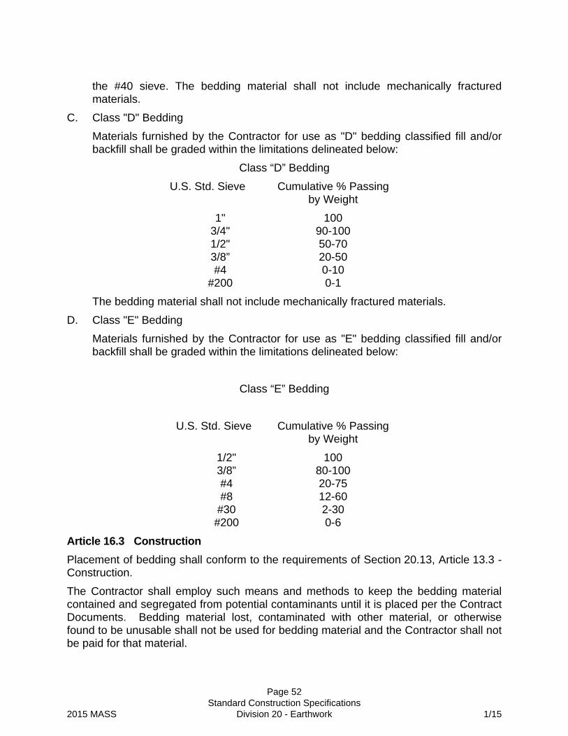
Page 52 Standard Construction Specifications 2015 MASS Division 20 - Earthwork 1/15
the #40 sieve. The bedding material shall not include mechanically fractured materials.
C. Class "D" Bedding
Materials furnished by the Contractor for use as "D" bedding classified fill and/or backfill shall be graded within the limitations delineated below:
Class “D” Bedding
U.S. Std. Sieve Cumulative % Passing by Weight
1" 100 3/4" 90-100 1/2" 50-70 3/8” 20-50 #4 0-10
#200 0-1
The bedding material shall not include mechanically fractured materials.
D. Class "E" Bedding
Materials furnished by the Contractor for use as "E" bedding classified fill and/or backfill shall be graded within the limitations delineated below:
Class “E” Bedding
U.S. Std. Sieve Cumulative % Passing by Weight
1/2" 100 3/8” 80-100 #4 20-75 #8 12-60
#30 2-30 #200 0-6
Article 16.3 Construction
Placement of bedding shall conform to the requirements of Section 20.13, Article 13.3 - Construction.
The Contractor shall employ such means and methods to keep the bedding material contained and segregated from potential contaminants until it is placed per the Contract Documents. Bedding material lost, contaminated with other material, or otherwise found to be unusable shall not be used for bedding material and the Contractor shall not be paid for that material.
Page 53 Standard Construction Specifications 2015 MASS Division 20 - Earthwork 1/15
Article 16.4 Measurement
Measurement of bedding shall be per ton or per linear foot of bedding material placed in the trench.
Article 16.5 Basis of Payment
Payment for this Work shall be in accordance with Division 10, Section 10.07 - Measurement and Payment, and shall include full payment for all Work described in this Section.
Payment shall be made under the following units:
ITEM UNIT
Bedding Material (Class) Ton
Bedding Material (Class) Linear Foot

Page 54 Standard Construction Specifications 2015 MASS Division 20 - Earthwork 1/15
SECTION 20.17 FURNISH FILTER MATERIAL
Article 17.1 General
This Work under this Section consists of performance of all operations pertaining to providing filter material.
Article 17.2 Materials
Filter material shall be gravel or sand consisting of crushed or naturally-occurring granular material. It shall be free of clay particles and conforming to the gradation requirements below.
The coarse aggregate material conforming to the requirements specified below shall have a percentage of wear not to exceed thirty (30) after five hundred (500) revolutions, as determined by the current requirements of ASTM C-131.
Requirements for Grading of Filter Material:
Gradation (% Passing)
Sieve 2” 1-1/2” 1” 3/4" 1/2" 3/8” #4 #16 #50 #100 #200
Type A 100 95-100 45-80 10-30 0-10 0-3
Type B 100 0-5
Type C 100 95-100 0-20 0-5
Type D 100 90-100 50-70 20-50 0-5 0-1
Foundry sand and other material which may be cementitous or not suitable for water percolation shall not be used.
Article 17.3 Construction
Filter material is defined as the material which is placed below, above, and on each side of a perforated pipe to form a subdrain. Filter material may also be used directly in the trenches without a perforated pipe to form a French drain. Refer to Standard Detail 55-3 for construction of a subdrain.
Article 17.4 Measurement
Measurement of filer material shall be per ton or per linear foot of material placed in the trench.
Article 17.5 Basis of Payment
Payment for this Work shall be in accordance with Division 10, Section 10.07 - Measurement and Payment, and shall include full payment for all Work described in this Section.
Payment for placing filter material for French drains is included in Section 20.13 - Trench Excavation and Backfill. Payment for furnishing and placing filter material for subdrains is included in payment for Division 55, Section 55.03 - Subdrains. Payment for this item includes furnishing the required type of filter material.
Payment shall be made under the following unit:
ITEM UNIT
Filter Material (Type) Ton
Filter Material (Type) Linear Foot

Page 55 Standard Construction Specifications 2015 MASS Division 20 - Earthwork 1/15
SECTION 20.18 DRAIN/FILTER ROCK
Article 18.1 General
The Work under this Section consists of performing all operations pertaining to furnishing and placing a layer of drain/filter rock as shown on the plans or as directed by the Engineer.
Article 18.2 Materials
Materials furnished by the Contractor for drain/filter rock shall be graded within the limitations delineated below:
Drain/Filter Rock
U.S. Std. Sieve Cumulative % Passing by Weight
Drain Rock Filter Rock
8” 100 -
6” 50-80 100
4” 25-50 50-80
3” 0-25 -
2” 0-10
1” - 0-10
#200 0-1 0-1
Article 18.3 Construction
The drain/filter rock shall be handled, dumped, or spread into place so as to secure a stone mass of the dimensions shown on the Drawings.
Article 18.4 Measurement
Drain/filter rock shall be measured in tons complete and accepted in place.
Article 18.5 Basis of Payment
Payment for this Work shall be in accordance with Division 10, Section 10.07 - Measurement and Payment, and shall include full payment for all Work described in this Section.
Payment shall be made under the following unit:
ITEM UNIT
Drain Rock Ton
Filter Rock Ton

Page 56 Standard Construction Specifications 2015 MASS Division 20 - Earthwork 1/15
SECTION 20.19 FURNISH FOUNDATION BACKFILL
Article 19.1 General
The Work under this Section consists of performing all operations necessary for excavation, backfilling, compacting foundation materials and trenches.
Article 19.2 Materials
Foundation material for backfill shall consist of Type II, II-A, III, V, or VI classified backfill as specified in the Contract Documents or by the Engineer.
Article 19.3 Construction
If the trench material at the bottom of bedding does not furnish a suitable foundation, the Contractor shall remove the unsuitable material to whatever depth the Engineer determines and replace with foundation material from borrow. Foundation material shall be placed the full width of trench, in lifts not to exceed twelve inches (12") in thickness and compacted to a minimum of ninety-five percent (95%) of maximum density.
In the event of unauthorized over-excavation, the Contractor shall backfill with foundation material to the proper grade and compact to a minimum of ninety-five percent (95%) of maximum density for the full length of the over-excavated trench, all at no additional expense to the Owner.
Article 19.4 Measurement
Where the Contractor is ordered to remove unsuitable material below grade and replace it with foundation material, the material shall be paid for on a cubic yard or ton basis.
Article 19.5 Basis of Payment
Payment for the Work shall be in accordance with Division 10, Section 10.07 - Measurement and Payment, and shall include full payment for all Work described in this Section.
Payment shall be made under the following units:
ITEM UNIT
Foundation Backfill (Type) Cubic Yard
Foundation Backfill (Type) Ton
Page 57 Standard Construction Specifications 2015 MASS Division 20 - Earthwork 1/15
SECTION 20.20 UNCLASSIFIED FILL AND BACKFILL
Article 20.1 General
The Work under this Section consists of furnishing all plant, labor, equipment, supplies, and material in performance of all operations pertaining to the excavation, stockpiling on site, and placement of Unclassified Fill and Backfill.
Article 20.2 Material
Unclassified Fill and Backfill shall be defined as excavated non-organic material that is determined by the Engineer to be unsuitable for Classified Fill and Backfill and suitable for deposition in non-structural fill zones.
Article 20.3 Construction
Excavated material not conforming to the specifications of Section 20.21 - Classified Fill and Backfill shall be used as Unclassified Fill and Backfill adjacent to the fill-slopes to provide additional slope stability to the fill-slopes. Excess Unclassified Fill and Backfill not used shall be disposed of at a Contractor-furnished disposal site as delineated in Division 10, Section 10.04, Article 4.9 – Disposal Sites.
Article 20.4 Measurement
The measurement of excavation will not include water or other liquids, but will include topsoil, mud, muck, or other similar semi-solid material which cannot be drained or pumped away.
Unclassified Fill and Backfill will be measured per cubic yard by cross section.
Cross section measurement of Unclassified Fill and Backfill shall be based on in-place volumes as determined by the average end areas of cross sections.
Article 20.5 Basis of Payment
Payment for this Work shall be in accordance with Division 10, Section 10.07 - Measurement and Payment, and shall include full payment for all Work described in this Section.
Payment shall be made under the following unit:
ITEM UNIT
Unclassified Fill and Backfill Cubic Yard

Page 58 Standard Construction Specifications 2015 MASS Division 20 - Earthwork 1/15
SECTION 20.21 CLASSIFIED FILL AND BACKFILL
Article 21.1 General
The Work under this Section consists of performing all operations necessary to furnish, place, and compact classified fill and backfill.
Article 21.2 Material
Classified fill and backfill shall contain no lumps, frozen material, organic matter, or other deleterious matter, and shall be durable and sound. It shall have a plasticity index not greater than six (6) as determined by ASTM D-424 and shall conform to one of the following types as required by the Drawings and Specifications. The coarse aggregate material conforming to the requirements specified below shall have a percentage of wear not to exceed thirty (30) after five hundred (500) revolutions, as determined by the current requirements of ASTM C-131.
The portion of the material retained on a #4 sieve shall be known as coarse aggregate. Both coarse and fine aggregates shall conform to the quality requirements of AASHTO M-147.
A. Type II
Materials furnished by the Contractor for use as Type II classified fill and/or backfill shall be graded within the limitations delineated below:
Type II
U.S. Std. Sieve Cumulative % Passing
by Weight
8" 100 3" 70-100
1-1/2" 55-100 3/4" 45-85 #4 20-60
#10 12-50 #40 4-30 #200 2-6
* In addition to the grading limits listed above, the fraction of material passing the #200 sieve shall not be greater than fifteen percent (15%) of that fraction passing the #4 sieve.
B. Type II-A
Materials furnished by the Contractor for use as Type II-A classified fill and/or backfill shall be graded within the limitations delineated below:

Page 59 Standard Construction Specifications 2015 MASS Division 20 - Earthwork 1/15
Type II-A
U.S. Std. Sieve Cumulative % Passing by Weight
3" 100 3/4" 50-100 #4 25-60
#10 15-50 #40 4-30 #200 2-6
* In addition to the grading limits listed above, the fraction of material passing the #200 sieve shall not be greater than twenty percent (20%) of that fraction passing the #4 sieve.
C. Type III
Materials furnished by the Contractor for use as Type III classified fill and/or backfill shall be approved sand or gravel with a maximum of ten percent (10%) passing the #200 sieve.
D. Type IV
Materials furnished by the Contractor for use as Type IV classified fill and/or backfill shall be an approved material consisting of sand or gravel with a maximum of twenty-five percent (25%) passing the #200 sieve.
E. Type V
Materials furnished by the Contractor for use as Type V classified fill and/or backfill shall be graded within the limitations delineated below:
Type V
U.S. Std. Sieve Cumulative % Passing by Weight
3” 100 1 1/2" 60-90 3/4" 40-80 #4 25-55
#10 15-45 #40 4-30 #200 2-6
* In addition to the grading limits listed above, at least thirty percent (30%) of the coarse aggregate particles shall have one or more mechanically fractured face.
F. Type VI
Materials furnished by the Contractor for use as Type VI classified fill and/or backfill shall be graded within the limitations delineated below:
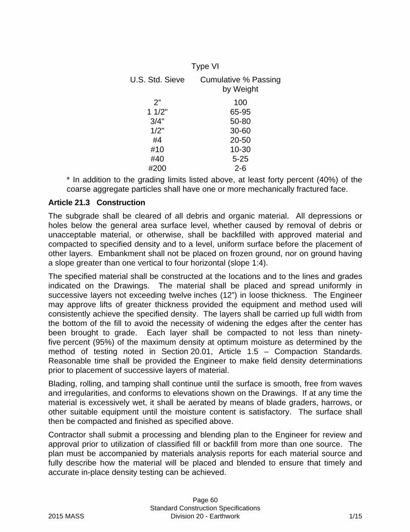
Page 60 Standard Construction Specifications 2015 MASS Division 20 - Earthwork 1/15
Type VI
U.S. Std. Sieve Cumulative % Passing by Weight
2” 100 1 1/2" 65-95 3/4" 50-80 1/2" 30-60 #4 20-50
#10 10-30 #40 5-25 #200 2-6
* In addition to the grading limits listed above, at least forty percent (40%) of the coarse aggregate particles shall have one or more mechanically fractured face.
Article 21.3 Construction
The subgrade shall be cleared of all debris and organic material. All depressions or holes below the general area surface level, whether caused by removal of debris or unacceptable material, or otherwise, shall be backfilled with approved material and compacted to specified density and to a level, uniform surface before the placement of other layers. Embankment shall not be placed on frozen ground, nor on ground having a slope greater than one vertical to four horizontal (slope 1:4).
The specified material shall be constructed at the locations and to the lines and grades indicated on the Drawings. The material shall be placed and spread uniformly in successive layers not exceeding twelve inches (12”) in loose thickness. The Engineer may approve lifts of greater thickness provided the equipment and method used will consistently achieve the specified density. The layers shall be carried up full width from the bottom of the fill to avoid the necessity of widening the edges after the center has been brought to grade. Each layer shall be compacted to not less than ninety-five percent (95%) of the maximum density at optimum moisture as determined by the method of testing noted in Section 20.01, Article 1.5 – Compaction Standards. Reasonable time shall be provided the Engineer to make field density determinations prior to placement of successive layers of material.
Blading, rolling, and tamping shall continue until the surface is smooth, free from waves and irregularities, and conforms to elevations shown on the Drawings. If at any time the material is excessively wet, it shall be aerated by means of blade graders, harrows, or other suitable equipment until the moisture content is satisfactory. The surface shall then be compacted and finished as specified above.
Contractor shall submit a processing and blending plan to the Engineer for review and approval prior to utilization of classified fill or backfill from more than one source. The plan must be accompanied by materials analysis reports for each material source and fully describe how the material will be placed and blended to ensure that timely and accurate in-place density testing can be achieved.

Page 61 Standard Construction Specifications 2015 MASS Division 20 - Earthwork 1/15
The maximum dimensions of any particle of the embankment material shall not be greater than two-thirds (2/3) of the compacted thickness of the layer in which it is placed unless specified elsewhere. The top six inches (6”) of embankment material for roads, streets, parking lots, and bike trails, shall be Type II-A classified fill and backfill. Oversize material shall be removed. Portions of any layer in which the embankment material becomes segregated shall be removed and replaced with satisfactory material or shall be added to and remixed to secure proper gradation as directed by the Engineer. No separate payment will be made for any material removed or regraded in areas where material becomes segregated.
The Engineer may permit lifts in excess of twelve inch (12") thickness when classified fill or backfill is placed over swampy or saturated ground, or where he is satisfied that the Contractor's method and equipment will consistently produce the specified density.
Embankments for bike trail sections will be brought to grade in one (1) single lift for embankments less than eighteen inches (18”) to finish grade. Trail embankments over eighteen inches (18”) shall be brought to grade in lifts as directed by the Engineer.
Article 21.4 Measurement
Classified fill or backfill material, obtained from borrow pits, will be measured in tons (2000 lbs.) of material delivered and placed in accordance with these Specifications. The measurement may include moisture up to a maximum of four percent (4.0%) of dry weight of the material. When tests by the Engineer indicate that moisture contents in excess of four percent (4.0%) may be occurring consistently, the frequency of testing will be increased as necessary and the results averaged over a period of one week. When this average is greater than four percent (4.0%), the tonnage as measured over the above period, shall be reduced by the difference. No credit will be due the Contractor when moisture content is less than four percent (4.0%). Testing shall be done in accordance with Section 20.01, Article 1.3 – Applicable Standards.
Imported classified fill and backfill will be weighed on a scale certified by the State of Alaska. Weight tickets will be serialized and witnessed at the time of weighing by a Contractor-furnished weighman. The Engineer may at any time verify load weights and the weighing process.
Where excavation of unsuitable material beyond the lines and grades shown on the Drawings is ordered in writing, the measurement of classified backfill will include the material required for replacement. No measurement will be made for quantities placed beyond the lines and grade authorized or for quantities placed outside the limits of required excavation.
The Contractor and the Engineer shall verify daily the quantity of material delivered to the Project site. Weight tickets not presented at time of delivery will require special verification by the Contractor before payment can be made.

Page 62 Standard Construction Specifications 2015 MASS Division 20 - Earthwork 1/15
Article 21.5 Basis of Payment
Payment for this Work shall be in accordance with Division 10, Section 10.07 - Measurement and Payment, and shall include full payment for all Work described in this Section.
Payment for the placement and compaction of usable excavation shall not be paid under this Section.
Payment shall be made under the following units:
ITEM UNIT
Classified Fill and Backfill (Type) Ton
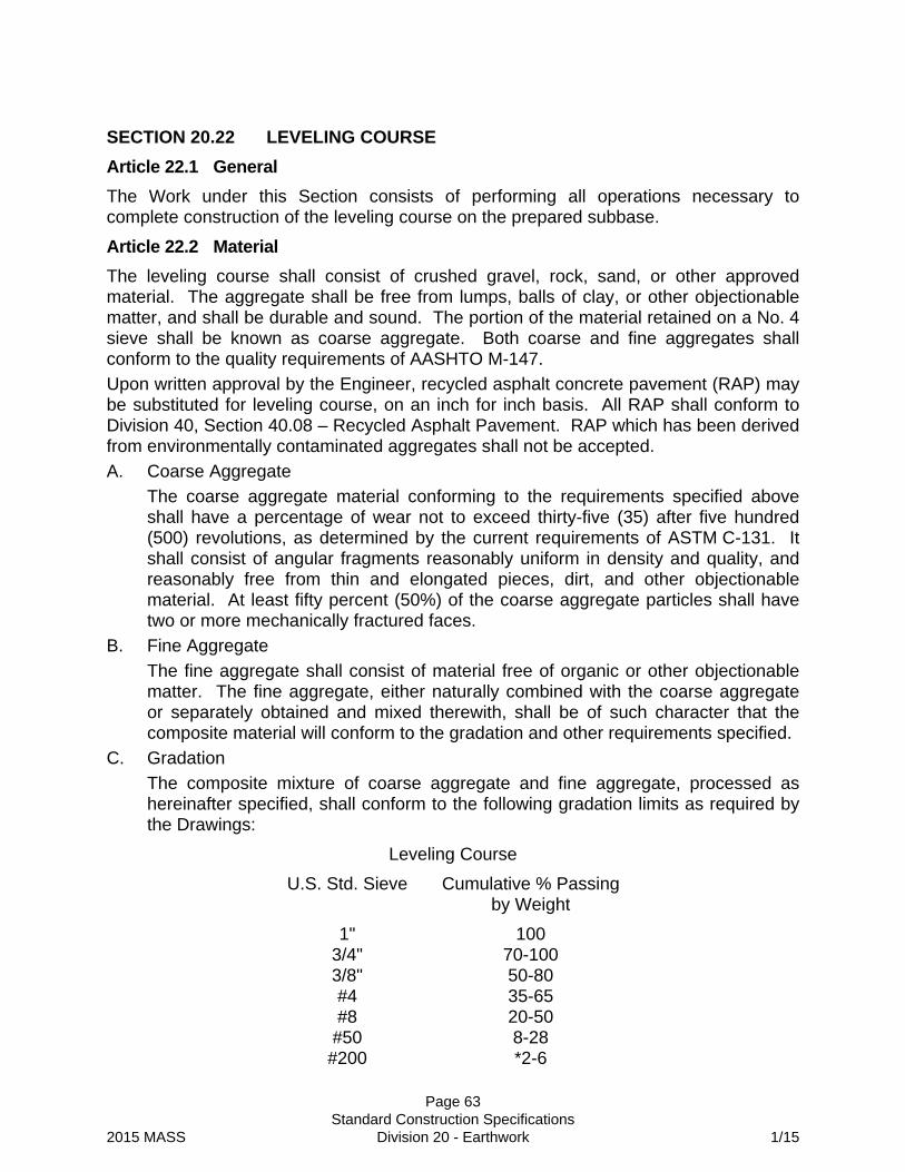
Page 63 Standard Construction Specifications 2015 MASS Division 20 - Earthwork 1/15
SECTION 20.22 LEVELING COURSE
Article 22.1 General
The Work under this Section consists of performing all operations necessary to complete construction of the leveling course on the prepared subbase.
Article 22.2 Material
The leveling course shall consist of crushed gravel, rock, sand, or other approved material. The aggregate shall be free from lumps, balls of clay, or other objectionable matter, and shall be durable and sound. The portion of the material retained on a No. 4 sieve shall be known as coarse aggregate. Both coarse and fine aggregates shall conform to the quality requirements of AASHTO M-147.
Upon written approval by the Engineer, recycled asphalt concrete pavement (RAP) may be substituted for leveling course, on an inch for inch basis. All RAP shall conform to Division 40, Section 40.08 – Recycled Asphalt Pavement. RAP which has been derived from environmentally contaminated aggregates shall not be accepted.
A. Coarse Aggregate
The coarse aggregate material conforming to the requirements specified above shall have a percentage of wear not to exceed thirty-five (35) after five hundred (500) revolutions, as determined by the current requirements of ASTM C-131. It shall consist of angular fragments reasonably uniform in density and quality, and reasonably free from thin and elongated pieces, dirt, and other objectionable material. At least fifty percent (50%) of the coarse aggregate particles shall have two or more mechanically fractured faces.
B. Fine Aggregate
The fine aggregate shall consist of material free of organic or other objectionable matter. The fine aggregate, either naturally combined with the coarse aggregate or separately obtained and mixed therewith, shall be of such character that the composite material will conform to the gradation and other requirements specified.
C. Gradation
The composite mixture of coarse aggregate and fine aggregate, processed as hereinafter specified, shall conform to the following gradation limits as required by the Drawings:
Leveling Course
U.S. Std. Sieve Cumulative % Passing by Weight
1" 100 3/4" 70-100 3/8" 50-80 #4 35-65 #8 20-50
#50 8-28 #200 *2-6

Page 64 Standard Construction Specifications 2015 MASS Division 20 - Earthwork 1/15
*In addition to the grading limits stipulated above, fractions passing the #200 sieve shall not be greater than seventy-five percent (75%) of the fractions passing the #50 sieve.
Article 22.3 Construction
The leveling course shall be placed to the lines, grades, and thicknesses shown on the Drawings and shall consist of the materials hereinbefore specified. The leveling course shall provide a smooth stabilized surface on which to place the pavement.
A. Preparation of Subbase
Subbase preparation shall consist of dressing, shaping, wetting, and compacting of the subbase to a minimum density of ninety-five percent (95%) in accordance with Section 20.01, Article 1.5 - Compaction Standards. Surfaces shall be cleaned of all foreign substances and debris. Any ruts or soft yielding spots that may appear in the subbase surface shall be corrected by loosening, removing and adding approved material, reshaping, and recompacting the affected areas to the line, grade, and to the specified density requirements.
B. Surveying
Subbase and leveling course control stakes shall be wooden bluetops set to finish subbase. The subbase bluetops will be the reference used by the Contractor to set top of leveling course. Subbase bluetops shall be set at breaks in grade and on even grade at intervals not to exceed fifty feet (50’), with additional stakes at vertical curves. Side control will be from the lip or gutter, or in the case of strip paving, additional bluetops shall be provided.
C. Placing
The approved leveling course material shall be deposited and spread in a uniform layer to the required contour and grades and to such loose depth that when compacted to the density required will achieve the specified thickness. The material shall be spread uniformly on the prepared subbase from moving vehicles or spreading boxes, then leveled to the required contour and graded with blade graders. Portions of the layer which become segregated in spreading shall be remixed to the required gradation.
D. Compacting
The leveling course shall be compacted to a minimum of ninety-five percent (95%) of maximum density. In all places not accessible to the rolling equipment, the mixture shall be compacted with tamping equipment. Blading, rolling and tamping shall continue until the surface is smooth and free from waves and inequalities. If at any time the mixture is excessively moistened by rain, it shall be aerated by means of blade graders, harrows or other approved equipment until the moisture content is such that the surface can be recompacted and finished as above. The finished leveling course shall be maintained by the Contractor in the above condition until the pavement is applied.

Page 65 Standard Construction Specifications 2015 MASS Division 20 - Earthwork 1/15
E. Smoothness Test
The surface of the leveling course, when finished, shall not show any deviation in excess of three-eighths inch (3/8”) when tested with a ten foot (10’) straightedge applied parallel with, and at right angles to, the centerline of the area to be paved. Any deviation in excess of this amount shall be corrected by loosening, adding, or removing material and reshaping and compacting to satisfy the above requirement.
Contractor shall obtain written approval from the Engineer for the final leveling course grade prior to pavement placement.
Article 22.4 Measurement
The leveling course shall be measured in tons of materials delivered and placed in accordance with these Specifications . The measurement may include moisture up to a maximum of four percent (4.0%) of dry weight of the material. When tests by the Engineer indicate that moisture contents in excess of four percent (4.0%) may be occurring consistently, the frequency of testing will be increased as necessary and the results averaged over a period of one week. When this average is greater than four percent (4.0%), the tonnage as measured over the above period, shall be reduced by the difference. No credit will be due the Contractor when moisture content is less than four percent (4.0%). Testing shall be done in accordance with Section 20.01, Article 1.3 – Applicable Standards.
Article 22.5 Basis of Payment
Payment for this Work shall be in accordance with Division 10, Section 10.07 - Measurement and Payment, and shall include full payment for all Work described in this Section.
Payment shall be made under the following unit:
ITEM UNIT
Leveling Course Ton

Page 66 Standard Construction Specifications 2015 MASS Division 20 - Earthwork 1/15
SECTION 20.23 COBBLES
Article 23.1 General
The Work under this Section consists of performing all operations pertaining to furnishing and placing a layer of cobbles as shown on the Drawings or as directed by the Engineer.
Article 23.2 Materials
Materials furnished by the Contractor for cobbles shall be graded within the limitations delineated below:
Cobbles
U.S. Std. Sieve Cumulative % Passing
by Weight
12” 100
8” 50-80
6” 25-50
3” 0-25
2” 0-10
#200 0-1
Article 23.3 Construction
The cobbles shall be handled, dumped, or spread into place so as to secure a stone mass of the dimensions shown on the Drawings.
Article 23.4 Measurement
Cobbles shall be measured in tons complete and accepted in place.
Article 23.5 Basis of Payment
Payment for this Work shall be in accordance with Division 10, Section 10.07 - Measurement and Payment, and shall include full payment for all Work described in this Section.
Payment shall be made under the following unit:
ITEM UNIT
Cobbles Ton
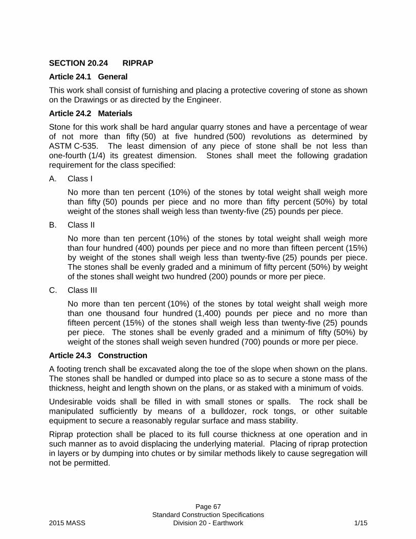
Page 67 Standard Construction Specifications 2015 MASS Division 20 - Earthwork 1/15
SECTION 20.24 RIPRAP
Article 24.1 General
This work shall consist of furnishing and placing a protective covering of stone as shown on the Drawings or as directed by the Engineer.
Article 24.2 Materials
Stone for this work shall be hard angular quarry stones and have a percentage of wear of not more than fifty (50) at five hundred (500) revolutions as determined by ASTM C-535. The least dimension of any piece of stone shall be not less than one-fourth (1/4) its greatest dimension. Stones shall meet the following gradation requirement for the class specified:
A. Class I
No more than ten percent (10%) of the stones by total weight shall weigh more than fifty (50) pounds per piece and no more than fifty percent (50%) by total weight of the stones shall weigh less than twenty-five (25) pounds per piece.
B. Class II
No more than ten percent (10%) of the stones by total weight shall weigh more than four hundred (400) pounds per piece and no more than fifteen percent (15%) by weight of the stones shall weigh less than twenty-five (25) pounds per piece. The stones shall be evenly graded and a minimum of fifty percent (50%) by weight of the stones shall weight two hundred (200) pounds or more per piece.
C. Class III
No more than ten percent (10%) of the stones by total weight shall weigh more than one thousand four hundred (1,400) pounds per piece and no more than fifteen percent (15%) of the stones shall weigh less than twenty-five (25) pounds per piece. The stones shall be evenly graded and a minimum of fifty (50%) by weight of the stones shall weigh seven hundred (700) pounds or more per piece.
Article 24.3 Construction
A footing trench shall be excavated along the toe of the slope when shown on the plans. The stones shall be handled or dumped into place so as to secure a stone mass of the thickness, height and length shown on the plans, or as staked with a minimum of voids.
Undesirable voids shall be filled in with small stones or spalls. The rock shall be manipulated sufficiently by means of a bulldozer, rock tongs, or other suitable equipment to secure a reasonably regular surface and mass stability.
Riprap protection shall be placed to its full course thickness at one operation and in such manner as to avoid displacing the underlying material. Placing of riprap protection in layers or by dumping into chutes or by similar methods likely to cause segregation will not be permitted.

Page 68 Standard Construction Specifications 2015 MASS Division 20 - Earthwork 1/15
All material going into riprap protection shall be so placed and distributed that there will be no large accumulation or area composed largely of either the larger or smaller sizes of stone.
Unless otherwise authorized by the Engineer, the riprap protection shall be placed in conjunction with the construction of the embankment with only sufficient lag in construction of the riprap protection as may be necessary to prevent mixture of embankment and riprap material.
The Contractor shall provide a level compact area of sufficient size to dump and sort typical loads of riprap at approved location(s). He shall further dump loads specified in this area and assist the Engineer as needed to sort and measure the stones in the load for the purpose of determining if the riprap is within specifications. Mechanical equipment as needed to assist in this sorting shall be provided by the Contractor at no additional cost to the Owner.
Article 24.4 Method of Measurement
Riprap shall be measured in cubic yards measured by neat line measure, or tons, completed and accepted in place. Excavation and backfill required for placement of riprap is considered incidental to the bid item.
Article 24.5 Basis of Payment
Payment for this Work shall be in accordance with Division 10, Section 10.07 - Measurement and Payment, and shall include full payment for all Work described in this Section.
When more than one class of riprap is specified for any pay item, letter suffixes shall be included within the parentheses of the item numbers in order to differentiate between the different classes.
Payment will be made under the following item:
ITEM UNIT
Riprap (Class) Cubic Yard
Riprap (Class) Ton

Page 69 Standard Construction Specifications 2015 MASS Division 20 - Earthwork 1/15
SECTION 20.25 GEOTEXTILE FABRIC
Article 25.1 Description
The Work under this Section shall consist of furnishing and installing Geotextile Fabric for embankment separation, subgrade reinforcement of roadways, subsurface drainage, or riprap lining in a manner and at locations as shown in the Drawings or as directed by the Engineer.
Article 25.2 Materials
Geotextile fabrics furnished as required in the Drawings shall meet conform to the following specifications, based on AASHTO M288-06. Additional requirements follow depending on the application of the geotextile fabric.
Geotextile Class a,b
Class 1 Class 2
Property Test Methods Units
Woven Elongation
< 50% c
Non-Woven
Elongation 50% c
Woven Elongation
< 50% c
Non-Woven Elongation 50% c
Grab Strength ASTM D 4632
Lbs (#) 315 200 250 160
Sewn Seam Strength
ASTM D 4632
Lbs (#) 285 182 225 140
Tear Strength ASTM D 4533
Lbs (#) 115 80 90 56
Puncture Strength
ASTM D 6241
Lbs (#) 620 435 495 310
a The severity of installation conditions for the application generally dictates the required geotextile class. Class 1 is specified for more severe or harsh installation conditions where there is greater potential for geotextile damage. Class 2 is specified for less severe conditions. b All numeric values represent MARV in the weaker principal direction. c As measured in accordance with ASTM D 4632.
A. Type A Geotextile (Separation)
Type A Geotextile is used for separation. The Type A Geotextile shall be a woven or nonwoven pervious fabric constructed from long chain polymeric filaments such as polypropylene, polyethylene, polyester, polyvinylidene chloride or polyamide formed into a stable network such that the filaments or yarns retain their relative position to each other. The geotextile shall be inert to commonly encountered chemicals and shall be free from defects.
Non-woven geotextile may be formed by the needle-punched, spun-bonded or melt-bonded process.

Page 70 Standard Construction Specifications 2015 MASS Division 20 - Earthwork 1/15
Woven geotextile shall be a pervious sheet of yarn woven into a uniform pattern with distinct and measurable openings. Edges of the cloth shall be salvaged to prevent the outer yarn from pulling away from the cloth.
Acceptance of geotextile material is to be determined according to ASTM D-4873.
Geotextile manufacturer shall provide a letter certifying that its geotextile product meets the specified requirements.
Type A Geotextile supplied shall be Class 2, unless otherwise specified in the Contract Documents and shall meet the physical and mechanical properties listed below:
Property Test
Methods Units Requirements
Permittivity ASTM D 4491
Sec -1 0.02 a
Apparent Opening Size
ASTM D 4751
mm 0.60 max avg roll value
Ultraviolet stability (retained strength)
ASTM D 4355
% 50% after 500 h of exposure
a Default value. Permittivity of the geotextile should be greater than that of the soil. The Engineer may also require the permeability of the geotextile to be greater than that of the soil.
B. Type B Geotextile (Reinforcement)
Type B Geotextile is used for reinforcement. Type B Geotextile shall consist of a regular grid structure formed by biaxially drawing a continuous sheet of select polypropylene material; it shall have aperture geometry and rib and junction cross sections sufficient to permit significant mechanical interlock with the material being reinforced.
Type B Geotextile shall have high flexural rigidity and high tensile strength at ribs and junctions of the grid structure.
Type B Geotextile shall maintain its reinforcement and interlock capabilities under repeated dynamic loads while in service and shall also be resistant to ultraviolet degradation, to damage under normal practices, and to all forms of biological or chemical degradation normally encountered in the material being reinforced.
Type B Geotextile supplied shall be Class 1 unless otherwise specified in the Contract Documents and shall meet the physical and mechanical properties listed below:

Page 71 Standard Construction Specifications 2015 MASS Division 20 - Earthwork 1/15
Property Test
Methods Units Requirements
Permittivity ASTM D 4491
Sec -1 0.05 a
Apparent Opening Size
ASTM D 4751
mm 0.43 max avg roll value
Ultraviolet stability (retained strength)
ASTM D 4355
% 50% after 500 h of exposure
a Default value. Permittivity of the geotextile should be greater than that of the soil. The Engineer may also require the permeability of the geotextile to be greater than that of the soil.
C. Type C Geotextile (Drainage/Riprap Lining)
Type C Geotextile is used for drainage or riprap lining. The geotextile shall be constructed from long chain polymeric filament or yarns such as polypropylene, polyethylene, polyester, nylon, polyvinylidene chloride or polyamide formed into a stable network such that the filaments or yarns retain their relative position to each other. The geotextile shall be inert to commonly encountered chemicals and shall be free from defects.
Non-woven geotextile may be formed by the needle punched, spun-bonded or melt-bonded process.
Woven geotextile shall be a pervious sheet of yarn woven into a uniform pattern with distinct and measurable openings. Edges of the cloth shall be salvaged to prevent the outer yarn from pulling away from the cloth.
Geotextiles made from yarns of a flat, tape-like character are not allowed.
Type C Geotextile supplied shall be Class 2, unless otherwise specified in the Contract Documents and shall meet the physical and mechanical properties listed below:
Requirements
Percent in Situ Soil Passing #25 Sieve a (0.075mm)
Property Test Methods Units < 15 15 to 50 > 50
Permittivity ASTM D 4491
Sec -1 0.5 0.2 0.1
0.43 .25 .22 Apparent Opening Size
ASTM D 4751
mm
max. avg roll value
Ultraviolet stability (retained strength)
ASTM D 4355
% 50% after 500 h of exposure
a Based on grain size analysis of in situ soil in accordance with AASHTO T88.
Acceptance of geotextile material shall be determined according to ASTM D-4759.

Page 72 Standard Construction Specifications 2015 MASS Division 20 - Earthwork 1/15
D. Submittal Requirements
The Contractor shall submit the following information to the Engineer for review and acceptance:
1. Full-scale laboratory testing and in-ground testing of pavement structures reinforced with the proposed geotextile product which illustrates significant structural contribution of the geotextile product to the pavement structure.
2. Certified test results stating that the geotextile product meets the material and physical properties in all respects.
3. Guidelines to pavement design using proposed geotextile product.
4. A list of not less than ten (10) comparable projects, in terms of size and application, in the United States, with references and phone numbers, where the results of the proposed geotextile product’s use can be verified after a minimum of three years continuous service life.
5. Geotextile product samples and certified material property data sheets.
6. Recommended installation instructions.
7. Geotextile manufacturer shall provide a letter certifying that its geotextile product meets the specified requirements.
Article 25.3 Construction
A. Surface Preparation
Prepare surface by removal of stumps, boulders, and sharp objects in accordance with Section 20.05 - Clearing. Contractor shall fill holes and large ruts with material shown on the Drawings or as approved by the Engineer.
Clearing shall be considered incidental to this item. Material used to fill ruts and holes shall be paid for at the unit price for the type of material used, as shown on the Drawings or as approved by the Engineer.
In Areas to Be Surcharged: All trees and brush having a trunk base diameter greater than one-half inch (1/2”) shall be cut to within two inches (2”) of original ground surface. Grass shall be flattened with no more than two passes of a tracked vehicle.
B. Geotextile Placement
Unroll geotextile directly onto the prepared surface. Exposure of geotextile to the elements after removal of protective covering shall not exceed five days.
Unroll geotextile for embankment reinforcement parallel to the embankment centerline.
Geotextile shall be placed in daily work sections so the lap adjustment can be made should movement of the geotextile occur during placement of fill.

Page 73 Standard Construction Specifications 2015 MASS Division 20 - Earthwork 1/15
C. Joining
1. Type A Geotextile
Fabric shall be joined with adjacent pieces of fabric by sewing or overlapping.
If fabric is sewn, the fabric shall have all seams sewn by butterfly or J-seams and shall develop a minimum of eighty-five percent (85%) of the specified strength. Seams shall be sewn with a double-thread chain-lock stitch. High strength polyester, polypropylene or Kevlar thread shall be used. The seam shall be one and one-half inch plus or minus one-quarter inch (1-1/2” 1/4”) from the outside edge of the geotextile.
2. Type B Geotextile
Sections shall be overlapped a minimum of three feet (3’), or as shown on the Drawings, to prevent shifting of geotextile during installation and filling.
Lap joints shall be tied with plastic ties specifically manufactured for this purpose at five foot (5’) intervals.
3. Type C Geotextile
Fabric shall be joined with adjacent pieces of fabric by sewing or overlapping.
If fabric is sewn, the fabric shall have all seams sewn by butterfly or J-seams and shall develop a minimum of eighty-five percent (85%) of the specified strength. Seams shall be sewn with a double-thread chain-lock stitch. High strength polyester, polypropylene or Kevlar thread shall be used. The seam shall be one and one-half inch plus or minus one-quarter inch (1-1/2” 1/4”) from the outside edge of the geotextile. If the fabric is overlapped, the sections shall be overlapped a minimum of three feet (3’) or as shown on the Drawings.
D. Material Placing and Spreading
Fill material placement shall not occur until the Engineer accepts surface preparation and geotextile laps.
Contractor shall maintain minimum laps and fabric continuity without fabric loops or kinks during material placement and spreading.
Follow the manufacturer’s recommendations for material placing and spreading of the geotextile. During placing and spreading, the Contractor shall maintain a minimum depth of one foot (1’) of cover material at all times between the fabric and the wheels or tracks of the construction equipment. At no time shall equipment operate on the unprotected geotextile. Construction equipment shall not make sudden stops, starts, or turns on the over material. Use a smooth drum roller to achieve the specified density.
Spread the material in the direction of the fabric overlap.
On weak subgrades, spread the cover material simultaneously with dumping to minimize the potential of a localized subgrade failure.

Page 74 Standard Construction Specifications 2015 MASS Division 20 - Earthwork 1/15
E. Geotextile Repair
Should it be determined during or after embankment construction that specified geotextile lap widths have not been achieved, or that the Contractor otherwise damaged the installed geotextile, the Contractor shall correct the geotextile installation at no additional cost to the Municipality.
The Contractor shall expose the geotextile and add additional geotextile extending in all directions to achieve specified laps and anchorage. After correcting the geotextile, the embankment shall be reconstructed in accordance with the Contract Documents.
Article 25.4 Method of Measurement
Geotextile shall be measured in square yards of ground surface covered by fabric as shown on the Drawings or as approved by the Engineer. Overlapping and stitching of fabric will be considered incidental to this pay item and no additional payment will be made.
Material used to fill ruts and holes shall be paid for at the unit price of the appropriate bid item for the type material used, as shown on the Drawings or as approved by the Engineer.
Article 25.5 Basis of Payment
Payment for this Work shall be in accordance with Division 10, Section 10.07 - Measurement and Payment, and shall include full payment for all Work described in this Section.
Payment shall be made under the following unit:
ITEM UNIT
Geotextile (Type) Square Yard

Page 75 Standard Construction Specifications 2015 MASS Division 20 - Earthwork 1/15
SECTION 20.26 INSULATION
Article 26.1 General
The Work under this Section consists of performing all operations including labor and material pertaining to the placement of insulation. Contractor shall provide polystyrene insulation board(s), extruded or expanded, in conformance with the Drawings and these Specifications
The Work under this Section also includes shaping and compacting a level area under the horizontal insulation boards and placing the insulation as indicated on the Drawings.
Article 26.2 Materials
The insulation board shall have a minimum full board size of two foot by eight foot (2' x 8'), have the minimum thickness specified in the Contract Documents, meet the specified R-Value or better, and conform to the requirements of AASHTO M230. R-Value of insulation shall be based on manufacturer’s warranted R-Value. The insulation board shall be rigid, homogeneous, and conform to the following:
Property Test Method Value
Compressive Strength psi, minimum at yield or 5 percent strain
ASTM D-1621 60.0
Water Absorption, maximum percent by volume
ASTM C-272 0.3%
Thermal Resistance, minimum R-Value at 75ºF, ºF-Ft2-Hr/BTU
ASTM C-177 As Specified
Article 26.3 Construction
Contractor shall install the insulation board with staggered joints. Layering of insulation to obtain the specified R-Value is allowed as long as joints are overlapped at least one foot (1’). Contractor shall blade, shape, and compact the area prior to placing the insulation board in accordance with this Division. Contractor shall shape the subgrade to the lines and grades shown on the Drawings and provide a smooth surface on which to place the insulation board. Prior to placing the insulation board on the prepared subgrade, the Contractor shall furnish straightedges to the Inspector for checking surface uniformity. Surface irregularities shall not exceed one inch (1”) within eight feet (8’), or three-eighths inch (3/8”) in two feet (2’). Contractor shall uniformly compact the subgrade. Contractor shall hand-rake smooth and recompact the ridges left by the compaction equipment. Contractor shall accurately set the horizontal insulation boards to the line and grade established and in such a manner as to hold the board firmly in place by mechanically connecting it to the subgrade.
Contractor shall replace or repair insulation panels broken, crushed, or cracked, as determined by the Engineer, at no additional cost to the Owner.
Contractor shall cover the insulation board with approved three inch (3”-) minus Classified Fill and Backfill material, placed in a twelve inch (12”) lift, spread, and compacted for the full width of the insulation layer prior to placing subsequent lifts.
Page 76 Standard Construction Specifications 2015 MASS Division 20 - Earthwork 1/15
Contractor shall place, spread, and compact in such a manner as not to damage the insulation board. Engineer will approve spreading and compacting equipment prior to its use.
Article 26.4 Measurement
The insulation board is measured per square foot regardless of thickness, complete and accepted in place.
Additional Work required for preparing the subgrade to the smoothness required is incidental to the bid item(s) in this Section and no separate payment is made.
Article 26.5 Basis of Payment
Payment for this Work shall be in accordance with Division 10, Section 10.07 - Measurement and Payment, and shall include full payment for all Work described in this Section.
Payment will be made under the following unit:
ITEM UNIT
Insulation Board (R-Value) Square Foot

Page 77 Standard Construction Specifications 2015 MASS Division 20 - Earthwork 1/15
SECTION 20.27 DISPOSAL OF UNUSABLE OR SURPLUS MATERIAL
Article 27.1 General
The Work under this Section consists of performing all operations pertaining to the disposal of unusable or surplus material encountered in the trench excavation. This material may include peat, roots, large rocks, unstabilized soil, cesspools, privy pits, or any other material, which in the opinion of the Engineer is objectionable for use as fill or backfill.
Article 27.2 Construction
The Contractor shall use care in separating unusable material from usable material. When unusable material shall be disposed of, the Engineer will order the same in writing, stating the limitations of the Work. Should the trench be, in the opinion of the Engineer, wider than is necessary for the safety of the workmen, a deduction may be made for the excess width. Payment will not be made for disposal of unusable material unless the material is moved in excess of one hundred feet (100’) from the excavation.
All unusable material shall be hauled to a disposal site provided by the Contractor as delineated in Division 10, Section 10.04, Article 4.9 – Disposal Sites.
Article 27.3 Cesspools, Privy Pits and Septic Tanks
If cesspools and privies are encountered in right-of-way areas and have to be removed to allow construction, the following procedures for removal are to be used. In the case of a privy encountered, the Contractor shall remove the privy from the right-of-way area and set it over onto the private property where the privy belongs. In the case of septic tanks, cesspools and privy pits, the liquid sewage and sludge from the cesspool or privy pit shall be pumped into a watertight container and disposed of at a designated manhole. Care shall be exercised in transporting cesspool and privy pit liquids and sludge so that spillage does not occur during transportation and disposal.
The Contractor shall then remove the remaining sludge, cesspool and privy pit logs or cribbing, and any saturated gravel remaining in the trench area, and shall dispose of this material at the Municipal Landfills. Disposal of this material will be coordinated with the Engineer, in order that the materials disposed of can be covered with fill material by others at the landfill site immediately after it is dumped. Care shall be exercised in transporting this material so that spillage does not occur during transportation and disposal.
Article 27.4 Measurement
The method of measurement for cubic yard is either by truck count or by cross section measurement before and after removal of unusable materials. Unless otherwise noted in the Bid Schedule, measurement will be by cross section measurement.
The method of measurement for linear foot is per linear foot of horizontal distance regardless of depth. On sanitary sewer and storm drain construction, measurement will be from center to center of manholes, from center of manhole to center of catch basins, from center of manhole to center of cleanout wye, from center of manhole to end of out-fall piping. On all other construction, measurement will be from station to station as shown on the Drawings.

Page 78 Standard Construction Specifications 2015 MASS Division 20 - Earthwork 1/15
Article 27.5 Basis of Payment
Payment for this Work shall be in accordance with Division 10, Section 10.07 - Measurement and Payment, and shall include full payment for all work described in this Section.
Payment shall be made under the following unit:
ITEM UNIT
Disposal of Unusable or Surplus Material Cubic Yard
Disposal of Unusable or Surplus Material Linear Foot
Page 79 Standard Construction Specifications 2015 MASS Division 20 - Earthwork 1/15
SECTION 20.28 RECONSTRUCT DRIVEWAY
Article 28.1 Description
The Work under this Section consists of performing all operations and furnishing all materials pertaining to removing, disposing of, re-grading and replacing existing driveway approaches, including removal and disposal of existing pavement, excavation, surfacing, classified fill and backfill, leveling course, and working adjacent to existing landscaping amenities, as indicated on the Drawings.
Driveway reconstruction consists of installing a section of driveway that provides a smooth transition from the existing driveway to the street improvements. The transition length is measured from the back of curb or back of sidewalk and shall be as shown on the Drawings or as directed by the Engineer.
Contractor shall not disturb existing driveways that have imbedded heating systems.
Article 28.2 Materials
All materials used in the reconstruction of driveways shall conform to the requirements for Portland cement concrete Class A-3 conforming with Division 30 – Portland Cement Concrete and asphalt concrete pavement conforming with Division 40 – Asphalt Surfacing for asphalt paved driveways. Subbase material shall conform to the requirements of this Division.
Article 28.3 Construction
All construction practices, tests and other controls shall conform to Division 20 –Earthwork, Division 30 – Portland Cement Concrete, and Division 40 – Asphalt Surfacing.
The Contractor shall neatly and cleanly saw cut and remove existing driveway surfacing. Contractor shall saw cut a minimum of two inches (2”) deep for asphalt surfaces and three inches (3”) deep for concrete surfaces. If any portion of the remaining asphalt or concrete surfacing is under-cut or damaged during construction operations, Contractor shall saw cut, remove, and replace the affected area at no additional cost to the Owner.
The Contractor shall reconstruct existing driveways with asphalt or concrete surfacing to match existing driveway surface. Contractor shall place two inches (2”) of asphalt surfacing over two inches (2”) of leveling course and concrete surfacing at a thickness of six inches (6”). Concrete driveways shall have a minimum six by six inch (6” x 6”) woven wire mesh reinforcement installed. Contractor shall provide all areas of reconstructed driveway with a minimum eighteen inches (18”) of Type II-A Classified Fill and Backfill subbase, and, when required on the Drawings, geotextile fabric.
Contractor shall perform asphalt paving by utilizing a mechanical spreader and compact by a mechanical roller weighing not less than ten (10) tons, except that where the area of the asphalt replacement patch is less than three hundred (300) square feet, a mechanical spreader need not be employed.
Contractor shall tamp small inaccessible areas to produce a compression and surface texture equivalent to that produced by the specified rolling. Hand tampers shall have a

Page 80 Standard Construction Specifications 2015 MASS Division 20 - Earthwork 1/15
maximum tamping face of fifty (50) square inches and minimum weight of twenty-five (25) pounds.
Contractor shall maintain access and parking accommodations for each resident during driveway work. Contractor shall notify and coordinate with the affected resident(s) prior to necessary driveway closures.
Article 28.4 Measurement
Driveway reconstruction is measured either per square yard of replaced driveway surface or per each, complete and in place for the specified type of surface. No separate measurement is to be made for asphalt, classified backfill, excavation, geotextile fabric, of leveling course as these items are incidental to the Work item. No measurement is made for temporary relocation of driveways or required driveway maintenance during construction as these items are incidental to the Work item.
Article 28.5 Basis of Payment
Payment for this item shall be in accordance with Division 10, Section 10.07 - Measurement and Payment, and shall include full payment for all Work described in this Section.
Payment shall be made under the following unit:
ITEM UNIT
Reconstruct Driveway, Asphalt (Class) Square Yard
Reconstruct Driveway, Concrete (Class) Square Yard
Reconstruct Driveway, Asphalt (Class) Each
Reconstruct Driveway, Concrete (Class) Each

Page 81 Standard Construction Specifications 2015 MASS Division 20 - Earthwork 1/15
SECTION 20.29 PIPE CASING
Article 29.1 General
The Work under this Section consists of performing all operations necessary for furnishing and placing a casing by trenchless method under structures, roadways, railroad tracks, or runways.
Article 29.2 Materials
Materials shall be as required by the Contract Documents.
Article 29.3 Construction
Method of installing a pipe casing shall be optional to the Contractor, except that prior to commencing jacking or augering operations, the Contractor shall furnish a work plan to the Engineer and show that his planned method of installation has worked satisfactorily in other areas under similar conditions. The excavation at both ends of the casing shall be considered incidental to this bid item and no separate payment shall be made.
A vertical and horizontal tolerance shall be as shown on the Drawings, provided that the Contractor will be responsible, and use such fittings as are required to adjust alignment and grade to accomplish the connections.
The pipe within the casing (barrier pipe) shall be arrested from movement by sand filling or wood slats and banding according to Standard Detail 20-18.
Article 29.4 Measurement
Measurement shall be from end to end of pipe casing acceptably installed and completed. No measurement will be made for trench excavation and backfill where casing is installed. No compensation will be made for casing installations abandoned or aborted due to deviations in excess of allowable tolerances.
Article 29.5 Basis of Payment
Payment for this Work shall be in accordance with Division 10, Section 10.07 - Measurement and Payment and shall include full payment for all Work described in this Section, including arrestment of pipe.
Payment shall be made under the following unit:
ITEM UNIT
Furnish and Install Casing Linear Foot

Page 82 Standard Construction Specifications 2015 MASS Division 20 - Earthwork 1/15
SECTION 20.30 SHORING, SHEETING AND BRACING/SHORING AND SHEETING LEFT IN THE TRENCH AND PORTABLE
Article 30.1 General
The Work under this Section consists of all operations pertaining to furnishing and installing sheeting, shoring, and bracing to support the trench section to prevent any movement that might damage adjacent facilities or injure workmen or the public, and the use of portable steel shielding.
Article 30.2 Materials
The Contractor shall obtain approval from the Engineer for all sheeting, bracing and shoring materials and/or equipment to be used on the project. Materials used shall be in accordance with Section 1926.651, Subparagraph 1 of the Federal Register, Volume 37, No. 243, OSHA Regulations.
Article 30.3 Construction
All construction requirements for design, installation, and use of sheeting, shoring, bracing, and shielding shall be in accordance with current safety regulations. All sheeting, shoring, bracing, and shielding shall be designed by a Professional Engineer commissioned by the Contractor. All shop drawings and design data shall be submitted to the Engineer for approval.
When shoring and sheeting is left in the trench, sheeting must be lower than the bottom of the pipe and cut off one foot (1’) below ground surface. No transverse bracing will be permitted to remain.
Any Contractor provided portable trench shielding shall comply with relevant OSHA regulations. The Contractor shall provide the Engineer certification of such compliance from the portable shield manufacturer or supplier.
Article 30.4 Measurement
No measurement will be made for Work in this Section.
Article 30.5 Basis of Payment
No separate payment shall be made for shoring, sheeting, bracing, or portable shields. Any single technique or combination of techniques used for shoring, sheeting, and bracing shall be considered incidental to the Contract.

Standard Construction Specifications 2015 MASS Division 20 - Earthwork 1/15
MUNICIPALITY OF ANCHORAGE STANDARD SPECIFICATIONS
DIVISION 20 EARTHWORK
STANDARD DETAILS
Standard Construction Specifications 2015 MASS Division 20 - Earthwork 1/15
STANDARD CONSTRUCTION SPECIFICATIONS DIVISION 20
INDEX OF STANDARD DETAILS
20-1 Typical Sections - 20’/24’ Strip Paved and R.A.P. Streets
20-2 Typical Sections - Secondary Streets
20-3 Typical Sections - Primary Streets
20-4 Typical Section - Deep Excavation
20-5 Typical Section - Alley
20-6 Typical Section - Pathway
20-7 Driveway Connection Detail
20-8 Trench Backfill and Bedding Layout
20-9 Pipe Insulation
20-10 Class “B” Bedding Material
20-11 Class “C” Bedding Material
20-12 Class “D” Bedding Material
20-13 Foundation Materials
20-14 Type II Classified Fill and Backfill
20-15 Type II-A Classified Fill and Backfill
20-16 Type V Classified Fill and Backfill
20-17 Type VI Classified Fill and Backfill
20-18 Leveling Course
20-19 Pipe Encasement
20-20 Compaction of Backfill within the Right-of-Way