musical applications of electric field sensing joseph a...
TRANSCRIPT

Musical Applications of Electric Field Sensing
Joseph A. Paradiso and Neil Gershenfeld
Physics and Media GroupMIT Media LaboratoryCambridge, MA 02139
joep,[email protected]
ABSTRACT
The Theremin was one of the first electronic musical instruments, yet it provides a degreeof expressive real-time control that remains lacking in most modern electronic musicinterfaces. Underlying the deceptively simple capacitance measurement used by it and itsdescendants are a number of surprisingly interesting current transport mechanisms that canbe used to inexpensively, unobtrusively, robustly, and remotely detect the position ofpeople and objects. We review the relevant physics, describe appropriate measurementinstrumentation, and discuss applications that began with capturing virtuosic performancegesture on traditional stringed instruments and evolved into the design of new musicalinterfaces.
1) Introduction
The essence of musical expression lies in manipulation. A great musical instrumentprovides the player with many continuous control degrees of freedom that can be shaped tocommunicate musical intent. The design of mature acoustic instruments has evolved overcenturies (if not millennia) to blend these relevant controls into a compact interface thatmatches the sensory and motor capabilities of the musician (roughly, millimeter resolutionin space and millisecond resolution in time). The performance interface can, and should,be evaluated as any engineered transducer is: are the resolution, dynamic range, degrees offreedom, hysteresis, and signal-to-noise ratio adequate? Unfortunately, for most commonelectronic instruments, the answer is an easy no; the seven bits of velocity resolution plusthe set of thumbwheels in an ordinary keyboard does not come close to capturing what aperformer can express.
The Theremin was the first truly responsive electronic musical instrument, and fewthings since have matched the nuance in Clara Rockmore’s lyrical dynamics on thisessentially monotimbral, monophonic device [Moog 1994; Rockmore 1987]. It used asimple capacitance measurement to sense the proximity of the player’s hands. Thisimplementation is best understood as an early and important example of a broader class oftechniques, termed “electric field sensing”. Capacitance is a quantity describing the chargestored between a set of electrodes. More generally, it is possible to use multiple electrodesto create electric fields, then measure the induced potentials and displacement currents inorder to inexpensively, remotely, and robustly learn about the intervening distribution of
________________________________________________________
Draft 1.9, April 1996; to be published in Computer Music Journal

matter. This article will review the history of electric field sensing, examine the underlyingphysics, and discuss several musical applications that we have implemented at the MITMedia Laboratory1.
Although capacitive sensing provided the first noncontact interface to an electronicmusical instrument, several other sensing channels have been exploited for capturingmusical gesture; Roads [1996] gives an excellent summary. Ultrasonic ranging and motiondetectors have been used for decades to provide musical response to free gesture [Chabot1990; Gehlhaar 1991], and are the basis for many interesting musical interfaces developedat STEIM [Anderton 1994]. While they work nicely in many applications, there are severalconsiderations (e.g., no sensitivity past obstructions, narrow beamwidth, limitedresolution, long propagation delays, drift and interference from changes in theenvironment) that can pose difficulty in implementing such musical sonar interfaces.Optical sensors have been used for noncontact interfaces in a variety of musical projects.These range from simple hand trackers using an light-emitting diode (LED) and photodiode[Rich 1991; Fisher and Wilkinson 1995] to systems employing photosensor arrays [Rubineand McAvinney 1990] or video cameras and complicated image processing [Collinge andParkinson 1988; Wren and Sparacino 1996]. As with sonar, the optical systems are limitedin several applications by analogous considerations (e.g. obstructions blocking the line ofsight, limited angular range, varying reflectance, effects from background light). Digitalvision systems can still be confused by clutter and changes in the environment, althoughthis will certainly improve as more powerful algorithms and processors are developed.Radar and microwave motion sensors havealso been occasionally used to measure thedynamics of musical performers [Mann 1992]. As with our electric field sensors, thesedevices can sense through nonconducting obstructions, but suffer from hardwarecomplication, limited resolution, sensitivity to clutter, and restrictions on human exposureto electromagnetic radiation. New developments in low-cost micropower ranging radars[Azevedo and McEwan 1996], however, promise to make this sensing channel much morepractical and attractive for future musical application.
Electric field sensing provides a means for tracking musical gesture that builds onthe strengths of the many alternative technologies described above, while avoiding severalof their weaknesses. Its application, however, has thusfar been restricted by limitedcommon understanding of the underlying mechanisms, the required instrumentation, andthe flexible modes available for interface design. These topics will be covered in the nextsections.
A new sensor for musical instruments is of no use unless the data from it can begathered, interpreted, and turned into sounds. Fortunately, progress in all these areas ishelping foster the acceptance of new controllers. There are new musical [McMillen et al.1994] and general purpose [Slater 1995] specifications emerging for high-speed networksand interface devices. Practical real-time modeling synthesis techniques [e.g., Smith 1992;Weigend and Gershenfeld 1993] can use (and in fact demand) responsive controllers fortheir algorithm parameters. Musical software environments are emerging that canmeaningfully interpret gestural information, helping virtuosic players control more soundsin more ways, and enabling beginners to engage in creative expression [e.g., Machover1992; Puckette 1991]. A working controller is still no good unless musicians are interested
1 See http://physics.www.media.mit.edu for audio/visual excerpts from these projects.
2
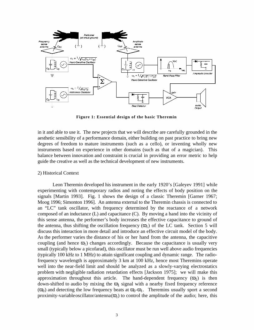
Figure 1: Essential design of the basic Theremin
in it and able to use it. The new projects that we will describe are carefully grounded in theaesthetic sensibility of a performance domain, either building on past practice to bring newdegrees of freedom to mature instruments (such as a cello), or inventing wholly newinstruments based on experience in other domains (such as that of a magician). Thisbalance between innovation and constraint is crucial in providing an error metric to helpguide the creative as well as the technical development of new instruments.
2) Historical Context
Leon Theremin developed his instrument in the early 1920’s [Galeyev 1991] whileexperimenting with contemporary radios and noting the effects of body position on thesignals [Martin 1993]. Fig. 1 shows the design of a classic Theremin [Garner 1967;Moog 1996; Simonton 1996]. An antenna external to the Theremin chassis is connected toan “LC” tank oscillator, with frequency determined by the reactance of a networkcomposed of an inductance (L) and capacitance (C). By moving a hand into the vicinity ofthis sense antenna, the performer’s body increases the effective capacitance to ground ofthe antenna, thus shifting the oscillation frequency (ω1) of the LC tank. Section 5 willdiscuss this interaction in more detail and introduce an effective circuit model of the body.As the performer varies the distance of his or her hand from the antenna, the capacitivecoupling (and hence ω1) changes accordingly. Because the capacitance is usually verysmall (typically below a picofarad), this oscillator must be run well above audio frequencies(typically 100 kHz to 1 MHz) to attain significant coupling and dynamic range. The radio-frequency wavelength is approximately 3 km at 100 kHz, hence most Theremins operatewell into the near-field limit and should be analyzed as a slowly-varying electrostaticsproblem with negligible radiation retardation effects [Jackson 1975]; we will make thisapproximation throughout this article. The hand-dependent frequency (ω1) is thendown-shifted to audio by mixing the ω1 signal with a nearby fixed frequency reference(ω0) and detecting the low frequency beats at ω0-ω1. Theremins usually sport a secondproximity-variable oscillator/antenna (ω2) to control the amplitude of the audio; here, this
3

ω2 signal is applied to a steep bandpass filter, then the amplitude of its output is detected todetermine the gain of a voltage controlled amplifier (VCA) in the audio path. As a handmoves near this volume-control antenna, ω2 moves into tune with the bandpass filter,changing the audio level through the VCA. Leon Theremin applied this idea in severalother inventions, such as the polyphonic Theremin, the Terpsitone (which responded to thebody gestures of dancers) and, anticipating the theme of our work described in thefollowing section, an electronic cello [Mattis and Moog 1992].
This general approach of comparing a variable oscillator (whose time constant is setby capacitive coupling to external objects) to a fixed reference frequency is employed inseveral common proximity-sensing applications, such as “stud finders,” which measure thelocal material density inside walls to determine the location of hidden support structures[Franklin 1978]. Such methods of electric field sensing we class as “loading mode”; i.e.,measuring the displacement current pulled from a transmitting electrode. Recentproximity-sensing applications [Vranish 1994] have dispensed with the dual-oscillatorTheremin structure, and use feedback amplifiers to directly measure the displacementcurrent (as discussed later; see Figure 15).
Although different applications of capacitive sensing have occasionally appeared invarious special performances over the last decades [e.g., Shapiro and Patterson 1972],most incarnations of capacitive measurement for musical applications since the Thereminhave been in touch-sensitive keyboards. One of the most refined examples is in thekeyboards designed by Moog and collaborators [Moog and Rhea 1990], which used theloading of the fingertips on an array of electrodes at each key to track finger positions afterkeys were hit. Simpler commercial examples are the touch keyboards packaged with theportable Synthi-AKS analog synthesizer from Electronic Music Systems (EMS) [Vail1993] and the synthesizers manufactured by Electric Dream Plant (EDP), namely the Waspand Gnat [Newcomb, 1994]; these trigger notes when a player contacts an insulated plate ateach key. Similar capacitive touch sensors were also used with the early Buchla analogsynthesizers and musical interfaces [Aikin 1984]. Most touch-keyboard designs sense thecapacitive coupling of ambient line frequency through the body, or use the added capacitiveloading of a finger on a plate to shift the phase of a clock signal [Lancaster 1988].
The Mathews/Boie radio drum [Mathews 1990] (Fig. 2) also employs a near-fieldcapacitive measurement. Unlike the single-electrode loading-mode designs outlined above,the radio drum determines the capacitance between an active baton (transmitter) and a set ofshaped “receive electrodes” in a plane below the baton. The signal broadcast by the batonis synchronously detected at the receivers in order to filter out background noise (suitablecircuitry is described in Section 3). A pair of batons can be used, which broadcast and aresynchronously detected at different frequencies so that they can be separately tracked. Asthe performer moves the baton in the sensitive region, the detected signals will vary as afunction of the distance (hence capacitive coupling) between the baton and the receiveelectrodes. By appropriately tapering the receive electrodes and processing the receivedsignals, the 3-D position of the baton can be determined and used to control a synthesizeror conduct a sequenced performance [Mathews 1989].
4

Figure 2: Proximity sensing in the Mathews/Boie Radio Drum
3) Tracking Cello Bows
Together with Joseph Chung, we developed the “hypercello” for Yo-Yo Ma’sperformance of Tod Machover’s composition Begin Again Again... [Machover 1991a].The hypercello sensors measured the player’s inputs to the instrument and used them tocontrol a range of sound sources. The goal of the sensing was to unobtrusively andresponsively detect the player’s actions as he followed notated music. A real-timecomputing environment mapped the sensor information into sounds, thereby extendingclassical technique so that gestures controlled notes, phrases, and algorithm parameters.
The cello, a RAAD built in Toronto, Canada by Richard Armin, used PVDFpiezoelectric polymer pickups [Duperray 1984] to sense the vibrations of the top plate,which was acoustically floating from a solid body so that little direct sound was radiated.In addition, when pressed, each string contacted a resistive thermoplastic strip (M-411from Mitech in Twinsburh, Ohio, USA) on the fretboard that sensed the positions of thefingers. The bow-wrist angle was measured using a Exos Wrist Master exoskeleton basedon magnets and Hall-effect sensors (Exos Inc., Burlington, Massachusetts, USA), and thebow position and pressure were determined by the system that is discussed below. Moreinformation on the other sensors mentioned above was presented in Gershenfeld [1991].A network of Macintosh computers gathered data from the sensors, processed these data inthe Hyperlisp environment [Chung 1988], and controlled samplers, synthesizers, andsignal processors to generate the output sounds. A block diagram of the system is shownin Figure 3.
5

Figure 3: Hypercello system for performance of Begin Again Again . . .
The most challenging sensing task was measuring the bow position (lateraldistance, δx) and placement (longitudinal distance from the bridge, δy). Previous studieshave either relied on signal processing to recognize bowed gesture from the audio stream[Nègyesy and Ray 1989; Hong 1992], or employed inertial sensors that have problemswith drift and optical techniques that have difficulty maintaining line-of-sight [Chafe 1995].The radio drum does not require contact between the baton and the planar receiver, butthere is not room on the bow or cello for such a large shaped electrode.
6

Figure 4: Block diagram of the cello bow position sensing system
We solved these problems by merging the techniques for measuring eachcoordinate, as shown in Figure 4. Capacitive coupling into a bow electrode measuredplacement, and making the bow electrode out of a resistive material added a real impedancethat varied with position [Gershenfeld 1993]. This geometry gave a useful signal over thefull bowing range that was linear and insensitive to bow rotations.
A sine wave of approximately 100 kHz frequency and 20V peak-to-peak amplitudewas transmitted from an antenna roughly 5 cm tall mounted behind the bridge, and thestrings were grounded to prevent perturbations from the player. The capacitance betweenthis antenna and the bow electrode was generally in the femtofarad (fF) range. The bowelectrode was made from a resistive thermoplastic (as above, M-411, having a resistivity of
7

Cpr
iL
iR
Resistive Strip(measure bow position)
Deformable Capacitor(measure bow pressure)
Shielded Cables(to analog conditioning)
Figure 5: Cello bow equipped with position sensors
Figure 6: Single channel of synchronously detecting receive electronics
1011 Ω-cm), cut into a 5 mm wide strip to give a resistance of a few MΩ and attached to thebow with a laminating tape2. Contact to this strip was made at either end by copper tapewith an electrically conducting glue3 and the signals were brought out by fine (47-mildiameter) flexible coaxial cable4 to maintain electrostatic shielding (Figure 5).
The small (circa 1 µA) displacement currents flowing from each end of the resistivestrip need to be separated from potentially much larger background noise (a performancestage can be a hostile electromagnetic environment, with background contributions fromlighting circuits, etc.); thus synchronous detection was used. As shown in Figure 6, theshielded coaxial cables were connected to the inputs of conventional JFET-input operationalamplifiers (such as the AD712 or TL082) configured as current-to-voltage converters(transimpedance amplifiers). These signals are then 4-quadrant multiplied by thetransmitted sine wave, which is phase-shifted to correct for the effects of cable capacitance(and the 90° lead from the capacitive displacement current, which can also be eliminated byusing an integrating capacitor in parallel with a bias return resistor for the amplifier
2 Tape 9449, 3M, St. Paul, MN.3 Tape 1181, 3M, St. Paul, MN.4 AS 450-3650SR, Cooner, Chatsworth, CA.
8

feedback network), and then low-pass filtered by a first-order filter with a cut-off of a fewhundred Hz (determined by a trade-off between the needed response time and positionresolution). This has the effect of creating a narrow band-pass filter centered on theoscillator frequency, with a width determined by the time constant of the output filter (herewe set δf/f ≈ 1%). Viewed in the time domain, the only noise that passes is the smallcomponent with frequency and phase close to that of the transmit oscillator. This alsoallows the front-end amplifier to be run at its optimum frequency for low-noiseperformance. If the frequency is too low, the 1/jωC impedance being measured is verylarge (hence the received current is small) and contributions from 1/f amplifier noiseincrease, reducing the signal-to-noise ratio. On the other hand, if the frequency is too high,the received amplitude again decreases due to finite front-end amplifier bandwidth, andeffects from parasitic cable capacitance become significant. Using the components listed,these considerations dictate an optimal frequency ranging 50-100 kHz. This sensitivecircuit, similar to the matched filter in a superheterodyne radio receiver, is simple andinexpensive (below $10 per channel). It can be made even less costly by using a CMOSswitch instead of the multiplier, but, unless a bandlimited front-end is used, this can add asmall amount of noise that is passed on the harmonics of the switching square wave.
These outputs from the two channels (left- and right-bow) were sampled as 12-bitintegers at 100 Hz and analyzed to determine the bow coordinates. The effective circuit isan AC-coupled potentiometer (Figure 7). In terms of these components, the currents ateach end (measured by the synchronous amplifiers) are:
i VR
R R R R j Ci V
R
R R R R CLR
L R L R aR
L
L R L R a=
+ +=
+ +0 0( ) / ( ) ( ) / (j )ω ω (1)
where RL and RR are the resistances along the strip from the bridge position to the left andright bow ends, Ca is the capacitance between the resistive strip and antenna, V0 is thetransmitter antenna drive voltage, and ω is the transmit frequency. The normalized currentdifference:
iL – iRiL + iR
=RR – RLRR + RL
=R0 + αx – R0 – αxR0 + αx + R0 – αx
= α xR0
(2)
is then independent of the capacitance, and since the resistances are proportional to thelateral displacement x (RL=R0 + αx and RR = R0 - αx, where α is the strip resistance per unitlength, R0 is half the strip resistance, and x=0 at mid-bow), this difference provides anestimate of x. The capacitance Ca falls off as 1/y (y is the distance from the bridge) forsmall y, because the two electrodes can be approximated as a parallel plate capacitor. Itthen crosses over to a 1/y2 decay at longer distances as the finite size of the electrodesbecomes significant and the electrodes can be approximated as a pair of point charges. Anumerical calculation of this falloff in Ca with y is shown in Figure 8. Since the capacitiveimpedance (>
~ 107 Ω) is much greater than the real impedance (<~ 106 Ω), and parallel-plate
coupling dominates over most of the bowing range, the inverse of the total current:
1iR + iL
= 1V0
RL RRRL +R R
+ 1jωCa
≈ 1jωCaV0
∝y
jωV0forsmall y (3)
9

Figure 7: Potentiometer analogy (left) and equivalent circuit (right) for bow receivers
Distance from Bridge [y] (cm)
Figure 8: Dependence of net capacitance (Ca) on antenna/bow separation
is approximately proportional to the distance of the bow from the bridge (y) . Therefore,from the sums and differences of the currents from the ends of the bow we can find theposition and placement of the bow.
Fig. 9 plots actual data taken from the bow. The top row shows the normalizedcurrent difference (Equation 2), and the bottom row shows the inverse sum (Equation 3).In both cases, the vertical coordinates were normalized to the range of bow motion in x andy. The left column shows data for transverse (x) bow strokes at constant y, and the rightcolumn shows data for longitudinal (y) bow motion towards and away from the bridgewith the bow kept centered at x=0. The decoupling of x and y predicted by Equations 2and 3 is seen in these plots; any residual deviation is dominated by the orthogonal motionof the bow during the measurements. Over a 50-cm bow stroke, it is possible to resolve a
10

0 10 200 5 10 15Pickup Signals; Difference over Sum (Equation 2)
0 5 10 15sec
Pickup Signals; Inverse Sum (Equation 3)
0 cm
0 cm
10 cm
20 cm
0 10 20sec
-25 cm
25 cm
δyδx
Lateral Bow Motion Longitudinal Bow Motion
Figure 9: Data from axial and transverse cello bow strokes
1-mm displacement. With sufficient care, such a system can even be extended to measuremicron displacements over centimeter ranges [Paradiso and Marlow 1994]. Because of thelack of symmetry in the antenna geometry, it is not possible to exactly solve for Ca (i.e., y)analytically; therefore, in practice, polynomials were fit to experimental measurements toconvert the currents into positions. These fits were very close to linear, as predicted byEquations 2 and 3.
The other important degree of freedom in bowing is the pressure. In order to avoidinterfering with the bow by measuring this directly from strain in the mounting of the bowhair [Askenfelt 1986], the force applied to the bow was measured under the player’sfingers where it is applied. Since there are no thin compression force sensors availablecommercially with the required sensitivity and response time, an elastic capacitor wasdeveloped using a thin (35 mil) urethane “Poron” foam5 with a modulus (9 PSI per 20%deflection) matched to finger forces. This capacitance was measured with the same circuitused for determining bow position (Figure 6).
5 4701-59-25035-1648, Poron, Rogers, CT.
11

Figure 10: Yo-Yo Ma performing in concert on the Hypercello
The hypercello has been used in over a dozen concert performances of Begin AgainAgain...; Figure 10 shows Yo-Yo Ma playing the system at the Tanglewood debut onAugust 14, 1991. This setup was also adapted to track a viola bow, played by the violistKim Kashkashian for the premiere of Machover’s Song of Penance with the Los\ AngelesPhilharmonic Contemporary Ensemble [Machover 1991b] .
4) Tracking Violin Bows
The cello bow position sensor described in the last section requires cablesconnected to the bow. These can be brought out without interfering with a cellist, who isalways seated, but this is not true for a violinist, who must perform standing up. Acompletely wireless bow was thus needed for a collaboration with Ani Kevaffian and theSt. Paul Chamber Orchestra in a performance of Machover’s hyperviolin compositionForever and Ever [Machover 1993]. The first attempted modification of the cello bow wasto place both a transmit and receive electrode on the violin to sense the perturbation of thefield by a passive resistive strip on the bow. This failed because the measurement wasdominated by the position of the player’s hand (although this accident proved to be veryuseful for other applications, as will be discussed in the next section). The successfulalternative that was developed for the violin bow involved reversing the roles of thecomponents; i.e. transmitting out from the bow and receiving at the violin bridge, as shownin Figure 11.
12

Figure 11: Block diagram of the wireless bow position sensor
Two low-power oscillators using CMOS 555 timer integrated circuits wereconnected to each end of the resistive strip and tuned to two different frequencies (50 kHzand 100 kHz). The associated circuitry was potted with the chips to make a small, stable,lightweight package that was attached to both ends of the bow. Here, the resistive stripacted as a voltage divider; the proportion of the two frequencies coupled into the bridgeantenna varies with the transverse bow position (x). An insulated electrode at the commonoscillator ground was placed near the bow frog, where it capacitively couples into the
13

0 2 4 6 8 10-20
-10
0
10
sec
0
200
400
600
Bow Placement (y)
Bow Position (x)
Bow Finger Pressure
Figure 12: Coordinates and pressure measured by the violin bow sensors
performer’s hand to define the system’s ground; the performer is also coupled to thereceiver ground through a metal foil on the violin that rests against her neck (this kind ofcoupling can also be exploited for intra-body signaling [Zimmerman 1995]).
The analog signal processing differs considerably from that developed for the cello.An FET source-follower is mounted on the violin, near the bridge antenna. This buffersthe received voltage, and drives a 5-meter shielded cable back to the conditioningelectronics. Because there is no direct connection between the bow and the conditioningelectronics, synchronous detection cannot be used without carrier recovery. Instead, thefront-end amplifier is followed by simple second-order bandpass filters; a Q of roughly 6provided adequate noise rejection for the performance needs. The outputs of the filterswere connected to the inputs of envelope followers, which produced voltagescorresponding to the amount of signal detected at the frequencies broadcast from theoscillators at each end of the bow. These voltages (vL, vR) were then processed to yieldestimates of the bow position (x,y), just as described for the cello with (iL, iR) inEquations 2 and 3.
To measure the bow pressure, a third CMOS oscillator, running at a differentfrequency (25 kHz in this case), drove a second antenna running the full length of the bow.The frequency of this oscillator was made to drop with applied pressure. This signal wasseparated in the receiver from those of the other two oscillators with a fourth-order resonantlow-pass filter, then a phased-locked-loop tracked the approximately 3 kHz change infrequency as the bow pressure was varied. Initial implementations used an elasticcapacitor, as developed for the cello, in the oscillator timing loop. This solution was notreliable in this circuit, however, as the sensor capacitance (and its change with pressure)
14

( )
30 - 100 kHzOscillator
∆φPhase Shifter
SynchronousDetector
V0To A/D
Converter
V1 ∝ ir1
TransimpedanceAmplifier
ir1
Transmit Receive
Performer
E
Figure 13: Layout of a single gesture sensor channel
was small, causing drift and mode-locking problems in the oscillator. Instead, a flat,piezoresistive strip from Interlink Electronics (Camarillo, California, USA) was trimmed tofit on the bow and mounted at the location where the index finger is placed. Thepiezoresistor was used in a simple resistive divider to create a low-impedance voltage thatvaried with applied pressure and was used to control the oscillator frequency. Althoughcomposite piezoresistors have significantly lower resolution than capacitive sensors, thissystem produced adequate response, as noted in Figure 12, which shows the reconstructedbow coordinates (per Equations 2 and 3) and measurement of applied finger pressure for aviolinist using this bow to execute a slow-to-fast dètachè. The applied pressure is seen tocycle with each bow stroke and generally increase at the conclusion of the phrase, as theplayer’s grip tightens while the phrase accelerates and the bowing excursion diminishes.
The three CMOS oscillators are powered from a small six-volt lithium camerabattery, mounted on the bow behind the frog. Because all oscillators together draw undertwo milliamperes of total current, the battery provides approximately 80 hours of constantoperation. This system, while usable, does modify the playing characteristics of the bow,mainly due to the added mass of the battery. To reduce this impact, we are currentlyresearching designs using extremely light, remotely powered, passive position sensors.
5) Tracking Body Gesture: Background
Figure 13 shows the geometry that we implemented when attempting to remotelydetect a resistive strip on a violin bow, as described earlier. We had hoped that thedynamic presence of the real impedance from the bowed strip would measurably perturbthe static complex impedances between electrodes. Instead, the signal was extremelysensitive to the position of the player’s hand, and had little to do with the bow. Further,
15

the sign of the effect was opposite from what would be naively expected. Bringing adielectric into the field increases the measured displacement current, because more charge isneeded on the plates to polarize the dielectric for a given voltage. Similarly, bringing aconductor into the field increases the displacement current, because it effectively brings theplates closer together. The hand is a conducting dielectric, yet inserting the hand into thefield has the opposite effect: the displacement current goes down. Experimenting withhamburger in a glove (to make a hand with a detachable arm [Zimmerman 1995]) quicklyreveals the explanation: the body is inhomogeneously in the field, and the AC coupling intothe room ground is strong enough for it to be able to screen the receiver.
Figure 14 shows this in more detail. Before the body comes into the field, there arefield lines going from the transmitter to the receiver. The associated capacitance C0 rangesfrom femto- to picofarads (fF to pF) for cm-scale electrodes. Once part of the body is inthe field, some field lines go into the body (Ct), some go from the body to the receiver(Cr), and some go from the body out to everything in the environment that is effectivelygrounded (Cg). In addition, free and bound charge in the body leads to frequency-dependent real and complex internal impedances.
The crucial point to appreciate is the relative magnitude of these effects. Ct and Crare typically comparable to C0, again ranging from fF to pF. Cg, on the other hand, ismuch larger, typically many pF. This includes field lines from the body going out to anypathway coupled to the environment’s ground; this can include cables, monitor cases,reinforcing beams, and furniture. Since the resistivity of the vascular system and moistbody tissue is low (a few hundred ohms), the body can be considered internally to be aperfect conductor on these scales (although we are studying applications of the smalldeviations from this good approximation). The potential of the body, then, is given by thecurrent flowing through it, dropped across the impedance of the ground return.
If Cg is much larger than Ct and Cr, the body becomes effectively grounded, and itscreens the field. It is then a good approximation to take the reduction in current measuredat the receiver to be the electric field strength integrated over the cross-sectional area of thebody, weighted by the strength of the ground return (we call this “shunt” mode). Thisobservation has many implications. One transmit/receive pair measures distance, since thefield strength (hence signal) falls off as a dipole (1/r3) normal to the electrodes; this givesus a single proximity-sensing channel. However, a pair of electrodes can’t distinguishbetween a large mass far away and a small mass nearby, or recognize a change in theground return strength. Two receivers with differing length scales break this degeneracy,or for a mass of fixed size, give the 2-D position, allowing a free hand to be used as ajoystick or computer mouse. Adding a third electrode distinguishes between rotations andtranslations in a 2-D measurement, or gives the 3-D position for a fixed-size mass, enablingthe hand to be used as a 3-D pointing device [Smith 1996]. In general, for any collectionof electrodes there is an ambiguity class of object distributions which cannot bedistinguished; enough electrodes must be used to determine the desired number ofindependent degrees of freedom, opening up a continuum from 1-D sliders to 3-D imaging.In order to explore these possibilities, we have constructed a programmable electrode array,which can dynamically transmit and receive from 16 different locations. This device isnow being used to research 3-D tomographic reconstruction of objects in the sensor fields[Smith 1995].
16

Figure 14: Equivalent circuit and modes of operation for electric field sensing
The length scale over which shunt mode can be used is set by the longest distancebetween transmitter and receiver (although with sufficient averaging, it is possible to makemeasurements at a few times this distance). Since the transmitter is a fixed voltage source,and the receiver is a virtual ground (up to deviations from ideal behavior in the op-amp andcable), a ground plane can be placed under the transmitter and receiver without influencingthe measurement, provided that transmit and receive electrodes are sufficiently closetogether (otherwise the ground plane shunts away significant transmit flux, attenuating thereceived signal). This technique allows the electrodes to be shielded in one direction. Forexample, a set of electrodes can be used on a grounded surface or tabletop, sensing abovebut not below. As with the bow electronics, each channel can be made for a few dollars inparts, and can remotely measure millimeter displacements of a person on millisecond timescales. Unlike familiar alternatives for finding people (as outlined in the introduction, e.g.,ultrasound, video, infrared), this fast and inexpensive measurement is independent of thefamiliar artifacts from surface texture, orientation, illumination, or ambient environment.Note that these voltages and frequencies are orders of magnitude from any health orregulatory concerns; their effect is comparable to running headphone cables near the body.
There is an important distinction between this shunt mode and the loading modeused in a Theremin. With shunt mode, known boundary conditions are set by thetransmit/receive geometry. The distance between the electrodes, and hence the length scaleof the field, is known and can be varied by using multiple transmitters or receivers. A set of
17

Figure 15: A transceiver electrode
N electrodes thus provide N(N-1)/2 independent shunt measurements. In loading mode,the unperturbed field lines go to unknown boundary conditions in the room, and Nelectrodes can be used only for N independent measurements. In this sense, an array ofelectrodes used for loading mode is like a focal-plane array without optics; an array used inshunt mode can be used for imaging [Smith 1995].
A simple modification of the receiver amplifier (Figure 15) permits it to operate as areceiver or as a transmitter (for loading or shunting mode). If Vref is at ground (switchopen in Fig. 15), this circuit is identical to the receiver circuit in Figure 6, except that thereare now two gain stages instead of one, which improves bandwidth and stability, whilereducing receiver sensitivity to the electrode cable length. On the other hand, if Vref isdriven by an oscillator (switch closed) and the feedback impedance dominates the shuntimpedance of the sensor cable, the op-amp will keep the transceiver electrode at theoscillator potential, turning the electrode into a transmitter. The differential amplifier,driven by low output-impedance sources, will then measure the current dropped across thisfeedback resistor, which is proportional to the capacitance loading the electrode, asdemonstrated by Vranish [1994]. In loading mode, this is the desired signal from thesingle-electrode measurement; in shunt mode, the transmitter’s signal is measured at areceiver.
At 100 kHz, the circuit of Figure 15 can work as a transmitter or shunt-modereceiver with an electrode connected across several meters of shielded input cable.Although the loading-mode measurement degrades much more quickly with cable length,some sensitivity can be recovered by using an activly driven shield (i.e., connect the inputcable’s shield to Vref instead of ground). Since this simple circuit becomes very smallwhen fabricated with surface-mount components, such transceiver front-ends can easily beembedded onto the electrodes themselves, entirely removing the input cable and itsassociated parasitic effects, while providing a low-impedance output that can drive muchlonger cables back to the demodulation electronics.
If the body is very close to the transmitter so that Ct is much larger than Cg, thebody becomes a virtual extension of the transmitter instead of a virtual ground. In this case(“transmit mode”), the signal radiated by the body falls off as a parallel-plate capacitor (1/r)
18
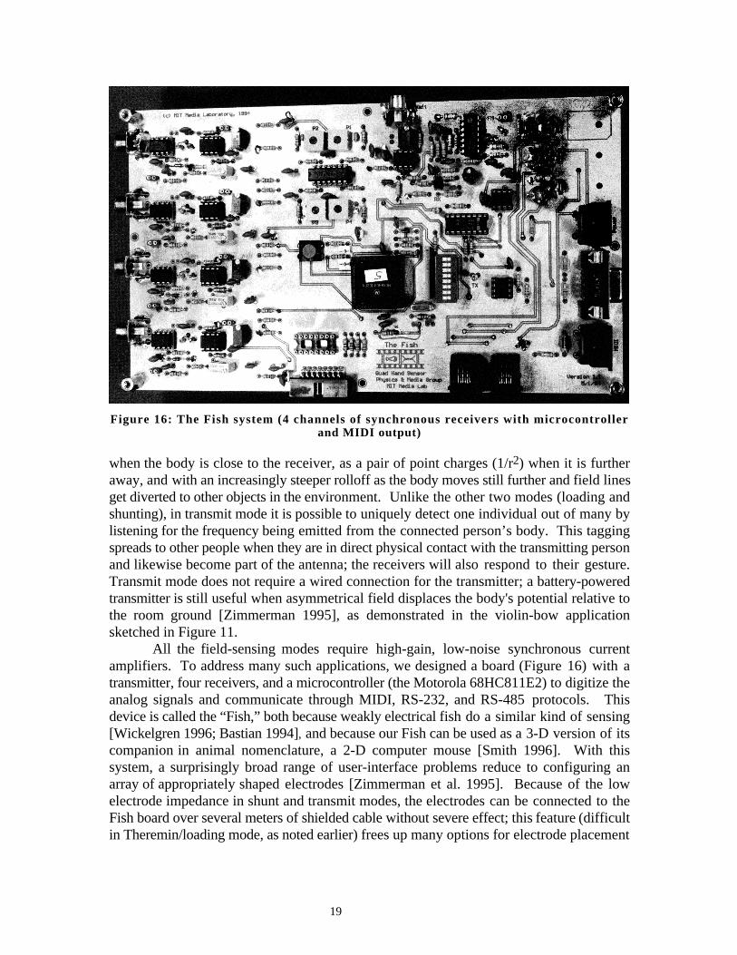
Figure 16: The Fish system (4 channels of synchronous receivers with microcontrollerand MIDI output)
when the body is close to the receiver, as a pair of point charges (1/r2) when it is furtheraway, and with an increasingly steeper rolloff as the body moves still further and field linesget diverted to other objects in the environment. Unlike the other two modes (loading andshunting), in transmit mode it is possible to uniquely detect one individual out of many bylistening for the frequency being emitted from the connected person’s body. This taggingspreads to other people when they are in direct physical contact with the transmitting personand likewise become part of the antenna; the receivers will also respond to their gesture.Transmit mode does not require a wired connection for the transmitter; a battery-poweredtransmitter is still useful when asymmetrical field displaces the body's potential relative tothe room ground [Zimmerman 1995], as demonstrated in the violin-bow applicationsketched in Figure 11.
All the field-sensing modes require high-gain, low-noise synchronous currentamplifiers. To address many such applications, we designed a board (Figure 16) with atransmitter, four receivers, and a microcontroller (the Motorola 68HC811E2) to digitize theanalog signals and communicate through MIDI, RS-232, and RS-485 protocols. Thisdevice is called the “Fish,” both because weakly electrical fish do a similar kind of sensing[Wickelgren 1996; Bastian 1994], and because our Fish can be used as a 3-D version of itscompanion in animal nomenclature, a 2-D computer mouse [Smith 1996]. With thissystem, a surprisingly broad range of user-interface problems reduce to configuring anarray of appropriately shaped electrodes [Zimmerman et al. 1995]. Because of the lowelectrode impedance in shunt and transmit modes, the electrodes can be connected to theFish board over several meters of shielded cable without severe effect; this feature (difficultin Theremin/loading mode, as noted earlier) frees up many options for electrode placement
19
T
T
R R
R R
a) Dual shunt-axis frame b) Sensor Mannequin
R
T
R
R R
R
T
R(at back)
FishUnit
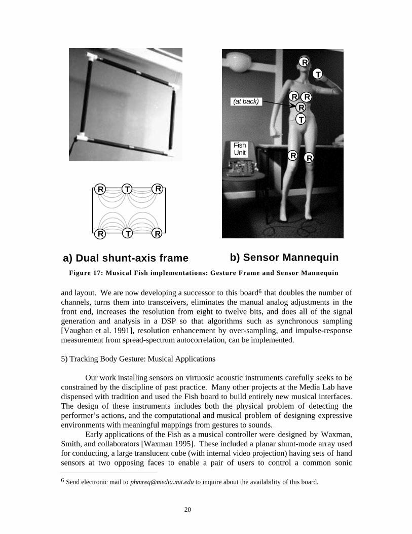
Figure 17: Musical Fish implementations: Gesture Frame and Sensor Mannequin
and layout. We are now developing a successor to this board6 that doubles the number ofchannels, turns them into transceivers, eliminates the manual analog adjustments in thefront end, increases the resolution from eight to twelve bits, and does all of the signalgeneration and analysis in a DSP so that algorithms such as synchronous sampling[Vaughan et al. 1991], resolution enhancement by over-sampling, and impulse-responsemeasurement from spread-spectrum autocorrelation, can be implemented.
5) Tracking Body Gesture: Musical Applications
Our work installing sensors on virtuosic acoustic instruments carefully seeks to beconstrained by the discipline of past practice. Many other projects at the Media Lab havedispensed with tradition and used the Fish board to build entirely new musical interfaces.The design of these instruments includes both the physical problem of detecting theperformer’s actions, and the computational and musical problem of designing expressiveenvironments with meaningful mappings from gestures to sounds.
Early applications of the Fish as a musical controller were designed by Waxman,Smith, and collaborators [Waxman 1995]. These included a planar shunt-mode array usedfor conducting, a large translucent cube (with internal video projection) having sets of handsensors at two opposing faces to enable a pair of users to control a common sonic
6 Send electronic mail to [email protected] to inquire about the availability of this board.
20

B
A
C
CD
D
E
A: Copper plate on chair top to transmit 70 kHz carrier signalB: Four illuminated antennas to sense hand positionsC: Two antennas to detect left and right feetD: Two pushbuttons for generating sensor-independent triggersE: Digital display for computer to cue performerF: Four lights under chair platform, nominally controlled by foot sensors
Legend:F
Figure 18: Layout of the “Spirit Chair”
environment, and a room that responded to the location of occupants by having atransmitter under the floor and receivers on the walls. To address the needs of severalmusic projects, we have designed a general planar structure for shunt-mode handmeasurement (the frame shown in Figure 17a) that has transmitters and receivers mountedon 75-cm-long PVC pipes as sketched in the bottom diagram. Duets have been written forpairs of such frames, where the players face one another across these “windows” andcollaboratively control algorithms that respond to collective motion [Waxman 1995].
Since the electrodes can sense through insulating materials, they can easily beembedded in other structures to provide a specific visual and/or tactile impression. Perhaps
21
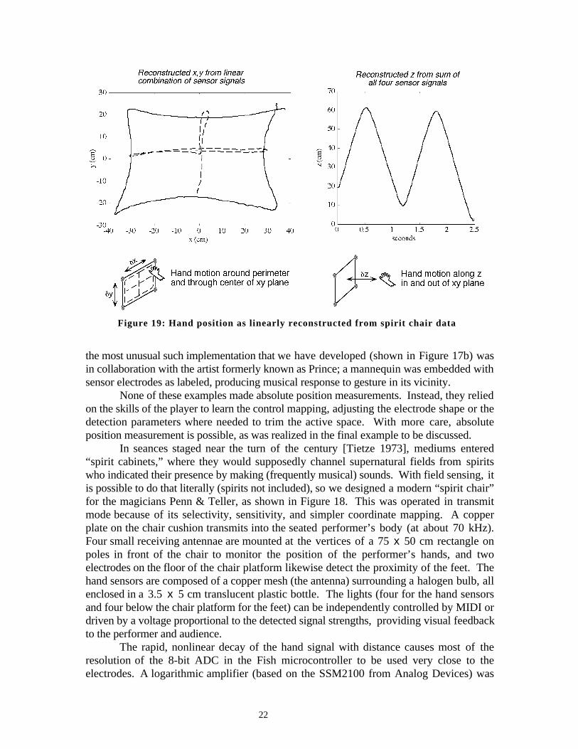
Figure 19: Hand position as linearly reconstructed from spirit chair data
the most unusual such implementation that we have developed (shown in Figure 17b) wasin collaboration with the artist formerly known as Prince; a mannequin was embedded withsensor electrodes as labeled, producing musical response to gesture in its vicinity.
None of these examples made absolute position measurements. Instead, they reliedon the skills of the player to learn the control mapping, adjusting the electrode shape or thedetection parameters where needed to trim the active space. With more care, absoluteposition measurement is possible, as was realized in the final example to be discussed.
In seances staged near the turn of the century [Tietze 1973], mediums entered“spirit cabinets,” where they would supposedly channel supernatural fields from spiritswho indicated their presence by making (frequently musical) sounds. With field sensing, itis possible to do that literally (spirits not included), so we designed a modern “spirit chair”for the magicians Penn & Teller, as shown in Figure 18. This was operated in transmitmode because of its selectivity, sensitivity, and simpler coordinate mapping. A copperplate on the chair cushion transmits into the seated performer’s body (at about 70 kHz).Four small receiving antennae are mounted at the vertices of a 75 x 50 cm rectangle onpoles in front of the chair to monitor the position of the performer’s hands, and twoelectrodes on the floor of the chair platform likewise detect the proximity of the feet. Thehand sensors are composed of a copper mesh (the antenna) surrounding a halogen bulb, allenclosed in a 3.5 x 5 cm translucent plastic bottle. The lights (four for the hand sensorsand four below the chair platform for the feet) can be independently controlled by MIDI ordriven by a voltage proportional to the detected signal strengths, providing visual feedbackto the performer and audience.
The rapid, nonlinear decay of the hand signal with distance causes most of theresolution of the 8-bit ADC in the Fish microcontroller to be used very close to theelectrodes. A logarithmic amplifier (based on the SSM2100 from Analog Devices) was
22

Figure 20: Block Diagram of the spirit chair performance system
therefore inserted between the demodulated hand-sensor receiver outputs and the A/Dconverter. This very nearly linearizes the signal, and extends the useful gesture range toabout three feet (beyond which the performer’s body interferes). Because an interpretedsoftware environment was used for this piece (Hyperlisp running on a Macintosh Quadra650), this hardware linearization was also valuable for reducing the computational burdenon the host in estimating the 3-D hand position from the four sensor readings.
Before a performance, readings were taken of the hand position in a 3 x 3 grid(cued by the lights), and a linear least-squares fit was generated to compensate slowchanges in the electrostatic environment and any gradual drift in the front-end electronics.Because Penn is so much larger than Teller (their weight ratio is roughly 1.5:1), separatefits were kept for each performer. This worked well: Figure 19 shows the reconstructedposition of a hand tracing a grid in real space. The small residual pincushion distortioncould be removed by a higher-order fit, but this was unnecessary for the gestural mappingsused in the performance. Figure 19 also shows the sum of all four signals for a handmoving in and out normal to the center of the rectangle of receivers; as can be readily noted,this gives a good linear estimate of the hand’s distance from the sensor plane.
Figure 20 shows a block diagram of the entire performance system [Paradiso1994]. The Fish board at its heart has been modified to accommodate six receivers, withlog amplifiers on the four hand sensor channels. The 68HC11 microcontroller also acceptsMIDI commands for the other interface devices, including eight lighting channelsassociated with the sensors, a pair of bright LED’s on the chair that can be used to indicatetempo, and a two-digit, chair-mounted display to provide performance cues. A pair offootswitches allows sensor-independent triggers, used for explicitly changing parameters inthe midst of performance, or instigating triggers when the performer is not seated andhence is unable to use the sensors.
23

Figure 21: Penn and Teller performing with the spirit chair
As shown in Figure 21, the spirit chair was used in Penn and Teller’s performance[Machover 1994a] of Machover’s Media Medium [Machover 1994b], a mini-opera thatintegrated the music and chair system into a seance escape trick [Tietze 1973]. Theportions of this composition that used the electric field sensors were written as a sequentialseries of modes with different (and in some cases dynamic) mappings of sonic events andeffects onto hand position and motion. Some modes in the piece used the proximity of theperformer’s hand to the plane of the sensors (z) to launch a sound and adjust its volume,and the position of the hand in the sensor plane (x,y) to change the timbral characteristics.Other modes divided the x,y plane into many zones, which contained sounds andsequences triggered when the hand moved across their boundary. One such modeincorporated 400 percussion sounds distributed evenly across the sensor plane, plus a pairof kick drums on the foot pedals. These triggers were temporally quantized, allowing evenan amateur to perform a tight drum solo by waving one’s hands and tapping one’s feet.Another mode enabled telerobotic control of a Yamaha Disklavier piano; the player couldtrigger notes by moving a hand forward, with the intensity of the hit determined by thespeed of hand motion; foot position controlled the pedals.
As in the seance tricks of yesteryear, public audiences in touring performancesoften seemed skeptical that the sensor chair was really producing live sound under thecontrol of the performer. Unless one is actually sitting in the chair, it is easy to concludefrom observing the generation of sound without obvious connection that the performer isacting along with pre-sequenced music. This is a subtle and recurring problem as gesturalsound mappings become complex and the technology gets more “magical”; how importantis it for the audience (and even the performer) to understand the causal relationship betweenwhat is seen and what is heard?
Although the spirit chair was not intended to be a useful general-purpose computerinterface device, its geometry has been applied successfully to information navigation.Mounting the receiving electrodes around a computer monitor enables simple “flying” bodygestures to control motion through a virtual environment, producing a very intuitiveinterface that would be cumbersome with a conventional pointing device [Allport et al.1995].
24

6) Conclusions
We have surveyed the three primary modes of applying electric field sensing topeople and objects (loading, shunting, and transmitting) and examined their relativestrengths and weaknesses. Briefly, loading mode is convenient because it is asingle-electrode measurement; shunting mode falls off more quickly with distance, but isbetter suited to defining sensitive regions and making absolute 3-D measurements; transmitmode is best suited to simple point-tracking applications and can most easily distinguishamong multiple objects. Starting with the Theremin, and moving through enhanced stringinstruments to smart furniture, we have shown that the same relatively simple andinexpensive circuitry can be applied to old and new musical-interface applications thatunobtrusively detect a performer’s actions at their limiting temporal and spatial resolution.These data can then be mapped into sounds at levels of interaction ranging from simplepitch control to complex shaping of algorithms.
The basic ideas reported here are very old. Although people-sensing applicationsof capacitive sensing have been known for almost a century, nearly all have beenunderstood and pursued as loading-mode devices. Our experience building new musicalinterfaces and exploring the underlying physics has helped us to appreciate many differentelectrical transport mechanisms that were historically lumped together into a categorytermed capacitance measurement. Pulling these apart has led us to a broad range of newdevices, ranging from simple gesture sensors to new techniques for 3-D imaging.
Our hope is that the simplicity and flexibility of interface design with field sensorswill help both manufacturers and musicians take a more creative and demanding view ofhow people control musical instruments. An instrument should be expected to match thephysical capabilities of the player, so that the only limitation is the player’s intent ratherthan all-too-familiar hardware deficiencies.
7) Acknowledgments
This research would be impossible without the members of the Physics and MediaGroup and the thoughtful guidance that comes from our close creative collaboration withTod Machover and his students. We would also like to thank our tolerant artisticcollaborators, particularly Yo-Yo Ma, Penn & Teller, and Ani Kevaffian, and our technicalcolleagues, including David Allport, Joseph Chung, Rick Ciliberto, Barrett Comisky, EranEgozy, Ed Hammond, Andy Hong, Theresa Marrin, Pete Rice, Josh Smith, DavidWaxman, and Tom Zimmerman. We are grateful for support from the members of theMedia Lab's Things That Think Consortium, and for inspiration from Max Matthews, BobBoie, and Bob Moog.
25

8) References
Aikin, J., “Don Buchla,” The Art of Electronic Music, William Morrow and Co., NY,1984, pp. 75-83.
Allport, D., Rennison, E., Straussfeld, L., “Issues of Gestural Navigation in AbstractInformation Space,” CHI 95: Human Factors in Computing Systems, ACM Press,Denver, Co., 1995, pp. 206-207.
Anderton, C., “STEIM: In the Land of Alternate Controllers,” Keyboard, Vol. 20, No. 8,August 1994, pp. 54-62.
Askenfelt, A., “Measurement of Bow Motion and Force in Violin Playing,” J. AcousticSoc. Am. 80, 1986, 1007-1015.
Azevedo, S. and McEwan, T.E., “Micropower Impulse Radar,” Science and TechnologyReview, Lawrence Livermore National Laboratory, January/February 1996, pp. 16-29.
Bastian, J., “Electrosensory Organisms,” Physics Today, Vol. 47, No. 2, February 1994,pp. 30-37.
Chabot, X., “Gesture Interfaces and a Software Toolkit for Performance with Electronics,”Computer Music Journal, Vol. 14, No. 2, 1990, pp. 15-27.
Chafe, C., CCRMA, Stanford, CA, Personal Communication, April 1995.Chung, J., “Hyperlisp Reference Manual,” MIT Media Laboratory Technical Report,
Music and Cognition Group, 1988.Collinge, D.J. and Parkinson, S.M., “The Oculus Ranae,” ICMC Proceedings, 1988, pp.
15-19.Duperray, J.L., “Les Nouveaux Violons,” Diapason, No. 296, July-August 1984, pp.
88-89.Fisher, C.R. and Wilkinson, S., “DIY: Build the EM Optical Theremin,” Electronic
Musician, Vol. 11, No. 5, May 1995, pp. 58-64.Franklin, R. and Fuller, F., “Electronic Wall Stud Sensor,” US. Patent No. 4099118, July
4, 1978.Galeyev, B.M., “L.S. Termen: Faustus of the Twentieth Century,” Leonardo, 24(5):573-
579, 1991.Garner, L., “For that Different Sound, Music a’la Theremin,” Popular Electronics Vol. 27,
No. 5, November 1967, pp. 29-33,102-103.Gehlhaar, R., “SOUND=SPACE: an Interactive Musical Environment,” Contemporary
Music Review, Vol. 6, Part 1, 1991, pp. 59-72.Gershenfeld, N., “Sensors for Real-Time Cello Analysis and Interpretation,” Proc. of the
1991 ICMC, Montreal, Canada, 1991, p. 151.Gershenfeld, N., “Method and Apparatus for Electromagnetic Non-Contact Position
Measurement With Respect To One Or More Axes,” US Patent No. 5,247,261,Sept. 21, 1993.
Hong, A., “Non-linear Analysis of Cello Pitch and Timbre,” MS Thesis, MassachusettsInstitute of Technology, September 1992.
Jackson, J.D., Classical Electrodynamics, Wiley, New York, 1975.Lancaster, D., CMOS Cookbook; Second Edition, Sams; Prentice Hall Computer
Publishing, Carmel, Indiana, 1988, pp. 332-336.Machover, T., Begin Again Again..., musical score, Ricordi, Milan/Paris, 1991(a).Machover, T., Song of Penance, Ricordi, Milan/Paris, 1991(b).
26

Machover, T., “Hyperinstruments: A Progress Report,” available from the MediaLaboratory, Massachusetts Institute of Technology, Cambridge, MA., 1992.
Machover, T., Forever and Ever, musical score, Ricordi, Milan/Paris, 1993.Machover, T., Penn’s Sensor Solo and Teller’s Finale, performance at the Digital
Expression Symposium, MIT Kresge Auditorium, October 20, 1994 (a).Machover, T., Media Medium, musical score, Ricordi, Milan/Paris, 1994 (b).Mann, S., “DopplerDanse: Some Novel Applications of Radar,” Leonardo, Vol. 25, No.
1, 1992, p. 91.Martin, S., “The Electronic Odyssey of Leon Theremin,” Documentary film, OrionPictures, 1993.Mathews, M.V., “The Conductor Program and Mechanical Baton,” Current Directions in
Computer Music Research, MIT Press, Cambridge, MA., 1989, pp. 263-281.Mathews, M.V., “Three Dimensional Baton and Gesture Sensor,” US Patent No.
4980519, Dec. 25, 1990.Mattis, O. and Moog, R., “Leon Theremin; Pulling Music out of Thin Air,” Keyboard,
Vol. 18, No. 2, February 1992, pp. 46-54.McMillen, K., Wessel, D.L., Wright, M., “The ZIPI Music Parameter Description
Language,” Computer Music Journal, 14(4), 1994, pp. 52-73.Moog, R.A. and Rhea, T.L., “Evolution of the Keyboard Interface: The Bösendorfer 290
SE Recording Piano and the Moog Multiply-Touch-Sensitive Keyboards,” ComputerMusic Journal, 14(2), 1990, pp. 52-60.
Moog, R., “Theremin Virtuoso, Clara Rockmore, Recollections of Genius,” Keyboard,Vol. 20, No. 2, February 1994, pp. 58,69-70,184.
Moog, R., “Build the EM Theremin,” Electronic Musician, Vol. 12, No. 2, February1996, pp. 86-100.
Nègyesy, J. and Ray, L., “Zivatar: A Performance System,” in M.V. Mathews, J.R.Pierce ed. Current Directions in Computer Music Research, MIT Press, Cambridge,MA, 1989, pp. 283-289.
Newcomb, M.J., The Museum of Synthesizer Technology, PO Box 36, Ware, Herts, UK,July 1994, pp. 89-92.
Paradiso, J.A. and Marlow, D., “Electronics for the Precision Alignment of the GEMMuon System,” Proc. of the 1994 Electronics for Future Colliders Conference, LeCroyCorporation, Chestnut Ridge, NY, May 1994, pp. 235-249.
Paradiso, J.A., “Penn and Teller Seance Electronics,” Physics and Media Group Report,MIT Media Lab, Dec. 1994.
Puckette, M., “Combining Event and Signal Processing in the MAX ProgrammingEnvironment,” Computer Music Journal 15(3), pp. 68-77, 1991.
Rich, R., “Buchla Lightning MIDI Controller,” Electronic Musician, Vol. 7, No. 10,October 1991, pp. 102-108.
Roads, C., The Computer Music Tutorial, MIT Press, Cambridge, MA, 1996, pp.617-658.
Rockmore, C., The Art of the Theremin, CD on Delios International, Santa Monica, CA,1987.
Rubine, D. and McAvinney, P., “Programmable Finger-tracking Instrument Controllers,”Computer Music Journal, Vol. 14, No. 1, 1990, pp. 26-41.
27

Shapiro, G. and Patterson, W., “From the Yellow Castle,” research at Brown Universityand performances at the Automation House, New York City, April 1972.
Simonton, J., “Build This Theremin,” Electronics Now, Vol. 67, No. 2, February 1996,pp. 31-32,56-59.
Slater, M., “Universal Serial Bus to Simplify PC I/O,” Microprocessor Report, Vol. 9,No. 6, pp. 1,6-9, April 17, 1995. See also http://www.teleport.com/~USB/.
Smith, J.O., “Physical Modeling Using Digital Waveguides,” Computer Music Journal16(4), 1992, pp. 74-91.
Smith, J. R., “Toward Electric Field Tomography,” MS Thesis, Massachusetts Institute ofTechnology, Summer 1995.
Smith, J.R., “Field Mice: Extracting Hand Geometry from Electric Field Measurements,”to appear in IBM Systems Journal, 1996.
Tietze, T.R., Margery, Harper & Row, New York, 1973.Vail, M., “EMS VCS3 & Synthi A/AKS,” Vintage Synthesizers, Miller Freeman Books,
San Francisco, CA, 1993, pp. 102-106.Vaughan, R.G., Scott, N.L., White, D.R., “The Theory of Bandpass Sampling,”IEEE
Transactions on Signal Processing, Sept. 1991, 39 (9), pp.1973-84.Vranish, J.M., “Capaciflector Camera,” NASA Tech Briefs, 18(10), pp. 58-62, October
1994.Waxman, D., “Digital Theremins: Interactive Musical Experiences for Amateurs using
Electric Field Sensing,” MS Thesis, Massachusetts Institute of Technology, Summer1995.
Weigend, A. and Gershenfeld, N., ed. Time Series Prediction: Forecasting the Future andUnderstanding the Past, Santa Fe Institute Studies in the Sciences of Complexity,Addison-Wesley, Reading, MA, 1993.
Wickelgren, I., “The Strange Senses of Other Species,” IEEE Spectrum, Vol. 33, No. 3,March 1996, pp. 32-37.
Wren, C.R, Sparacino, F., et al., “Perceptive Spaces for Performance and Entertainment:Untethered Interaction using Computer Vision and Audition,” MIT Media LabPerceptual Computing Report TR#372, Submitted to Applied Artificial Intelligence(AAI) Journal, Special Issue on Entertainment and AI/ALife, March 1996.
Zimmerman, T.G., “Personal Area Networks (PAN): Near-Field IntrabodyCommunication,” Masters Thesis, MIT, June 1995.
Zimmerman, T.G., Smith, J.R., Paradiso, J.A., Allport, D., Gershenfeld, N., “ApplyingElectric Field Sensing to Human-Computer Interfaces,” CHI 95: Human Factors inComputing Systems, ACM Press, Denver, Co., 1995, pp. 280-287.
28