mwb6600-0197%3a+pro+series+37+wide+belt+sander+
DESCRIPTION
Dear Woodworker: Thank you again for becoming a Laguna Tools customer. Torben Helshoj President and Founder – Laguna Tools Imagination, Innovation and Invention at work. I started Laguna Tools as a woodworker; I still am.TRANSCRIPT


Dear Woodworker:
Thank you for your purchase and welcome to the Laguna Tools group of discriminating woodworkers. I understand that you have a choice of where to purchase your machines and appreciate the confidence you have in our products.
Every machine sold by Laguna Tools has been carefully designed and well thought through from a woodworker’s perspective. I cut on our bandsaws, lathes, table saws and combination machines. Through my hands-on experience, I work hard to make our machines better. I strive to give you machines that inspire you to create works of art. Machines that are a joy to run and work on. Machines that encourage your performance.
Today, we offer high-performance machines with innovative solutions that meet the needs of woodworkers and their ever-evolving craft.
I started Laguna Tools as a woodworker; I still am.
Thank you again for becoming a Laguna Tools customer.
Torben Helshoj
President and Founder – Laguna Tools
Imagination, Innovation and Invention at work.

3
Table of contents Page number Safety Rules 4 Warranty 5 Noise emission 6 Specification sheet 6 Receiving your wide belt sander 7 Introduction to your wide belt sander 8 What you will receive. 12 Parts of the wide belt sander 8 Where to locate your wide belt sander 12 Unpacking your wide belt sander 13 Assembly and setup 13 Adjusting the wide belt sander 18 Running the sander 24 Maintenance and troubleshooting 27 Electrical drawing 40 Exploded view drawings 41
4
Safety Rules. As with all machinery, there are certain hazards involved with the operation and use. Using it with caution will considerably lessen the possibility of personal injury. However, if normal safety precautions are overlooked or ignored, personal injury to the operator may result. If you have any questions relative to the installation and operation, do not use the equipment until you have contacted your supplying distributor. Read the following carefully before operating the machine.
1. Keep the working area clean and be sure adequate lighting is available.
2. Do not wear loose clothing, gloves, bracelets, necklaces or ornaments. Wear face, eye, respiratory and body protection devices as indicated for the operation or the environment.
3. Be sure that the power is disconnected from the machine before tools are serviced or an attachment is to be fitted or removed.
4. Never leave the machine with the power on. 5. Do not use dull, gummy or cracked cutting tools. 6. Be sure that the keys and adjusting wrenches have been
removed and all the nuts and bolts are secured.

5
LIMITED WARRANTY New woodworking machines sold by Laguna Tools carry a one-year warranty effective from the date of shipping. Laguna Tools guarantees all new machines sold to be free of manufacturer’s defective workmanship, parts and materials. We will repair or replace, without charge, any parts determined by Laguna Tools, Inc., to be a manufacturer’s defect. We require that the defective item/part be returned to Laguna Tools with the complaint. In the event the item/part is determined to be damaged due to lack of maintenance, cleaning or misuse/abuse, the customer will be responsible for the cost to replace the item/part, plus all related shipping charges. This limited warranty does not apply to natural disasters, acts of terrorism, normal wear and tear, product failure due to lack of maintenance or cleaning, damage caused by accident, neglect, lack of or inadequate dust collection, misuse/abuse or damage caused where repair or alterations have been made or attempted by others. Laguna Tools, Inc., is not responsible for additional tools or modifications sold or performed (other than from/by Laguna Tools, Inc.) on any Laguna Tools, Inc., woodworking machine. Warranty maybe voided upon the addition of such described tools and/or modifications, determined on a case-by-case basis. Normal user alignment, adjustment, tuning and machine settings are not covered by this warranty. It is the responsibility of the user to understand basic woodworking machinery settings and procedures and to properly maintain the equipment in accordance with the standards provided by the manufacturer. Parts, under warranty, are shipped at Laguna Tools, Inc.’s cost either by common carrier, FEDEX ground service or a similar method. Technical support to install replacement parts is primarily provided by phone, fax, e-mail or Laguna Tools Customer Support Website. The labor required to install replacement parts is the responsibility of the user. Laguna Tools is not responsible for damage or loss caused by a freight company or other circumstances not in our control. All claims for loss or damaged goods must be notified to Laguna Tools within twenty-four hours of delivery. Please contact our Customer Service Department for more information. Only new machines sold to the original owner are covered by this warranty. For warranty repair information, call 1-800-332-4094. Copyright 2010 Laguna Tools, Inc ** Warning – no portion of these materials may be reproduced without written approval from Laguna Tools, Inc.

6
SPECIFICATION Main motor 20HP Variable feed speed 1HP Table lifting motor 0.25HP Voltage 220V / three phase Max sanding height 5" (127 mm) Min sanding height 1/4" (6.4 mm) Max sanding width 36 1/2" (927 mm) Sanding belt size 37" x 75" (940 mm x 1905 mm) Diameter of sanding drum 4" (100 mm) Length of sanding drum 38" (965 mm) Sanding drum RPM 1725 RPM Conveyor speed 15-49 FPM Dust port size 4" (100 mm) Number of dust ports 3 Foot print 19" x 51" (483 mm x 1300 mm) Width x Depth 25 1/2" x 52" (650 mm X 1320 mm) Height with dust collection ports 77 1/2" (1968 mm) Height without dust collection ports 71 1/2" (1816 mm) Conveyor height at lowest setting 32" (813 mm) Cabinet Steel Operating air pressure 6 Bar Sanding belt oscillation Adjustable Sanding belt motor break Yes. Air operated disc break
Noise emission. Notes concerning noise emission. Given that there exists a relationship between noise level and exposure times, it is not precise enough to determine the need for supplementary precautions. The factors affecting the true level of exposure to operators are clearly the amount of time exposed, the characteristics of the working environment, such as other sources of dust and noise – for example, adjacent machines – in other words, the level of ambient noise. It is possible that exposure level limits will vary from country to country. Specification sheet for wide belt sander.
7
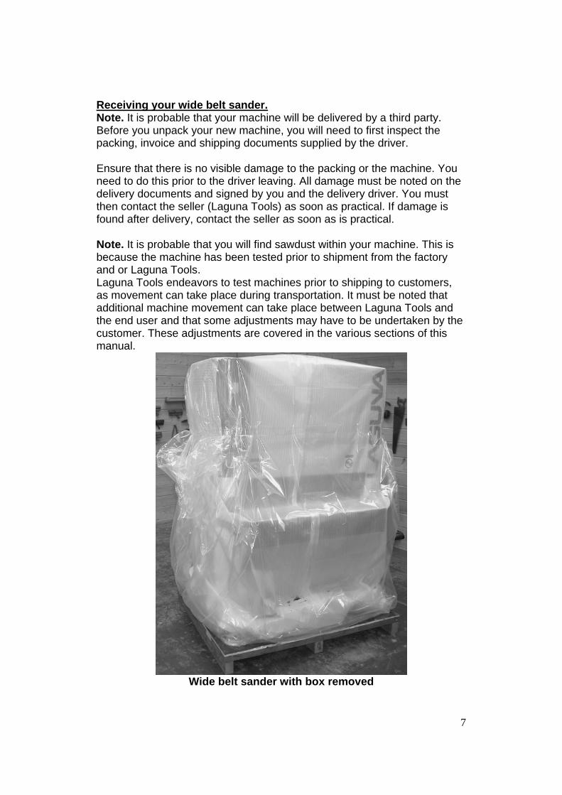
Receiving your wide belt sander. Note. It is probable that your machine will be delivered by a third party. Before you unpack your new machine, you will need to first inspect the packing, invoice and shipping documents supplied by the driver. Ensure that there is no visible damage to the packing or the machine. You need to do this prior to the driver leaving. All damage must be noted on the delivery documents and signed by you and the delivery driver. You must then contact the seller (Laguna Tools) as soon as practical. If damage is found after delivery, contact the seller as soon as is practical. Note. It is probable that you will find sawdust within your machine. This is because the machine has been tested prior to shipment from the factory and or Laguna Tools. Laguna Tools endeavors to test machines prior to shipping to customers, as movement can take place during transportation. It must be noted that additional machine movement can take place between Laguna Tools and the end user and that some adjustments may have to be undertaken by the customer. These adjustments are covered in the various sections of this manual.
Wide belt sander with box removed

8
Introduction to your wide belt sander. This machine is designed to give you years of safe service. Read this owner’s manual in its entirety before assembly or use. Parts of the wide belt sander. The wide belt sander consists of a number of major parts, which are discussed in this manual. Take the time to read this section and become familiar with the machine. Identification. There is a plate on the side of the machine listing all the manufacturing data, including the model.
1
2 3 4 5 6
7
8 9 10
1. Control panel. The control panel controls all the electrical functions of the machine. This includes the speed of the drive belt, vertical adjustment of the bed and on/off functions 2. Bed vertical setting device. This device is used to set the height of the bed in relation to the sanding rollers.

9
3. Manual bed vertical adjusting handle. This handle is used to manually adjust the bed vertically. 4. Bed. The bed of the sander has a rubber drive belt that transports the job through the machine. The speed of the belt is adjustable. 5. Safety plate. The safety plate is used to remove power from the motors. This is very convenient should a job get jammed, as it can be operated by hand, leg or hip. 6. Machine body. The machine body is manufactured from heavy-gauge steel. 7. Dust extraction. There are three dust extraction pipes located on the top of the machine and are 4 inches (100mm) in diameter. Dust extraction is critical when sanding. The sander produces a lot of sawdust that must be removed for health reasons and also because the belt will clog and poor surface finish will result. It is not possible to be exact when recommending what size of dust collector should be used; this will depend on the type of work that the machine is used for. It is recommended that a dust collector with a minimum of 3500 cubic feet/minute is attached to the sander. 8. Belt drive. The belt speed is variable between 6-30FPM. The belt speed is adjusted by the control knob, which must only be adjusted while the belt is running. To decrease the speed, turn the adjuster clockwise. To increase the speed, turn the adjuster counter-clockwise. 9. Air supply. A clean dry air supply with a minimum pressure of 6 bar must be connected to the sander. If the pressure drops below 5 bar, the machine will stop functioning. 10 Electrical control box. The electrical control box houses all the electrical control components and must never be opened while power is supplied to the machine.

10
11
12
13 14
15
11. Sanding drum motor. 12. Bed vertical adjusting motor. The bed vertical adjusting motor moves a chain that rotates four cogs. The cogs turn threaded shafts that lift or lower the bed. 13. Sanding belt limiter. There are two ceramic limiters, one on either side of the machine. If the belt hits either of the limiters, a micro switch is activated and the machine will stop. If the sanding belt hits any of the limiters, the sanding belt will have to be adjusted prior to restarting the sander. 14. Sanding belt sensor. This sensor controls the action of the sanding belt oscillation. As the belt moves in and out of the sensor, a piston moves a cam that is attached to the top sanding roller. This action changes the angle of the top roller and forces the belt to move along the roller. 15. Sanding belt control knobs. These knobs control the actions of the sanding belt sensor and also the amount of oscillation of the sanding belt.
11
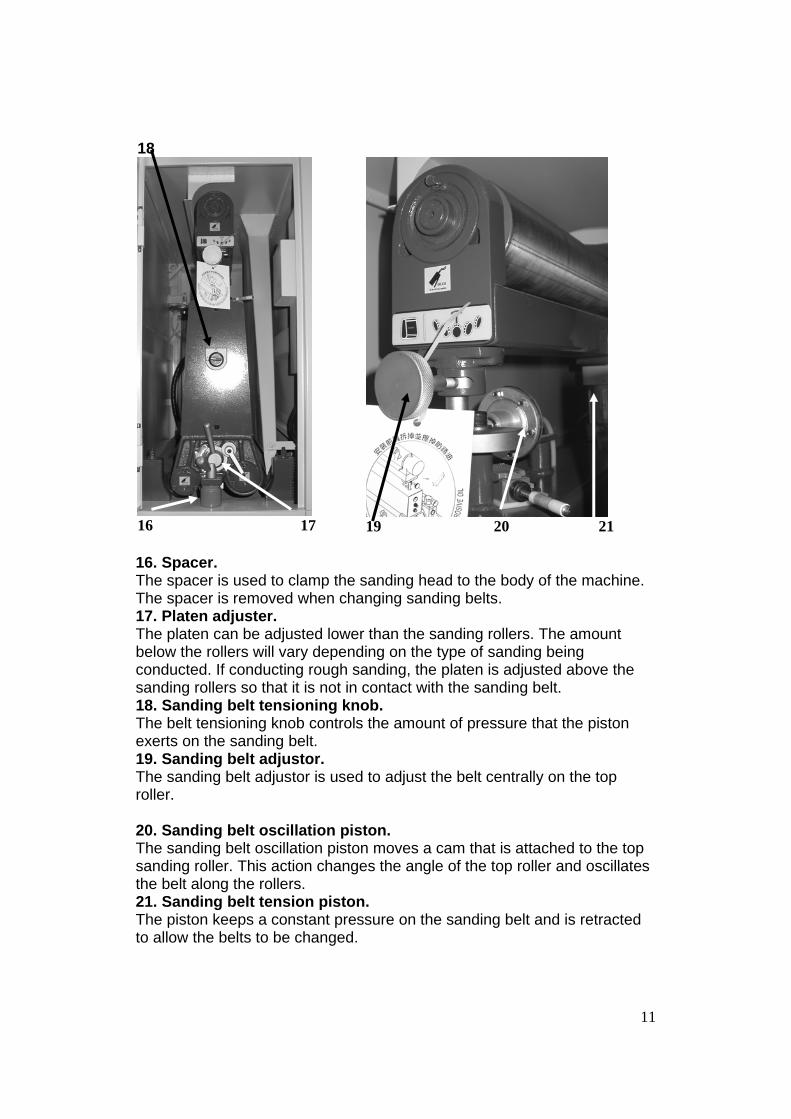
18
16 17
19 20 21
16. Spacer. The spacer is used to clamp the sanding head to the body of the machine. The spacer is removed when changing sanding belts. 17. Platen adjuster. The platen can be adjusted lower than the sanding rollers. The amount below the rollers will vary depending on the type of sanding being conducted. If conducting rough sanding, the platen is adjusted above the sanding rollers so that it is not in contact with the sanding belt. 18. Sanding belt tensioning knob. The belt tensioning knob controls the amount of pressure that the piston exerts on the sanding belt. 19. Sanding belt adjustor. The sanding belt adjustor is used to adjust the belt centrally on the top roller. 20. Sanding belt oscillation piston. The sanding belt oscillation piston moves a cam that is attached to the top sanding roller. This action changes the angle of the top roller and oscillates the belt along the rollers. 21. Sanding belt tension piston. The piston keeps a constant pressure on the sanding belt and is retracted to allow the belts to be changed.

12
What you will receive with the wide belt sander.
Door keys Grease gun flexible extender
Tools Platen extractor Spare ceramic belt limiters
Spare platen backer
Spare platen Graphite pads
Sanding belts
Where to locate your wide belt sander. Before you remove your machine from the packaging, select the area where you will use your machine. There are no hard-and -fast rules for its location, but below are a few guidelines: 1. There should be an area at the front and back of the machine suitable for comfortable working and the length of the work pieces. 2. Adequate lighting. The better the lighting, the more accurately and safely you will be able to work. 3. Solid floor. You should select a solid, flat floor, preferably concrete or something similar. 4. Locate it close to a power source and dust collection. 5. Allow an area for the storage of blanks, finished products and tools.
13
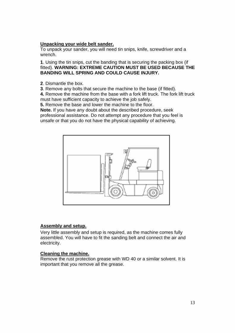
Unpacking your wide belt sander. To unpack your sander, you will need tin snips, knife, screwdriver and a wrench. 1. Using the tin snips, cut the banding that is securing the packing box (if fitted). WARNING: EXTREME CAUTION MUST BE USED BECAUSE THE BANDING WILL SPRING AND COULD CAUSE INJURY. 2. Dismantle the box. 3. Remove any bolts that secure the machine to the base (if fitted). 4. Remove the machine from the base with a fork lift truck. The fork lift truck must have sufficient capacity to achieve the job safely. 5. Remove the base and lower the machine to the floor. Note. If you have any doubt about the described procedure, seek professional assistance. Do not attempt any procedure that you feel is unsafe or that you do not have the physical capability of achieving.
Assembly and setup. Very little assembly and setup is required, as the machine comes fully assembled. You will have to fit the sanding belt and connect the air and electricity. Cleaning the machine. Remove the rust protection grease with WD 40 or a similar solvent. It is important that you remove all the grease.

14
Connecting the electrical supply. Note. A qualified electrician must carry out the installation. Ensure that the main supply corresponds with that of the machine (three-phase 220 V). It is recommended that you use a 60 amp mains breaker. Due to the high amp draw of this machine, it is recommended that the machine is wired directly into the electrical distribution system.
Sanding motor contactor
Cable gland
Conveyor motor overload relay
Sanding motor overload relay
Input power junction block
Amp meter current sensor
Conveyor motor contactor
4 amp fuses
Control system transformer

15
Connecting the air supply.
Air line connection
Air pressure adjuster
Label
The input air regulator regulates the air pressure that is supplied to the machine. The machine is supplied with an air connector, which you can connect your air supply to. You will require an air supply that can deliver a constant minimum pressure of 6 bar. The machine is supplied with an input air regulator that you will need to adjust to 6 bar once you have connected your air supply to the machine. Note. No air pipe is supplied, as the length will depend on your installation. To adjust the air pressure, pull the cap up and rotate until the gauge reads the correct pressure. Once the pressure is adjusted, push the cap in. Note. An air supply of 6 bar minimum is required for the machine. It is strongly recommended that 7 bar be supplied to the machine and that the regulator then be set to 6 bar. This will ensure that the machine always has the minimum required air pressure. The input regulator has a moisture trap that must be empted each day. Note. It is important that the air that is supplied to the machine be clean and dry. The machine will not perform consistently if the air is dirty, as any dirt will block the valves. Wet or damp air will damage your machine and cause inconsistent performance. Note. The pneumatic system does not need any type of lubricant. Some types of lubricant can damage the machine and compromise the machine’s functions. Note. During maintenance, always disconnect the air supply.
16
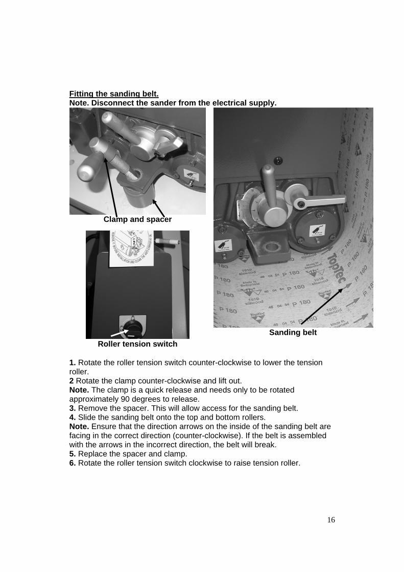
Fitting the sanding belt. Note. Disconnect the sander from the electrical supply.
Clamp and spacer
Roller tension switch
Sanding belt
1. Rotate the roller tension switch counter-clockwise to lower the tension roller. 2 Rotate the clamp counter-clockwise and lift out. Note. The clamp is a quick release and needs only to be rotated approximately 90 degrees to release. 3. Remove the spacer. This will allow access for the sanding belt. 4. Slide the sanding belt onto the top and bottom rollers. Note. Ensure that the direction arrows on the inside of the sanding belt are facing in the correct direction (counter-clockwise). If the belt is assembled with the arrows in the incorrect direction, the belt will break. 5. Replace the spacer and clamp. 6. Rotate the roller tension switch clockwise to raise tension roller.

17
Clamp and spacer assembled
Belt sensor
Sanding belt assembled Note. Never run the sander without the spacer and clamp assembled, as this will damage the machine. Note. The machine is supplied with a sanding belt, and this may not be the correct one for your work. Purchase a number of belts to suit your work and always have spare belts available; you can never predict when a belt will break or wear out. Note. The sanding belt must be positioned centrally on the rollers. It must also be between the forks of the belt sensor.
18
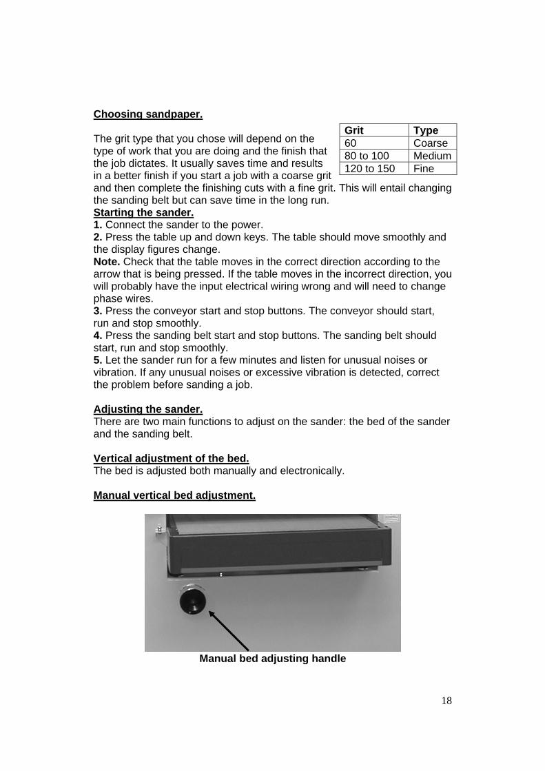
Choosing sandpaper. The grit type that you chose will depend on the type of work that you are doing and the finish that the job dictates. It usually saves time and results in a better finish if you start a job with a coarse grit and then complete the finishing cuts with a fine grit. This will entail changing the sanding belt but can save time in the long run. Starting the sander. 1. Connect the sander to the power. 2. Press the table up and down keys. The table should move smoothly and the display figures change. Note. Check that the table moves in the correct direction according to the arrow that is being pressed. If the table moves in the incorrect direction, you will probably have the input electrical wiring wrong and will need to change phase wires. 3. Press the conveyor start and stop buttons. The conveyor should start, run and stop smoothly. 4. Press the sanding belt start and stop buttons. The sanding belt should start, run and stop smoothly. 5. Let the sander run for a few minutes and listen for unusual noises or vibration. If any unusual noises or excessive vibration is detected, correct the problem before sanding a job. Adjusting the sander. There are two main functions to adjust on the sander: the bed of the sander and the sanding belt. Vertical adjustment of the bed. The bed is adjusted both manually and electronically. Manual vertical bed adjustment.
Manual bed adjusting handle
Grit Type 60 Coarse 80 to 100 Medium120 to 150 Fine
19
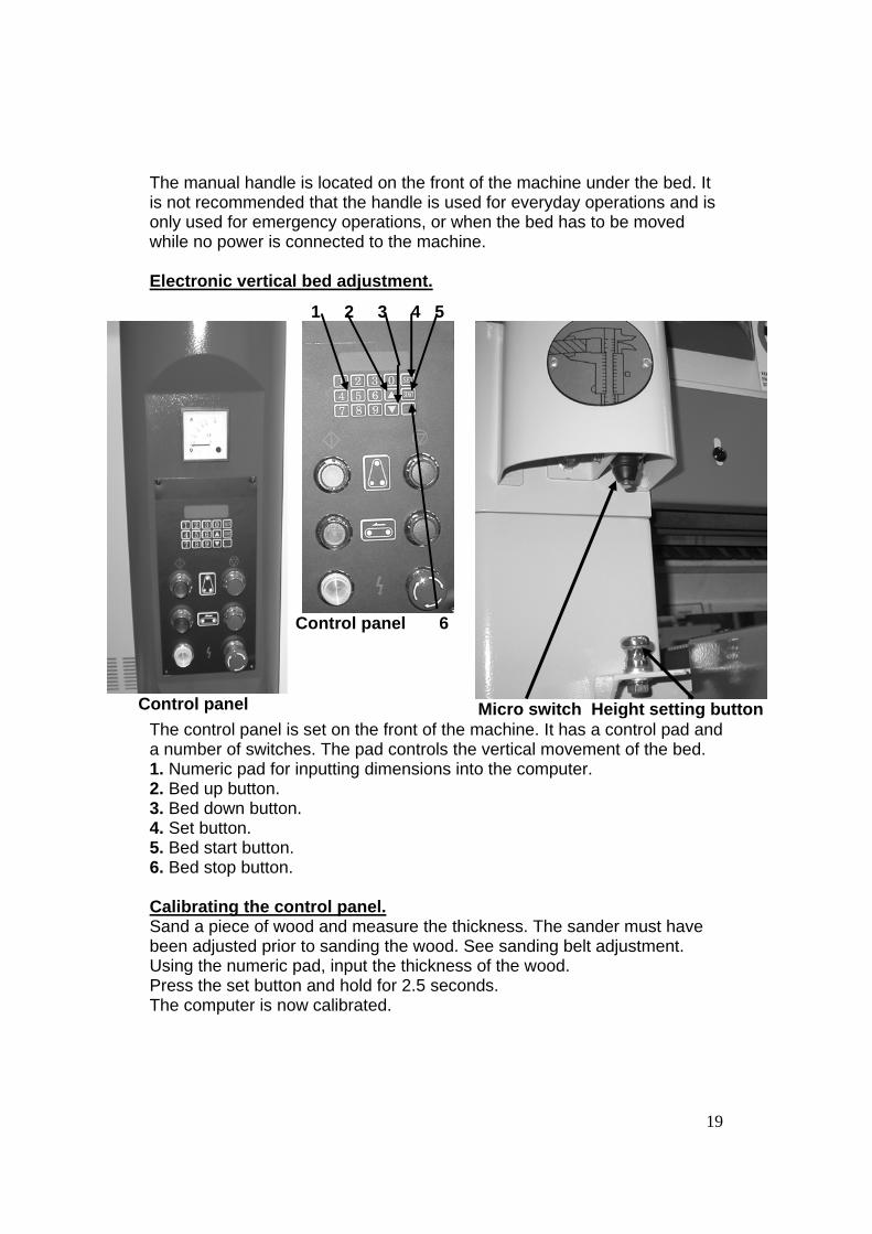
The manual handle is located on the front of the machine under the bed. It is not recommended that the handle is used for everyday operations and is only used for emergency operations, or when the bed has to be moved while no power is connected to the machine. Electronic vertical bed adjustment.
The control panel is set on the front of the machine. It has a control pad and a number of switches. The pad controls the vertical movement of the bed. 1. Numeric pad for inputting dimensions into the computer. 2. Bed up button. 3. Bed down button. 4. Set button. 5. Bed start button. 6. Bed stop button. Calibrating the control panel. Sand a piece of wood and measure the thickness. The sander must have been adjusted prior to sanding the wood. See sanding belt adjustment. Using the numeric pad, input the thickness of the wood. Press the set button and hold for 2.5 seconds. The computer is now calibrated.
Control panel
1 2 3 4 5
Control panel 6
Micro switch Height setting button

20
Setting the depth of cut (sanding depth). Press any button, and the display will read 000.0". Input the depth of cut using the numeric key pad (0,005"). Press the set button and hold for 2.5 seconds. The display will begin to flash; when it stops, the depth of cut is set. Press the start button, and the display will revert to 000.0". The input and run lights will illuminate, and the table will move to the new dimension. A second method of setting the depth of cut is to press the arrow UP button until the depth of cut is reached. Note. If you go past the dimension, press the arrow DOWN button to lower the table. Note. The magnification resolution can be changed by changing the position of a switch that is located on the back of the control panel. This is not recommended, as the machine has been set to suit most workshop usages. Quick set. The sander has a device on the side that is used to set the height of the bed without measuring the job. Simply put the job on the height setting button, press and hold the arrow up button. The table will move up until the job hits the micro switch. The distance between the sanding head and the job is now set. Set the depth of cut as described earlier. Setting the display to metric or inches. Press the set button for 10 seconds, and the display will change from inches to metric, or vice versa. Down limit switch.
Belt speed adjuster Limit switch Limit switch

21
The sander is fitted with a limit switch located at the back of the machine. This limit switch limits the down travel of the bed. Belt speed.
The speed of the belt can be adjusted to between 6 and 30 feet per minute. The speed is infinitely variable to suit the different woods to be sanded. In general, soft woods are sanded faster than hard woods. It is a matter of experience when selecting the correct speed. Change the speed by rotating the belt speed adjuster while the motor is running. Clockwise decreases the speed, while counter-clockwise increases the speed. Note. Never adjust the speed
while the motor is not running, as this will cause damage to the controller. Belt drive gear box. The belt drive gear box is filled with oil. As the oil heats, it expands and causes pressure within the gear box. To relieve this pressure, there is a small hole on the side of the red bolt. To ensure there is no leakage during shipping, the hole is sealed with a small plastic pin. Before the machine is run, this pin must be removed. This will allow the oil to expand without causing damage or leakage during use.
Belt speed adjuster
Blanking pin Red bolt

22
Sanding belt adjustments. General description of sanding controls and actions.
1 2 3 4 5 6 The sanding belt is tensioned by the central belt tension piston. The piston is activated by the sanding belt tension switch. This switch must be activated prior to starting the sander. The sanding belt oscillates along the top and bottom rollers. This greatly enhances the performance of the sander and reduces the chances of lines and marks on the job. To achieve this oscillation, the top roller pivots about a central air cylinder (1). This air cylinder also keeps pressure on the belt and keeps it tight to the rollers. The pivoting is controlled by a non-contact air sensor (4). Should the sanding belt break, a micro switch (3) is activated and stops the machine. If the oscillation
Sanding belt tension switch

23
is excessive or the sanding belt runs off center, the sanding belt will hit one of the two ceramic rollers (2). The rollers are attached to micro switches that stop the machine. The sensitivity of the non-contact air sensor can be adjusted by rotating the control knob (5]) This has been factory set and should not need adjustment. The speed of the belt oscillation can be increased or decreased by adjusting the control knob (6). The sanding belt is centralized on the rollers by adjusting the sanding belt centralizing cam. This will have to be done for every belt, as each belt will run differently. Control panel buttons. 1. Sanding belt start button. 2. Drive belt start button. 3. Sanding belt stop button. 4. Power on light. 5. Drive belt stop button. 6. Emergency stop button (twist to release). Sanding belt oscillation adjustment. 1. With no sanding belt fitted, restrict the airflow across the sensor (U) with a piece of wood or something similar. 2. The top roller should pivot, and when the obstruction is removed, the top roller should pivot back to the original position. 3. Check that the roller pivots a few times.
Sanding belt centralizing cam
1 2 3
4 5 6

24
4. With the sanding belt fitted, run the sanding head and note the time that it takes the sanding belt to oscillate in both directions. The time taken to oscillate in either direction should be the same. 5. If the oscillation to the right is longer than the time for the sanding belt to oscillate to the left, adjust the control knob (5) to the right. 6. The speed of oscillation is adjusted with control knob (6). The speed of oscillation will change the sanding results. Test the sanding results with a piece of scrap. 7. Turning the knob clockwise will reduce the oscillation speed. Running the machine after fitting a new sanding belt. 1. Fit the sanding belt as detailed earlier. 2. Check that the belt is not hitting the ceramic rollers and is positioned approximately central on the rollers. 3. Check that the emergency stop button is not engaged (twist to release). 4. Check that the bed is at least 1 inch down from the sanding belt. 5. Check that the sanding belt tension piston has been activated. 6. Press the sanding belt start button. The sanding belt will start to rotate. 7. Open the left-hand door and check that the sanding belt oscillations are central on the rollers. You will probably find that they are biased to one end. 8. Press the sanding belt stop button. After the belt has completely stopped, loosen the sanding belt centralizing cam and move either left or right depending on the error. 9. You may find that the sanding belt will have hit one of the ceramic rollers. This will mean that the sanding belt is not running central. Release the sanding belt tension piston and re-centralize the belt on the rollers. Then adjust the sanding belt centralizing cam and retest. Note. As the name implies, this is a sanding machine and is not designed to cut large amounts of material from the job. It is far better to take several small slow cuts rather than one large cut. The sanding belt will last far longer, the surface finish will be better and the machine will not be damaged.
25
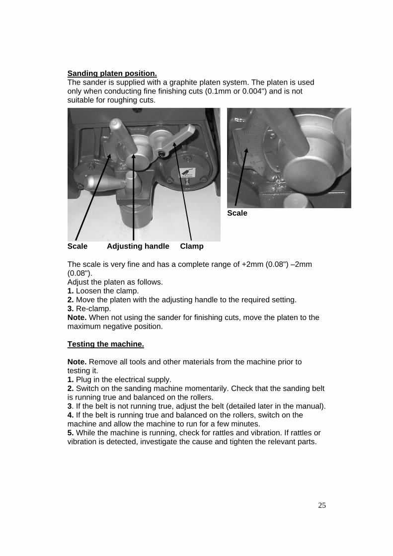
Sanding platen position. The sander is supplied with a graphite platen system. The platen is used only when conducting fine finishing cuts (0.1mm or 0.004") and is not suitable for roughing cuts.
The scale is very fine and has a complete range of +2mm (0.08") –2mm (0.08"). Adjust the platen as follows. 1. Loosen the clamp. 2. Move the platen with the adjusting handle to the required setting. 3. Re-clamp. Note. When not using the sander for finishing cuts, move the platen to the maximum negative position. Testing the machine. Note. Remove all tools and other materials from the machine prior to testing it. 1. Plug in the electrical supply. 2. Switch on the sanding machine momentarily. Check that the sanding belt is running true and balanced on the rollers. 3. If the belt is not running true, adjust the belt (detailed later in the manual). 4. If the belt is running true and balanced on the rollers, switch on the machine and allow the machine to run for a few minutes. 5. While the machine is running, check for rattles and vibration. If rattles or vibration is detected, investigate the cause and tighten the relevant parts.
Scale Adjusting handle Clamp
Scale

26
Check that all the safety switches are functioning.
Bed lower limit switch
Bed safety switch Bed upper limit switch
1. Lower the bed until it hits the lower limit switch. The bed travel must stop once the switch is activated. 2. With the sanding belt and the drive belt running, activate the bed safety switch. The sanding belt and the drive belt must stop once the safety switch has been activated. 3. Raise the bed until it hits the bed upper limit switch. The bed travel must stop once the switch is activated. 4. With the sanding belt and the drive belt running, press the emergency stop button. 5. With the sanding belt running, press the sanding belt stop button. 6. With the drive belt running, press the drive belt stop button. Sanding. Sanding is a finishing process, and no more than 0.008" should be removed with each pass. Larger cuts will result in jamming, poor surface finish, burn marks, excessive sandpaper wear, excessive motor loading, and so on. Wearing the correct safety equipment, start sanding as follows. 1. Switch on the dust collector. 2. Set the bed to a height that will just miss the thickest part of the job. 3. Raise the table with each pass until the job is sanded over the complete surface.
5 6 Emergency stop

27
Maintenance and troubleshooting. Note. When conducting maintenance, disconnect the machine from the electricity and the air supply. General. Keep your machine clean. At the end of each day, clean the machine. Wood contains moisture, and if sawdust is not removed it will cause rust. In general, we recommend that you only use a Teflon-based lubricant. Regular oil attracts dust and dirt. Teflon lubricant tends to dry and has fewer tendencies to accumulate dirt and sawdust. Weekly. 1. Check that all nuts and bolts are tight. 2. Check the sanding belt for damage and wear. 3. Check cables for wear, damage or cuts. 4. Empty the two water traps. 5. Remove any excessive dust and check the dust extraction system for blockages. 6. Grease the bearings. Monthly. 1. All the above. 2. Cover the table adjustment screws with grease. Ensure that the rubber covers are replaced once greasing has been completed. 3. Grease the table lifting chain. After the first 100 hours of operation, replace the oil in the conveyor drive gear box. Repeat the oil change every 2,500 hours. Recommended oil 90 wt gear oil. Drive belt. The drive belts should last for a long time (depending on the usage) but need to be inspected regularly for cracks, cuts and general wear. If damage is found, replace the belts. The belts come factory set, but they should be checked for tension after about 8 hours of use. The belts could need to be re-tensioned, as they will have bedded into the “V” grooves. Note. The sanding head motor has multiple belts. They are matched, so if one belt requires replacement, you must replace all the belts with a matched set. If all the belts are not replaced, this will cause vibration and could put excessive strain on the motor and bearings. Not replacing all the belts will also cause the belts to wear out very quickly, as they are not all the same length and will slip.
28
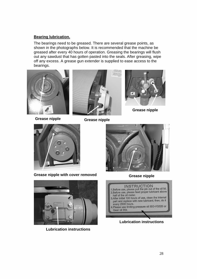
Bearing lubrication. The bearings need to be greased. There are several grease points, as shown in the photographs below. It is recommended that the machine be greased after every 40 hours of operation. Greasing the bearings will flush out any sawdust that has gotten pasted into the seals. After greasing, wipe off any excess. A grease gun extender is supplied to ease access to the bearings.
Grease nipple Grease nipple
Grease nipple
Grease nipple with cover removed
Grease nipple
Lubrication instructions
Lubrication instructions
29
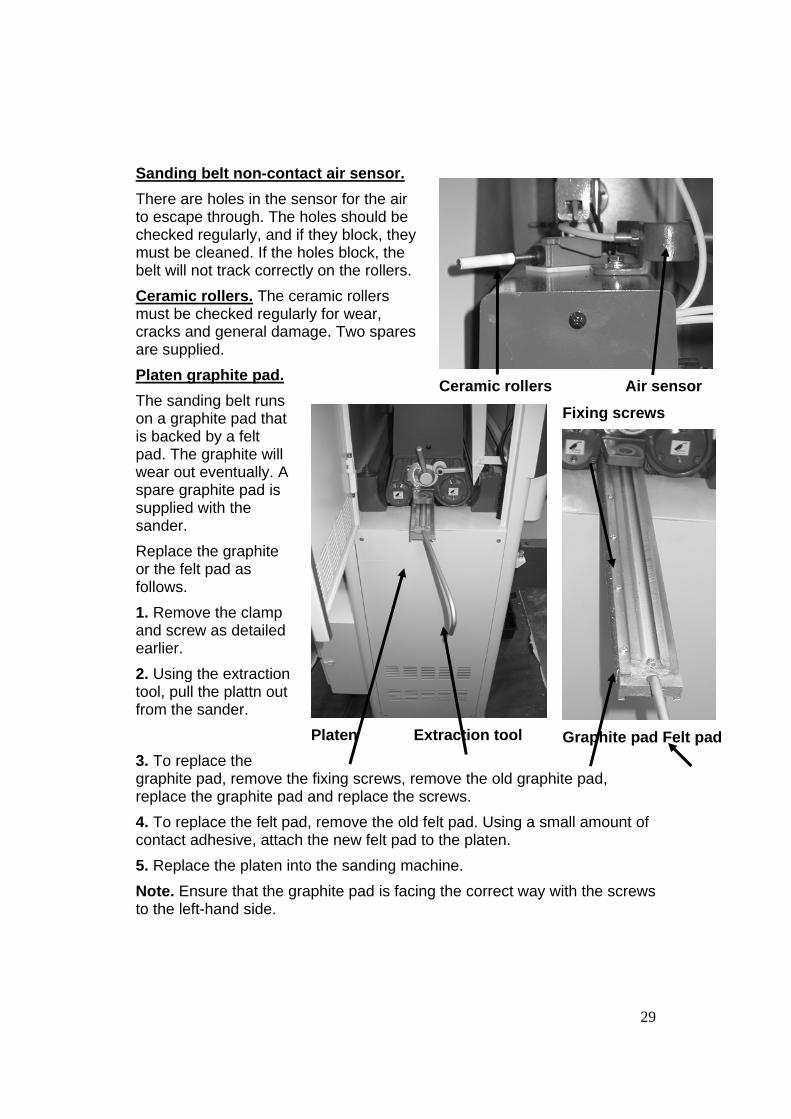
Sanding belt non-contact air sensor. There are holes in the sensor for the air to escape through. The holes should be checked regularly, and if they block, they must be cleaned. If the holes block, the belt will not track correctly on the rollers. Ceramic rollers. The ceramic rollers must be checked regularly for wear, cracks and general damage. Two spares are supplied. Platen graphite pad. The sanding belt runs on a graphite pad that is backed by a felt pad. The graphite will wear out eventually. A spare graphite pad is supplied with the sander. Replace the graphite or the felt pad as follows. 1. Remove the clamp and screw as detailed earlier. 2. Using the extraction tool, pull the plattn out from the sander. 3. To replace the graphite pad, remove the fixing screws, remove the old graphite pad, replace the graphite pad and replace the screws. 4. To replace the felt pad, remove the old felt pad. Using a small amount of contact adhesive, attach the new felt pad to the platen. 5. Replace the platen into the sanding machine. Note. Ensure that the graphite pad is facing the correct way with the screws to the left-hand side.
Ceramic rollers Air sensor
Platen Extraction tool
Fixing screws
Graphite pad Felt pad

30
Pressure roller adjustment.
Pressure roller adjusting screws
There are two pressure rollers: one on the infeed side and the other on the outfeed side of the sanding rollers. The pressure rollers come factory set but may need to be adjusted during the life of the machine. Adjust the rollers as follows. 1. Place a panel on the bed of the sander so that it is under both the infeed and outfeed rollers. 2. Set the bed of the sander vertically so that one of the pressure rollers just touches the panel. 3. Loosen the lock nuts and adjust the pressure rollers so that they are both just touching the panel. This must be completed at the extremities of the rollers to ensure that they are parallel. 4. With the rollers parallel, adjust the rollers to the required setting and lock the lock nuts. Note. When adjusting the height of the pressure rollers, after ensuring that they are parallel, adjust each screw the same amount or the rollers will not be parallel. Note. Adjusting the pressure rollers must be done with the sanding belt stationary. Note. The amount of pressure that you set the pressure rollers to exert on the job will vary depending on such variables as the depth of cut, hardness

31
of the wood and other factors. Experimentation will be required to achieve the correct setting. It is suggested that setting the pressure rollers to 0.020" to 0.030" is a good starting point. Never set the pressure rollers level or higher than the sanding rollers, as this may result in injury. Adjusting the conveyor belt.
Convayor belt adjusting bolt
The conveyor belt comes factory set but may need to be adjusted at some time. The conveyor belt must run centrally on the rollers and must be tensioned to prevent slippage. If the belt is not running centrally, check that the tension is correct before adjusting the tracking. Adjust is as follows. Conveyor tracking adjustment. 1. You may find it easer to remove the steel cover to expose the two guide wheels. To achieve this, remove the fixing screws. 2. Turn the conveyor on. 3. If the conveyor is running to the right, turn the right-hand adjusting screw clockwise. Only make very small adjustments and wait for the conveyor to settle before making additional adjustments. It is better to take your time and not rush the adjustments.

32
4. If the conveyor is running to the left, turn the left-hand adjusting screw clockwise. 5. Once the conveyor is running centrally, stop the conveyor and replace the steel cover. Conveyor tensioning. To increase the tension on the conveyor belt, turn the adjusting bolts clockwise. To reduce the tension on the conveyor belt, turn the adjusting bolts counter-clockwise. Note. Adjust both adjusting bolts exactly the same amount or the tracking will be affected. Motor drive belt adjustment.
Lock nut Break
Sanding head drive motor Adjusting nut Lock nut Conveyor drive motor
Sanding head drive motor belt adjustment. The sanding head drive motor has a break that is activated when the power is removed from the motor. The break is air activated and should not need any regular servicing. The drive belts will need to be adjusted from time to time. To adjust, loosen the lock nut and turn the adjusting nut (under bracket) until the correct tension is achieved. Do not forget to re-tighten the lock nut after the adjusting has been completed. Note. Never access the motor with the power connected to the sander.
33
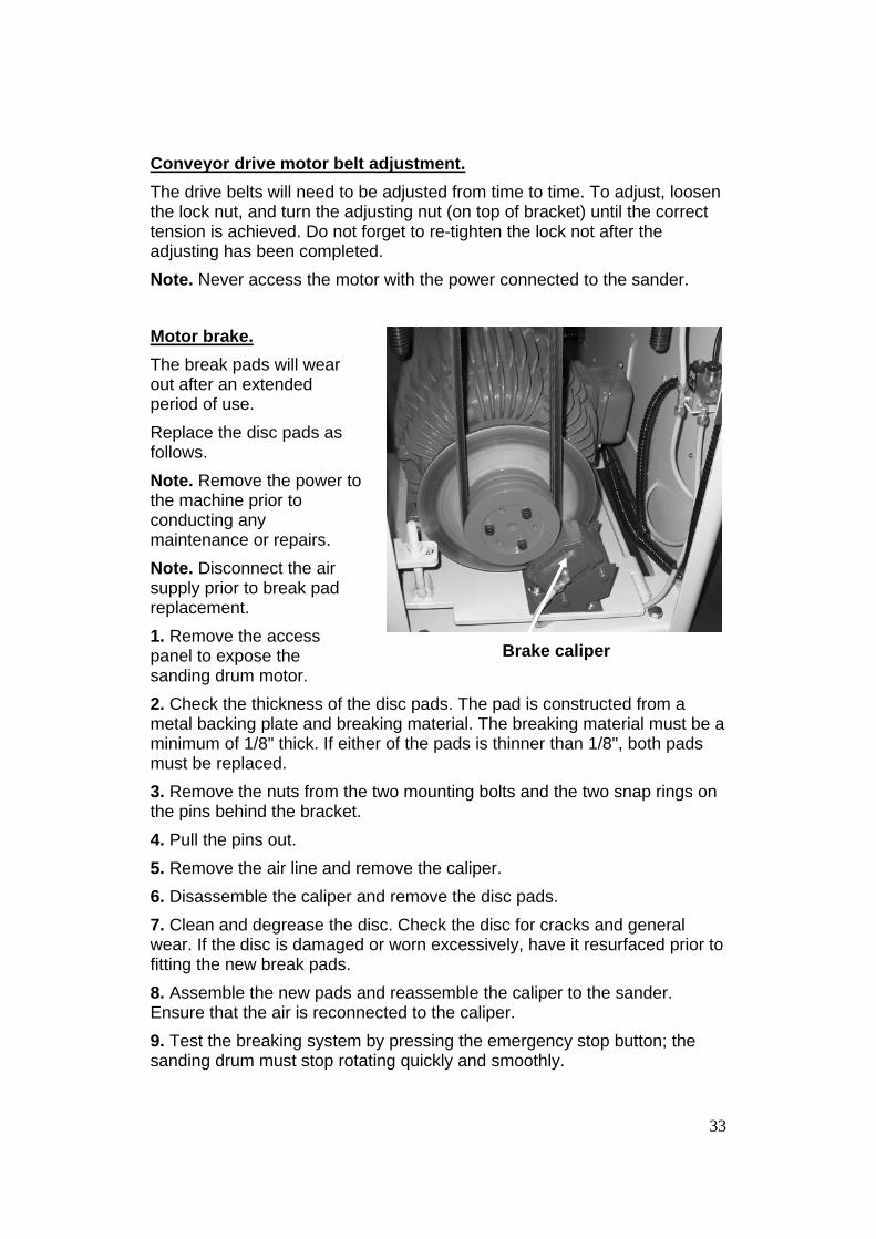
Conveyor drive motor belt adjustment. The drive belts will need to be adjusted from time to time. To adjust, loosen the lock nut, and turn the adjusting nut (on top of bracket) until the correct tension is achieved. Do not forget to re-tighten the lock not after the adjusting has been completed. Note. Never access the motor with the power connected to the sander. Motor brake. The break pads will wear out after an extended period of use. Replace the disc pads as follows. Note. Remove the power to the machine prior to conducting any maintenance or repairs. Note. Disconnect the air supply prior to break pad replacement. 1. Remove the access panel to expose the sanding drum motor. 2. Check the thickness of the disc pads. The pad is constructed from a metal backing plate and breaking material. The breaking material must be a minimum of 1/8" thick. If either of the pads is thinner than 1/8", both pads must be replaced. 3. Remove the nuts from the two mounting bolts and the two snap rings on the pins behind the bracket. 4. Pull the pins out. 5. Remove the air line and remove the caliper. 6. Disassemble the caliper and remove the disc pads. 7. Clean and degrease the disc. Check the disc for cracks and general wear. If the disc is damaged or worn excessively, have it resurfaced prior to fitting the new break pads. 8. Assemble the new pads and reassemble the caliper to the sander. Ensure that the air is reconnected to the caliper. 9. Test the breaking system by pressing the emergency stop button; the sanding drum must stop rotating quickly and smoothly.
Brake caliper

34
Accessing sanding head drive motor electrical termination. To access the motor electrical terminations, remove the cover plate located beside the air regulator. Note. Never access the motor with the power connected to the sander.
Cover plate Motor electrical terminations
(cover plate removed)
35
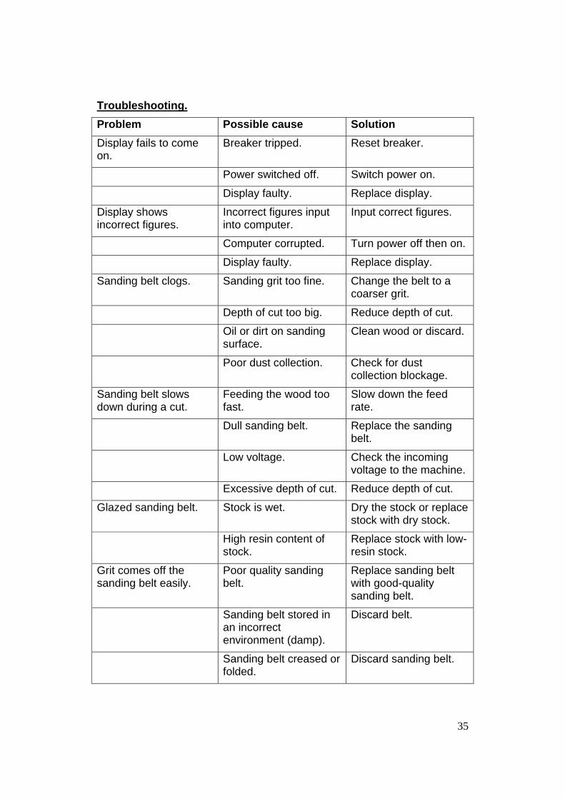
Troubleshooting. Problem Possible cause Solution Display fails to come on.
Breaker tripped. Reset breaker.
Power switched off. Switch power on.
Display faulty. Replace display.
Display shows incorrect figures.
Incorrect figures input into computer.
Input correct figures.
Computer corrupted. Turn power off then on.
Display faulty. Replace display.
Sanding belt clogs. Sanding grit too fine. Change the belt to a coarser grit.
Depth of cut too big. Reduce depth of cut.
Oil or dirt on sanding surface.
Clean wood or discard.
Poor dust collection. Check for dust collection blockage.
Sanding belt slows down during a cut.
Feeding the wood too fast.
Slow down the feed rate.
Dull sanding belt. Replace the sanding belt.
Low voltage. Check the incoming voltage to the machine.
Excessive depth of cut. Reduce depth of cut.
Glazed sanding belt. Stock is wet. Dry the stock or replace stock with dry stock.
High resin content of stock.
Replace stock with low-resin stock.
Grit comes off the sanding belt easily.
Poor quality sanding belt.
Replace sanding belt with good-quality sanding belt.
Sanding belt stored in an incorrect environment (damp).
Discard belt.
Sanding belt creased or folded.
Discard sanding belt.

36
Sanding belt breaks. Belt assembled to machine with arrows in the wrong direction.
Replace belt.
Burn marks on the job. Sanding belt is too fine for the job.
Replace the sanding belt with coarser grit sanding belt.
Sanding belt clogged. Clean belt with belt cleaning stick or replace the sanding belt.
Deep sanding marks or grooves in job.
Sanding belt too coarse.
Replace sanding belt with finer grit.
Clogged sanding belt. Clean or replace sanding belt.
Job has rounded start and/or finish edges.
Excessive depth of cut. Reduce depth of cut.
Sanded job not parallel.
Table not parallel to sanding head.
Adjust the table to sanding head.
Job dented or scratched.
Dirty pressure rollers. Clean pressure rollers.
Job has glazed marks or scratches snaking along the job.
Glazed sanding belt. Clean or replace sanding belt.
Poor sanding results. Worn sanding belt. Replace sanding belt.
Clogged sanding belt. Clean sanding belt and check dust extraction for blockages.
Sander will not start. No power supplied to machine.
Check that the electrical power cord is plugged into the power outlet.
Check that the electrical supply is on (reset the breaker).
With the power disconnected from the machine, check that the wiring to the plug is correct. Check that the rubber insulation is

37
stripped enough and is not causing a bad connection. Check that all the screws are tight.
Check the supply voltage is correct.
Sander will not stop. This is a very rare occurrence, as the machine is designed to fail-safe. If it should occur and you cannot fix the fault, seek professional assistance. The machine must be disconnected from the power and never run until the fault has been rectified.
Switch faulty. Replace the switch.
Motor tries to start but will not turn.
Machine jammed. With the power disconnected from the machine, try to turn the sanding belt by hand. If the sanding belt will not turn, check the reason for the jamming.
Motor faulty. Replace the motor.
Motor break locked on. Release break.
Motor overheats.
The motor is designed to run hot, but should it overheat. It has an internal thermal overload protector that will shut it down until the motor has cooled, and then it will reset automatically. If the motor shuts down consistently, check for the reason.
Wait until motor has cooled and restart.
Dull sanding belt. Replace sanding belt.
Motor cooling fins Clean cooling fins.

38
clogged.
Over-feeding the job. Slow feed rate.
Excessive ambient temperature.
Cool area.
Motor overloaded. Reduce load on motor [(educe depth of cut or feed speed).
Squeaking noise.
Check the bearings. Re-lubricate or replace bearing.
Machine vibrates. Machine not level on the floor.
Re-level the machine, ensuring that it has no movement.
Broken, damaged or defective sanding belt.
Replace the sanding belt.
Loose fixing bolts. Check all the fixing bolts and tighten if found loose.
Respective noise. Damaged V belt(s). Replace V belt(s).
Motor fan hitting the cowl.
Tighten the fan or the cowl.
Part loose. Tighten loose part.
Conveyor belt worn. Replace conveyor belt.
Job slips when sanding.
Greasy or dirty conveyor belt.
Clean conveyor belt.
Excessive depth of cut. Reduce depth of cut.
Conveyor belt worn. Replace conveyor belt.
Pressure roller not exerting correct pressure on job.
Adjust pressure rollers.
Conveyor belt not running in center.
Conveyor belt not tracked.
Adjust conveyor belt.
Conveyor belt worn out. Replace conveyor belt.
Conveyor belt slipping. Incorrect pressure on conveyor belt.
Retention conveyor belt.
Depth of cut too big. Reduce depth of cut.
Conveyor belt dirty. Clean conveyor belt.

39
Conveyor belt contaminated with sawdust.
Clean conveyor belt and check dust extraction for blockages.
Sanding belt hits ceramic switch.
Tracking out of adjustment.
Re-track the sanding belt.
Sanding belt will not track correctly.
Blocked tracking sensor.
Clear sensor blockage.
Oscillation control valve not adjusted correctly (closed).
Adjust oscillation control valve.
Belt not centralized on top roller.
Adjust sanding belt adjuster.
Sanding belt slips on rollers.
Tension cylinder not exerting sufficient pressure.
Check for air leaks. Low air pressure.
Sanding belt will not start.
No tension on the sanding belt.
No air pressure.
Limit switch engaged. Adjust sanding belt.
Emergency stop button engaged.
Reset emergency stop button.
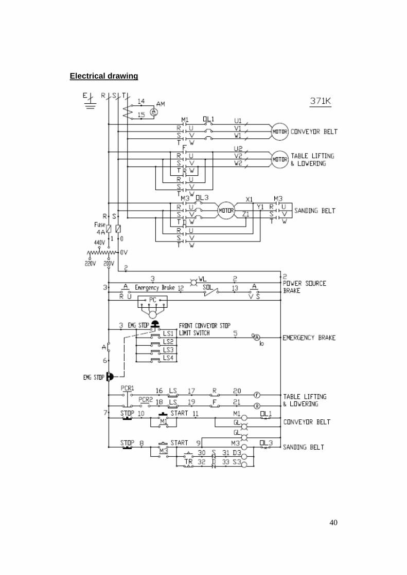
40
Electrical drawing

41
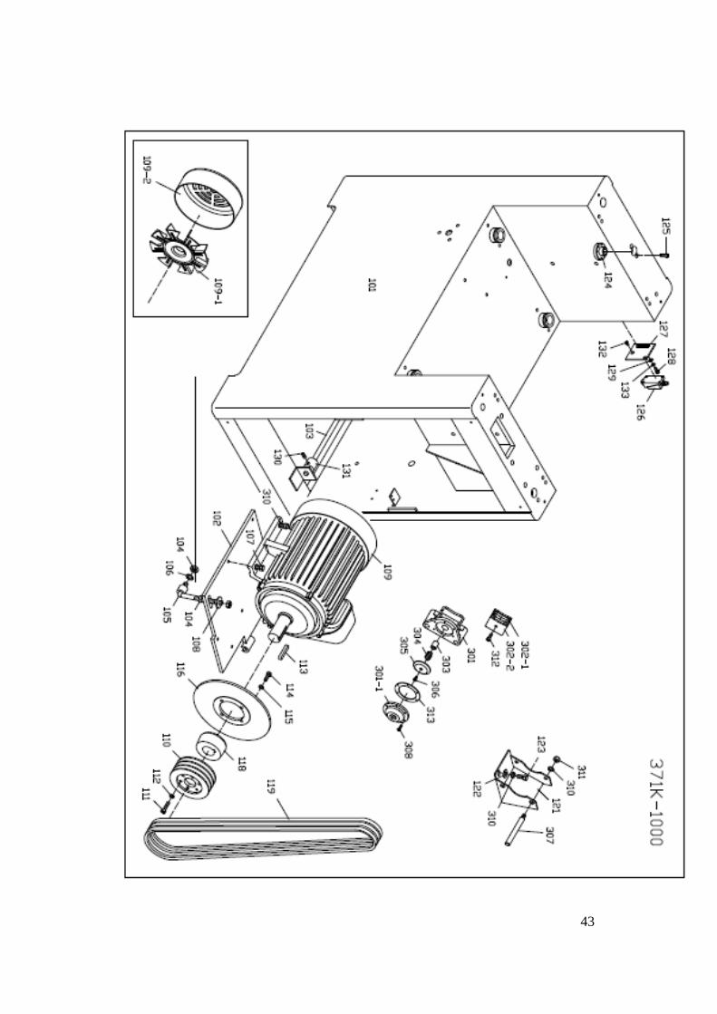
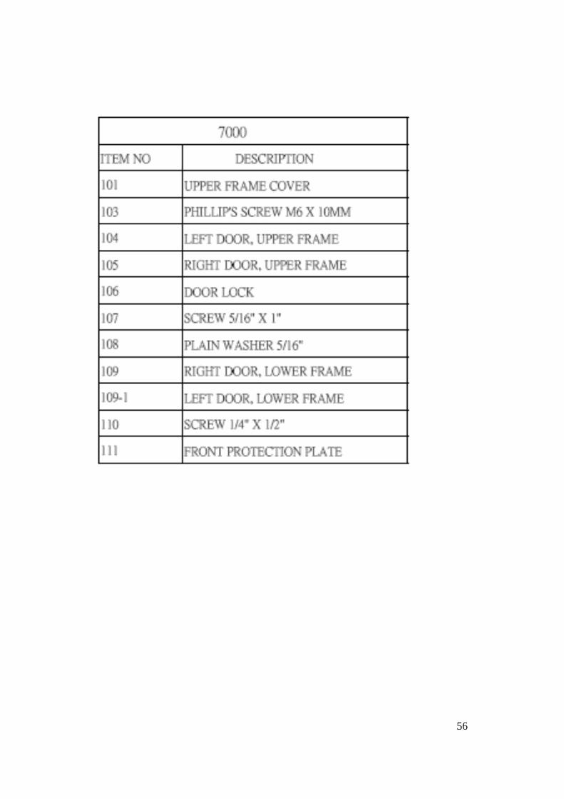
Exploded view drawings.

42
43

44

45

46

47

48

49

50

51

52

53

54

55
56

57

58

59

60