n en scriptio s n stio e repair instructions e structio...
TRANSCRIPT

A WORLD OF COMFORT
ENVEhiclE hEatErs | TeChniCAL DOCuMenTATiOn
tEch
Nic
al d
Escr
ipti
oN
rEpa
ir iN
stru
ctio
Ns
spar
E pa
rts
list
iNst
alla
tioN
sug
gEst
ioN
RepAiR insTRuCTiOns
hyDROniC ii COMFORT
heaters for petrol
B 5 sC – 12 V 20 1928 05 00 00
heaters for diesel
D 5 sC – 12 V 25 2598 05 00 00
thE rEpair iNstructioNs arE Valid for thE followiNg
ENgiNE-iNdEpENdENt watEr hEatErs

2 | VehiCLe heATeRs – TeChniCAL DOCuMenTATiOn
COnTenTs
ChApTeR ChApTeR TiTLe ChApTeR COnTenTs pAge
1 introduction Foreword 5
special text structure, presentation and picture symbols 5
– special text formats and presentations 5
– picture symbols 5
heater documentation 5
– Content and purpose of these troubleshooting and repair instructions 5
Further documentation 5
– Technical description, installation, operating and maintenance instructions 5
– spare parts list 5
emergency shutdown – eMeRgenCy OFF 6
safety instructions for installation and repair 6
Liability claim / guarantee 6
Accident prevention 6
initial start-up of the heater or functional test after a repair 6
2 Function and operation Cutaway view of the hydronic ii Comfort B 5 sC 7
Cutaway view of the hydronic ii Comfort D 5 sC 8
Description of functions 9
– switching on (parking heater mode) 9
– parking heater mode 9
– heating mode 9
– heating at high altitudes 9
Control and safety devices 9
Technical data of the hydronic ii Comfort B 5 sC 10
Technical data of the hydronic ii Comfort D 5 sC 11
3 Troubleshooting What to check first in case of faults 12
Locking the control box 12
– The control box is locked if the following faults occur: 12
– Cancel the control box lock 12
Overview of the test equipment and control units 12
external diagnostics system 12
Fault diagnosis using the eDiTh Basic diagnostics tool 13
– Connect eDiTh Basic 13
– start the diagnosis query. 14
– Delete the fault memory and at the same time cancel the control box lock 14
coNtENts
This list of contents gives you precise information about the contents of
the Troubleshooting and Repair instructions.
if you are looking for a term, technical term or you would like an ab-
breviation explained, please use the relevant index at the end of the
instructions.
VehiCLe heATeRs – TeChniCAL DOCuMenTATiOn | 3
COnTenTs
Fault diagnosis using the control unit 15
– Diagnosis capable control units 15
Query / delete fault memory and cancel the heater lock 15
– Open the easystart Timer and easystart Remote+ workshop menu 15
– easystart Timer / Remote+ service functions 16
easystart select vehicle workshop menu 16
– easystart select service functions 16
4 Repair instructions safety instructions to be noted and followed before working on the heater 22
special tool 22
– AMp release tool 22
hydronic ii Comfort B 5 sC assembly drawing 23
hydronic ii Comfort D 5 sC assembly drawing 24
Repair steps 25
Dismantle the heater 26
Repair step 1 26
– Remove cover 26
Repair step 2 26
– Dismantle water pump 26
Repair step 3 27
– Remove water connection socket 27
Repair step 4 27
– Dismantle metering pump – diesel heater only 27
Repair step 5 28
– Remove “blower” cover 28
Repair step 6 29
– Dismantle metering pump holder – diesel heater only 29
Repair step 7 29
– Dismantle control box 29
Repair step 8 30
– Dismantle overheating sensor and surface sensor 30
– Check overheating sensor 31
– Check the surface sensor 31
Repair step 9 32
– Remove “electric motor” cover and “blower assembly with combustion chamber” 32
Repair step 10 33
– Measure blower speed 33
Repair step 11 34
– Dismantle flame sensor 34
– Check flame sensor 34
– Table of values 34
Repair step 12 35
– Check glow plug 35
– Dismantle glow plug 35

4 | VehiCLe heATeRs – TeChniCAL DOCuMenTATiOn
Measuring the fuel quantity, without eDiTh Basic 36
– preparing for the measurement 36
– Measurement 36
– evaluation 36
Measuring the fuel quantity, with eDiTh Basic 36
– preparing for the measurement 36
– Measurement / evaluation 36
5 electrics / Circuit diagram heater wiring 37
safety instructions for the heater wiring! 37
parts list for heater circuit diagram 37
Circuit diagram, petrol heater 38
Circuit diagram, cable harness, petrol heater 39
Circuit diagram, diesel heater 40
Circuit diagram, cable harness, diesel heater 41
6 environment Certifications 42
Disposal 42
– Disposal of materials 42
– Dismantling the heater 42
– packaging 42
eu Declaration of Conformity 42
7 service List of abbreviations 43
index 43
COnTenTs

VehiCLe heATeRs – TeChniCAL DOCuMenTATiOn | 5
hEatEr documENtatioN
COnTenT AnD puRpOse OF These TROuBLeshOOTing AnD RepAiR
insTRuCTiOns
These instructions are to be used to correct faults and to carry out
repairs on the heater. The work required for this may only be done by
personnel appropriately trained by a Je service partner.
furthEr documENtatioN
TeChniCAL DesCRipTiOn, insTALLATiOn, OpeRATing AnD MAinTe-
nAnCe insTRuCTiOns
This documentation provides the Je service partner with all the neces-
sary technical information, describes the correct installation in accord-
ance with the regulations and provides the customer with the necessary
information for safe operation of the heater.
spARe pARTs LisT
The spare parts list provides the Je service partner with the necessary
information for ordering spare parts in case of repairs.
forEword
These Troubleshooting and Repair instructions are applicable to the
heaters listed on the title page, to the exclusion of all liability claims.
Depending on the version or change status of the heater, there may be
differences between it and these troubleshooting and repair instruc-
tions.
The user must check this before carrying out the repair work and, if
necessary, take the differences into account.
spEcial tExt structurE, prEsENtatioN aNd picturE symbols
special text formats and picture symbols are used in these instructions
to emphasise different situations and subjects. please refer to the fol-
lowing examples for their meanings and appropriate action.
speCiAL TexT FORMATs AnD pResenTATiOns
� This dot (�) indicates a list, which is introduced by a heading.
– if an indented dash (–) follows a “dot”, this list is a sub-section of
the black dot.
underlined blue text denotes a cross-reference, which can be clicked
in the pDF format. The part of the document named in the text is then
displayed.
piCTuRe syMBOLs
daNgEr!This information points out a potential serious or fatal danger. ignoring
this information can result in severe injuries.
Î This arrow indicates the appropriate precaution to take to avert the
danger.
attENtioN!This information points out a dangerous situation for a person and / or
the product. Failure to comply with these instructions can result in inju-
ries to people and / or damage to machinery.
Î This arrow indicates the appropriate precaution to take to avert the
danger.
plEasE NotE!These remarks contain recommendations for use and useful tips for the
operation, installation and repair of the heater.
1 inTRODuCTiOn

6 | VehiCLe heATeRs – TeChniCAL DOCuMenTATiOn
iNitial start-up of thE hEatEr or fuNctioNal tEst aftEr a
rEpair
� After installing or carrying out a repair on the heater, the coolant cir-
cuit and the whole fuel supply system must be vented carefully.
� Comply with the instructions issued by the vehicle manufacturer.
� Open all heating circuits before the trial run (set the temperature
control to “warm”).
� During the heater trial run, all water and fuel connections must be
checked for leaks and secure, tight fit.
� if faults occur while the heater is running, use a diagnostic unit to
correct the cause of the fault.
EmErgENcy shutdowN – EmErgENcy off
if an emergency shutdown – eMeRgenCy OFF – is necessary during
operation, proceed as follows:
� switch the heater off at the control unit or
� remove the fuse or
� disconnect the heater from the battery.
safEty iNstructioNs for iNstallatioN aNd rEpair
attENtioN!improper installation or repair of eberspächer heaters can cause a fire
or result in toxic exhaust entering the inside of the vehicle.
This can cause serious and even fatal risks.
Î The heater may only be installed according to the specifications in
the technical documents or repaired using original spare parts by
authorised and trained persons.
Î installation and repairs by unauthorised and untrained persons,
repairs using non-original spare parts and without the technical
documents required for installation and repair are dangerous and
therefore are not permitted.
Î A repair may only be carried out in connection with the respective
unit-related technical description, installation instructions, operat-
ing instructions and maintenance instructions.
This document must be carefully read through before / during in-
stallation and repair and followed throughout. particular attention is
to be paid to the official regulations, the safety instructions and the
general information.
plEasE NotE! � The relevant rules of sound engineering practice and any information
provided by the vehicle manufacturer are to be observed during the
installation and repair.
� When carrying out electric welding on the vehicle, the positive cable
at the battery should be disconnected and placed at ground to pro-
tect the control box.
liability claim / guaraNtEE
eberspächer does not accept any liability for defects and damage,
which are due to installation or repair by unauthorised and untrained
persons.
Compliance with the official regulations and the safety instructions is
prerequisite for liability claims.
Failure to comply with the official regulations and safety instructions
leads to exclusion of any liability of the heater manufacturer.
accidENt prEVENtioN
general accident prevention regulations and the corresponding work-
shop and operating safety instructions are to be observed.
1 inTRODuCTiOn

VehiCLe heATeRs – TeChniCAL DOCuMenTATiOn | 7
cutaway ViEw of thE hydroNic ii comfort b 5 sc
WE
WA
WA
B
V A
3
2
1
7
6
8
12
11
10
9
54
13
1 electric motor
2 glow plug
3 Combustion air blower
4 Metering pump
5 switching element
6 Water pump
7 Control box
8 Overheating sensor
9 surface sensor
10 heat exchanger
11 Flame tube
12 Combustion chamber
13 exhaust silencer
A = exhaust
B = Fuel
V = Combustion air
WA = Water discharge
We = Water inlet
2 FunCTiOn AnD OpeRATiOn

8 | VehiCLe heATeRs – TeChniCAL DOCuMenTATiOn
cutaway ViEw of thE hydroNic ii comfort d 5 sc
WE
WA
WA B
V A
3
4
2
1
7
6
8
12
11
10
9
5
13
1 electric motor
2 glow plug
3 Combustion air blower
4 Metering pump
5 switching element
6 Water pump
7 Control box
8 Overheating sensor
9 surface sensor
10 heat exchanger
11 Flame tube
12 Combustion chamber
13 exhaust silencer
A = exhaust
B = Fuel
V = Combustion air
WA = Water discharge
We = Water inlet
2 FunCTiOn AnD OpeRATiOn

VehiCLe heATeRs – TeChniCAL DOCuMenTATiOn | 9
coNtrol aNd safEty dEVicEs
� if, 100 seconds after being switched on for petrol heaters and 70
seconds after being switched on for diesel heaters, the heater does
not ignite, the start is repeated.
The heater is automatically shut down if, after three further start
attempts in the case of a petrol / ethanol heaters and two attempts
with a diesel heater, the heater fails to start within the preset safety
period (240 seconds).
After an impermissible number of failed start attempts, the control
box is locked.*
� if the flame goes out independently during operation, the heater is
restarted and if necessary, a maximum of two further start attempts
are made within the preset safety time.
if the heater does not ignite or ignites but goes out again within 15
minutes, a safety lock-out occurs.
The safety lock-out can be cancelled by briefly switching off and on
again (heater On / OFF).
� in the event of overheating (e.g. lack of water, poorly vented cooling
water circuit), the overheating sensor triggers, the fuel feed is inter-
rupted and the heater is switched off automatically. Once the cause
of the overheating has been eliminated, the heater can be restarted
by switching it off and on again (heater On / OFF).
Requirement: the heater is sufficiently cooled, cooling water tem-
perature < 70 °C. After an impermissible number of shut-downs on
overheating the control box is locked*.
� if the lower or upper voltage limit is reached, the heater is shut down
automatically.
� The heater does not start up if the glow plug is defective or if the
electric cable to the metering pump is interrupted.
� The speed of the blower motor is monitored continuously. if the
blower motor does not start up, if it is blocked or if the speed falls
below 40 % of the desired speed, the heater is shut down automati-
cally after 60 sec.
* Cancellation of the lock or reading out errors is possible
– with the easystart Timer,
– with the easystart Remote+ radio remote control,
– with the easystart Call radio remote control
– with the easystart select control unit,
– using the eDiTh Basic diagnostics tool.
Operation and fault list from page 9.
plEasE NotE!Do not repeat the switching off / on routine more than twice.
dEscriptioN of fuNctioNs
sWiTChing On (pARking heATeR MODe)
pARking heATeR MODe
When the heater is switched on, the symbol appears in the control
unit or the operating display lights up.
heATing MODe
The water pump starts up and, following a preset sequence, the com-
bustion air blower, glow plug and metering pump are started.
The glow plug is switched off once a stable flame has formed in the
combustion chamber.
Depending on the heat requirements, the heater runs at the follow-
ing levels: power – high – Low – Off (pause mode). The temperature
thresholds for these are permanently programmed in the electronic
control box.
if the coolant liquid is cold, the heater starts in control stage “high” and
if necessary switches to the “power” control stage. if the coolant liquid
is hot, the start takes place in “Low” control stage.
After the water temperature has reached approx. 75 °C – depending
on the selected blower setting – the heater switches to “high” control
stage.
if the water temperature continues to rise up to 80 °C, the heater
switches to “Low” control stage.
� if the heat output achieved in “Low” control stage is insufficient,
the water temperature drops to 70 °C – the heater switches back to
“high” control stage.
� if the heating output in the “Low” control stage is sufficient the
heater remains in “Low” control stage. if the water temperature rises
to 85 °C, the heater switches to the “Off” control stage (pause mode)
and then starts the afterrun.
� if the water temperature cools to 75 °C during pause mode, a con-
trolled start follows in “Low” control stage.
During pause mode the water pump continues to run and the On
symbol continues to be displayed in the control unit.
heATing AT high ALTiTuDes
When using the heater at high altitudes, please note:
� heating at altitudes up to 1500 m:
– unlimited heating possible.
� heating at altitudes over 1500 m – 3000 m:
– The heater can be run for short periods (e.g. driving through a
mountain pass or taking a break in your journey).
– During longer stays, e.g. winter camping, the fuel supply must be
adjusted to the altitude.
The altitude adjustment can be made by installing an air pressure
sensor. The air pressure sensor is included in the altitude kit –
order no. 22 1000 33 22 00.
2 FunCTiOn AnD OpeRATiOn

10 | VehiCLe heATeRs – TeChniCAL DOCuMenTATiOn
tEchNical data of thE hydroNic ii comfort b 5 sc
heater type hydronic ii
heater version B 5 sC
heating medium Mixture of water and anti-freeze
(proportion of antifreeze at least 10 % up to 50 % maximum)
Fuel petrol – standard commercially available (Din 51600 and en 228)
e85 ethanol fuel (en 51625)
Rated voltage 12 volt
Control of the heat flow power high Low
heat flow (watt) 5200 5000 2300
Fuel consumption (l/h) 0.72 0.69 0.32
Average electrical power consumption (watt)
during operation 50 47 22
while starting 130
Operating range
Lower voltage limit:
An undervoltage protection installed in the control box switches off
the heater if the lower voltage limit is reached.
10.5 V
upper voltage limit:
An overvoltage protection installed in the control box switches off the
heater if the upper voltage limit is reached.
16 V
Allowable operating pressure up to 2.5 bar overpressure max.
Water volume in the heater approx. 0.25 l
Minimum water flow rate of the heater >250 l/h
Allowable ambient temperature During operation
–40 °C to +60 °C
Without operation
–40 °C to +105 °Cheater, continuous
heater, short time – – – +125 °C (5 x 2 h)
Temperature, coolant liquid
continuous –40 °C to +120 °C –40 °C to +120 °C
short time – – – +125 °C (1 h)
interference suppression class 5 (en 55025)
Weight – without coolant and attachments approx. 2.7 kg
attENtioN!Operating the heater outside the specified technical data can cause
malfunctions.
Î The technical data must be complied with at all times.
plEasE NotE!if no limit values are given, the technical data listed is with the usual
heater tolerances of ± 10 % at nominal voltage and esslingen reference
altitude.
2 FunCTiOn AnD OpeRATiOn

VehiCLe heATeRs – TeChniCAL DOCuMenTATiOn | 11
tEchNical data of thE hydroNic ii comfort d 5 sc
heater type hydronic ii
heater version D 5 sC
heating medium Mixture of water and anti-freeze
(proportion of antifreeze at least 10 % up to 50 % maximum)
Fuel Diesel – standard commercially available (en 590)
Blending with max. 20 % FAMe according to en 14214 is permitted
Rated voltage 12 volt
Control of the heat flow power high Low
heat flow (watt) 5200 5000 2100
Fuel consumption (l/h) 0.64 0.61 0.26
Average electrical power consumption (watt)
during operation 50 47 22
while starting 130
Operating range
Lower voltage limit:
An undervoltage protection installed in the control box switches off
the heater if the lower voltage limit is reached.
10.5 V
upper voltage limit:
An overvoltage protection installed in the control box switches off the
heater if the upper voltage limit is reached.
16 V
Allowable operating pressure up to 2.5 bar overpressure max.
Water volume in the heater approx. 0.25 l
Minimum water flow rate of the heater >250 l/h
Allowable ambient temperature During operation
–40 °C to +80 °C
Without operation
–40 °C to +105 °Cheater, continuous
heater, short time – – – +125 °C (5 x 2 h)
Temperature, coolant liquid
continuous –40 °C to +120 °C –40 °C to +120 °C
short time – – – +125 °C (1 h)
interference suppression class 5 (en 55025)
Weight – without coolant and attachments approx. 2.9 kg
attENtioN!Operating the heater outside the specified technical data can cause
malfunctions.
Î The technical data must be complied with at all times.
plEasE NotE!if no limit values are given, the technical data listed is with the usual
heater tolerances of ± 10 % at nominal voltage and esslingen reference
altitude.
2 FunCTiOn AnD OpeRATiOn

12 | VehiCLe heATeRs – TeChniCAL DOCuMenTATiOn
oVErViEw of thE tEst EquipmENt aNd coNtrol uNits
The electronic control box can store up to 5 faults, which can be read
out and displayed.
The following test equipment / control units can be used to query the
fault memory in the control box and if necessary to delete the locking of
the control box:
testing equipment order no. � eDiTh Basic diagnostics tool
can be used from software
version s3V10-F.
The software can be downloaded
from the service portal.
Also required:
for easystart T / easystart R+
Adapter cable
for easystart Call
Adapter cable
22 1541 89 00 00
22 1000 33 78 00
22 1000 34 11 00
control unit order no. � easystart Timer 22 1000 34 15 00
� easystart Remote+
� easystart select
� easystart Call
22 1000 34 17 00
22 1000 34 13 00
22 1000 34 01 00
plEasE NotE! � The diagnostics cable (cable 0.5² BuWh) must also be connected if
using control units.
if the fault memory cannot be read out, check the diagnostics cable
is properly laid and is not damaged.
ExtErNal diagNostics systEm
if an external, vehicle-specific diagnostics system is used please
consult the vehicle manufacturer.
what to chEck first iN casE of faults
� check
– Fuel in the tank?
– Fuel lines leaking? (visual check)
– in the case of diesel heaters, summer diesel still in the fuel lines?
– heating control (water valve) fully set to “WARM”?
– Combustion air system or exhaust system damaged or blocked?
� Electrical components
– Cables, connections damaged?
– Contacts corroded?
– Fuses defective?
– incorrect wiring? (short circuit, interruption)
� check battery voltage
– Battery voltage < 10 volt, the undervoltage protection has triggered.
– Battery voltage > 16 volt, the overvoltage protection has triggered.
� check voltage supply ubatt (terminal 30)
Disconnect the 10-pin connector -xs2 / -xB2 and measure the ap-
plied voltage in connector -xB2 between chamber 1 (cable 2.5² RD)
and chamber 2 (cable 2.5² Bn).
if it differs from the battery voltage, check the fuses, the supply
cables, the ground connection and the positive (plus) support point
on the battery for voltage drop (corrosion / interruption).
lockiNg thE coNtrol box
The COnTROL BOx is LOCkeD iF The FOLLOWing FAuLTs OCCuR:
� too many attempted starts
if the heater carries out several consecutive unsuccessful start
attempts Fault code 050 is displayed – the control box is locked.
� overheating
if the heater overheats several times in succession Fault code 015 is
displayed – the control box is locked.
CAnCeL The COnTROL BOx LOCk
Cancellation of the control box lock depends on the appropriate test
equipment and is described from page 12.
3 TROuBLeshOOTing

VehiCLe heATeRs – TeChniCAL DOCuMenTATiOn | 13
fault diagNosis usiNg thE Edith basic diagNostics tool
plEasE NotE! � Always connect in the given order!
� The plug-in “diagnosis” connection may not be disconnected until
the heater has been switched off and the after-running has finished!
� Check whether version s3V10-F of the eDiTh software required for
the diagnosis has been installed on the pC, if necessary the version
can be downloaded from the service portal.
� Follow the operating instructions for the eDiTh Basic (isO adapter)
diagnostics tool.
� When the plug-in “diagnosis” connection (A) is disconnected the volt-
age supply for the control unit is retained.
� Fault code, fault description, cause / remedial action are described
from page 17.
COnneCT eDiTh BAsiC
1. Disconnect the plug-in “diagnosis” connection (A) in the heater
cable harness (F).
2. Connect 3-pin connector housing (1) of the adapter cable (B) to the
plug-in “diagnosis” connection (A).
3. Connect the 6-pin receptacle housing (2) of the adapter cable (B)
with the 6-pin tab connector housing (3) of the eDiTh Basic diag-
nostics tool (C).
4. Connect the suB-D connection cable (e) to the eDiTh Basic diag-
nostics tool (C) and to the pC (D).
A
B
C D
G
E
1 2
3
F
A plug-in “diagnosis” connection
B Adapter cable
C eDiTh Basic diagnostics tool
D pC
e sub-D connection cable
F heater cable harness
g usB adapter
1 3 pin connector housing of adapter cable
2 6 pin receptacle housing of adapter cable
3 6-pin tab connector housing of eDiTh Basic diagnostics tool
3 TROuBLeshOOTing
14 | VehiCLe heATeRs – TeChniCAL DOCuMenTATiOn
sTART The DiAgnOsis QueRy.
� Double-click the ‹eDiTh› icon on the Desktop to start the diagnostic
software The eDiTh start window opens.
� Double-click the ‹flame› button ‹heaters and test selection› win-
dow opens.
– select the heater by its ‹Version no.› or via the ‹Automatic search›.
� in the ‹Test› window, double-click ‹general Data +Fault Memory› to
open the ‹Fault memory› window.
– The fault code of the current fault/error and the fault codes of
faults/errors F1 – F5 are displayed.
DeLeTe The FAuLT MeMORy AnD AT The sAMe TiMe CAnCeL The
COnTROL BOx LOCk
� in the “Fault memory” window, press the “Delete fault memory”
button in the menu bar.
– The whole fault memory is deleted and the control box is
unlocked.
3 TROuBLeshOOTing

VehiCLe heATeRs – TeChniCAL DOCuMenTATiOn | 15
plEasE NotE! � Further information and current circuit diagrams of the control units
are available in the “installation instructions plus", which can be
downloaded from www.eberspaecher-standheizung.com/download.
� The BuWh diagnostics cable must be connected in order to carry out
the diagnosis. To this end, note and follow the circuit diagram of the
control unit and of the heater.
� if the diagnostics cable is not connected, the “Diagnosis” menu is
blocked.
� not only the defective component, but also a defective current circuit
results in a fault being displayed.
� Fault code, fault description, cause / remedial actions are described
from page 15.
� ensure sufficient battery voltage (min. 10.5 volt).
quEry / dElEtE fault mEmory aNd caNcEl thE hEatEr lock
Open The eAsysTART TiMeR AnD eAsysTART ReMOTe+ WORkshOp
Menu
Display On, the start display appears.
use the or button to select the symbol in the Menu bar.
10:30
Mo.
Confirm the seTTings menu item by pressing the button.
press the LOngpRess button for longer than 5 sec.; the Workshop
menu is displayed.
use the or button to select menu items.
use the or button to select settings.
press the button to confirm the selection.
press the button to exit the workshop menu.
fault diagNosis usiNg thE coNtrol uNit
DiAgnOsis CApABLe COnTROL uniTs
Easystart timer, order no. 22 1000 34 15 00
Easystart remote+, order no. 22 1000 34 17 00
Easystart select, order no. 22 1000 34 13 00
if faults occur in the heater while it is running, they are displayed with
“err” after the mobile unit or timer has been activated.
The current fault and the stored faults “F1“ to “F5“ can be queried.
3 TROuBLeshOOTing

16 | VehiCLe heATeRs – TeChniCAL DOCuMenTATiOn
eAsysTART seLeCT seRViCe FunCTiOns
menu item service function
1_1: Display current fault
Note:
heater must be switched on.
The AF display and the digits of the current fault are
displayed alternately. The current fault is always writ-
ten in fault memory F1.
“ndi” is displayed if no diagnostics cable is connected.
1_2: Read out fault memory F1 – F5
Note:
heater must be switched on.
The F1 display and the digits of the error code are
displayed alternately.
use the or button to display error memory
F2 – F5.
“ndi” is displayed if no diagnostics cable is connected.
1_3: Delete fault memory F1 – F5
Note:
heater must be switched on.
press the button to confirm the DeL display.
“ndi” is displayed if no diagnostics cable is connected.
eAsysTART TiMeR / ReMOTe+ seRViCe FunCTiOns
menu item service function
1.1.1: heater 1 – display current fault
Note
The heater must be switched on to detect current
faults.
1.1.2: heater 2 – display current fault
Note
The heater must be switched on to detect current
faults.
1.2.1: heater 1 – read out fault memory F1 – F5
Display:
Fault memory F1 – F5 with error code, e.g.: F1: 12.
1.2.2: heater 2 – read out fault memory F1 – F5
Display:
Fault memory F1 – F5 with error code, e.g.: F1: 12.
1.3.1: heater 1 – delete fault memory F1 – F5
press button to delete.
1.3.2: heater 2 – delete fault memory F1 – F5
press button to delete.
Easystart sElEct VEhiclE workshop mENu
The service functions listed in the following can be displayed, read out
and / or changed via the vehicle workshop menu.
Opening The VehiCLe WORkshOp Menu
Display On, the start display appears.
start display
water heater
start display
air heater
press button and at the same time for longer than 5 sec.
The workshop menu is displayed.
use the or button to select menu items.
use the or button to select settings.
press the button to confirm menu items.
exit the workshop menu via Timeout.
3 TROuBLeshOOTing

VehiCLe heATeRs – TeChniCAL DOCuMenTATiOn | 17
fault codE
display
fault dEscriptioN commENts
� rEmEdial actioN
000 no faults — —
009 implausible air pressure information Communication loss between the control box and air pressure sensor.
� Read out air pressure sensor fault memory (only with eDiTh Basic diagnostics tool, soft-
ware s3V7-F and higher).
� Check wiring and plug-in connections, if ok replace air pressure sensor.
010 shutdown due to overvoltage
(heater not functioning)
Overvoltage applied to control box for at least 20 seconds without interruption.
� Disconnect plug-in connection -xB3/-xs5, vehicle engine on, measure voltage at con-
nector -xB2 – between chamber 1, cable 2.5² RD and chamber 2, cable 2.5² Bn. Voltage
>15 volt check the generator regulator, check battery.
011 shutdown due to undervoltage
(heater not functioning)
undervoltage applied to control box for at least 20 seconds without interruption.
� Vehicle engine off, disconnect plug-in connection -xB2/-xs2, measure voltage at con-
nector -xB2 – between chamber 1, cable 2.5² RD and chamber 2, cable 2.5² Bn. if the
voltage is <10 volt , check the fuses, the supply cables, the ground connections and
the positive support point at the battery for voltage drop (corrosion).
012 Overheating – software threshold
exceeded
Temperature at overheating sensor >125 °C
� Check water circuit:
– heating control in max. position.
– Check water circuit for leaks.
– Vent water circuit.
– if non-return valve / thermostat in the water circuit, check the flow direction.
� Check water throughput rate.
� Check overheating sensor:
– Check cable for continuity, short circuit and damage.
– Measure the resistive value at the control box connector – between chamber 10,
cable 0.5² Bk and chamber 11, cable 0.5² Bk, see see page 31 for measured
values.
� Check water pump, see Fault code 041 and 042.
013
014
Temperature difference error (be-
fore metering pump delivery)
possible overheating risk
(1. differential evaluation)
plEasE NotE!Fault code 014 is only displayed if
the heater is running and the water
temperature at the overheating
sensor has reached at least 80 °C.
Difference between the temperature values of the overheating sensor and the surface sen-
sor is too large.
� For remedial action see Fault code 012.
� Check the surface sensor:
– Check cable for continuity, short circuit and damage.
– Measure the resistive value at the control box connector – between chamber 7, cable
0.5² Wh and chamber 8, cable 0.5² Wh, see see page 31 for measured values.
015 Operating lock-out – too many
overheating events detected
The control box is locked due to too frequent consecutive overheating (Fault code 012,
013, 014, 016).
� For remedial action see Fault code 012.
� Cancel the control box lock, see from page 12.
3 TROuBLeshOOTing

18 | VehiCLe heATeRs – TeChniCAL DOCuMenTATiOn
fault codE
display
fault dEscriptioN commENts
� rEmEdial actioN
016 possible overheating risk
(2. differential evaluation)
plEasE NotE!Fault code 016 is only displayed if
the heater is running and the water
temperature at the overheating
sensor has reached at least 80 °C.
Difference between the temperature values of the overheating sensor and the surface sen-
sor is too large.
� For remedial action see Fault code 012.
� Check the surface sensor:
– Check cable for continuity, short circuit and damage.
– Measure the resistive value at the control box connector – between chamber 7, cable
0.5² Wh and chamber 8, cable 0.5² Wh, see see page 31 for measured values.
017 Overheating, hardware threshold
exceeded
Temperature at overheating sensor >130 °C
� For remedial action see Fault code 012.
� Check the surface sensor:
– Check cable for continuity, short circuit and damage.
– Measure the resistive value at the control box connector – between chamber 7, cable
0.5² Wh and chamber 8, cable 0.5² Wh, see see page 31 for measured values.
018
019
glow plug – start energy too low
glow plug – ignition energy too low
glow plug energy input is too low.
� perform functional check on the glow plug, see Fault code 020.
020
021
022
glow plug – interruption
glow plug – overload
glow plug - short circuit down-
stream of +ub or transistor error
cautioN!The glow plug is irreparably dam-
aged if the voltage values are
exceeded.
Î perform the functional check
with max. 9.5 volt.
plEasE NotE!ensure the power pack has ad-
equate short-circuit resistance.
� Check cable for continuity, short circuit and damage.
� perform functional check on the glow plug in installed condition.
– Control box connector – chamber 3, cable 1.5² Bn and chamber 6, cable 1.5² Wh,
unclip both cables.
– Apply 9.5 V ±0.1 V voltage to the glow plug and after 25 sec measure the current
intensity.
– if 9.5 A (+1 A / –1.5 A) the glow plug is ok.
– if values are different, renew the glow plug.
025 k-line – short circuit � Check the diagnostics cable:
Connector -xB2 – chamber 5 and connector s8 – chamber 2, check cable 0.5² BuWh
for continuity, short circuit and damage, if ok replace control box, see from Fault
code 090.
3 TROuBLeshOOTing

VehiCLe heATeRs – TeChniCAL DOCuMenTATiOn | 19
fault codE
display
fault dEscriptioN commENts
� rEmEdial actioN
030 speed of the burner motor is out-
side the allowable range
cautioN!The motor is irreparably damaged if
the voltage values are exceeded.
Î perform the functional check
with max. 8.2 volt.
plEasE NotE! � ensure correct connection of the
plus (positive) and minus (nega-
tive) cables.
� ensure the power pack has ad-
equate short-circuit resistance.
impeller blocked (frozen, soiled, sluggish, ...)
� Remove blockage and check the burner motor for ease of movement by manually turn-
ing the impeller.
� Make a mark (white paint) on the impeller and measure the speed using a non-contact
r.p.m. counter, see page 33.
unclip control box connector – chamber 13, cable 0.75² Bk and chamber 14, cable
0.75² Bn, take the speed measurement with max. 8.2 volt (+ 0.2 volt).
– speed <10000 rpm renew the combustion air blower.
– speed > 10000 rpm renew the control box.
031
032
035
Burner motor - interruption
Burner motor - short circuit
Burner motor - short circuit down-
stream of +ub or transistor error
cautioN!The motor is irreparably damaged if
the voltage values are exceeded.
Î perform the functional check
with max. 8.2 volt.
plEasE NotE! � ensure correct connection of the
plus (positive) and minus (nega-
tive) cables.
� ensure the power pack has ad-
equate short-circuit resistance.
� Check burner motor cable:
Check control box connector – chamber 13, cable 0.75² Bk and chamber 14, cable
0.75² Bn for continuity, short circuit and damage.
� Take the speed measurement of the burner motor with max. 8.2 volt (+ 0.2 volt), see
Fault code 030.
038
039
Vehicle blower - interruption
Vehicle blower - short circuit
� Check “blower” lead harness:
Check connector -xB2 – chamber 3, cable 0.5² BkRD and chamber 2, cable 2.5² Bn for
continuity, short circuit and damage, if ok renew relay (2.5.7.).
040 Vehicle blower - short circuit down-
stream of +ub or transistor error
� pull off relay (-k1), if fault code 038 is displayed, the relay is defective renew relay
(-k1).
041
042
Water pump – interruption
Water pump – short circuit
� Check “water pump” lead harness:
Check control box connector – chamber 12, cable 0.75² VT and chamber 9, cable 0.75²
Bn for continuity, short circuit and damage, if ok renew water pump.
043 Water pump - short circuit down-
stream of +ub or transistor error
� pull off connector at water pump, if fault code 041 is displayed the water pump is
defective renew water pump.
3 TROuBLeshOOTing

20 | VehiCLe heATeRs – TeChniCAL DOCuMenTATiOn
fault codE
display
fault dEscriptioN commENts
� rEmEdial actioN
047
048
Metering pump – short circuit
Metering pump interruption
� Check “metering pump” lead harness:
if petrol heater:
Check connector -xB2 – chamber 4, cable 0.75² gn and chamber 10, cable 0.75² Bngn
for continuity, short circuit and damage, if ok renew metering pump.
if diesel heater:
Check control box connector – chamber 4, cable 0.75² gn and chamber 5, cable 0.75²
Bngn for continuity, short circuit and damage, if ok renew metering pump.
049 Vehicle blower – short circuit down-
stream of +ub or transistor error
� Disconnect connector connection of “metering pump” cable loom or unplug the plug at
the metering pump, if Fault code 048 is displayed the metering pump is defective
renew the metering pump.
050 Operating lock-out – too many
safety timeouts
Too many start attempts, the control box is locked.
� Cancel the control box lock, see from page 12.
� Check fuel quantity and fuel supply, see from page 36.
051 Cold air – timeout On starting the flame sensor signals a temperature >70 °C for longer than 240 sec.
� Check exhaust and combustion air system.
� Check flame sensor, see Fault code 064 and 065.
052 safety time exceeded � Check exhaust and combustion air system.
� Check fuel quantity and fuel supply, see from page 36.
� Renew the fuel filter inserted in the connection socket of the metering pump.
053
054
056
057
Flame cutout from “power”
control stage
Flame cutout from “high"
control stage
Flame cutout from “Low”
control stage
Flame cutout from start process
plEasE NotE!if start attempts are still allowed,
in the event of a flame cutout the
heater restarts, if necessary with
subsequent repeat start.
if the restart or repeated start was
successful, the fault code display
is deleted.
� Check exhaust and combustion air system.
� Check fuel quantity and fuel supply, see from page 36.
� Check flame sensor, see Fault code 064 and 065.
060 Overheating sensor interruption � Check overheating sensor:
– Check control box connector – chamber 10, cable 0.5² Bk and chamber 11, cable
0.5² Bk for damage.
– Dismantle and check overheating sensor, see page 31.
– if fault code 060 continues to be displayed, replace the control box.
3 TROuBLeshOOTing

VehiCLe heATeRs – TeChniCAL DOCuMenTATiOn | 21
fault codE
display
fault dEscriptioN commENts
� rEmEdial actioN
061 short circuit in overheating sensor � Check overheating sensor:
– Check control box connector – chamber 10, cable 0.5² Bk and chamber 11, cable
0.5² Bk for damage.
– Dismantle and check overheating sensor, see page 31.
– if fault code 061 continues to be displayed, replace the control box.
062
063
printed circuit board sensor – inter-
ruption
printed circuit board sensor – short
circuit
� Replace control box
064 Flame sensor interruption � Check flame sensor:
– Check control box connector – chamber 1, cable 0.22² Bn and chamber 2, cable
0.22² Bn for damage.
– Dismantle and check flame sensor, see page 34.
– if fault code 064 continues to be displayed, replace the control box.
065 short circuit in flame sensor � Check flame sensor:
– Check control box connector – chamber 1, cable 0.22² Bn and chamber 2, cable
0.22² Bn for damage.
– Dismantle and check flame sensor, see page 34.
– if fault code 065 continues to be displayed, replace the control box.
069 Je communication error � Check diagnostics cable
– Connector -xB2 – chamber 5 and connector s8 – chamber 2, check cable 0.5² BuWh
for continuity, short circuit and damage, if ok check the components connected to
the diagnostics cable , if ok replace the control box.
071 surface sensor – interruption � Check the surface sensor:
– Check control box connector – chamber 7, cable 0.5² Wh and chamber 8, cable 0.5²
Wh for damage.
– Dismantle and check surface sensor, see page 31.
– if fault code 071 continues to be displayed, replace the control box.
072 surface sensor – short circuit � Check the surface sensor:
– Check control box connector – chamber 7, cable 0.5² Wh and chamber 8, cable 0.5²
Wh for damage.
– Dismantle and check surface sensor, see page 31.
– if fault code 072 continues to be displayed, replace the control box.
074 Operating lock-out – overheating
detected, hardware is defective
� Check overheating sensor:
– Check cable for continuity, short circuit and damage.
– Check control box connector – chamber 10, cable 0.5² Bk and chamber 11, cable
0.5² Bk for damage.
– Dismantle and check overheating sensor, see page 31.
– if fault code 074 continues to be displayed, replace the control box.
� Cancel the control box lock, see from page 12.
090 hardware is defective Replace control box
091 Too many resets Check voltage supply
092 – 099 Control box defective Replace control box
3 TROuBLeshOOTing

22 | VehiCLe heATeRs – TeChniCAL DOCuMenTATiOn
spEcial tool
AMp ReLeAse TOOL
The AMp release tool is used to release plug-in contacts in a connector
housing.
This release tool can be ordered directly from AMp.
� For Micro Timer AMp Order no. 0-0539960-1
� For Junior power Timer AMp Order no. 1-1579007-6
� For standard timer,
Junior timer AMp Order no. 1-1579007-4
The permitted repair work to the heater is described in the “Repair instruc-
tions“ chapter. The heater must be removed from the vehicle for the repair
work to be carried out.
The heater is assembled in the reverse order, note and follow any
additional instructions.
plEasE NotE!After completing all the work and installing the heater in the vehicle,
carry out a functional check on the heater.
safEty iNstructioNs to bE NotEd aNd followEd bEforE
workiNg oN thE hEatEr
daNgEr!risk of iNjury, burNs aNd poisoNiNg!
Î Always switch off the heater beforehand and leave it to cool.
Î Disconnect the battery.
Î The heater must not be operated in closed rooms such as garages
or workshops.
exception:
exhaust suction available directly at the entry to the exhaust pipe.
cautioN! Î The seals of dismantled components must be renewed.
Î During repair work, check all components for damage and if neces-
sary replace.
Î Check connector contacts, plug-in connections and cables for cor-
rosion and damage and if necessary repair.
Î Only ever use eberspächer spare parts if replacements are neces-
sary.
Î After working on the coolant circuit, the level of the coolant must
be checked and if necessary topped up according to the vehicle
manufacturer's instructions.
Î The coolant circuit must then be vented.
Î Operation or the after running of the heater may only be stopped in
an emergency (see “eMeRgenCy OFF” on page 6) by interrupt-
ing the battery current (risk of heater overheating).
4 RepAiR insTRuCTiOns

VehiCLe heATeRs – TeChniCAL DOCuMenTATiOn | 23
hydroNic ii comfort b 5 sc assEmbly drawiNg
parts list
1 Jacket with heat exchanger
2 Control box
3 heater lead harness with overheating sensor and surface sensor
4 Combustion chamber
5 Flame sensor
6 glow plug
7 Water pump
8 Cover
9 Cover, electric motor
10 Blower
11 Cover, blower, with seal
12 seal, combustion chamber / blower
13 seal, combustion chamber / heat exchanger
14 screw, M4 x 12 (2x)
15 Compression spring, overheating sensor
16 Compression spring, surface sensor
17 grommet, fuel pipe
18 grommet, blower cover
19 seal, flame sensor
20 grommet
21 grommet, control box cable loom
22 hose clamp
23 screw, M5 x 80 (4x)
24 screw, M5 x 55 (3x)
25 O-ring, 18 x 2
26 O-ring, 16 x 2
27 O-ring, 14 x 2.6
28 screw, M4 x 16 (4x)
29 plug
24
24
24 29
20
21
725
263
5
19
6
2
27
1414
1615
1
22
18
11
28
28
10
9
17
4
12
23
23
23
23
13
28
28
8
4 RepAiR insTRuCTiOns

24 | VehiCLe heATeRs – TeChniCAL DOCuMenTATiOn
hydroNic ii comfort d 5 sc assEmbly drawiNg
24
24
24 31
20
21
725
26
3
30
5
19
6
2
27
1414
1615
1
22
29
18
28
28
10
11
9
17
4
12
23
23
23
23
13
28
28
8
parts list
1 Jacket with heat exchanger
2 Control box
3 heater lead harness with overheating sensor and surface sensor
4 Combustion chamber
5 Flame sensor
6 glow plug
7 Cover, control box
8 Cover, metering pump
9 Cover, electric motor
10 Blower
11 Cover, blower, with seal
12 seal, combustion chamber / blower
13 seal, combustion chamber / heat exchanger
14 screw, M4 x 12 (2x)
15 Compression spring, overheating sensor
16 Compression spring, surface sensor
17 grommet, fuel pipe
18 grommet, blower cover
19 seal, flame sensor
20 grommet
21 grommet, control box cable loom
22 hose clamp
23 screw, M5 x 80 (4x)
24 screw, M5 x 55 (3x)
25 O-ring, 18 x 2
26 O-ring, 16 x 2
27 O-ring, 14 x 2.6
28 screw, M4 x 16 (4x)
29 Metering pump, preassembled
30 holder, metering pump
31 plug
4 RepAiR insTRuCTiOns

VehiCLe heATeRs – TeChniCAL DOCuMenTATiOn | 25
coNNEctor assigNmENt – 10-piN coNNEctor -xs2
Battery “minus”, cable 2.5² Bn
Battery “plus”, cable 2.5² RD
Metering pump “plus”, cable 0.75² gn
(for petrol heater only)
Vehicle blower, cable 0.5² BkRD
Auxiliary heating criterion, cable 0.5² Bu
Diagnostics, cable 0.5² BuWh
switch on “plus”, cable 0.5² ye
Metering pump “minus”, cable 0.75² Bngn
(for petrol heater only)
coNNEctor assigNmENt – 14-piN coNNEctor, coNtrol box
Water pump “plus”, cable 0.5² VT
Water pump “minus”, cable 1² Bn
Metering pump “minus”, cable 0.75² Bngn
(for diesel heater only)
Metering pump “minus”, cable 0.75²
gn (for diesel heater only)
Flame sensor, cable 0.22², Bn
Flame sensor, cable 0.22², Bn
glow plug, cable 1.5² Bn
glow plug, cable 1.5² Wh
surface sensor, cable 0.5² Wh
surface sensor, cable 0.5² Wh
Overheating sensor, cable 0.5² Bk
Overheating sensor, cable 0.5² Bk
Burner motor, cable 0.75² Bk
Burner motor, cable 0.75² Bn
Connector housings are shown from the lead entry side.
rEpair stEps
plEasE NotE!This repair instruction describes how to dismantle the heater in indi-
vidual repair steps. Reference is made to the necessary preceding steps
to be carried out at the relevant repair steps.
repair step 1
Remove cover page 26
repair step 2
Dismantle water pump page 26
repair step 3
Remove water connection socket page 27
repair step 4
Dismantle metering pump – diesel heater only page 27
repair step 5
Remove “blower” cover page 28
repair step 6
Dismantle metering pump holder – diesel heater only page 29
repair step 7
Dismantle control box page 29
repair step 8
Dismantle overheating sensor and surface sensor page 30
Check overheating sensor page 31
Check the surface sensor page 31
repair step 9
Remove “electric motor” cover and
“blower assembly with combustion chamber” page 32
repair step 10
Measure blower speed page 33
repair step 11
Dismantle flame sensor page 34
Check flame sensor page 34
repair step 12
Check glow plug page 35
Dismantle glow plug page 35
4 RepAiR insTRuCTiOns

26 | VehiCLe heATeRs – TeChniCAL DOCuMenTATiOn
rEpair stEp 2
DisMAnTLe WATeR puMp
To remove the cover, complete Repair step 1 first.
� unscrew 4 fixing screws M4 x 55.
� Lift the water pump carefully and, together with the water connection
socket, pull out of the jacket.
� Disconnect the lead harness from the water pump.
� Remove the water pump.
3
3
2
1 1
3
4
1
petrol heater
11
3
2
4
1
3
Diesel heater
1 Drillholes for M4 x 55 fixing screws
2 “Water pump” lead harness
3 Water connection
4 Water pump
plEasE NotE!nOTes FOR The AsseMBLy:
� Before installing the water pump, renew the two O-rings of the water
connection sockets.
� Before installing the water pump, ensure that the “fuel pipe” grom-
met and the “control box cable loom” grommet are positioned
correctly.
� Tightening torque of the fixing screws:
M4 x 55 = 2.9+0.3 nm
dismaNtlE thE hEatEr
rEpair stEp 1
ReMOVe COVeR
� use a screwdriver to unlock the cover on both sides.
� Remove cover.
1
petrol heater
1
Diesel heater
1 Cover
4 RepAiR insTRuCTiOns

VehiCLe heATeRs – TeChniCAL DOCuMenTATiOn | 27
rEpair stEp 4
DisMAnTLe MeTeRing puMp – DieseL heATeR OnLy
To dismantle the “metering pump”, complete Repair step 1 and Repair
step 2 first.
2
1
5
3
6
4
1 use a screwdriver to open the hose clamp.
2
3
4
1
2 pull the hose bend off the fuel pipe.
1 5
3 pull off the 2-pin connector (5) at the metering pump.
rEpair stEp 3
ReMOVe WATeR COnneCTiOn sOCkeT
swivel the water connection socket upwards by approx. 45° and pull it
out of the water pump.
2
3
4
1
1 Water pump
2 Water connection socket, swivelled through 45° and pulled out
3 switching element
4 O-ring
plEasE NotE!nOTes FOR The AsseMBLy:
� Before installing the water pump, renew the O-ring of the water con-
nection socket.
� Before installing the water connection socket, ensure that the
switching element is inserted in the correct installation position in
the water pump.
4 RepAiR insTRuCTiOns

28 | VehiCLe heATeRs – TeChniCAL DOCuMenTATiOn
rEpair stEp 5
ReMOVe “BLOWeR” COVeR
To remove the “blower” cover, complete Repair step 1 and Repair step 2
first, in case of a diesel heater, complete Repair step 4 also.
� unscrew 4 fixing screws M4 x 16.
� Remove the “blower” cover carefully above the fuel connection.
1
1
3
1
2
1
petrol heater
1
1
3
1
2
1
Diesel heater
1 M4 x 16 fixing screw
2 “Blower” cover
3 Fuel connection
plEasE NotE!nOTes FOR The AsseMBLy:
� Renew fuel connection grommet in the “lower” cover. The grommet
is included in the corresponding spare parts kit.
� Carefully position the “blower” cover above the fuel connection on
the blower cover. ensure that the motor connection cables do not get
clamped between the cover and housing.
� ensure the “fuel connection” grommet fits correctly in the “blower”
cover.
� ensure the “electric motor cable loom” grommet fits correctly in the
blower housing.
� Tightening torque of the fixing screws M4 x 16 = 2.9+0.3 nm
4 1
4 pull the preassembled metering pump out of the holder (4).
1 Metering pump
2 hose bend
3 hose clamp
4 holder, metering pump
5 2-pin connector, metering pump
6 grommet, metering pump
plEasE NotE!nOTes FOR The AsseMBLy:
� When installing the metering pump, ensure that the “metering pump”
grommet is positioned correctly.
4 RepAiR insTRuCTiOns
VehiCLe heATeRs – TeChniCAL DOCuMenTATiOn | 29
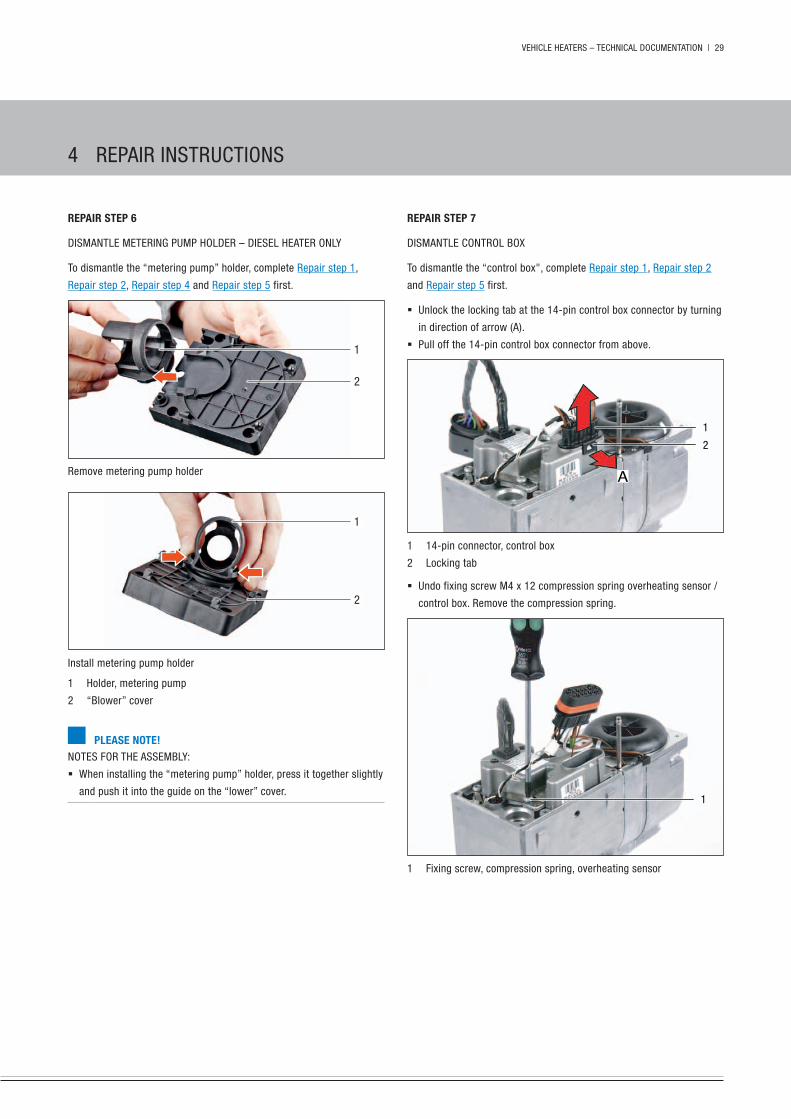
rEpair stEp 7
DisMAnTLe COnTROL BOx
To dismantle the “control box", complete Repair step 1, Repair step 2
and Repair step 5 first.
� unlock the locking tab at the 14-pin control box connector by turning
in direction of arrow (A).
� pull off the 14-pin control box connector from above.
1
2
A
1 14-pin connector, control box
2 Locking tab
� undo fixing screw M4 x 12 compression spring overheating sensor /
control box. Remove the compression spring.
1
1 Fixing screw, compression spring, overheating sensor
rEpair stEp 6
DisMAnTLe MeTeRing puMp hOLDeR – DieseL heATeR OnLy
To dismantle the “metering pump” holder, complete Repair step 1,
Repair step 2, Repair step 4 and Repair step 5 first.
1
2
Remove metering pump holder
1
2
install metering pump holder
1 holder, metering pump
2 “Blower” cover
plEasE NotE!nOTes FOR The AsseMBLy:
� When installing the “metering pump” holder, press it together slightly
and push it into the guide on the “lower” cover.
4 RepAiR insTRuCTiOns
30 | VehiCLe heATeRs – TeChniCAL DOCuMenTATiOn
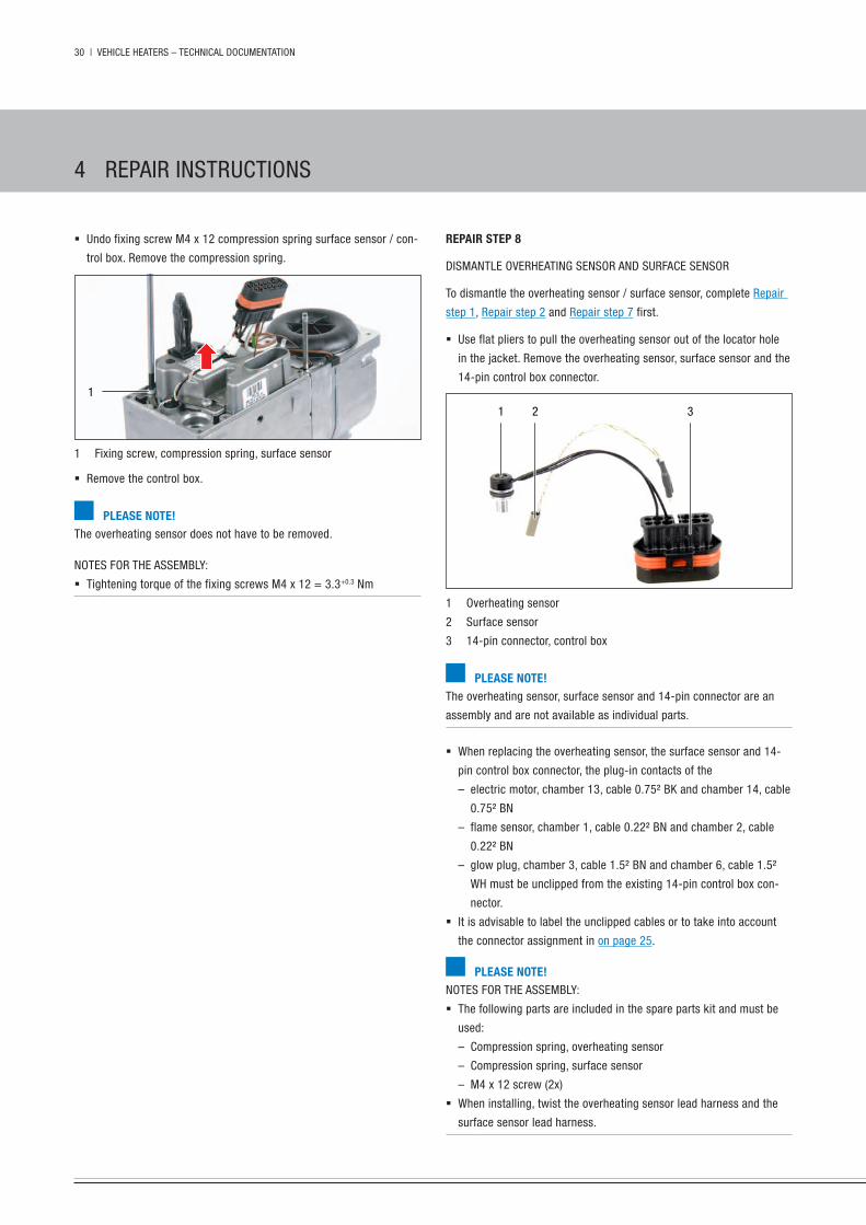
rEpair stEp 8
DisMAnTLe OVeRheATing sensOR AnD suRFACe sensOR
To dismantle the overheating sensor / surface sensor, complete Repair
step 1, Repair step 2 and Repair step 7 first.
� use flat pliers to pull the overheating sensor out of the locator hole
in the jacket. Remove the overheating sensor, surface sensor and the
14-pin control box connector.
1 2 3
1 Overheating sensor
2 surface sensor
3 14-pin connector, control box
plEasE NotE!The overheating sensor, surface sensor and 14-pin connector are an
assembly and are not available as individual parts.
� When replacing the overheating sensor, the surface sensor and 14-
pin control box connector, the plug-in contacts of the
– electric motor, chamber 13, cable 0.75² Bk and chamber 14, cable
0.75² Bn
– flame sensor, chamber 1, cable 0.22² Bn and chamber 2, cable
0.22² Bn
– glow plug, chamber 3, cable 1.5² Bn and chamber 6, cable 1.5²
Wh must be unclipped from the existing 14-pin control box con-
nector.
� it is advisable to label the unclipped cables or to take into account
the connector assignment in on page 25.
plEasE NotE!nOTes FOR The AsseMBLy:
� The following parts are included in the spare parts kit and must be
used:
– Compression spring, overheating sensor
– Compression spring, surface sensor
– M4 x 12 screw (2x)
� When installing, twist the overheating sensor lead harness and the
surface sensor lead harness.
� undo fixing screw M4 x 12 compression spring surface sensor / con-
trol box. Remove the compression spring.
1
1 Fixing screw, compression spring, surface sensor
� Remove the control box.
plEasE NotE!The overheating sensor does not have to be removed.
nOTes FOR The AsseMBLy:
� Tightening torque of the fixing screws M4 x 12 = 3.3+0.3 nm
4 RepAiR insTRuCTiOns

VehiCLe heATeRs – TeChniCAL DOCuMenTATiOn | 31
CheCk The suRFACe sensOR
� Check the surface sensor using a digital multimeter in the 14-pin
control box connector in chamber 7 and 8. if the resistance value
lies outside the diagram or the table of values, replace the surface
sensor.
321
1 surface sensor
2 14-pin connector, control box
3 Digital multimeter
Resi
stan
ce (kW
)
Temperature (°C)
TABLe OF VALues
temp [°c] r [kW]0 30.00 ±1.50
25 10.74 ±0.78
40 6.20 ±0.52
60 3.19 ±0.32
80 1.75 ±0.20
100 1.02 ±0.13
120 0.62 ±0.08
CheCk OVeRheATing sensOR
� Check the overheating sensor using a digital multimeter in the 14-pin
control box connector in chamber 10 and 11. if the resistance value
lies outside the diagram or the table of values, replace the overheat-
ing sensor.
321
1 Overheating sensor
2 14-pin connector, control box
3 Digital multimeter
Resi
stan
ce (kW
)
Temperature (°C)
TABLe OF VALues
temp [°c] r [kW] temp [°c] r [kW]0 32.54 ±2.2 70 1.75 ±0.13
10 19.87 ±1.0 80 1.25 ±0.1
20 12.48 ±0.5 90 0.91 ±0.08
30 8.06 ±0.4 100 0.67 ±0.06
40 5.33 ±0.3 110 0.50 ±0.05
50 3.60 ±0.25 120 0.38 ±0.04
60 2.48 ±0.17
4 RepAiR insTRuCTiOns

32 | VehiCLe heATeRs – TeChniCAL DOCuMenTATiOn
� Remove “electric motor” cover.
� pull the “blower with combustion chamber” assembly out of the heat
exchanger.
2
1
1 Cover, electric motor
2 “Blower with combustion chamber” assembly
� Remove the combustion chamber from the blower housing, at the
same time pull off the grommet of the glow plug and the grommet of
the fuel pipe out of the blower housing together with the combustion
chamber.
2
3
1
4
1 Fuel pipe grommet
2 glow plug cable loom grommet
3 Combustion chamber
4 Blower housing with flame sensor
� Remove seal between the combustion chamber flange and the
blower housing or between the combustion chamber flange and the
heat exchanger, carefully clean all sealing surfaces.
� pull grommet off the fuel pipe.
attENtioN!Reusing the dismantled seals and grommets can result in leaks and
malfunctions in the heater.
Î use the specified spare parts kit.
rEpair stEp 9
ReMOVe “eLeCTRiC MOTOR” COVeR AnD “BLOWeR AsseMBLy WiTh
COMBusTiOn ChAMBeR”
To remove the “electric motor” cover and the “lower assembly with
combustion chamber", complete Repair step 1, Repair step 2 and
Repair step 7 first.
� unlock plug-in contacts of the electric motor in the 14-pin control
box connector, chamber 13, cable 0.75² Bk and chamber 14, cable
0.75² Bn using the AMp release tool.
� unlock plug-in contacts of the flame sensor in the 14-pin control box
connector, chamber 1, cable 0.22² Bn and chamber 2, cable 0.22² Bn
using the AMp release tool.
� unlock the plug-in contacts of the glow plug in the 14-pin control box
connector, chamber 3, cable 1.5² Bn and chamber 6, cable 1.5² Wh
using the AMp release tool.
1
1 14-pin connector, control box
� unscrew the 4 fixing screws M5 x 80 of the “electric motor” cover
and the blower.
1
1 11
1 M5 x 80 fixing screw
4 RepAiR insTRuCTiOns

VehiCLe heATeRs – TeChniCAL DOCuMenTATiOn | 33
rEpair stEp 10
MeAsuRe BLOWeR speeD
To measure the blower speed, complete Repair step 1, Repair step 2,
for diesel heater additional Repair step 4 too, and Repair step 9 first.
� Apply a marking (white paint) to the impeller and measure the speed
using a non-contact r.p.m. counter.
� Apply max. 8.2 V at the 14-pin control box connector, chamber 13,
cable 0.75² Bk and chamber 14, cable 0.75² Bn.
� if the measured speed is <10 000 rpm, then replace the combustion
air blower.
� if the measured speed > 10 000 rpm, then replace the control box.
1
2
1 14-pin connector, control box
2 Marking
1
2
3
1 grommet, fuel pipe in blower housing
2 grommet, glow plug in blower housing
3 seal, combustion chamber flange / blower housing
plEasE NotE!nOTes FOR The AsseMBLy:
� The following parts are included in the spare parts kit and must be
used:
– grommet, fuel pipe
– grommet, fuel pipe in the “blower” cover
– grommet, flame sensor
– seal, between the combustion chamber and the blower housing
– seal (round), between the combustion chamber and the heat
exchanger
� position new seal between the blower housing and combustion
chamber on the combustion chamber flange, note the different cut-
outs in the seal.
� position the “glow plug cable loom” grommet with its flat surface on
the seal (combustion chamber flange).
� push on the grommet for the fuel pipe and position on the seal (com-
bustion chamber flange).
� When assembling the combustion chamber and blower housing,
always ensure the grommets sit properly.
� insert new seal (round) between the combustion chamber and
the heat exchanger, in the circular recess of the jacket and heat
exchanger.
� Tightening torque of the fixing screws M5 x 80 = 6.5+0.5 nm
4 RepAiR insTRuCTiOns

34 | VehiCLe heATeRs – TeChniCAL DOCuMenTATiOn
CheCk FLAMe sensOR
Check the flame sensor using a digital multimeter. if the resistance
value of the flame sensor lies outside the diagram or the table of val-
ues, replace the flame sensor.
12
1 Flame sensor
2 Digital multimeter
Resi
stan
ce (W
)
Temperature (°C)
TABLe OF VALues
temp [°c] r [W] temp [°c] r [W]0 1000 ±10 200 1758 ±24
50 1194 ±12 250 1941 ±28
100 1385 ±15 300 2120 ±32
150 1573 ±20 350 2297 ±36
rEpair stEp 11
DisMAnTLe FLAMe sensOR
To dismantle the flame sensor, complete Repair step 1, Repair step 2,
for diesel heater additional Repair step 2 too, and Repair step 9 first.
� pull the flame sensor cable loom grommet out of the groove.
� pull out the flame sensor together with the grommet (graphite grom-
met) from the groove in the blower housing.
� Remove the flame sensor.
5
2
3
4
1
1 groove for “flame sensor cable loom” grommet and “fuel pipe”
grommet
2 “Flame sensor cable loom” grommet, semi-round
3 Flame sensor
4 grommet, flame sensor (graphite grommet)
5 groove for flame sensor collar and graphite grommet
plEasE NotE!nOTes FOR The insTALLATiOn:
� The following parts are included in the spare parts kit and must be
used:
– grommet, fuel pipe
– grommet, fuel pipe in the “blower” cover
– grommet, flame sensor (graphite grommet)
– seal, between the combustion chamber flange and the blower
housing
– seal, between the combustion chamber flange and the heat
exchanger
nOTes FOR The AsseMBLy:
� insert the flame sensor cable loom grommet with the rounding in the
upper housing groove of the blower.
� push the grommet, flame sensor (graphite grommet) onto the flame
sensor.
� push the collar of the flame sensor and the flame sensor grommet
(graphite grommet with rounding) together into the groove of the
blower housing.
4 RepAiR insTRuCTiOns

VehiCLe heATeRs – TeChniCAL DOCuMenTATiOn | 35
DisMAnTLe gLOW pLug
To dismantle the glow plug, complete Repair step 1, Repair step 2 and
Repair step 9 first.
� Carefully pull the glow plug out of the combustion chamber and
renew.
1
2
1 grommet, glow plug
2 glow plug
plEasE NotE!nOTes FOR The AsseMBLy:
� The following parts are included in the spare parts kit and must be
used:
– grommet, fuel pipe
– grommet, fuel pipe in the “blower” cover
– grommet, flame sensor (graphite grommet)
– seal, between the combustion chamber flange and the blower
housing
– seal, between the combustion chamber flange and the heat
exchanger
rEpair stEp 12
CheCk gLOW pLug
To check the glow plug, complete Repair step 1 and Repair step 2 first.
� unlock the locking tab at the 14-pin control box connector by turning
in direction of arrow (A).
� pull off the 14-pin control box connector from above.
1
2
A
1 14-pin connector, control box
2 Locking tab
� Check glow plug in installed condition.
– Connector B2 – chamber 3, cable 1.5² Bn and chamber 6, cable
1.5² Wh, unclip both cables.
– Apply 8 V ±0.1 V voltage to the glow plug and after 25 sec meas-
ure the current intensity.
– if 8.5 A (+1 A / –1.5 A) the glow plug is ok.
� if values are different, remove the glow plug.
4 RepAiR insTRuCTiOns

36 | VehiCLe heATeRs – TeChniCAL DOCuMenTATiOn
eVALuATiOn
� Compare the measured quantity of fuel with the values in the follow-
ing table.
if the measured quantity of fuel is above the maximum value or
below the minimum value, the metering pump must be replaced.
heater type hydronic ii comfort
heater version B 5 sC D 5 sC
Discharge period
one-off start 80 sec.
one start + two repeats 129 sec.
Fuel quantity, nominal [cm³] 12.4 8.2
Fuel quantity - max. [cm³] 13.7 9.0
Fuel quantity - min[cm³] 11.2 7.4
plEasE NotE!Only carry out the fuel measurement if the battery is sufficiently
charged. During the measurement at least 12 volt or max. 13 volt
should be applied to the control box.
mEasuriNg thE fuEl quaNtity, with Edith basic
pRepARing FOR The MeAsuReMenT
� pull off the fuel pressure line at the heater and insert it into a meas-
uring cylinder (size 25 cm³).
� Connect heater to eDiTh Basic (isO adapter) and select the “switch
on component” function at the pC.
� select “metering pump” component, click the “run” button and pump
fuel into the measuring cylinder.
Retain setting of 30 sec. delivery period with 10 hz metering pump
frequency.
� After 30 sec. the metering pump switches off, empty the measuring
cylinder.
MeAsuReMenT / eVALuATiOn
� switch on the “metering pump” component again via eDiTh and
pump into the measuring cylinder, delivery period 30 sec. with 10 hz
metering pump frequency.
� After 30 sec. the metering pump is switched off, read off the quantity
of fuel in the measuring cylinder.
heater type hydronic ii comfort
heater version B 5 sC D 5 sC
Delivery period in sec. 30
Frequency [hz] 10
Fuel quantity, nominal [cm³] 8.2 8.9
Fuel quantity - max. [cm³] 9.0 9.8
Fuel quantity - min[cm³] 7.7 8.4
mEasuriNg thE fuEl quaNtity, without Edith basic
pRepARing FOR The MeAsuReMenT
� pull off the fuel pressure line from the heater and insert in a measur-
ing cylinder (size 25 cm³).
� switch on heater.
� Depending on the heater type, the metering pump starts pumping
fuel after 17 to 20 sec. if the fuel comes out uniformly and free of
bubbles, the fuel line is filled and vented.
� switch off heater and empty measuring cylinder.
21
1 from the fuel tank
2 to the heater
MeAsuReMenT
� switch on heater.
� Depending on the heater type, the metering pump starts pumping
fuel after 17 to 20 sec.
� During the measurement, hold the measuring cylinder at the level of
the heater.
in the case of petrol heaters, because of the delivery rate, it is suf-
ficient to start once to measure the fuel quantity.
in the case of diesel heaters, after starting once, two automatic start
repeats must take place to obtain sufficient fuel for the measure-
ment.
� After measuring, switch off the heater.
� Read off the quantity of fuel in the measuring cylinder.
4 RepAiR insTRuCTiOns

VehiCLe heATeRs – TeChniCAL DOCuMenTATiOn | 37
parts list for hEatEr circuit diagram
-A7 Control box
-B1 Control/overheating sensor
-B3 surface sensor
-B5 Flame sensor
-F1 Fuse, heater
-F2 Fuse, control unit
-F3 Fuse, vehicle blower
-Fx Fuse block, vehicle
-hg heater
-k1 Relay, vehicle blower
-M1 Burner motor
-M11 Water pump
-R1 glow plug
-s3 Vehicle blower
-s4 Vehicle blower
-xTR1 Disconnect cable
-y1 Fuel metering pump
a to the cable harness connector xB2
b to the heater connector xs2
c to the control unit
d Fan activation
e Auxiliary heating criterion
f switch-on signal
plEasE NotE!The 12 volt relay (-k1, from terminal 30 to terminal 87a) has a maxi-
mum current carrying capacity of 40 A; i.e. the value of the vehicle's
own blower fuse must not be more than 40 A. Circuit diagram see page
39 and 41.
assigNmENt of -xs2 coNNEctor
cham-
ber
cross-
section
colour function
1 2.5 red Battery “plus” (positive) (terminal 30)
2 2.5 brownBattery “minus” (negative)
(terminal 31)3 0.5 black / red Vehicle blower4 1.0 green Metering pump “plus”5 0.5 blue / white Je diagnosis6 0.5 blue Auxiliary heating criterion7 0.5 yellow switch on “plus”8 0.5 violet Water pump “plus”9 1.0 brown Water pump “minus”
10 1.0 brown / green Metering pump “minus”
cablE colours
RD red gR grey Bk blackBu blue ye yellow gn greenWh white VT violet Bn brown
Connectors and bush housings are shown from the cable inlet side.
hEatEr wiriNg
attENtioN!safEty iNstructioNs for thE hEatEr wiriNg!
The heater is to be connected up electrically according to the eMC
directives. eMC can be affected if the heater is not connected up cor-
rectly. For this reason, comply with the following instructions:
Î ensure that the insulation of electrical cables is not damages.
Î Avoid:
– chafing, kinking, jamming or exposure to heat.
– seal any connector chambers of watertight connectors not in use
with filler plugs to ensure they are dirt-proof and water-proof.
– electrical connections and ground connections must be free of
corrosion and firmly connected.
– Lubricate connections and ground connections outside the heater
interior with contact grease.
plEasE NotE!Comply with the following when wiring the heater and the control unit:
� electrical leads and components must be positioned in the vehicle so
that they can function perfectly under normal operating conditions
without impairment (e.g. due to heat exposure, moisture, etc.).
� The following cable cross section is to be used between the battery
and heater. This ensures that the max. permissible voltage drop in
the cables does not exceed 0.5 V for 12 V rated voltage.
– Cable cross-section for a cable length (plus cable + minus cable)
up to 6 m = cable cross-section 4 mm².
� if the positive cable is to be connected to the fuse box (e.g. terminal
30), the vehicle's cable from the battery to the fuse box must also be
included in the calculation for the total cable length and re-dimen-
sioned if necessary.
� insulate unused cable ends.
� For circuit diagrams for the easystart control unit refer to the instal-
lation instructions of the control unit or the “installation instructions
plus – easystart / altitude kit, special functions and diagnosis",
which are available to read and download from www.eberspaecher-
standheizung.com/download.
5 eLeCTRiCs / CiRCuiT DiAgRAM

38 | VehiCLe heATeRs – TeChniCAL DOCuMenTATiOn
circuit diagram, pEtrol hEatEr
+
-
M
M- +
-M114
13
1
-A7
Θ
Θ
Θ
-XS21
2
3
4
5
6
7
8
2,5 RD
2,5 BN
0,5 BKRD
1,0 GN
0,5 BUWH
0,5 BU
0,5 YE
0,75 BN
0,75 BK
0,6 (0,5) BK
0,6 (0,5) BK
0,5 WH
0,5 WH
1,5 WH
1,5 BN
0,22 BN
0,22 BN
-HG
0,12 WH
0,12 WH
-B5
-R1
-B3
-B1
9
10
0,5 VT
1,0 BN
1,0 BNGN
a
12
11
10
9
8
7
6
5
4
3
2
-M11 BA
A B
1,0 BN
0,5 VT
COnneCTOR AnD Bush hOusing CiRCuiT DiAgRAM, heATeR AnD CABLe hARness
-XB2 -XS2 -XB10 -XS10 -XB3 -XS3
25 2598 00 96 01 / 1
parts list see page 37
5 eLeCTRiCs / CiRCuiT DiAgRAM

VehiCLe heATeRs – TeChniCAL DOCuMenTATiOn | 39
circuit diagram, cablE harNEss, pEtrol hEatEr
123
-S3-XTR1
M
1
2
3
4
5
6
7
8
9
10
2,5 RD
2,5 BN
0,5 BKRD
0,75 GN
0,5 BUWH
0,5 BU
0,5 YE
-XB2
0,75 BNGN
-Y112V 12
2 1-XB4
-XB32 1
2 1-XS3
-K112V
c
d
e
f
-Fx
X:30Bat (+)
X:31(-)
X:15Ign (+)
4,0
RD
1,5
RD
4,0
RD
6,0
RD
-F120A
-F25A
-F325A
-W1
-XB10
1
2
3
0,5 BN
0,5 RD
0,5 BUWH
4,0
BN
-XS10
3
2
1
0,5 BN
0,5 RD
0,5 RD
0,75
BN
GN
0,75
BN
4,0
RD
WH
4,0
BK
4,0
BK
VT
0,5
BK
RD
0,5
BN
+86-XB8 8587 87a 30
b
0,5 BKRD
25 2598 00 96 01 / 2
parts list see page 37
5 eLeCTRiCs / CiRCuiT DiAgRAM

40 | VehiCLe heATeRs – TeChniCAL DOCuMenTATiOn
circuit diagram, diEsEl hEatEr
+
-
M
M- +
-Y112V 21
1 2
-M114
13
1
-A7
Θ
Θ
Θ
-XS21
2
3
4
5
6
7
8
2,5 RD
2,5 BN
0,5 BKRD
1,0 GN
0,5 BUWH
0,5 BU
0,5 YE
0,75 BN
0,75 BK
0,6 (0,5) BK
0,6 (0,5) BK
0,5 WH
0,5 WH
1,5 WH
1,5 BN
0,22 BN
0,22 BN
-HG
0,12 WH
0,12 WH
-B5
-R1
-B3
-B1
9
10
0,5 VT
1,0 BN
1,0 BNGN
a
12
11
10
9
8
7
6
5
4
3
2
-M11 BA
A B
1,0 BN
0,5 VT
0,5 GN
0,5 GN
COnneCTOR AnD Bush hOusing CiRCuiT DiAgRAM, heATeR AnD CABLe hARness
-XB2 -XS2 -XB10 -XS10 -XB3 -XS3
25 2598 00 96 01 / 3
parts list see page 37
5 eLeCTRiCs / CiRCuiT DiAgRAM
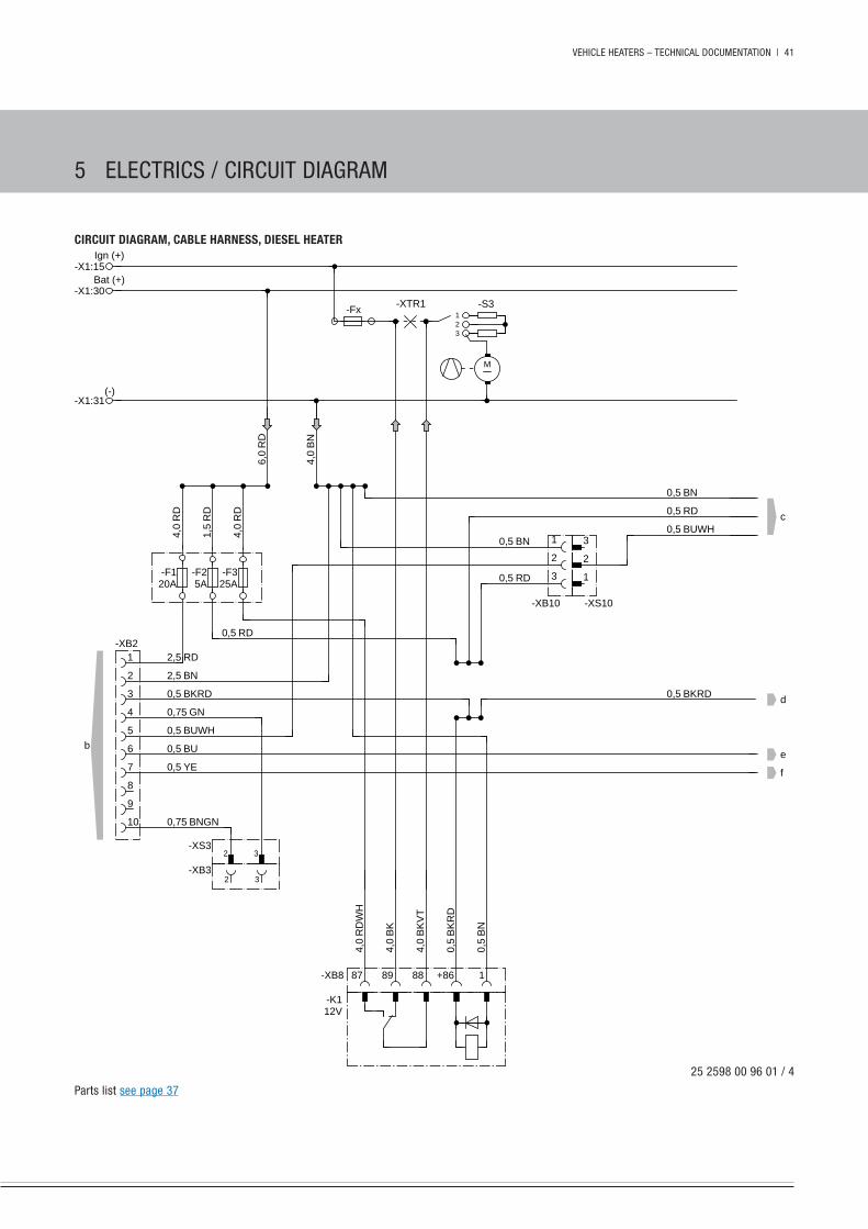
VehiCLe heATeRs – TeChniCAL DOCuMenTATiOn | 41
circuit diagram, cablE harNEss, diEsEl hEatEr
123
-S3-XTR1
M
1
2
3
4
5
6
7
8
9
10
2,5 RD
2,5 BN
0,5 BKRD
0,75 GN
0,5 BUWH
0,5 BU
0,5 YE
-XB2
0,75 BNGN
-XB32 3
2 3-XS3
-K112V
c
d
e
f
-Fx
-X1:30Bat (+)
-X1:31(-)
-X1:15Ign (+)
4,0
RD
1,5
RD
4,0
RD
6,0
RD
-F120A
-F25A
-F325A
-XB10
1
2
3
0,5 BN
0,5 RD
0,5 BUWH
4,0
BN
-XS10
3
2
1
0,5 BN
0,5 RD
0,5 RD
4,0
RD
WH
4,0
BK
4,0
BK
VT
0,5
BK
RD
0,5
BN
+86-XB8 187 89 88
b
0,5 BKRD
25 2598 00 96 01 / 4
parts list see page 37
5 eLeCTRiCs / CiRCuiT DiAgRAM

42 | VehiCLe heATeRs – TeChniCAL DOCuMenTATiOn
Eu dEclaratioN of coNformity
The manufacturer:
eberspächer Climate Control systems gmbh & Co. kg
Address:
eberspächerstraße 24
D-73730 esslingen
herewith declares that the following product:
product name Vehicle heaterType hydronic ii
Version b 4 s / b 5 s
d 4 s / d 5 s
E 4 s
b 4 sc / b 5 sc
d 4 sc / d 5 sc
fulfils the requirements of the following eC Directives:
a) heating systems directive 2001/56/eC,
Revision status 2006/119/eC
b) Radio interference (eMC) of vehicles 72/245/eeC,
Revision status 2009/19/eC
c) heater control eCe-R 122,
Revision status 00
d) eMC of vehicles eCe-R 10,
Revision status 03
The following eC Directives and un regulations have been used to as-
sess the product: 2001/56/eC; 72/245/eeC; eCe-R 122; eCe-R 10
cErtificatioNs
The high quality of eberspächer's products is the key to our success.
To guarantee this quality, we have organised all work processes in the
company along the lines of quality management (QM). even so, we
still pursue a large number of activities for continuous improvement
of product quality in order to keep pace with the similarly constantly
growing requirements made by our customers.
All the steps necessary for quality assurance are stipulated in interna-
tional standards.
This quality is to be considered in a total sense. it affects products, pro-
cedures and customer / supplier relationships.
Officially approved public experts assess the system and the corre-
sponding certification company awards a certificate.
eberspächer Climate Control systems gmbh & Co. kg has already
qualified for the following standards:
quality maNagEmENt iN accordaNcE with
EN iso 9001:2000 aNd iso/ts 16949:1999
ENViroNmENtal maNagEmENt systEm iN accordaNcE with
EN iso 14001:1996
disposal
DispOsAL OF MATeRiALs
Old devices, defect components and packaging material can all be
separated and sorted into pure-grade factions so that all parts can be
disposed of as required in an environment-friendly manner recycled
where applicable.
electric motors, control boxes and sensors (e.g. temperature sensors)
are deemed to be “electronic scrap”.
DisMAnTLing The heATeR
The heater is dismantled according to the repair stages in the current
troubleshooting / repair instructions.
pACkAging
The packaging of the heater can be kept in case it has to be sent back.
6 enViROnMenT

VehiCLe heATeRs – TeChniCAL DOCuMenTATiOn | 43
list of abbrEViatioNs
adr
european Agreement concerning the international Carriage of Danger-
ous goods by Road.
EcE rEgulatioN
internationally agreed, uniform technical specifications for vehicles,
parts and equipment of motor vehicles.
Emc dirEctiVEs
electromagnetic compatibility.
E85 EthaNol fuEl
petrol containing 85 % ethanol.
famE
Biodiesel to en 14214.
jE partNEr
eberspächer partner.
7 seRViCe
iNdEx
a
Accident prevention 6
ADR 43
Assignment of -xs2 connector 37
b
B 5 sC assembly drawing 23
Battery voltage 12
“Blower” cover 28
c
Cable colours 37
Certifications 42
Check 12
Check flame sensor 34
Check overheating sensor 31
Check the surface sensor 31
Circuit diagram, cable harness, diesel heater 41
Circuit diagram, cable harness, petrol heater 39
Circuit diagram, diesel heater 40
Circuit diagram, petrol heater 38
Comments 17
Connector, control box 25
Connector pin assignment 25
Contents 2 – 4
Control and safety devices 9
Control units 12
Cover, “electric motor” 32
Cutaway view of the hydronic ii Comfort B 5 sC 7
Cutaway view of the hydronic ii Comfort D 5 sC 8
d
D 5 sC assembly drawing 24
Delete fault memory 14
Diagnostics tool 9
Dismantle control box 29
Dismantle glow plug 35
Dismantle the heater 26
Dismantling the heater 42
Disposal 42
E
e85 43
easystart Call 9
easystart Remote+ 9
easystart Remote + radio remote control 9
easystart select 9
easystart select vehicle workshop menu 16
easystart Timer 9
eCe regulation 43
eDiTh Basic 9
electrical components 12
electrics 37
eMC directives 43
eMeRgenCy OFF 6
emergency shutdown 6
enquire / delete fault memory 15
environmental management system 42
eu Declaration of Conformity 42
evaluation 36
external diagnostics system 12
f
FAMe 43
Fault code display 17
Fault description 17
Fault diagnosis 13, 15
Fault memory 15
Functional check 6
Functional description 9
Function and operation 7

44 | VehiCLe heATeRs – TeChniCAL DOCuMenTATiOn
7 seRViCe
g
graphite grommet 35
guarantee 6
h
heater circuit diagram 37
heater wiring 37
heating at high altitudes 9
heating mode 9
holder, metering pump 29
i
initial commissioning 6
introduction 5
isO/Ts 16949:1999 42
j
Je partner 43
l
Liability claim 6
Locking the control box 12
m
Measure blower speed 33
Measurement 36
Measurement / evaluation 36
Measurement with eDiTh Basic 36
Measurement without eDiTh Basic 36
o
Overheating 12
Overheating sensor 29, 30
p
packaging 42
parking heater mode 9
parts list, circuit diagram 37
picture symbols 5
preparation 36
q
Quality management 42
r
Radio remote control 9
Release tool 22
Remedial action 17
Remove cover 26
Remove flame sensor 34
Remove the metering pump 27
Remove the water connection socket 27
Remove the water pump 26
Repair instructions 22
Repair steps 25
s
safety information 6, 22, 37
safety instructions for installation 6
spare parts list 5
special tool 22
start attempts 12
surface sensor 30
switching on 9
t
Table of values 31, 34
Technical data of the hydronic ii Comfort B 5 sC 10
Technical data of the hydronic ii Comfort D 5 sC 11
Technical description 5
Testing equipment 12
Timer 9
Troubleshooting 12
V
Voltage supply 12
w
Workshop menu 16
symbolE
-xs2 connector 25


headquarters:
eberspächer Climate Control systems
gmbh & Co. kg
eberspächerstraße 24
73730 esslingen
hotline: 0800 1234300
Fax hotline: 01805 262624
www.eberspaecher.com 25 2
598
95 2
6 57
11
.201
3 su
bjec
t to
chan
ge w
ithou
t not
ice
© e
bers
päch
er C
limat
e Co
ntro
l sys
tem
s gm
bh &
Co.
kg