n4ce lite fact sheet - opti-cal survey equipment · • client project templates with defaults ......
TRANSCRIPT

n4ce Lite builds on the foundations of n4ce Survey module, which has a complete suite of survey processing, traverse adjustment tools and I/O facilities. However, n4ce Lite has added functionality including graphics based CAD editing, Feature editing, DTM editing, Areas and Volumes, Sections and 3D rendered graphic views.
n4ce Lite
AiC Ltd. reserve the right to change the specifications without notice. 1
Applications in CADD
n4ce Lite Fact Sheet
The n4ce Lite module includes the following:
As n4ce Survey plus:
• Unrestricted Undo/Redo• Soft Save Backups• Copy, Cut and Paste• Dynamic Code Table• Fully Layered Graphics Views• Roller Ball Zoom and Query functions• Last View Stored• Hot Key Interaction• User Defined Icon Bars• Client Project Templates with Defaults• CAD Editing Tools, including:- Changing Attributes- Symbol Library and Editor- Pick, Lock & Draw Modes- Query and Dimensions- Points, Lines, Rectangles, Circles, Text etc.• Multiple Windows with Ripple through• Spreadsheet Style Feature Editor• Graphics Editing Tools• Backcloths – for as built comparisons• CAD - XYZ Data Extraction From Backcloths
• Free Station - Resection calculations• Stored Helmert Coordinate Transformation - applied to Stations, Models and CAD
• Station Tables• Undefined Features – Recode and Define• Insert Points – Chain and Offset etc.• Feature Create and Delete• DTM Creation with Break Line recognition• DTM Editor with Delete, Switch and Insert• Curve Fitted Contours and Annotation• DTM Groups – with depths• DTM Areas and Volumes, using Groups• Surface to Surface Comparisons• Isopachytes Models• Long Sections through Multiple Surfaces• Cross Sections• Dynamic updated 3D Rendered Models• Plot Generator, with Standard Templates• Plotting Raster Imagery – JPG etc.• I/O to AutoCADTM (DXF), MX(GENIO) and general XYZ user defined filters.• OS Landline and MastermapTM Imports
Multiple Views, including Spreadsheet and Graphics Based Editing
Dynamically Updates
The Project Manager controls Different Data Types through the Project Tree
Graphics Editor

Applications in CADD
n4ce Lite Factsheet
Project ManagerThe Project Manager controls data that is being used or created in n4ce. A heading on the Tree identifies data type, which can be Survey Stations, Observations, Coordinates, Elevations, CAD, Models , Sections or Drawings .
Multiple sets of data can be stored and various data files imported into n4ce, including AiC’s own format files, MXTM (MOSS) GENIO and AutoCAD TM DXF.
AiC Ltd. reserve the right to change the specifications without notice. 2
Survey layering can be Overridden with Object Layering. This supplement enables users to turn on/off objects like point markers, height text, line features, shapes etc, irrespective of which survey layer they may fall on. This is particularly useful when plotting Grid Lines and isolating items drawn on the Dedicated CAD Backcloth such as Curve fitted Contours and Station Tables.
Note. Access to the Dedicated CAD Backcloth is restricted in the n4ce Lite edition.
Project Manager -Tree
CAD Editor showing Survey and OS Backcloths (green)
Layering and Default SettingsVarious Settings are used in n4ce. These generally control what is seen in graphics. Projects are stored with their own defaults in an SDB file. A Reload option allows the recall of Master Defaults.
User defined Layers contain their own defaults.
Default SettingsLayer Override
Each user-defined layer contains default settings as shown above. Windows Text Fonts and user defined Line Styles are available.
CAD ModellingCAD is a very important part of n4ce and is used to supplement the survey, not to replace it. CAD can be used to sketch detail, provide notes or plot detail such as Symbols and is used in Sections and Drawings.
n4ce CAD supports the normal drawing functions with unlimited Layers , 256 Colours , user definable Line Style and Text Styles (Windows fonts).
Picking (Element & Rectangle), Locking (Free, End, Mid Near, Intersect, Centre, Point) and Drawing (Relative, Polar, Bearing, World, Axis Lock) modes.
CAD Backcloths are used to generate Co-ordinate Points from individual elements or from grouped elements.
These generated coordinates can be uploaded toa Total Station for setting out or used to create a DTM for volume calculations, sections and contours.
CAD Backcloths can also be used to compare the Design (CAD) with As Built (Surveys), using Dimensions .
Applications in CADD
n4ce Lite Factsheet
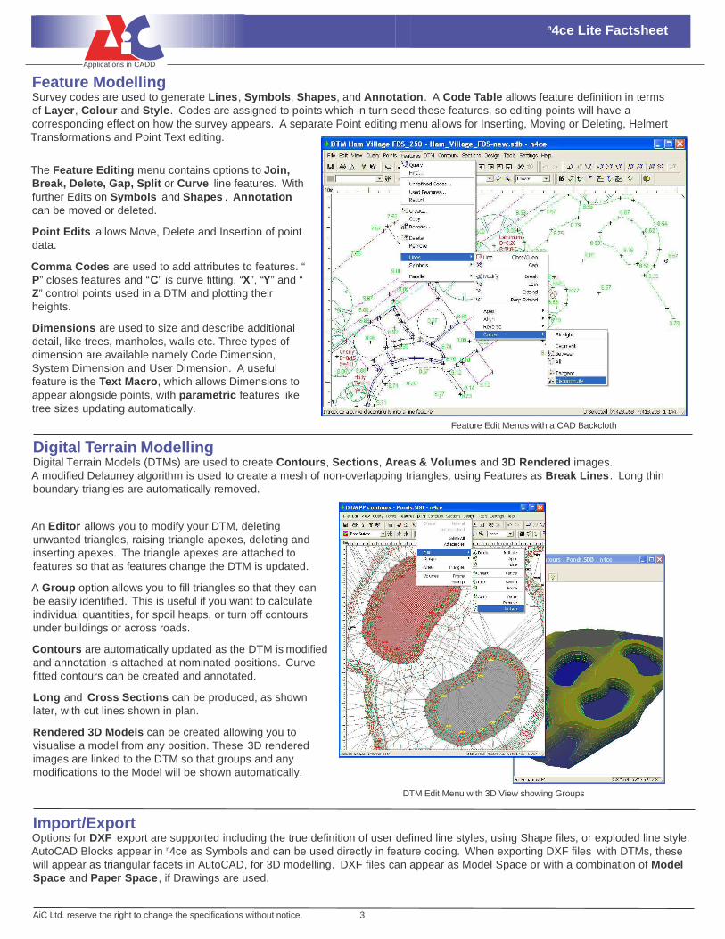
Feature ModellingSurvey codes are used to generate Lines , Symbols, Shapes, and Annotation . A Code Table allows feature definition in termsof Layer , Colour and Style . Codes are assigned to points which in turn seed these features, so editing points will have a corresponding effect on how the survey appears. A separate Point editing menu allows for Inserting, Moving or Deleting, Helmert Transformations and Point Text editing.
AiC Ltd. reserve the right to change the specifications without notice. 3
Digital Terrain ModellingDigital Terrain Models (DTMs) are used to create Contours, Sections, Areas & Volumes and 3D Rendered images.A modified Delauney algorithm is used to create a mesh of non-overlapping triangles, using Features as Break Lines . Long thin boundary triangles are automatically removed.
Feature Edit Menus with a CAD Backcloth
DTM Edit Menu with 3D View showing Groups
The Feature Editing menu contains options to Join, Break, Delete, Gap, Split or Curve line features. With further Edits on Symbols and Shapes . Annotation can be moved or deleted.
Point Edits allows Move, Delete and Insertion of point data.
Comma Codes are used to add attributes to features. “ P” closes features and “ C” is curve fitting. “ X”, “ Y” and “ Z” control points used in a DTM and plotting their heights.
Dimensions are used to size and describe additional detail, like trees, manholes, walls etc. Three types of dimension are available namely Code Dimension, System Dimension and User Dimension. A useful feature is the Text Macro, which allows Dimensions to appear alongside points, with parametric features like tree sizes updating automatically.
An Editor allows you to modify your DTM, deleting unwanted triangles, raising triangle apexes, deleting and inserting apexes. The triangle apexes are attached to features so that as features change the DTM is updated.
A Group option allows you to fill triangles so that they can be easily identified. This is useful if you want to calculate individual quantities, for spoil heaps, or turn off contours under buildings or across roads.
Contours are automatically updated as the DTM is modified and annotation is attached at nominated positions. Curve fitted contours can be created and annotated.
Long and Cross Sections can be produced, as shown later, with cut lines shown in plan.
Rendered 3D Models can be created allowing you to visualise a model from any position. These 3D rendered images are linked to the DTM so that groups and any modifications to the Model will be shown automatically.
Import/ExportOptions for DXF export are supported including the true definition of user defined line styles, using Shape files, or exploded line style. AutoCAD Blocks appear in n4ce as Symbols and can be used directly in feature coding. When exporting DXF files with DTMs, these will appear as triangular facets in AutoCAD, for 3D modelling. DXF files can appear as Model Space or with a combination of Model Space and Paper Space , if Drawings are used.

Applications in CADD
n4ce Lite Factsheet
AiC Ltd. reserve the right to change the specifications without notice. 4
t: +44 (0) 1509 504501 f: +44 (0) 1509 600079
e: [email protected] www.appsincadd.co.ukApplications in CADD
Applications in CADD Ltd. 21 Britannia Street, Shepshed
Leicestershire LE12 9AE United Kingdom
DrawingsThe quality of your work will be measured by your presentations. Plots can be created in most parts of the Project, but it is with Drawings that the finishing touches can be added, including pre- defined Notes and Title Boxes .
n4ce uses the concept of a drawing sheet with windows onto the project. Models and any CAD data will appear in these Viewports at their own scale, with Sections and final detail being plotted and the Drawing sheet, which has a scale of 1:1. The former is called Model Space , the latter Paper Space .
Pre-defined sheets, called Drawing Templates , can be created with Title Boxes, User Notes, Key Plans etc. Raster images or Photographs in various formats can be included in Drawings, as shown opposite.
Final Drawing Presentation using Viewports
Plotted Sections with Automatic Filtering and Flipping of Drop Lines
Section Plot Parameters
Long Section Dialog Box
SectionsLong Sections can be taken passing through single or multiple Models and/or Features . The cut line can be Sketched, taken from Points or Features or from pre-defined Coordinates.
Alternatively Cross-Sections can be generated at defined change intervals covering and left and right offsets. The centre line can be taken off an existing feature or simply sketched out. A special multi-section plotting option is provided or alternatively you may plot these individually.
Sections will initially appear in a section viewer. Colours, Line styles and scales can be changed prior to saving a section of the project tree before final presentation.
Sections can be plotted in either Model or Paper Space for final presentations. Drop lines can be filtered to remove overlapping text. Single or multiple surface profiles can be created.
The Section Plot Defaults dialog controls much of what will be plotted, practically everything you see is user definable including table headings.
The Dialog box shown allows you to set the plotting options you require. Also note that sections can be taken through DTM and/or Feature Strings.