na vi ga ti on-receiver rn 3320 - (01 ) / - (02) vor/loc ... · 1.3 va riants sur vey 1-2 ... supp...
TRANSCRIPT

In stal la ti on and Ope ra ti on
Ma nu al DV 60603.03Is sue 1 July 1997Chan ge 1 Au gust 1998
Becker Flugfunkwerk GmbH • Baden Airpark • 77836 Rheinmünster • Germany
Telephone +49 (0) 7229 / 305-0 • Fax +49 (0) 7229 / 305-217
hppt://www.becker-avionics.de • Email : info@be cker-avionics.de
Na vi ga ti on-Receiver
RN 3320 - (01 ) / - (02)VOR/LOC and GS
RN 3330 - (01) / - (02)VOR/LOC

FIRST IS SUE AND CHAN GES
Is sue . . . . . 1 . . . . . July 1997Chan ge . . . . 1 . . . . Au gust 1998
LIST OF EF FEC TI VE PA GES
Page No.: Date : Page No.: Date :
Tit le
1-I - 1-II1-1 - 1-10
2-I - 2-II2-1 - 2-22-32-4 - 2-62-7 - 2-10
08/98
07/9707/97
08/9807/9708/9807/9708/98
© 1998 by Becker Flugfunkwerk,
All rights reserved
Tab le of con tents
Sec ti on 1 GE NE RAL IN FOR MA TI ON Page
1.1 In tro duc ti on 1-1
1.2 Pur po se of equip ment 1-1
1.3 Va riants sur vey 1-2
1.4 Ge ne ral des crip ti on 1-2
1.5 Tech ni cal Data 1-4
1.5.1 Ge ne ral Data 1-4
1.5.2 VOR/LOC re cei ver 1-4
1.5.3 VOR/LOC sys tem functions 1-5
1.5.4 GS re cei ver and functions in the RN 3320 - (01) / - (02) 1-6
1.5.5 In di ca tors 1-6
1.6 Soft wa re 1-6
1.7 Ra tings and air wort hi ness spe ci fi ca tions 1-7
1.8 En vi ron men tal Qua li fi ca ti on Form 1-8
1.9 Ac ces so ries (not con tai ned in the sco pe of de li very) 1-9
RN 3320 - ( ) / RN 3330 - ( )
DV 60603.03/.04 Is sue 07/97 Page 1-I
Blank
RN 3320 - ( ) / RN 3330 - ( )
Page 1-II DV 60603.03/.04 Is sue 07/97

Sec ti on 1 GE NE RAL IN FOR MA TI ON
1.1 In tro duc ti on
The RN 3320 - ( ) / RN 3330 - ( ) re mo te-control na vi ga ti on re cei vers are des cri bed in the fol lo wing ma -nu als. The se na vi ga ti on re cei vers are con trol led by a CU 5301 - ( ) con trol unit (or equal).
The ma nu als DV 60603.03 “In stal la ti on and Ope ra ti on” and DV 60603.04 “Main ten an ce and Re pair”con tain the fol lo wing sec tions :
Sec ti on DV 60603.03 DV 60603.04
1 Ge ne ral In for ma ti on X X
2 In stal la ti on X X
3 Ope ra ti on
4 Theo ry of Ope ra ti on X
5 Main ten an ce and Re pair X
6 Il lu stra ted Parts List X
7 Mo di fi ca ti on and Chan ges X
8 Cir cuit Dia grams X
1.2 Pur po se of equip ment
The na vi ga ti on re cei ver RN 3320 - (01) is de sig ned to re cei ve and con vert VOR and LOC sig nals on200 chan nels in the fre quen cy ran ge bet ween 108.00 MHz and 117.95 MHz.
The na vi ga ti on re cei ver RN 3320 - (02) is de sig ned to re cei ve VOR and LOC sig nals on 200 chan nelsin the fre quen cy ran ge bet ween 108.00 MHz and 117.95 MHz. It supp lies the NAV com po si te sig nal toan ex ter nal VOR/LOC con ver ter. Both na vi ga ti on re cei ver RN 3320 - (01) / -(2) in clu det a gli des lo pe re -cei ver. The gli des lo pe re cei ver is de sig ned to re cei ve and con vert GS sig nals on 40 chan nels in the fre -quen cy ran ge bet ween 108.00 MHz and 117.95 MHz.
RN 3320 - ( ) / RN 3330 - ( )
DV 6063.03/.04 Issue 06/97 Page 1-1

The na vi ga ti on re cei ver RN 3330 - (01) is de sig ned to re cei ve and con vert VOR and LOC sig nals on200 chan nels in the fre quen cy ran ge bet ween 108.00 MHz and 117.95 MHz.
The na vi ga ti on re cei ver RN 3330 - (02) is de sig ned to re cei ve VOR and LOC sig nals on 200 chan nelsin the fre quen cy ran ge bet ween 108.00 MHz and 117.95 MHz. It supp lies the NAV-composite sig nal toan ex ter nal VOR/LOC con ver ter.
1.3 Va riants sur vey
The dif fe rent va riants of the RN 3320 - ( ) / RN 3330 - ( ) na vi ga ti on re cei ver are lis ted in the fol lo wingtab le. They dif fer ex ter nal ly only in the num ber of con nec tors and an ten na so cket. The di men sions are the same for all va riants.
Part-No.: Iden ti fy ing cha rac te ris tics Ar ti cle - No.:
RN 3320 - (01) Na vi ga ti on re cei ver with VOR/LOC and GS functions and
con vert
0505.706-911
RN 3320 - (02) Na vi ga ti on re cei ver with VOR/LOC functi on wit hout con -
vert (NAV com po si te out put) and GS functions with con -
vert
0506.141-911
RN 3330 - (01) Na vi ga ti on re cei ver with VOR/LOC functions and con vert 0506.151-911
RN 3330 - (02) Na vi ga ti on re cei ver with VOR/LOC functions wit hout con -
vert (NAV com po si te out put))
0506.168-911
1.4 Ge ne ral des crip ti on
The na vi ga ti on re cei ver is de sig ned for in stal la ti on in the avio nics com part ment.
The fol lo wing con nec tors are moun ted on the con nec ti on side of the unit.
l The BNC an ten na so cket for the VOR/LOC-receiver.
l The TNC an ten na so cket for the GS-receiver.
l The 15-pole D-subminiature con nec tor (fe ma le) for the out puts of the VOR/LOC con -ver ter board (in the RN 3320 - (01) or RN 3330 - (01) only).
l The 9-pole D-subminiature con nec tor (fe ma le) for the out puts/in puts of the RS 422in ter fa ce.
l The 25-pole D-subminiature (male) equip ment con nec tor.
RN 3320 - ( ) / RN 3330 - ( )
Page 1-2 DV 6063.03/.04 Issue 06/97
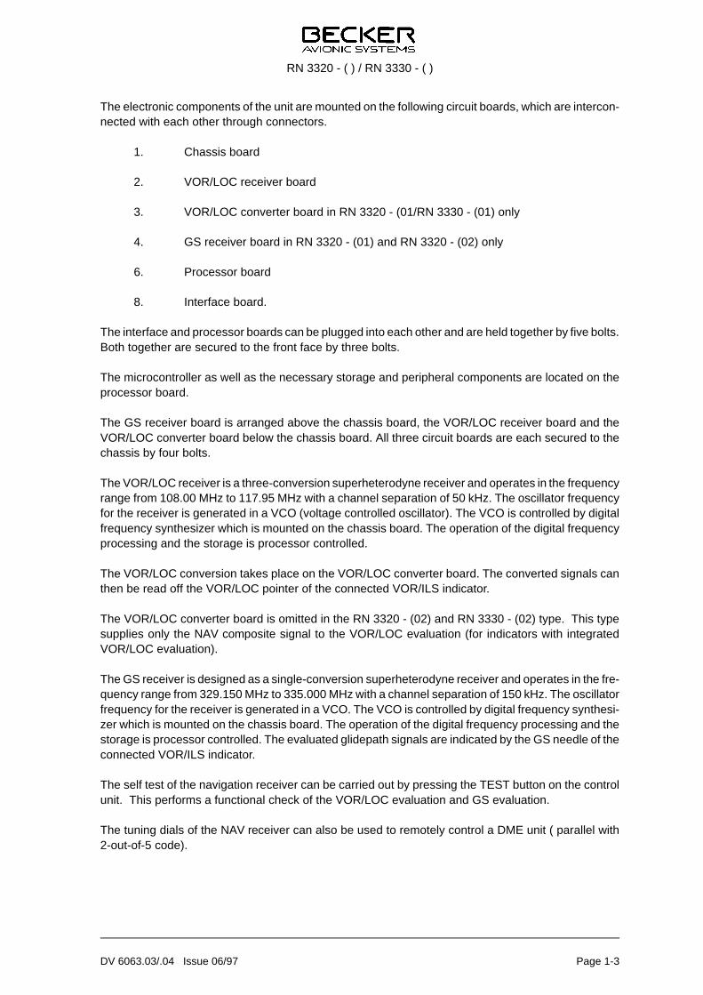
The elec tro nic com po nents of the unit are moun ted on the fol lo wing cir cuit bo ards, which are in ter con -nec ted with each ot her through con nec tors.
1. Chas sis board
2. VOR/LOC re cei ver board
3. VOR/LOC con ver ter board in RN 3320 - (01/RN 3330 - (01) only
4. GS re cei ver board in RN 3320 - (01) and RN 3320 - (02) only
6. Pro ces sor board
8. In ter fa ce board.
The in ter fa ce and pro ces sor bo ards can be plug ged into each ot her and are held to get her by five bolts. Both to get her are se cu red to the front face by three bolts.
The mi cro con trol ler as well as the ne ces sa ry sto ra ge and pe ri phe ral com po nents are lo ca ted on thepro ces sor board.
The GS re cei ver board is ar ran ged abo ve the chas sis board, the VOR/LOC re cei ver board and theVOR/LOC con ver ter board be low the chas sis board. All three cir cuit bo ards are each se cu red to thechas sis by four bolts.
The VOR/LOC re cei ver is a three-conversion su per he te ro dy ne re cei ver and ope ra tes in the fre quen cyran ge from 108.00 MHz to 117.95 MHz with a chan nel se pa ra ti on of 50 kHz. The os cil la tor fre quen cyfor the re cei ver is ge ne ra ted in a VCO (vol ta ge con trol led os cil la tor). The VCO is con trol led by di gi talfre quen cy syn the si zer which is moun ted on the chas sis board. The ope ra ti on of the di gi tal fre quen cypro ces sing and the sto ra ge is pro ces sor con trol led.
The VOR/LOC con ver si on ta kes pla ce on the VOR/LOC con ver ter board. The con ver ted sig nals canthen be read off the VOR/LOC poin ter of the con nec ted VOR/ILS in di ca tor.
The VOR/LOC con ver ter board is omit ted in the RN 3320 - (02) and RN 3330 - (02) type. This typesupp lies only the NAV com po si te sig nal to the VOR/LOC eva lua ti on (for in di ca tors with in te gra tedVOR/LOC eva lua ti on).
The GS re cei ver is de sig ned as a sing le-conversion su per he te ro dy ne re cei ver and ope ra tes in the fre -quen cy ran ge from 329.150 MHz to 335.000 MHz with a chan nel se pa ra ti on of 150 kHz. The os cil la torfre quen cy for the re cei ver is ge ne ra ted in a VCO. The VCO is con trol led by di gi tal fre quen cy syn the si -zer which is moun ted on the chas sis board. The ope ra ti on of the di gi tal fre quen cy pro ces sing and thesto ra ge is pro ces sor con trol led. The eva lua ted gli de path sig nals are in di ca ted by the GS need le of thecon nec ted VOR/ILS in di ca tor.
The self test of the na vi ga ti on re cei ver can be car ried out by pres sing the TEST but ton on the con trolunit. This per forms a functio nal check of the VOR/LOC eva lua ti on and GS eva lua ti on.
The tu ning di als of the NAV re cei ver can also be used to re mo te ly con trol a DME unit ( par al lel with2-out-of-5 code).
RN 3320 - ( ) / RN 3330 - ( )
DV 6063.03/.04 Issue 06/97 Page 1-3
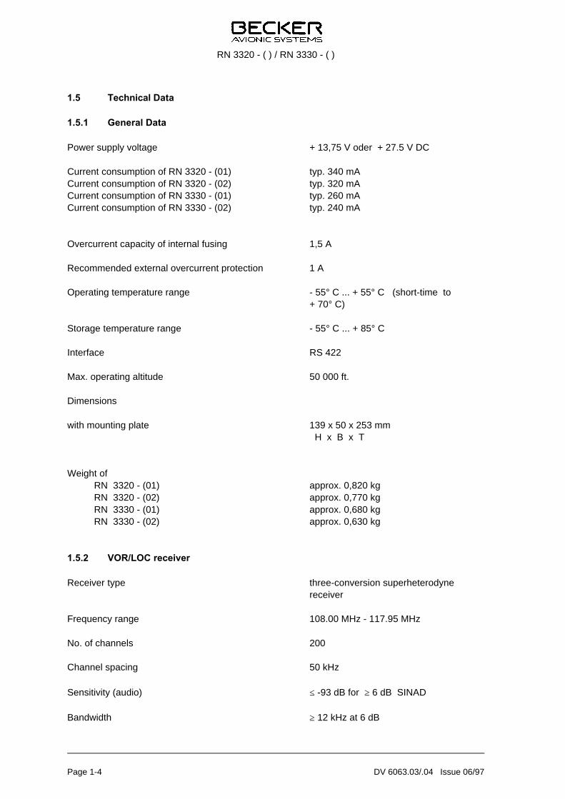
1.5 Tech ni cal Data
1.5.1 General Data
Po wer supp ly vol ta ge + 13,75 V oder + 27.5 V DC
Cur rent con sump ti on of RN 3320 - (01) typ. 340 mA Cur rent con sump ti on of RN 3320 - (02) typ. 320 mA Cur rent con sump ti on of RN 3330 - (01) typ. 260 mA Cur rent con sump ti on of RN 3330 - (02) typ. 240 mA
Over cur rent ca pa ci ty of in ter nal fu sing 1,5 A
Re com men ded ex ter nal over cur rent pro tec ti on 1 A
Ope ra ting tem pe ra tu re ran ge - 55° C ... + 55° C (short-time to + 70° C)
Sto ra ge tem pe ra tu re ran ge - 55° C ... + 85° C
In ter fa ce RS 422
Max. ope ra ting al ti tu de 50 000 ft.
Di men sions
with moun ting pla te 139 x 50 x 253 mm H x B x T
Weight of RN 3320 - (01) ap prox. 0,820 kgRN 3320 - (02) ap prox. 0,770 kgRN 3330 - (01) ap prox. 0,680 kgRN 3330 - (02) ap prox. 0,630 kg
1.5.2 VOR/LOC receiver
Re cei ver type three-conversion su per he te ro dy nere cei ver
Fre quen cy ran ge 108.00 MHz - 117.95 MHz
No. of chan nels 200
Chan nel spa cing 50 kHz
Sen si ti vi ty (au dio) ≤ -93 dB for ≥ 6 dB SI NAD
Band width ≥ 12 kHz at 6 dB
RN 3320 - ( ) / RN 3330 - ( )
Page 1-4 DV 6063.03/.04 Issue 06/97

Se lec ti vi ty ≥ 65 dB at ∆F ≥ ± 50 kHz
AGC ≤ 3 dB from -87 dBm . . . . -10 dBm
Dis tor ti on ≤ 10%
Au dio out put 150 mW at 300 Ω symm.
NAV sig nal (com po si te) 500 mV at 30 Hz, mod = 30%
VOI CE fil ter ≥ 20 dB re duc ti on
DME re mo te con trol par al lel, with 2-out-of-5 codein ac cor dan ce with ARINC 410
1.5.3 VOR/LOC system functions
Sen si ti vi ty ≤ -93 dBm for full di rec ti on sen si ti vi ty
Bea ring er ror un der nor mal con di tions ≤ ± 2°
Bea ring er ror un der all en vi ron men talin flu en ces lis ted in JTSO 2C40cwith 95% pro ba bi li ty ≤ ± 2.7°
Cour se de via ti on for full sca le de flec ti on ± 10°
LOC cen te ring er ror un der all en vi ron men talcon di tions, with 95% pro ba bi li ty ≤ 11% of stan dard de via ti on
RN 3320 - (01) and RN 3330 - (01) only
Re sol ver out put stan dard va lue as per ARINC 407
VOR/LOC need le out put max. of 3 poin ters and/or flagswith 1 kΩ each
VOR/LOC war ning flag out put max. of 3 poin ters and/or flagswith 1 kΩ each
TO/FROM out put max. of 3 poin ters and/or flagswith 1 kΩ each
Au to pi lot out put for VOR cour se trac king and ILS mode
RN 3320 - ( ) / RN 3330 - ( )
DV 6063.03/.04 Issue 06/97 Page 1-5
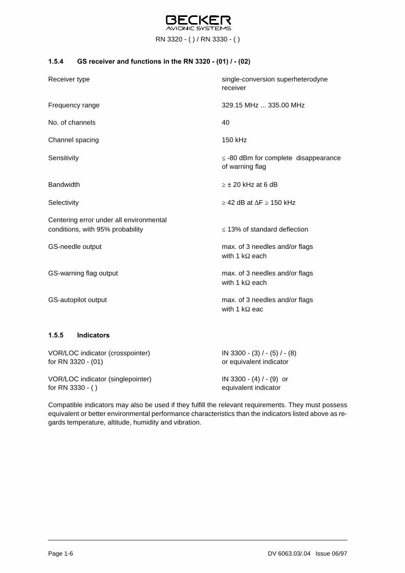
1.5.4 GS receiver and functions in the RN 3320 - (01) / - (02)
Re cei ver type sing le-conversion su per he te ro dy ne re cei ver
Fre quen cy ran ge 329.15 MHz ... 335.00 MHz
No. of chan nels 40
Chan nel spa cing 150 kHz
Sen si ti vi ty ≤ -80 dBm for com ple te dis ap pea ran ce of war ning flag
Band width ≥ ± 20 kHz at 6 dB
Se lec ti vi ty ≥ 42 dB at ∆F ≥ 150 kHz
Cen te ring er ror un der all en vi ron men talcon di tions, with 95% pro ba bi li ty ≤ 13% of stan dard de flec ti on
GS-needle out put max. of 3 need les and/or flagswith 1 kΩ each
GS-warning flag out put max. of 3 need les and/or flagswith 1 kΩ each
GS-autopilot out put max. of 3 need les and/or flagswith 1 kΩ eac
1.5.5 Indicators
VOR/LOC in di ca tor (cros spoin ter) IN 3300 - (3) / - (5) / - (8) for RN 3320 - (01) or equi va lent in di ca tor
VOR/LOC in di ca tor (sing le poin ter) IN 3300 - (4) / - (9) orfor RN 3330 - ( ) equi va lent in di ca tor
Com pa ti ble in di ca tors may also be used if they ful fill the re le vant re qui re ments. They must pos sessequi va lent or bet ter en vi ron men tal per for man ce cha rac te ris tics than the in di ca tors lis ted abo ve as re -gards tem pe ra tu re, al ti tu de, hu mi di ty and vi brat ion.
RN 3320 - ( ) / RN 3330 - ( )
Page 1-6 DV 6063.03/.04 Issue 06/97
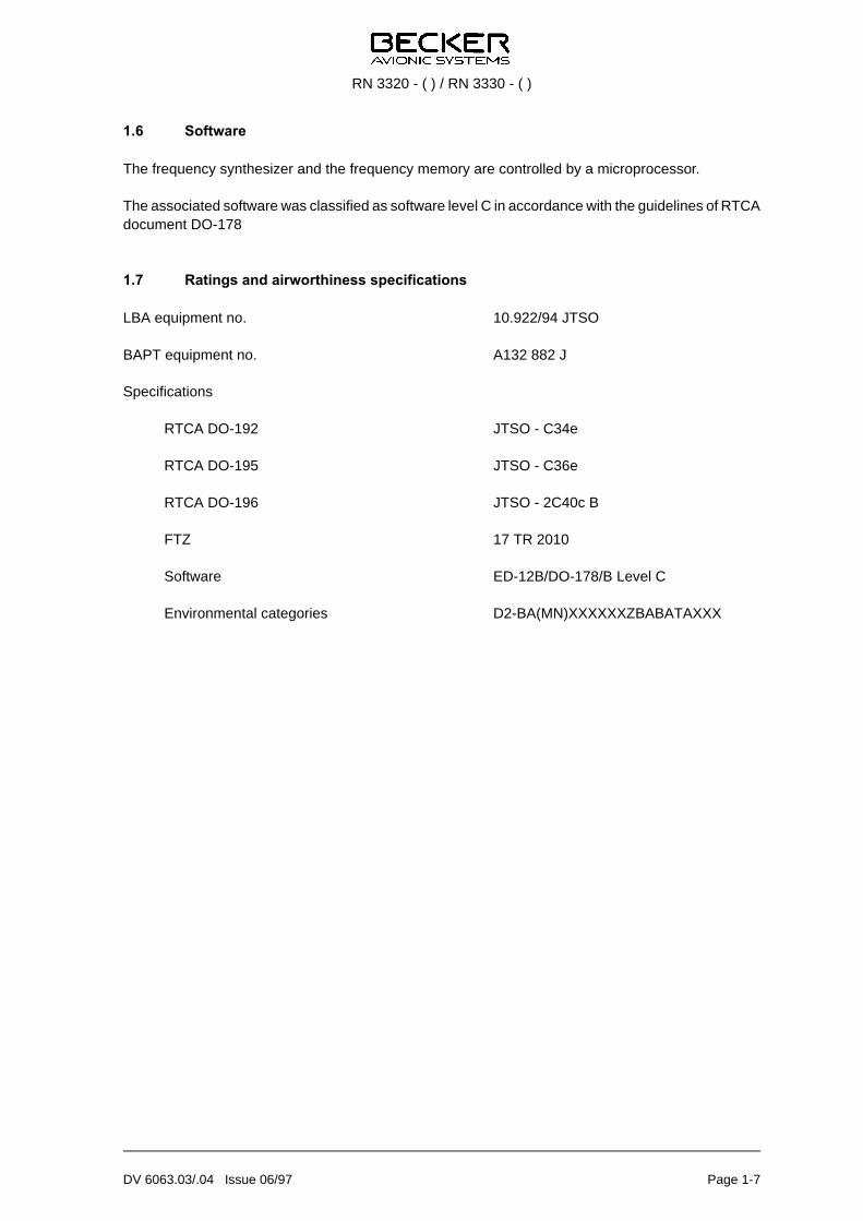
1.6 Soft wa re
The fre quen cy syn the si zer and the fre quen cy me mo ry are con trol led by a mi cro pro ces sor.
The as so cia ted soft wa re was clas si fied as soft wa re le vel C in ac cor dan ce with the gui de li nes of RTCAdo cu ment DO-178
1.7 Ra tings and air wort hi ness spe ci fi ca tions
LBA equip ment no. 10.922/94 JTSO
BAPT equip ment no. A132 882 J
Spe ci fi ca tions
RTCA DO-192 JTSO - C34e
RTCA DO-195 JTSO - C36e
RTCA DO-196 JTSO - 2C40c B
FTZ 17 TR 2010
Soft wa re ED-12B/DO-178/B Le vel C
En vi ron men tal ca te go ries D2-BA(MN)XXXXXXZBA BA TAXXX
RN 3320 - ( ) / RN 3330 - ( )
DV 6063.03/.04 Issue 06/97 Page 1-7
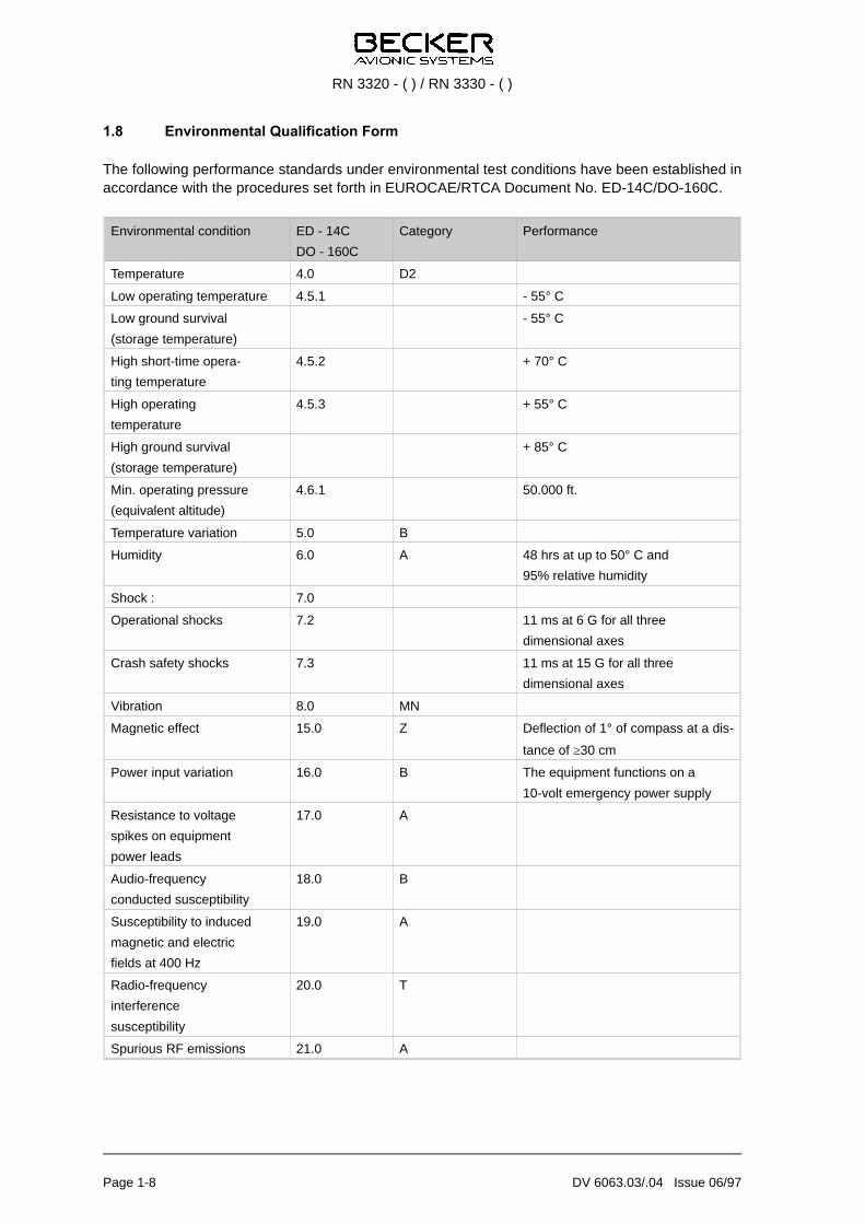
1.8 En vi ron men tal Qua li fi ca ti on Form
The fol lo wing per for man ce stan dards un der en vi ron men tal test con di tions have been estab lis hed inac cor dan ce with the pro ce du res set forth in EU RO CAE/RTCA Do cu ment No. ED-14C/DO-160C.
En vi ron men tal con di ti on ED - 14C
DO - 160C
Ca te go ry Per for man ce
Tem pe ra tu re 4.0 D2
Low ope ra ting tem pe ra tu re 4.5.1 - 55° C
Low ground sur vi val
(sto ra ge tem pe ra tu re)
- 55° C
High short-time ope ra-
ting tem pe ra tu re
4.5.2 + 70° C
High ope ra ting
tem pe ra tu re
4.5.3 + 55° C
High ground sur vi val
(sto ra ge tem pe ra tu re)
+ 85° C
Min. ope ra ting pres su re
(equi va lent al ti tu de)
4.6.1 50.000 ft.
Tem pe ra tu re va ria ti on 5.0 B
Hu mi di ty 6.0 A 48 hrs at up to 50° C and
95% re la ti ve hu mi di ty
Shock : 7.0
Ope ra tio nal shocks 7.2 11 ms at 6 G for all three
di men sio nal axes
Crash sa fe ty shocks 7.3 11 ms at 15 G for all three
di men sio nal axes
Vi brat ion 8.0 MN
Mag ne tic ef fect 15.0 Z De flec ti on of 1° of com pass at a dis -
tan ce of ≥30 cm
Po wer in put va ria ti on 16.0 B The equip ment functions on a
10-volt emer gen cy po wer supp ly
Re sis tan ce to vol ta ge
spi kes on equip ment
po wer le ads
17.0 A
Au dio-frequency
con duc ted sus cep ti bi li ty
18.0 B
Sus cep ti bi li ty to in du ced
mag ne tic and elec tric
fields at 400 Hz
19.0 A
Ra dio-frequency
in ter fe ren ce
sus cep ti bi li ty
20.0 T
Spu ri ous RF emis sions 21.0 A
RN 3320 - ( ) / RN 3330 - ( )
Page 1-8 DV 6063.03/.04 Issue 06/97

1.9 Ac ces so ries (not con tai ned in the sco pe of de li very)
1 Ca ble con nec tor 9-pin male
Crimp ver si on Ar ti cle-No. 0820.970-277orsol de ring ver si on Ar ti cle-No. 0344.699-277Case Ar ti cle-No. 0799.191-277
1 Ca ble con nec tor 15-pin male
Crimp ver si on Ar ti cle-No. 0812.803-277orsol de ring ver si on Ar ti cle-No. 0726.303-277Case Ar ti cle-No. 0774.049-277
1 Ca ble con nec tor 25-pin fe ma le
Crimp ver si on Ar ti cle-No. 0472.921-277orsol de ring ver si on Ar ti cle-No. 0725.021-277Case Ar ti cle-No. 0344.834-2772 set springl Ar ti cle-No. 0725.560-277
1 An ten na con nec tor VOR/LOC, BNC Ar ti cle-No. 0725.706-277
1 An ten na GS, TNC Ar ti cle-No. 0725.900-277 (only for RN 3320 - (01) / - (02))
Hand books
In stal la ti on and Ope ra ti on Ar ti cle-No. 0511.609-071
Main ten an ce and Re pair Ar ti cle-No. 0511.617-071
RN 3320 - ( ) / RN 3330 - ( )
DV 6063.03/.04 Issue 06/97 Page 1-9

Blank
RN 3320 - ( ) / RN 3330 - ( )
Page 1-10 DV 6063.03/.04 Issue 06/97
Tab le of con tents
Sec ti on 2 IN STAL LA TI ON Page
2.1 Ge ne ral 2-1
2.2 Pre-installation check 2-1
2.3 Me cha ni cal in stal la ti on 2-1
2.4 In stal la ti on wi ring 2-1
2.4.1 Con nec ti on of ad di tio nal poin ters or flags 2-2
2.4.2 Con nec ti on of an au to pi lot (VOR/LOC and GS) 2-2
2.4.3 Con nec ti on of VOR/LOC and GS su per flags 2-2
2.4.4 Wi ring for ILS-mode con trol functi on 2-2
2.4.5 Re mo te con trol of a DME unit 2-2
2.4.6 Con nec ti on of in di ca tors of ot her ma kes 2-2
2.4.7 Con nec ti on of the au dio out put 2-3
2.4.8 Asym me tric wi ring of the au dio out put (from se ri al no. 99) 2-3
2.4.9 Asym me tric wi ring of the au dio out put (up wards se ri al no. 100) 2-3
2.5 Post-installation check 2-4
2.5.1 Ge ne ral 2-4
2.5.2 Te sting pro ce du res 2-4
Fig. 2-1 In stal la ti on di men sions for the na vi ga ti on re cei ver 2-6
Fig. 2-2 In stal la ti on wi ring for the na vi ga ti on re cei ver, con trol unit and in di ca tor IN 3300 - (03)2-7
Fig. 2-3 In stal la ti on wi ring for the na vi ga ti on re cei ver, con trol unit and in di ca tor IN 3300 - (4) 2-9
RN 3320 - ( ) / RN 3330 - ( )
DV 60603.03/.04 Is sue 08/98 Page 2-I

Blank
RN 3320 - ( ) / RN 3330 - ( )
Page 2-II DV 60603.03/.04 Is sue 08/98

Sec ti on 2 IN STAL LA TI ON
2.1 Ge ne ral
In stal la ti on of the na vi ga ti on re cei ver va ries ac cor ding to air craft and equip ment de sign. It is the re fo reonly pos si ble to pro vi de ge ne ral gui de li nes in this sec ti on.
2.2 Pre-installation check
Pri or to in stal ling the na vi ga ti on re cei ver in an air craft, a vi su al in spec ti on should be car ried out to de -ter mi ne whet her any da ma ge has been cau sed du ring trans port. The fol lo wing de fects should be che -cked for :
1. Soi ling, dents, scrat ches, rust, bro ken fa ste ners, chip ped paint coat on hou sing or hou sing parts.
2. Soi ling, bent or cra cked pins, cra cked plug or jack in serts.
3. Mis sing screws.
2.3 Me cha ni cal in stal la ti on
The na vi ga ti on re cei ver is de sig ned for in stal la ti on in an avio nics com part ment. To do this, the moun -ting pla te must first be se cu red to an ap pro pria te point in the avio nics com part ment using five bolts. The in stal la ti on di men sions are gi ven in Fig. 2-1. The na vi ga ti on re cei ver is then pus hed into the moun tingpla te and lo cked in pla ce by two quick-release bolts.
2.4 In stal la ti on wi ring
The In stal la ti on wi ring dia gram of the RN 3320 - ( ) and RN 3330 - ( ) na vi ga ti on re cei ver with the CU 5301 - ( ) con trol unit is shown in Fig. 2-2 and 2-3.
CAUTION
No HF ca bles should be tied in to get her with the wi ring of the na vi ga ti on sys tem. The con -nec ting li nes must also not be laid to get her with ca bles car ry ing au dio sig nals or puls ed in -for ma ti on (e.g. IFCS, DME, XPR, sla ved gyro). The same holds for supp ly and con trol li -nes of au to pi lots.
RN 3320 - ( ) / RN 3330 - ( )
DV 60603.03/.04 Issue 06/97 Page 2-1

2.4.1 Connection of additional pointers or flags
It is pos si ble to con nect up to two 1-kW supp le men ta ry in stru ments with VOR/LOC poin ter, VOR/LOCwar ning flag, TO/FROM in di ca ti on and GS poin ter and GS war ning flag to the RN 3320 - (01) / - (02)par al lel to the in di ca tor wit hout al te ring the re cei ver.
2.4.2 Connection of an autopilot (VOR/LOC and GS)
The na vi ga ti on re cei vers are equip ped with out puts for con nec ti on of an au to pi lot. The cor re spon dingpin as signments on P1 are shown in Figs. 2-2 to 2-3 (+ VOR/LOC and - VOR/LOC and, for (+ GS and -GS).
CAUTION
The out puts are loa ded with a DC off set vol ta ge of + 5 V.
2.4.3 Connection of VOR/LOC and GS superflags
If it is wis hed for the con ver ted VOR/LOC and GS sig nals to be fed to the SU PER FLAG in puts of cour se gui dan ce sys tems, then 2 re lays must be in stal led in the wi ring (cf. Fig. 2-2) that are con trol led by theSU PER FLAG CON TROL out puts. Sin ce the swit ching is done by tran sis tors in si de of the na vi ga ti onre cei ver who se open col lec tors feed pin 7 of re cei ver plug J 3 and pin 8 of re cei ver plug J 2, when doingthe wi ring it is vi tal not to ex ceed the cur rent 150 mA at the supp ly vol ta ge 30 V.
NOTE
Ac cor ding to ARINC 478/479, cour se gui dan ce sys tems re qui re 27.5-volt DC sig nals toin di ca te that the con ver ted NAV sig nals are usa ble (re ver sing the war ning flag functi on).
2.4.4 Wiring for ILS-mode control function
The ILS-mode con trol functi on can be used to ope ra te an IFC (In stru ment Flight Con trol) sys tem or si -mi lar sys tems, such as au to ma tic swit ching of an au to pi lot to VOR and ILS mo des. The ILS-mode con -trol fea tu re con sists of the ILS-mode tran sis tor switch, the open col lec tor of which feeds pin 19 or re cei -ver plug P 1. The tran sis tor is off du ring VOR ope ra ti on and on du ring ILS ope ra ti on. When doing thewi ring it is vi tal not to ex ceed the cur rent 150 mA at the supp ly vol ta ge 30 V. If the se con di tions are notful fil led, then an ex ter nal con trol re lay must be in ser ted.
2.4.5 Remote control of a DME unit
The NAV re cei ver is equip ped for the con nec ti on of a re mo te DME unit with par al lel sig nal-transmission in 2-out-of-5 code (cf. in stal la ti on wi ring dia gram, Figs. 2-2 and 2-3).
2.4.6 Connection of indicators of other makes
In di ca tors made by ot her ma nu fac tu rers that are equip ped with a stan dard ARINC re sol ver are di rect lycom pa ti ble with the VOR/LOC con ver ter of the na vi ga ti on re cei ver and may be con nec ted.
RN 3320 - ( ) / RN 3330 - ( )
Page 2-2 DV 60603.03/.04 Issue 06/97
2.4.7 Connection of the audio output
The au dio out put of the na vi ga ti on re cei ver is set to a sym me tri cal au dio out put on de li very. A sym me -tri cal se lec ti on sys tem or he ad set can be con nec ted at P 1 pin 11 Au dio Out (150 mW/300 Ohm) andequip ment con nec tor J 2 pin 9 Au dio Low (ground).
To avoid un wan ted coup ling, this should be as clo se as pos si ble to the se lec tor sys tem.
2.4.8 Asymmetric wiring of the audio output (from serial no. 99)
If ne ces sa ry, the au dio out put can also be chan ged to an asym me tric au dio out put. To chan ge over,jum per Br 1 has to be con nec ted to ground on the chas sis board. The con nec ti on as signments do notchan ge. J 2 pin 9 (Au dio Low) is then con nec ted to the unit ground.
2.4.9 Asymmetric wiring of the audio output (upwards serial no. 100)
Up wards se ri al no. 100 at ten ti on the note in the in ter wi ring dia gram.
RN 3320 - ( ) / RN 3330 - ( )
DV 60603.03/.04 Issue 06/97 Page 2-3

2.5 Post-installation check
2.5.1 General
Af ter the con trol unit, na vi ga ti on re cei ver and the in di ca tor have been in stal led, it is ne ces sa ry to checkthe na vi ga ti on sys tem for pro per functio ning of the equip ment. The pro ce du res des cri bed be low alsoin clu de te sting of the cor re spon ding air craft an ten nas for re li ab le ope ra ti on.
2.5.2 Testing procedures
In ter nal na vi ga ti on re cei ver functions
1. Switch on the na vi ga ti on sys tem at the con trol unit. The last fre quen cies used are shown in the LCdis plays af ter the po wer on re set. The mode se lec ted be fo re po wer off is also ac ti ve. In the chan nelmode it must be pos si ble to sto re the chan nel fre quen cies.
2. Press the TEST but ton. The di gits 188.88 should flash on and off (dis play test). At the same time,the VOR/LOC poin ter of the in di ca tor should swing all the way out and the VOR/LOC war ning flagshould dis ap pe ar. In na vi ga ti on re cei ver RN 3320 - (01) / - (02) the GS poin ter of the in di ca torshould also de flect ful ly and the GS war ning flag should dis ap pe ar.
VOR sys tem functions
1. Con nect the RF out put of the VOR/LOC sig nal ge ne ra tor to a suit ab le VOR an ten na. The dis tan cebet ween the an ten na and the air craft should be ap pro xi ma te ly 20 me ters. Set the stan dard VORtest sig nal to 330° FROM. Set the RF out put at te nua tor to 50 mV, test fre quen cy 114.9 MHz.
2. Set a 114.9 MHz fre quen cy on the con trol unit.
3. Using the OBS dial on the in di ca tor, set a cour se of 330° (up per sca le mar king “ t ”). The ver ti calneed le is cen te red, the VOR/LOC war ning flag dis ap pe ars and the TO/FROM in di ca tor should in di -ca te FROM.
4. Set the VOR AF ge ne ra tor to 150°. The ver ti cal need le should not de via te from cen ter po si ti on bymore than ± 2° and the TO/FROM in di ca tor should in di ca te TO.
5. Using the OBS dial, vary the cour se bea ring by 10°. The ver ti cal need le should in di ca te full de flec ti -on (5 points).
LOC sys tem functions
1. Set the VOR/LOC sig nal ge ne ra tor to 110.9 MHz and 50 mV with the stan dard LOC cen te ring sig -nal.
2. Set a 110.9 MHz fre quen cy on the con trol unit. The ver ti cal need le should be cen te red and theVOR/LOC war ning flag should dis ap pe ar.
3. When the trans mit ter is set to stan dard LOC de via ti on sig nal, the ver ti cal need le should de flect3 points in the cor re spon ding di rec ti on.
RN 3320 - ( ) / RN 3330 - ( )
Page 2-4 DV 60603.03/.04 Issue 06/97

GS sys tem functions in RN 3320 - (01) / - (02)
1. Con nect the GS sig nal ge ne ra tor to a suit ab le GS an ten na.
2. Set a 108.95 MHz fre quen cy on the con trol unit (this cor re sponds to GS fre quen cy 329.15 MHz).
3. Set the sig nal ge ne ra tor to 329.15 MHz and RF out put le vel of 50 mV. Set the stan dard gli des lo pecen te ring sig nal. The ho ri zon tal need le on the in di ca tor should re main cen te red and the GS-flagshould re main out of sight.
4. Set the GS-deviation sig nal for “down”. The ho ri zon tal need le should de flect down whi le the GS-flag stays out of sight.
5. Set the GS-deviation sig nal for “up”. The ho ri zon tal need le should de flect up whi le the GS-flag stays out of sight.
RN 3320 - ( ) / RN 3330 - ( )
DV 60603.03/.04 Issue 06/97 Page 2-5

Fig. 2-1 In stal la ti on di men sions for the na vi ga ti on re cei ver
RN 3320 - ( ) / RN 3330 - ( )
Page 2-6 DV 60603.03/.04 Issue 06/97
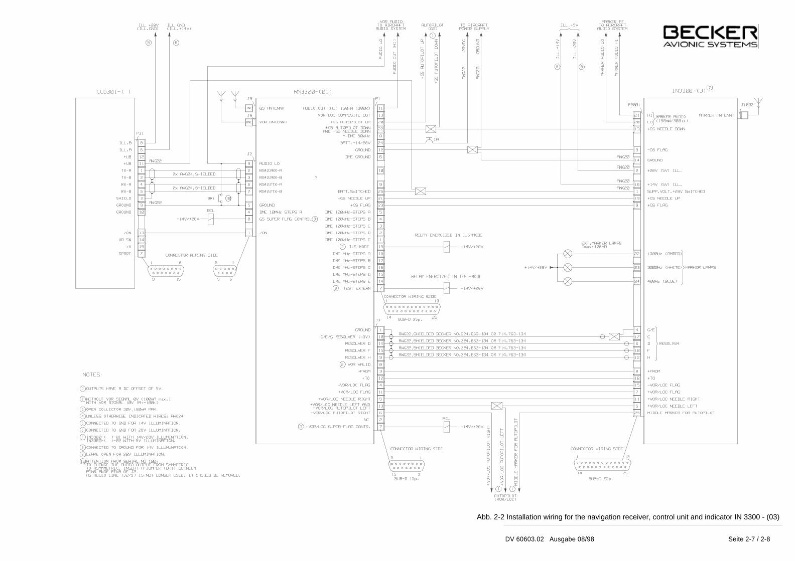
Abb. 2-2 Installation wiring for the navigation receiver, control unit and indicator IN 3300 - (03)
Seite 2-7 / 2-8DV 60603.02 Ausgabe 08/98

DV 60603.03 / 04 Issue 08/98 Page 2-9 / 2-10
Fig. 2-2 Installation wiring for the navigation receiver, control unit and indicator IN 3300 - (4)