name and address of certificate holder: performance...
TRANSCRIPT

Precast Large
Concrete
Panel System
User should check the
validity of the Certificate by contacting Member
Secretary, BMBA at
BMTPC or the Holder of
this Certificate.
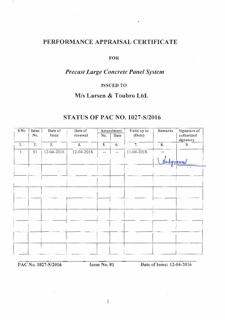
Name and Address of Certificate Holder:
M/s Larsen & Toubro Ltd.
Landmark A, 5th Floor,
Suren Road, Off Andheri Kurla
Road, Andheri East,
Mumbai – 400093
Performance Appraisal
Certificate No.
PAC No 1027-S/2016
Issue No. 01
Date of Issue: 12.04.2016
Building Materials & Technology Promotion Council Ministry of Housing & Urban Poverty Alleviation
Government of India
Core 5A, First Floor, India Habitat Centre,
Lodhi Road, New Delhi – 110 003 Tel: +91-11-2463 8096, 2463 8097; Fax: +91-11-2464 2849
E-mail: [email protected] Web Site: http://www.bmtpc.org

2
CONTENTS
PART 1 CERTIFICATION…………………………………………………………………………….. 3
1.1 Certificate Holder ……………………………………………………………………………………. 3
1.2 Description of System ……………………………………………………………………………….. 3
1.3 Type of Precast Elements…………………………………………………………………………….. 3
1.4 Installation ………………………………………………………………………………………….... 6
1.5 Design Considerations………………………………………………………………………………. 10
1.6 Machinery……………………………………………………………………………………………. 14
1.7 Basis of Assessment …………………………………………………………………………………. 14
1.8 Uses of the System …………………………………………………………………………………… 15
1.9 Conditions of Certification …………………………………………………………………………... 16
1.10 Certification ………………………………………………………………………………………… 17
PART 2 CERTIFICATE HOLDER’S TECHNICAL SPECIFICATION………………………….. 17
2.1 General……………………………………………………………………………………………….. 17
2.2 Specifications of the System……………………. ………………………………………………….. 17
2.3 Tolerances …………………………………………………………………………………………… 18
2.4 Implementation ……………………………………………………………………………………… 26
2.5 Inspection & Testing ………………………………………………………………………………… 30
2.6 Good Practices for Installation & Maintenance …………………………………………………….. 31
2.7 Maintenance requirements ………………………………………………………………………….. 31
2.8 Skills/ training needed for installation ………………………………………………………………. 31
2.9 Guarantees/Warrantees provided by PAC Holder…………………………………………………… 31
2.10 Responsibility ……………………………………………………………………………………… 31
PART 3 BASIS OF ASSESSMENT AND BRIEF DESCRIPTION OF ASSESSMENT
PROCEDURE …………………………………………………………………………………………..
31
3.1 Assessment …………………………………………………………………………………………... 31
3.2 Site Inspection ………………………………………………………………………………………. 32
3.3 Approvals Obtained ………………………………………………………………………………….. 32
3.4 Execution of Projects ………………………………………………………………………………… 33
PART 4 STANDARD CONDITIONS ………………………………………………............................ 34
PART 5 LIST OF STANDARDS AND CODES USED IN ASSESSMENT………………………… 36
CERTIFICATION ……………………………………………………………………………………... 37
PART 6 ABBREVIATIONS …………………………………………………………………………... 38
PERFORMANCE APPRAISAL CERTIFICATION SCHEME – A BRIEF…………………... 39
ANNEX I QAP………………………………………..…………………………………………………. 40
ANNEX II FLOW CHART….…………………………………………………………………………. 41
ANNEX III & IV DRAWINGS OF MOULDS & PRECAST YARD……………………………….. 42
44
3
PART 1 CERTIFICATION
1.1 Certificate 7older
M/s Larsen & Toubro Ltd.
Landmark A, 5th Floor,
Suren Road, Off Andheri Kurla Road
Andheri East, Mumbai–400093
Tel: 02261238564
Email: [email protected],
1.2 Description of system
1.2.1 Name of the System – Precast Large Concrete Panel System
1.2.2 Brief Description –Precast construction system is generally a large
panel system, modular system or a combination of both. Precast
Large Construction Panel (PLCP) system consists of various
precast elements such as walls, beams, slabs, columns, staircase,
landing and some customized elements that are standardized and
designed for stability, durability and structural integrity of the
building. Precast residential building construction involves design,
strategic yard planning, lifting, handling and transportation of
precast elements. This technology is suitable for construction of
high rise buildings resisting seismic and wind induced lateral loads
along with gravity loads. The building framing is planned in such a
way that maximum number of repetitions of moulds is obtained.
These elements are cast in a controlled factory condition. The
factory is developed at or near the site which provides an
economical solution in terms of storage and transportation.
1.3 Types of precast elements
1.3.1 Two main types of precast concrete elements, namely precast
reinforced concrete elements and precast pre-stressed concrete
elements are used as per the details given below:
Precast concrete elements – Concrete components of a building
prefabricated in precast yard or site and shall be installed in the
building during construction. (See Fig. 1)
i. Precast reinforced concrete elements
These shall consist of reinforcement bars and/or
welded wire meshes within the elements to provide the

4
tensile strength and resistance against cracks such as
façade walls, beams, columns, slabs, refuse chutes,
staircases and parapet walls
ii. Precast pre-stressed concrete elements
These shall consist of pre-stressing tendons within the
elements to provide a predetermined force needed to
resist external loadings and cracks such as hollow core
slabs, beams and planks.
Typical size of precast elements is given in Table 1*
Table 1
Sr. No Precast Components Typical Sizes
1 Wall Panels 5m X 2.85 m
2 Slabs 3m X 5m
3 PODS 1.52mX1.36mX2.83
4 Beam 0.20 X 0.40 X L
5 Staircase -
6 Columns 0.90m X 0.35m X2.85m
* Sizes of panel slabs may vary as per the architectural and construction
requirement.
Wall Panels Parapet Beams Spandrel
Solid Slab Panels Pod Elements Staircase
Fig. 1 Precast Elements

5
1.3.2 Site Prefabrication
A typical fully functional factory shall be set up at site till the
prefabrication work is over. The factory shall have complete testing
facility and shall follow the prescribed QA/QC procedures. The
overall production process shall be as per the typical manufacturing
facility.
1.3.3 Moulds
Moulds for precast elements shall be of steel and concrete. For
design of the moulds for various elements, special importance
should be given to easy de-moulding and assembly of the various
parts. At the same time rigidity and strength and water tightness of
the mould are also important taking into consideration forces due to
pouring of green concrete and vibration. The type of moulds used
for pre-casting various elements with various methods is given in
Table 2 (see Fig. 2):
Table 2 S. No. Mould type Uses
1. Conventional moulds Ribbed slabs, beams, window panels, box
type units and special elements
2. Battery moulds Interior wall panels, shell elements, roof
and floor slabs
3. Tilting moulds Exterior wall panels where special finishes
are required on one face or for sandwich
panels
4. Long line prestressing
beds
Double tees, ribbed slabs, piles and beams
5. Extrusion machine Roof slabs and hollow core slabs
A few more sketches of the moulds namely wall panels, POD, slab,
beam, spandrel and column, staircase & landing are given in Annex
III.
Battery Mould Tilting Mould POD Mould
Fig. 2 Moulds

6
1.4 Installation
1.4.1 Precast Installation
Proper planning and preparatory works shall be required before
the actual installation of precast concrete elements in order to
ensure quality installation. The following items shall be planned in
advance:
i. Method of sequence of assembly and installation: Precast
elements should be identified based on their location number
and the tagged.
ii. Method of providing temporary support: Elements should be
supported temporarily before these get stabilized. Generally
structural members with adjustable ends shall be used for
securing the panels. Shims should be used to adjust the panels
to ensure dimensional correctness.
iii. Installation tolerances: Installation tolerances should be
based on codal provisions and design considerations should be
clearly indicated.
iv. Handling and rigging requirements: Elements should be
checked for handling stresses before lifting and the cranes
should have sufficient capacity to handle the precast panels. At
least 10% impact should be considered while calculating the
lifting capacity of the crane.
At site locations, panels shall be first unloaded and stacked or
directly lifted by the crane. The element shall then be installed on
the site and supported by temporary jacks. The cranes shall be
released for next lifting once the temporary supports are in place.
Shims shall be used to carefully align the element before grouting.
The panels shall be grouted after the final adjustments are done.

7
Fig. 3 Wall to Wall Connection Fig. 4 & 5 External & Internal Wall
Plan & Elevation Connection

8
Option for Exposed Conduits Option for Embedded Conduits
Fig. 6 Typical Horizontal Joint Detail Wall to Wall
Option for Exposed Conduits
Option for Embedded Conduits
Fig. 7 Typical Floor to Floor Diaphragm Connection
9
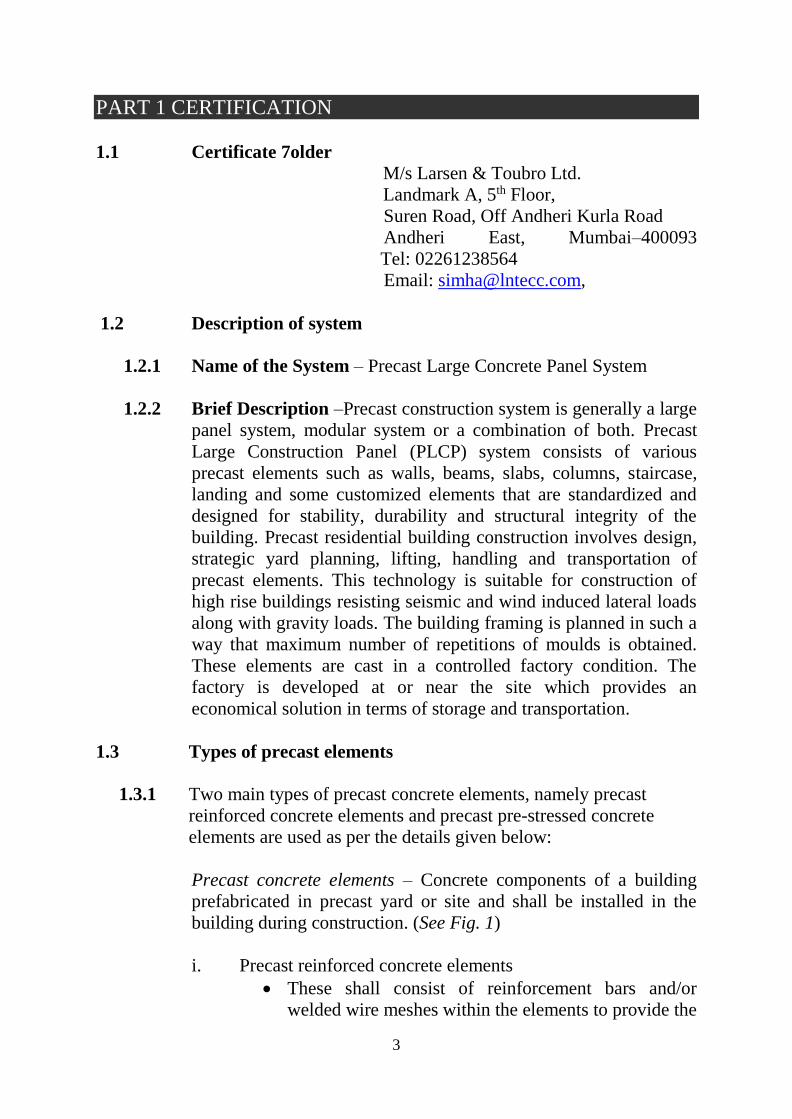
1.4.2 Waterproofing
External joints shall be sealed with baker rods and sealants after
filling the joints with grout to avoid the leakage. Additional
waterproofing treatment shall be provided at external joints and wet
areas to ensure water tightness. (See Fig. 8)
Fig. 8 Cementitious waterproofing membrane
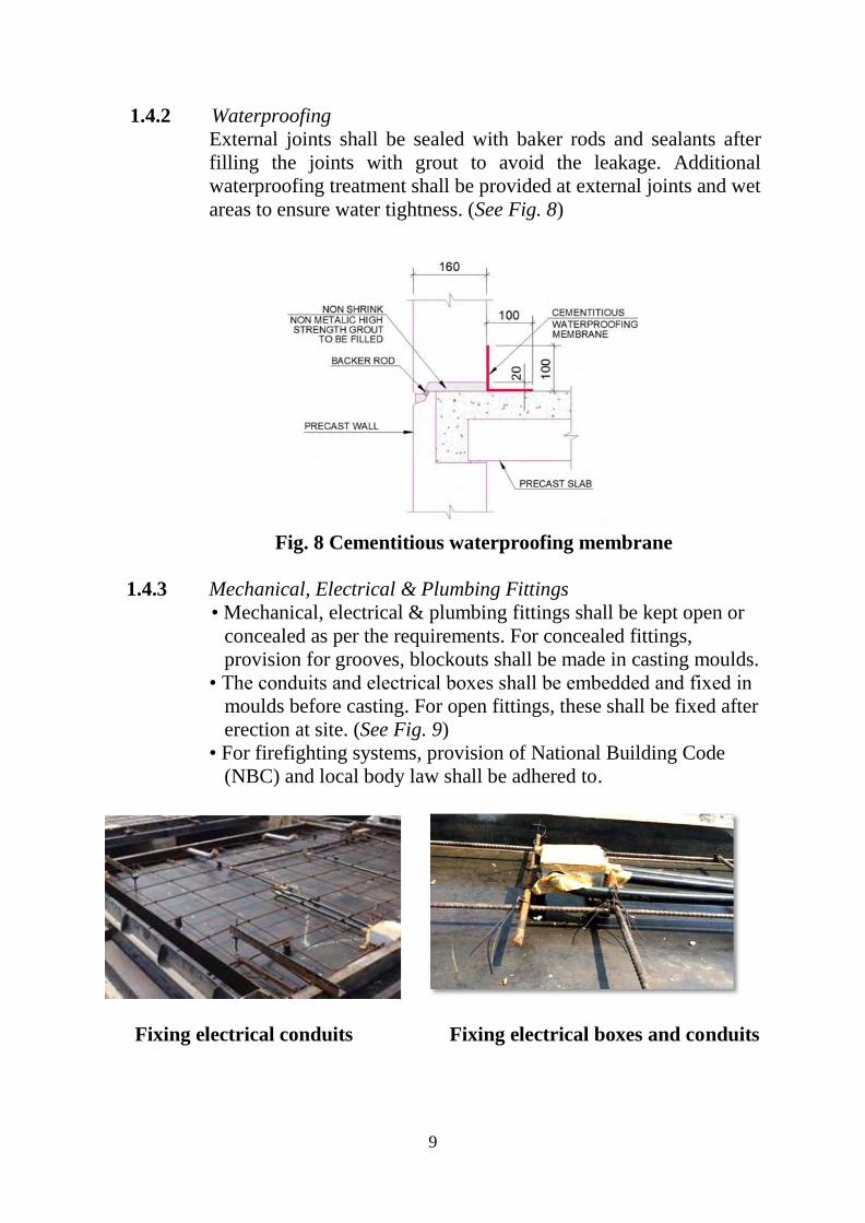
1.4.3 Mechanical, Electrical & Plumbing Fittings
• Mechanical, electrical & plumbing fittings shall be kept open or
concealed as per the requirements. For concealed fittings,
provision for grooves, blockouts shall be made in casting moulds.
• The conduits and electrical boxes shall be embedded and fixed in
moulds before casting. For open fittings, these shall be fixed after
erection at site. (See Fig. 9)
• For firefighting systems, provision of National Building Code
(NBC) and local body law shall be adhered to.
Fixing electrical conduits Fixing electrical boxes and conduits

10
Laying conduits on slab Plumbing
Fig. 9 Mechanical, Electrical & Plumbing Fittings
1.4.4 Fire Rating
• Precast concrete shall be designed for fire rating of 1 to 2 hours
based on codal requirements.
• Minimum precast concrete wall thickness of 120 mm shall be
provided for 1 hour fire rating as per IS 456:2000.
1.4.5 Finishes
• Variety of shapes, colours, textures and finishes may be obtained
with precast concrete.
• The surface treatments shall be done by rebating, grooving,
surface coatings, cement based renders, oxide coloring etc.
• Precast concrete facades of various shapes, colours and textures
may be moulded and installed.
1.5 Design Considerations and Requirements
1.5.1 Structural Design Approach
The overall behavior of a precast structure is dependent on the
behavior of the connections which must provide:
Resistance to all design forces
Ductility in case of excessive deformation
Resistance to volume changes and related forces
Adequate durability
Required fire resistance
Feasible production considerations
Feasible construction considerations

11
1.5.2 Floor panels
For reinforced concrete floors, concrete of minimum grade M 30
shall be used. Pre-stressed concrete floor units shall satisfy the
strength requirements followed in usual design practice, namely, a
minimum of M 35 for post-tensioned and pre-tensioned works. The
thickness of the floor panel shall be such that the serviceability
requirements are satisfied. The minimum thickness of concrete
layer for cored slab is 50 mm. Panels shall be designed in
accordance with the recommendations given in IS 456:2000
governing reinforcement and detailing.
1.5.3 Walls
Structural load bearing walls shall be designed as per codal
provisions of IS 456:2000 and IS 13920:1993 as applicable.
Internal non load bearing walls should be designed as plain
concrete walls with nominal reinforcement for handling and
erection stresses. Such walls may also be built using alternate
partition wall systems. For concrete walls, minimum concrete
grade should be M10.
1.5.4 Connections
The PLCP System is designed using the emulative detailing
concept such that once the structure is completed it will behave
similar to an equivalent RCC System and will provide necessary
strength and ductility. Typically, wet connections are used to
achieve the emulative behavior in the PLCP System.
1.5.5 Design Philosophy
The precast structure should be analysed as a monolithic one and
the joints in them designed to take the forces of an equivalent
discrete system. Resistance to horizontal loading shall be provided
by having appropriate moment and shear resisting joints. The
individual components shall be designed, taking into consideration
the appropriate end conditions and loads at various stages of
construction. The components of the structure shall be designed for
loads in accordance with IS 875 (Parts 1-5):1987 and IS 1893 (Part
1):2002. In addition members shall be designed for handling,
erection and impact loads that might be expected during handling
and erection.
1.5.5.1 Structural system
The structural system of superstructure consists of precast
construction of RCC wall, columns, slabs and beams. Floor slab

12
shall be considered to act as a rigid diaphragm to transfer the lateral
forces to walls/column. Ground floors are mostly constructed by
conventional method i.e. cast-in-situ construction. It shall be
designed to take the cantilever load of the above floors. First floor
to higher floors shall be constructed by precast technology i.e.
precast wall and solid floor slab system.
1.5.5.2 Fire rating
Period of fire resistance of RCC buildings is based on NBC
requirements. To meet the fire rating requirement, provision
specified in IS 456:2000 shall be followed.
1.5.5.3 Design loads
1. Dead loads – the dead load shall comprise of self-weight of all
the frames and shell elements modelled in the structure as well
as self-weight of slabs.
2. Imposed loads – The imposed loads that are envisaged to act
permanently (whichever applicable) are as follows:
i. Waterproofing: Shall depend on the thickness, slope and
kind of material to be used for waterproofing
ii. False ceiling/Internal partitions: False ceiling load shall be
calculated based on type of material and thickness using unit
weights specified in IS 875(Part 1):1987. Partition loads
shall be as per actuals.
iii. All structural elements: Layout and size of elements shall be
followed as per structural requirements.
1.5.5.4 Wind load
The wind pressure shall be calculated on the basis of data specified
in clause 5.3 of IS 875 (Part 3):1987.
1.5.5.5 Earthquake loads
For seismic purpose, the PLCP System design shall be in
compliance with the provisions of IS 1893:2002.
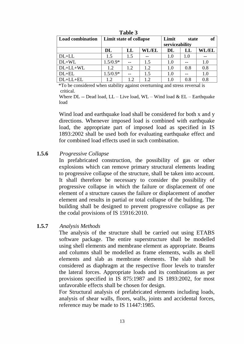
1.5.5.6 Load combinations
The various loads shall be combined as given below and as
specified in IS 875 (Part 5):1987; whichever combination produces
the most unfavorable effect in the building foundation or structural
member concerned shall be adopted:
13
Table 3 Load combination Limit state of collapse Limit state of
serviceability
DL LL WL/EL DL LL WL/EL
DL+LL 1.5 1.5 -- 1.0 1.0 --
DL+WL 1.5/0.9* -- 1.5 1.0 -- 1.0
DL+LL+WL 1.2 1.2 1.2 1.0 0.8 0.8
DL+EL 1.5/0.9* -- 1.5 1.0 -- 1.0
DL+LL+EL 1.2 1.2 1.2 1.0 0.8 0.8
*To be considered when stability against overturning and stress reversal is
critical.
Where DL -- Dead load, LL – Live load, WL – Wind load & EL – Earthquake
load
Wind load and earthquake load shall be considered for both x and y
directions. Whenever imposed load is combined with earthquake
load, the appropriate part of imposed load as specified in IS
1893:2002 shall be used both for evaluating earthquake effect and
for combined load effects used in such combination.
1.5.6 Progressive Collapse
In prefabricated construction, the possibility of gas or other
explosions which can remove primary structural elements leading
to progressive collapse of the structure, shall be taken into account.
It shall therefore be necessary to consider the possibility of
progressive collapse in which the failure or displacement of one
element of a structure causes the failure or displacement of another
element and results in partial or total collapse of the building. The
building shall be designed to prevent progressive collapse as per
the codal provisions of IS 15916:2010.
1.5.7 Analysis Methods
The analysis of the structure shall be carried out using ETABS
software package. The entire superstructure shall be modelled
using shell elements and membrane element as appropriate. Beams
and columns shall be modelled as frame elements, walls as shell
elements and slab as membrane elements. The slab shall be
considered as diaphragm at the respective floor levels to transfer
the lateral forces. Appropriate loads and its combinations as per
provisions specified in IS 875:1987 and IS 1893:2002, for most
unfavorable effects shall be chosen for design.
For Structural analysis of prefabricated elements including loads,
analysis of shear walls, floors, walls, joints and accidental forces,
reference may be made to IS 11447:1985.

14
1.5.8 Design Methodology
All structural elements shall be designed according to the Limit
state method as specified in IS 456:2000.
For design of ties, key elements and joints etc. reference may be
made to IS 15916:2010.
1.6 Production, Installation and Transportation Machinery
1.6.1 Production Machinery
1) Steel mould for wall/beam/slab panel/staircase
2) Batching plant
3) Transit mixers
4) Vibrators
5) Concrete buckets
1.6.2 Transportation Machinery
1) Lifting beam/ lifting clamps
2) Ropes & lifting hooks
3) Trailer – 20 MT capacity
4) Wooden runner of size 40 x 60 mm/ 100 x 125 mm
1.6.3 Cranes and Loaders
1) Tower crane of 5.7 MT, 6.9 & 7.2 MT load carrying capacity
and operating radius of 40 to 45 m.
2) Gantry cranes of 10 MT, 20 MT & 30 MT capacity and span of
20 to 25 m.
3) Wheel loader of 1.9 cum capacity
4) Skid steer loader
5) Truck mounted knuckle boom crane of 7 MT capacity
1.7 Basis of Assessment
1.7.1 Scope of Assessment
1.7.1.1 Scope of assessment includes conformance of manufactured pre-
cast concrete panels to the specified requirements for use in the
building construction.
1.7.2 Assessment Assessment of the suitability of the Prefabricated Large Concrete
Panel System manufactured is based on:

15
i) Inspection of production and erection facilities at site during
visit of some of TAC members and Officers of BMTPC.
ii) Indian Institute of Technology (IIT) Madras – Suitability of
Precast Concrete Large Panel System for Mass Housing
Projects.
iii) Indian Institute of Technology (IIT) Delhi – Concept
Approval for Precast Technology for building construction.
iv) Veermata Jijabai Technology Institute (VJTI), Mumbai --
Concept Approval for Precast Technology for building
construction.
v) Indian Institute of Technology (IIT) Madras – Design &
Construction Methodology Review for Rehab Bhiwada
Precast Project, Mumbai.
vi) Verification of Thermal Performance Reports – Evaluating
RCC Wall apartments in Ahmedabad & Chennai by Indian
Institute of Science, Bangalore.
vii) Quality Assurance System followed by the Certificate holder
for quality control of the system. Quality Assurance Plan is
given at Annex. I.
1.8 Use of the Prefabricated Large Concrete Panel System
1.8.1 The system shall be used for mass housing projects and
commercial buildings, etc.
1.8.2 Special Aspects of use:
i) The building to be constructed using the System shall
be in accordance with the specifications and manufacturing
& construction process prescribed by the manufacturer and
designed by competent structural Engineers.
ii) Plumbing & Electrical services, Doors & windows and
Utilities etc. shall be governed by the provisions and details
agreed between the manufacturer and developer.
iii) Buildings to be constructed with the System should
be constructed only with technical support or supervision by
qualified engineers and builders, based on structural designs
and Seismic evaluation & Wind forces carried out to comply
with prevailing standards; this is applicable even for low-rise
and affordable mass housing to provide safety of structures.
iv) It is strongly recommended that structural engineers
and building designers associated with precast construction
should be thoroughly familiar with the various structural
aspects. It is also recommended that Architects and

16
Construction Engineers who undertake such building design
and construction gain familiarity with the properties and
materials, characteristics of the System and its applications.
1.8.3 Experience in actual use Provident Sunworth Project comprising of B+S+12 storey
buildings having 62 towers and 5952 units at Kengeri, Bangaluru
being constructed by the firm was inspected by a team comprising
BMTPC Officers and some of TAC members in December, 2015.
The quality of work was found to be satisfactory.
1. 9 Conditions of Certification
1.9.1 Technical Conditions
1.9.1.1 Raw materials and the finished precast elements shall conform to
the requirements of the prescribed specifications.
1.9.1.2 The production capability and quality of the precast elements vis-à-
vis requirements specified and competence of the technical persons
for design and proper erection of the panels at site shall need
verification for each plant/ establishment engaged in the production
and execution of the system.
The design assumptions, detailed calculations, references to
necessary and detailed design drawings shall be made available on
demand, if required. The structural design calculations should
clearly demonstrate structural integrity and stability including
connection details.
1.9.2 Quality Assurance
1.9.2.1 The Certificate Holder shall implement & maintain a quality
assurance system in accordance with Scheme of Quality Assurance
(SQA) given in the Annex I attached with this Certificate.
1.9.2.2 Structures using the panels shall be designed as per Clause 1.4
and executed as per provisions of this PAC.
1.9.3 Scope of Inspection
Scope of inspection included the verification of production,
performance and erection at site including competence of technical
personnel and status of quality assurance in the factory.

17
1.9.4 Manufacturing and Erection Facilities
Manufacturing and erection facilities available were found to be
suitable to produce and erect the precast concrete panels as per the
specifications.
1.9.5 Handling of User Complaints
1.9.5.1 The Certificate holder shall provide quick redressal to consumer/
user complaints proved reasonable & genuine and within the
conditions of warranty provided by it to customer/purchaser.
1.9.5.2 The Certificate holder shall implement the procedure included in
the SQA. As part of PACS Certification he shall maintain data on
such complaints with a view to assess the complaint satisfaction
and suitable preventive measures taken.
1.10 Certification
On the basis of assessment given in Part 3 of this Certificate &
subject to the conditions of certification, use & limitations set out
in this Certificate and if selected, installed & maintained as set out
in Part 1 & 2 of this Certificate, the system covered by this
Certificate is fit for use set out in the Scope of Assessment.
PART 2 CERTIFICATE HOLDER’S TECHNICAL SPECIFICATIONS
2.1 General
The PAC holder shall manufacture the precast elements in
accordance with the requirements specified in the Prefabricated
Large Concrete Panel System.
2.2 Specifications for the System
2.2.1 Raw Materials
1. Ordinary Portland Cement: Shall be of 43 grade as per IS
8112:1989.
2. (i) Fine aggregate (M Sand): Shall be as per IS 383:1970 & IS
1542:1992 and 4.7 mm.
3. Coarse Aggregates: Shall be as per IS 383:1970 and of 20
mm, 40 mm size
4. Steel reinforcement: Shall be as per IS 1786:2008
5. Concrete: The grade of concrete shall be M 30 and slump for
walls, floors and roofs shall be as per IS 456:2000.

18
6. Brick masonry: Shall be as per IS 1905:1987
7. Solid Block work: Shall be as per IS 2185 (Part 1):1979
8. Aluminium: Shall be as per IS 733:1983
9. Glass: Shall be as per IS 2835:1987
10. Non shrunk non-metallic grout: Cement based flowable grout
shall have compressive strength of 65 N/mm2, flexural strength
of 9 N/mm2 at 28 days and E-modulus of 37000 N/mm2. (ASTM C
109 & ASTM C 293-79) 11. Water proofing membrane: Fibre reinforced repair mortar shall
have compressive strength of 45 N/mm2 at 28 days and density
2250 kg/m3 (ASTM C 109).
12. Baker Rod: Closed cell polymer based product shall have
compressive strength of 0.45 kg/cm2 min. at 25% deflection,
density 22 kg/m3 min. and water absorption 0.14 gm/cm3 max.
13. Corrugated sleeve: Hot dipped galvanized prime steel sheet shall
be as per IS 277:2003.
2.2.2 Inspections & Testing
● Shall be done at appropriate stages of manufacturing process
and execution process.
● The inspected panels shall be stored carefully to ensure that no
damage occurs during transportation.
● As part of quality assurance, regular in- process inspections
shall be carried out by the trained personnel of the PAC holder.
2.3 Tolerances of Precast Elements
2.3.1 Casting Tolerances of Precast Elements
2.3.1.1 Casting tolerances of precast elements are given in Table 4:
Table 4 S. No. Elements Recommended tolerance
1. Length
1.1 Slab, plain wall panel
& beam
± 5 mm or 0.1% whichever is greater
1.2 Large panel fabrication ± 0.1% subject to max. of + 5 mm to – 10
mm
1.3 Columns ± 10 mm
2. Thickness/ cross-sectional dimensions
2.1 Slab, plain wall panel
& beam
± 3 mm or 0.1% whichever is greater
2.2 Large panel fabrication,
floor/roof slabs
± 2 mm upto 300 mm wide
± 3 mm for > 300 mm wide
2.3 Columns ± 4 mm
3 Straightness/bow
3.1 Ribbed/hollow slab, ± 5 mm or 1/750th of length whichever is
19
large panel fabrication
and ribbed/plain wall
panel
greater
4 Squareness – While considering the squareness of the corner, the
longer of two adjacent sides being checked shall be taken as the base
line
4.1 Concrete floor/roof
slabs & plain wall
panel
The shorter side shall not vary in length
from the perpendicular by more than 5 mm
4.2 Large panel fabrication The shorter side shall not be out of square
line for more than + 2 mm to -5 mm
5 Flatness – The max. deviation from 1.5 m straight edge placed in any
position on a nominal plain surface shall not exceed:
5.1 Large panel fabrication ± 3 mm 5.2 Cellular concrete
floor/roof slabs ± 4 mm or max. of 0.1% length
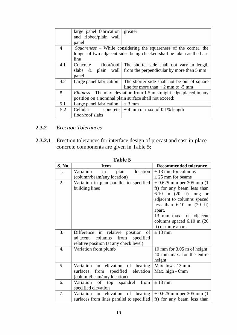
2.3.2 Erection Tolerances
2.3.2.1 Erection tolerances for interface design of precast and cast-in-place
concrete components are given in Table 5:
Table 5 S. No. Item Recommended tolerance
1. Variation in plan location
(column/beam/any location)
± 13 mm for columns
± 25 mm for beams
2. Variation in plan parallel to specified
building lines
+ 0.625 mm per 305 mm (1
ft) for any beam less than
6.10 m (20 ft) long or
adjacent to columns spaced
less than 6.10 m (20 ft)
apart.
13 mm max. for adjacent
columns spaced 6.10 m (20
ft) or more apart.
3. Difference in relative position of
adjacent columns from specified
relative position (at any check level)
± 13 mm
4. Variation from plumb 10 mm for 3.05 m of height
40 mm max. for the entire
height
5. Variation in elevation of bearing
surfaces from specified elevation
(column/beam/any location)
Max. low - 13 mm
Max. high - 6mm
6. Variation of top spandrel from
specified elevation ± 13 mm
7. Variation in elevation of bearing
surfaces from lines parallel to specified + 0.625 mm per 305 mm (1
ft) for any beam less than

20
grade lines 6.10 m (20 ft) long or
adjacent to columns spaced
less than 6.10 m (20 ft)
apart.
13 mm max. for any beam
6.10 m (20 ft) in length or
for adjacent columns
spaced 6.10 m (20 ft) or
more apart. 8. Variation from specified bearing length
on support 19 mm
9. Variation from specified bearing width
on support 13 mm
10. Jog in alignment of matching edges 13 mm
2.3.2.2 Beam erection tolerances
The primary control surfaces for beam erection tolerances are
usually as given in Table 6, although this needs to be determined
on a job-by-job basis: (See Fig. 10)
Table 6 S. No. Item Recommended
tolerance
1. Plan location for building grid datum ± 25 mm
2. Bearing elevation from nominal elevation from support: 2.1 Maximum low 13 mm
2.2 Maximum high 6 mm
3. Maximum plumb variation over height of component
3.1 Per 305 mm (1 ft) height 3 mm
3.2 Max. at rectangular or L beam 3 mm
3.3 Max. at inverted T beam 19 mm
4. Maximum jog in alignment of matching
edges—visually non-critical edges
13 mm
5 Joint width
5.1 Hidden joints ± 19 mm
5.2 Exposed structural joints not visually critical ± 13 mm
6. Bearing length (span direction) ± 19 mm
7. Bearing width ± 13 mm
Note: When bearing pads are used at unarmed edges, there should be a set
back of min. 12.5 mm from the face of support or at least the chamfered
dimensions at chamfered edges.

21
Fig. 10 Beam Erection Tolerances
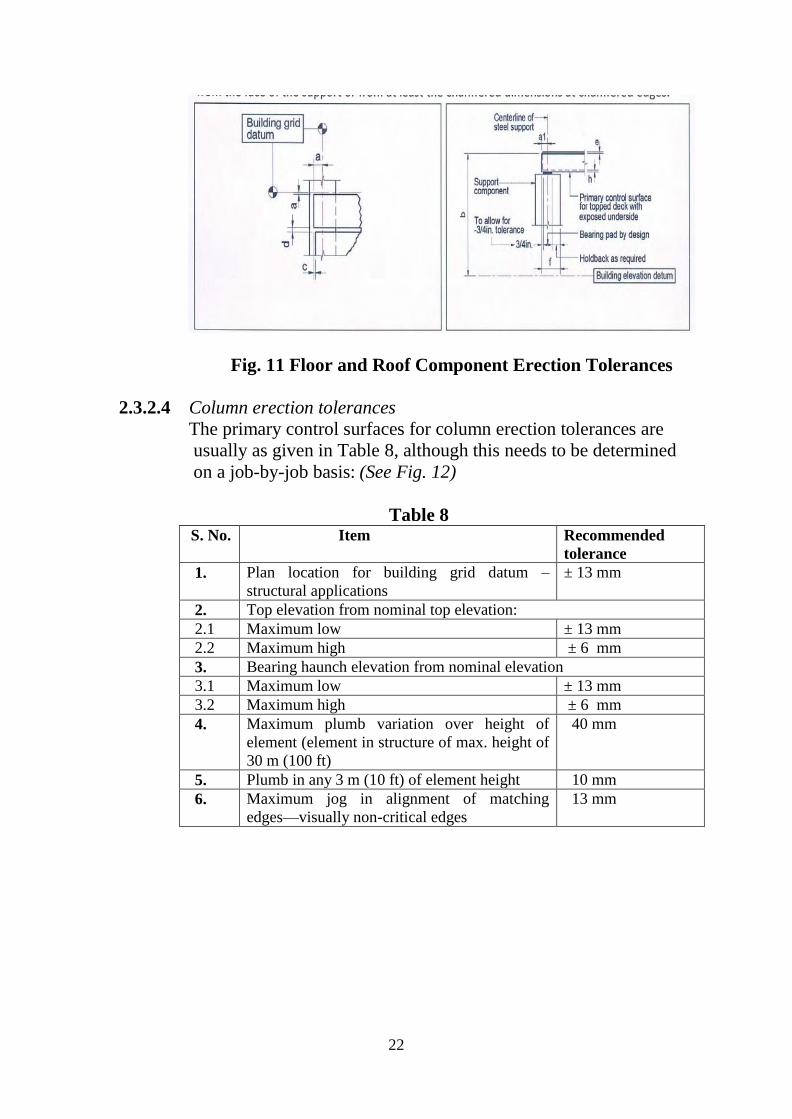
2.3.2.3 Floor and roof component erection tolerances
The primary control surfaces for floor and roof component erection
tolerances are usually as given in Table 7. Typically, there is no
vertical, control surface and in some scenarios, there are no
primary control surfaces at all. This needs to be determined on a
job-by-job basis. (See Fig. 11)
Table 7 S. No. Item Recommended
tolerance
1. Plan location for building grid datum ± 25 mm
2. Top elevation from building elevation datum at
component ends—covered with topping ± 19 mm
3. Maximum jog in alignment of matching edges
(both topped and un-topped construction)
25 mm
4. Joint width
4.1 Off to 12.12 m component ± 13 mm
4.2 12.12 m to 18.28 m component ± 19 mm
5. Differential top elevation as erected (for units
of same design and length) – field topped
19 mm
6. Bearing length (span direction) ± 19 mm
7. Differential bottom elevation of exposed
hollow-core slabs
6 mm
22
Fig. 11 Floor and Roof Component Erection Tolerances
2.3.2.4 Column erection tolerances
The primary control surfaces for column erection tolerances are
usually as given in Table 8, although this needs to be determined
on a job-by-job basis: (See Fig. 12)
Table 8 S. No. Item Recommended
tolerance
1. Plan location for building grid datum –
structural applications
± 13 mm
2. Top elevation from nominal top elevation: 2.1 Maximum low ± 13 mm
2.2 Maximum high ± 6 mm
3. Bearing haunch elevation from nominal elevation
3.1 Maximum low ± 13 mm
3.2 Maximum high ± 6 mm
4. Maximum plumb variation over height of
element (element in structure of max. height of
30 m (100 ft)
40 mm
5. Plumb in any 3 m (10 ft) of element height 10 mm
6. Maximum jog in alignment of matching
edges—visually non-critical edges
13 mm

23
Fig. 12 Column Erection Tolerances
2.3.2.5 Structural wall panel erection tolerances
The primary control surfaces for column erection tolerances are
usually as given in Table 9, although this needs to be determined
on a job-by-job basis: (See Fig. 13)
Table 9 S. No. Item Recommended
tolerance
1. Plan location for building grid datum ± 13 mm
2. Top elevation from nominal top elevation: 2.1 Exposed individual panel ± 13 mm
2.2 Non exposed individual panel ± 19 mm
2.3 Exposed relative to adjacent panel ± 19 mm
2.4 Non exposed relative to adjacent panel ± 19 mm
3. Support elevation from nominal elevation
3.1 Maximum low 13 mm
3.2 Maximum high 6 mm
4. Maximum plumb variation over height of 40 mm

24
structure or over 30 m (100 ft), whichever is
less
5. Plumb in any 3 m (10 ft) of element height 10 mm
6. Maximum jog in alignment of matching edges 13 mm
7. Joint width (governs over joint taper) ± 9 mm
8. Joint taper over length of panel 13 mm
9. Joint taper over 3 m (10 ft) length 9 mm
10. Maximum jog in alignment of matching edges
10.1 Exposed to view 9 mm
10.2 Non Exposed to view 19 mm
11. Differential bowing or camber as erected
between adjacent members of the same design
13 mm
Fig. 13 Structural Wall Panel Erection Tolerances

25
2.3.2.6 Stair unit erection tolerances
The primary control surface for stair units is the top of loading at
floor levels. The tolerances listed in Table 10 are the same whether
landings are monolithic or separate pieces. Local building codes
may require more restrictive riser-height tolerance, which could
also effect the product tolerance. (See Fig. 14)
Table 10 S. No. Item Recommended
tolerance
1. Plan location for building grid datum ± 13 mm
2. Differential elevation as erected ± 9 mm 3. Joint width ± 19 mm
4. Maximum jog in alignment of matching edges 25 mm
5 Maximum jog in alignment of stair tread
nosing (this tolerance over rides 4, if required)
13 mm
6. Maximum jog in alignment of matching edges
at primary control surfaces*
9 mm
7. Bearing (in span direction) ± 19 mm
* At stair units that have pre-topped precast buildings, the maximum jog
between stair units as well as from stair unit to finish floor shall not exceed 6
mm. However, units which have landings that are topped have more leeway.
Elevation

26
Plan
Fig. 14 Stair Unit Erection Tolerances
2.4 Implementation of Precast Elements
2.4.1 Casting Concrete
The procedure for casting concrete shall be as follows:
i. Precast concrete elements shall be produced on
horizontal/vertical, flat steel surfaced tilting tables.
ii. Prior to casting, electrical conduits and other required shall
be fixed in position and the mould treated with mould release
agent
iii. Steel reinforcement shall be kept in position using adequate
spacers to ensure correct position and concrete cover.
iv. After that side shutter sides shall be fixed. The high quality
concrete shall be transported from batching plant to the
precast yard through transit mixer.
v. Thereafter, concrete shall be carried to mould by gantry
crane with concrete bucket.
vi. During casting, table vibrators (as & when required) shall be
used to achieve the best compaction. Top surface shall be
finished with hand operated trowel which gives smooth
finish.
vii. Care should be taken on embedded items while concreting.
viii. After casting, all exposed surfaces shall be covered with a
tarpaulin (as and when required) to avoid vaporization.
Casted elements shall be de-moulded once the strength meets
the design requirements and the units are then shifted to the
stockyard. Thereafter, curing shall be carried out for 5 days.

27
The details of the precast yard where casting of concrete is done
are given in Annex. IV.
2.4.2 Curing
The curing of the prefabricated elements may be done by the
normal methods of curing by sprinkling water and keeping the
elements moist. This can also be done in the case of smaller
elements by immersing them in specially made water tanks.
2.4.3 Screed Concrete for Flooring
The procedure for screed concrete shall be as follows:
i. The surface for screed concrete shall be clean, free from
dust, loose materials, lumps and foreign material.
The screed shall generally be provided over the entire slab. In this
case the entire slab shall act as a continuous structural diaphragm
providing optimum load transfer mechanism for lateral loads. The
screed shall be treated as a part of the compression zone for gravity
loads on the slab. The design shall consider composite action
between the slab & screed and compressive strength of screed in
slab. Further, the interface shear between the slab & screed shall be
checked for verifying adequate shear transfer capacity at the
interface.
Screed on haunches may be provided, only if the conduits are
exposed, with the mutual agreement between the project authority
and the PAC holder. In such cases, additional water proofing
treatment of a reputed company shall be provided at the precast slab
and site concrete stitch.
ii. Electrical conduits or any other embedment shall be laid as
per approved drawing before screed concrete flooring
iii. The reference level from main survey pillars shall be
transferred and marked on side channels
iv. While marking level, sloping direction in flooring shall be
taken care as per approved drawing
v. Before laying the concrete, cement slurry shall be spread on
the slab surface for better bonding and filling of gaps
between wall and slab soffit junction.
vi. The concrete should be placed from one end and shall be
compacted immediately after placing and levelled uniformly.
vii. The vibrator should be applied smoothly and concrete
compacted well.
viii. The concrete shall be allowed to set so as to be in dry
condition.

28
ix. The trowelling shall start after concrete is set and reach dry
condition.
x. Curing shall be done by using bunds over the screed surface
/wet hessian cloth.
2.4.4 De-moulding and Stacking
The procedure for de-moulding and stacking shall be as follows:
2.4.4.1 Lifting of elements from mould
i. It must be ensured that all the elements should have
identification mark.
ii. It must be ensured that all side shutters are loosened so that
the elements may be lifted without any damages.
iii. Before demoulding, it must be ensured that compressive
strength of the cubes should meet the specified requirements.
iv. The lifting clamps/clutches shall be fixed to lifting beam at
proper positions.
v. Then the elements shall be lifted carefully to the stocking
area.
2.4.4.2 Stacking of elements
i. The surface of stacking area should be horizontal.
ii. The wooden runner shall be placed perpendicular to lifting
points and the elements placed over runner.
iii. Number of the elements per lot should not exceed man
height.
iv. In case of vertical stacking, the gap between the elements
should be 150 mm to 200 mm.
v. Stacking shall be done in such a way that slabs of longer
span should be placed below that of shorter span.
2.4.5 Transportation of Elements
The process of transportation of precast elements from yard to site
shall be as follows:
2.4.5.1 Loading of slab over trailer
1. It must be ensured that the identification mark on the slab
should be the same as per dispatch list.
2. Any damage occurred during loading should be informed to the
concerned authority.
3. The lifting clamps/clutches shall be fixed to the lifting beam at
proper position.

29
4. The lifting beam shall be placed over the precast elements and
ensured that the clutches are locked properly before lifting.
5. Instruction regarding loading height, positioning of precast
elements over the trailer should be followed as per capacity of
trailer.
6. The wooden rubber shall be placed in between the slabs at 500
mm from each end.
7. Some of precast elements should be placed vertically and
transported through “A” frame fixed vehicle.
8. The slab shall not be overhanging from trailer.
9. The slab shall be tied firmly to the trailer by means of belt/rope
as moving the load without proper tie will cause damage.
10. While transporting elements vertically, the vehicle should be
loaded equally on both sides.
2.4.5.2 Unloading of slab from trailer and placing in site yard
1. Every slab shall be inspected for dimensions/identification mark
and damages etc. prior to unloading at site.
2. The stacking area should be levelled and hard enough for
stacking the elements.
3. There should be proper access for trailer movement.
2.4.6 Erection
The process of erection and installation of panels during the
construction cycle by using tower cranes shall be as follows:
1. Before starting erection a survey of the area to receive precast
elements shall be done to monitor any difference in dimensions
or levels exceeding the tolerances. In case of unacceptable
tolerances, necessary action shall be taken for rectification.
2. Installation shall be done by tower crane with sufficient
capacity. Panels shall be shifted from the stack rack/truck from
yard to the nearest point of construction site and shall be kept
above the truck during the construction or inside the storage
racks as per the site situation.
3. The necessary access for the truck to reach the nearest point of
the tower shall be prepared before starting erection of the
panels.
4. Once the truck reaches the tower, chain and lifting clutch with
required capacity and guide rope shall be attached to the precast
panels to allow the workers to control the load to its final place.
5. As the elements are lifted to its final position above the cast-in-
situ slab/precast panel, vertical and horizontal alignment of the
panel shall be adjusted. The gap between the element and
30
adjusted elements shall be maintained as per the drawings
within the allowable tolerances. Shims and spacers shall be used
for levelling and adjustment.
6. Temporary propping jacks shall be provided for restraining the
walls laterally until grouting.
7. After completion of fixing, alignment of the panels shall be
checked again.
8. Minor damages, if any to the precast panels shall be repaired by
approved materials.
9. After completion of installation and alignment, elements shall
be handed over for inspection.
10. The joints between the precast wall panels shall be filled with
joint filler material.
11. Precast slab shall be erected above the wall panels without any
scaffolding system. The electrical conduit/fitting shall be done.
After electrical works are completed, screed concrete shall be
laid over the precast slab.
12. Installation of the next floor shall start only after completion of
screed concrete of the previous floor.
13. The sequence of erection shall be as follows:
Installation of precast wall panels above cast-in-situ slab
Provide temporary props/jacks for restraining of the walls
laterally.
Grout the connection between the wall panels & ground
floor slab and the joint between each wall panel.
Installation of precast slab panels above the erected precast
wall panels.
Screed concrete above the slab after placing of electrical
conduits/fittings
Installation of the wall panels over the floor slab.
Installation of the roof panels such as parapets etc.
The production flow chart is given in Annex. II.
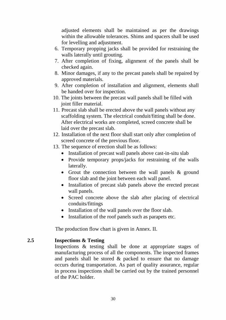
2.5 Inspections & Testing
Inspections & testing shall be done at appropriate stages of
manufacturing process of all the components. The inspected frames
and panels shall be stored & packed to ensure that no damage
occurs during transportation. As part of quality assurance, regular
in process inspections shall be carried out by the trained personnel
of the PAC holder.

31
2.6 Good Practices for Installation & Maintenance Good practice as per requirement including Do’s & Don’ts of
working with Prefabricated Large Concrete Panel System of the
manufacturer shall be followed for erection and maintenance of
these sections.
2.7 Maintenance Requirements
It is assumed that no special maintenance is required during
intended working life. Should repairs prove necessary, it shall ably
be carried out by the trained persons using appropriate products
and materials.
2.8 Skilled /Training Needed for Installation
Special training shall be required to get necessary skill set for
assembly of prefabricated large concrete panels and their erection.
Moreover, workers shall be trained/ oriented on handling and
installation of modules, panels etc. and support system with all
required safety measures taken including heavy hats, protective
shoes etc. PAC holder shall arrange training of workers, as required
in this regard.
2.9 Guarantees/Warranties Provided by the PAC Holder
PAC holder shall provide necessary guarantees/ warranties of the
system to the client.
2.10 Responsibility
● Specific design using Prefabricated Large Concrete Panel System
is the responsibility of the designer with the instructions,
supervision and approval of L & T Ltd.
● Quality of maintenance of the building is the responsibility of the
building owner.
● Providing necessary facilities and space for movement of
machines and vehicles is the responsibility of the building
developer.
PART 3 BASIS OF ASSESSMENT AND BRIEF DESCRIPTION OF
ASSESSMENT PROCEDURE
3.1 Basis of Assessment
The technical assessment was done as per provisions of the
Standards listed in Part 5 of this Certificate.

32
3.2 Site Inspections
Inspection of production, casting yard and erection process was
done by some of the TAC members and Officers of BMTPC on the
construction of Provident Sunworth Project comprising of B+S+12
storey buildings having 62 towers and 5952 units at Venkatapura
Kengeri Hobli, Bangaluru. Firm has got necessary manufacturing,
transportation and erection machineries and equipment at site as
per the process description given for manufacturing and erection of
the precast panels.
3.3 Approvals Obtained
3.3.1 Concept Approval for Precast Technology for Building Construction
from IIT Delhi and Veermata Jijabhai Technological Institute,
Mumbai in November, 2011.
The views given by the institutes are as follows:
1. It can be used for structures under anticipated type of
lateral loads, if structural design is correctly carried out as
per the relevant codes of practice in India.
2. It can be used in any seismic zone of India (i.e. seismic
zone II to V as per IS 1893:2002); however, detailed
design needs to be carried out for a specific project.
3. Buildings constructed by using this technology can resist
design wind load; however, detailed design needs to be
carried out for a specific project.
4. If it is constructed with proper care, the useful life
(durability) can be assumed to be equal to its design life
i.e. 50 years.
5. This technology can be used for high rise building
construction in seismic zone II to V as per IS 1893:2002);
however, detailed design needs to be carried out for a
specific project.
3.3.2 Concept Approval for Precast Technology for Building Construction
from IIT Madras in June, 2012.
The views given by the institutes are as follows:
1. Precast design concepts adopted are consistent with
relevant provisions of international codes of practice
such as ACI, PCI and FIB.

33
2. Connection details, load path as well as force transfer at
the joints and detailed design calculations for the project,
are found to be in order.
3. Similar design/detailing can be used for high rise building
construction in other seismic zones. However, detailed
design needs to be carried out for a specific project.
3.3.3 Suitability of Precast Concrete Large Panel system for Mass
Housing Projects by IIT Madras in March, 2015
IIT madras has recommended the adoption of this technology in
Mumbai.
3.4 Execution of Projects
The manufacturer has executed the following projects:
S.
No.
Name of Project Name of Client No. of Dwelling
units
Year of
construction
1. Pragati Towers,
Parel, Mumbai
Omkar Realtors &
Developers and L&T
Reality Joint Venture
G+23 levels,
2024 units
February 2014
2. Provident Sunworth
Project, Bangaluru
Provident, Bangaluru G+12/G+14
levels, 1200 units
March 2016

34
This certificate holder shall satisfy the following conditions:
4.1 The certificate holder shall continue to have the product reviewed by BMBA.
4.2 The product shall be continued to be manufactured according to and in
compliance with the manufacturing specifications and quality assurance
measures which applied at the time of issue or revalidation of this certificate. The
Scheme of Quality Assurance separately approved shall be followed.
4.3 The quality of the product shall be maintained by the certificate holder. Complete
testing facilities shall be installed for in-process control.
4.4 The product user should install, use and maintain the product in accordance with
the provisions in this Certificate.
4.5 This certificate does not cover uses of the product outside the scope of this
appraisal.
4.6 The product is appraised against performance provisions contained in the
standards listed in Part-V. Provisions of any subsequent revisions or provisions
introduced after the date of the certificate do not apply.
4.7 Where reference is made in this Certificate to any Act of Parliament of India,
Rules and Regulations made there under, statutes, specifications, codes of
practice, standards etc. of the Bureau of Indian Standards or any other national
standards body and the International Organization for Standardization (ISO),
manufacturer’s company standards, instruction/manual etc., it shall be construed
as reference to such publications in the form in which they were in force on the
date of grant of this Certificate (and indicated in Part V to this Certificate)
4.8 The certificate holder agrees to inform BMBA of their clients with details of
construction on six monthly basis.
4.9 The certificate holder agrees to provide to BMBA feedback on the complaints
received, the redressal provided, and the time taken to provide redressal on
complaint to complaint basis as soon as redressal is provided. BMBA agrees to
provide the certificate holder the user feedback received by it, if any.
4.10 If at any time during the validity period, PACH is unable to fulfill the
conditions in his PAC, he should on his own initiative suspend using the PAC
and notify Chairman, PAC the date from which he has suspended its use, the
reason for suspension and the period by which he will be able to resume. He
shall not resume without the prior permission of BMBA. He shall also inform,
simultaneously, his agents, licensees, distributors, institutional, government,
public sector buyers, other buyers and all those whom he has informed about
his holding the PAC. He shall also inform all those who buy his product(s)
during the period of suspension. He shall provide to BMBA at the earliest the
list of who have been so informed by him.
PART 4 STANDARD CONDITIONS


36
PART 5 LIST OF STANDARDS & CODES USED IN ASSESSMENT
5.1 Standards - These Standards are referred for carrying out particular tests
only and do not specify the requirement for the whole product as such.
5.1.1 IS 456:2000 – Code of Practice for Plain and Reinforced Concrete
5.1.2 IS 875 (Part 1):1987 – Code of Practice for Design loads (other than
earthquake) of buildings and structures – unit weight of building and stored
materials
5.1.3 IS 875 (Part 2):1987 – Imposed loads
5.1.4 IS 875 (Part 3):1987 – Wind loads
5.1.5 IS 875 (Part 4):1987 – Snow loads
5.1.6 IS 875 (Part 5):1987 – Special loads and load combinations
5.1.7 IS 1786: 2008 – High strength deformed bars and wires for concrete
reinforcement
5.1.8 IS 1893 (Part 1):2002 – Criteria for Earthquake Resistant Design of
Structures
5.1.9 IS 1904:2005 – Code of practice for design and construction of
foundations in soils – general requirements
5.1.10 IS 2062:1992 – Hot Rolled Medium and High Tensile Structural
Steel
5.1.11 IS 7215:1974 – Tolerances for Fabrication of Steel Structures
5.1.12 IS 9103:1999 – Specifications for Concrete admixtures
5.1.13 IS 11447:1985 – Code of practice for construction of large panel
prefabricates
5.1.14 IS 13920: 1993 – Code of practice for ductile detailing of RCC structures
subjected to seismic forces.
5.1.15 IS 15916:2010 -- Code of practice for design and erection using
prefabricated concrete


38
PART 6 ABBREVIATIONS
Abbreviations
BMBA Board of Agreement of BMTPC
BMTPC Building Materials and Technology Promotion
Council
CPWD Central Public Works Department
ED Executive Director of BMTPC
IO Inspecting Officer
MS Member Secretary of BBA
PAC Performance Appraisal Certificate
PACH PAC Holder
PACS Performance Appraisal Certification Scheme
SQA Scheme of Quality Assurance
TAC Technical Assessment Committee (of BMBA)

39
PERFORMANCE APPRAISAL CERTIFICATION SCHEME - A BRIEF
Building Materials & Technology Promotion Council (BMTPC) was set up by the
Government of India as a body under the Ministry of Housing &Urban Poverty
Alleviation to serve as an apex body to provide inter-disciplinary platform to promote
development and use of innovative building materials and technologies laying special
emphasis on sustainable growth, environmental friendliness and protection, use of
industrial, agricultural, mining and mineral wastes, cost saving, energy saving etc.
without diminishing needs of safety, durability and comfort to the occupants of
buildings using newly developed materials and technologies.
During the years government, public and private sector organizations independently or
under the aegis of BMTPC have developed several new materials and technologies.
With liberalization of the economy several such materials and technologies are being
imported.
However, benefits of such developments have not been realized in full measure as
understandably the ultimate users are reluctant to put them to full use for want of
information and data to enable them to make informed choice.
In order to help the user in this regard and derive the envisaged social and economic
benefits the Ministry of Housing &Urban Poverty Alleviation has instituted a scheme
called Performance Appraisal Certification Scheme (PACS) under which a
Performance Appraisal Certificate (PAC) is issued covering new materials and
technologies. PAC provides after due investigation, tests and assessments, amongst
other things information to the user to make informed choice.
To make the PACS transparent and authentic it is administered through a Technical
Assessment Committee
(TAC) and the BMTPC Board of Agreement (BMBA) in which scientific,
technological, academic, professional organizations and industry interests are
represented.
The Government of India has vested the authority for the operation of the Scheme
with BMTPC through Gazette Notification No. 1-16011/5/99 H-II in the Gazette of
India No. 49 dated 4th December, 1999.
Builders and construction agencies in the Government, public and private sectors can
help serve the economic, development and environmental causes for which the people
and Government stand committed by giving preference to materials and technologies
which have earned Performance Appraisal Certificates.
Further information on PACS can be obtained from the website: www.bmtpc.org

40
ANNEX I
(Clause 1.9.2.1)
QUALITY ASSURANCE PLAN FOR PREFABRICATED LARGE CONCRETRE PANEL
SYSTEM
S.No Description Test required Result required Frequency of
Testing
I. Cement
1. Setting time
i) Initial
ii) Final
50 --100 tonne – 2
100-200 tonne – 3
201-300 tonne – 4
301-500 tonne –5
501-800 tonne --6
801-1300 tonne -7
Not less than 30 minutes
Not greater than 600
minutes
50 --100 tonne – 2
100-200 tonne – 3
201-300 tonne – 4
301-500 tonne –5
501-800 tonne --6
801-1300 tonne -7
2. Fineness test 1 test per 5 samples 80% content should pass
from 0 micron sieve
1 test per 5 samples
3. Consistency As per requirement As per requirement
4. Fineness test by
specific surface
1 test per 5 samples OPC=235cm/gm
PPC+300cm/gm
1 test per 5 samples
5. Chemical test 1 test per 5 samples Magnesium Oxide < 6%
Sulphur trioxide <
2.75%
1 test per 5 samples
II. Aggregate: Coarse and Fine
A
Fine Aggregate
1.
Silt content 1 test per 150 cum
(10 kg sample)
Shall not be more than
3%
1 test per 150 cum
(10 kg sample)
B. Coarse Aggregate
1. Gradation test I test per 50 cum As per IS 2386:1963 2 tests per season
2. Impact test
I test per 50 cum As per IS 2386:1963 2 tests per season
3. Abrasion test I test per 50 cum As per IS 2386:1963
2 tests per season
4. Soundness test I test per 50 cum As per IS 2386:1963 2 tests per season
III. Concrete
1. Concrete cube
strength
Upto 5 cum –1 set
6-15 cum -2 set
16-30 cum - 3 set
31-50 cum - 4 set
51 & above -5 set
(for each 50cum or
part thereof)
As per IS 456:2000 Upto 5 cum –1 set
6-15 cum -2 set
16-30 cum - 3 set
31-50 cum - 4 set
51 & above -5 set
(for each 50cum or
part thereof)
2. Workability Once per each shift As per IS 456:2000 Once per each shift
3. Slump test Once per each shift As per IS 456:2000 Once per each shift
4. Hardened concrete Cubes 7 & 28 days
as directed
As per IS 456:2000 Cubes 7 & 28 days
as directed

41
ANNEX II
(Clause 2.4.6)
PRODUCTION FLOW CHART

42
ANNEX III (Clause 1.3.3)
TYPICAL MOULDS
1. Walls
2. POD

43
3. Slab
4. Beam

44
5. Spandrel
6. Column, Staircase and landing

45
ANNEX IV (Clause 2.4.1)
TYPICAL PRECAST YARD
1. Slab Mould
2. POD Mould

46
3. Spandrel Mould
4. Beam Mould

47
5. Battery Mould & Tilting Tables