nasa tm x-2514 memorandum c
TRANSCRIPT
NASA TECHNICAL
MEMORANDUM
NASA TM X-2514 --- c <. I
,LOAN COPY: F?EBURN AFWL @XXI&)
KlRTLANi-2 AFB, N. %
DETERMINATION OF ANGLES OF ATTACK AND SIDESLIP FROM RADAR DATA AND A ROLL-STABILIZED PLATFORM
by John S. Preisser
Ldngley Research Center
Elmnpton, Vu. 23365
NATIONAL AERONAUTICS AND SPACE ADMINISTRATION . WASHINGTON, D. C. . MARCH 1972 / .F ; I
I
https://ntrs.nasa.gov/search.jsp?R=19720012071 2018-06-14T05:35:45+00:00Z
1. Report No.
NASA TM X-2514 4. Title and Subtitle
2. Government Accession No.
DOTERMINATION OF ANGLES OF ATTACK AND SIDESLIP FROM RADAR DATA AND A ROLL-STABILIZED PLATFORM
7. Author(s)
John S. Preisser
9. Performing Organization Name and Address
NASA Langley Research Center Hampton, Va. 23365
12. Sponsoring Agency Name and Address
National Aeronautics and Space Administration Washington, D.C. 20546
15.. Supplementary Notes
T T I T I
i
TECH LIBRARY KAFB, NM
Ill llllnllllllll~nl - 0353.~73
3. Recipient’s Catalog No.
5. Report Date March 1972
6. Performing Organization Code
8. Performing Organiiation Report No.
L-7886 10. Work Unit No.
117-07-04-01 11. Contract or Grant io.
13. Type of Report and Period Covered
Technical Memorandum
14. Sponsoring Agency Code
16. Abstract
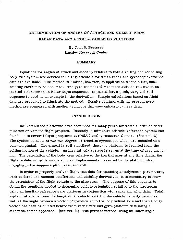
Equations for angles of attack and sideslip relative to both a rolling and nonrolling body axis system are derived for a flight vehicle for which radar and gyroscopic-attitude data are available. The method is limited, however, to application where a flat, nonrotating earth may be assumed. The gyro considered measures attitude relative to an inertial reference in an Euler angle sequence. In particular, a pitch, yaw, and roll sequence is used as an example in the derivation. Sample calculations based on flight data are presented to illustrate the method. Results obtained with the present gyro method are compared with another technique that uses onboard-camera data.
‘7. Key Words (Suggested by Authou 18. Distribution Statement
Radar Gyroscope Unclassified - Unlimited
Angle of attack and sideslip
19. Security a&f. (of thii report) 20. Security Classif. (of this page) 21. No. of Pages
Unclassified Unclassified 20
*For sale by the Nationel Technical Information Service, Springfield, Virginia 22151
22. Price’
$3.00
-
DETERMINATION OF ANGLES OF ATTACK AND SIDESLIP FROM
RADAR DATA AND A ROLL-STABILIZED PLATFORM
By John S. Preisser Langley Research Center
SUMMARY
Equations for angles of attack and sideslip relative to both a rolling and nonrolling body axis system are derived for a flight vehicle for which radar and gyroscopic-attitude data are available. The method is limited, however, to application where a flat, non- rotating earth may be assumed. The gyro considered measures attitude relative to an inertial reference in an Euler angle sequence. In particular, a pitch, yaw, and roll sequence is used as an example in the derivation. Sample calculations based on flight data are presented to illustrate the method. Results obtained with the present gyro method are compared with another technique that uses onboard-camera data.
INTRODUCTION
Roll-stabilized platforms have been used for many years for vehicle-attitude deter- mination on various flight projects. Recently, a miniature attitude-reference system has found use in several flight programs at NASA Langley Research Center. (See ref. 1.) The system consists of two two-degree-of-freedom gyroscopes which are mounted on a common gimbal. The gimbal is roll stabilized; thus, the platform is isolated from the rolling motion of the vehicle. An inertial axis system is set up at the time of gyro uncag- ing. The orientation of the body axes relative to the inertial axes at any time during the flight is determined from the angular displacements measured by the platform after uncaging in the sequence pitch, yaw, and roll.
In order to properly analyze flight-test data for obtaining aerodynamic parameters, such as force and moment coefficients and stability derivatives, it is necessary to know the orientation of the flight vehicle to the airstream. The purpose of this paper is to obtain the equations needed to determine vehicle orientation relative to the airstream using an inertial-reference gyro platform in conjunction with radar and wind data. Total angle of attack between the longitudinal vehicle axis and the vehicle velocity vector as well as the angle between a vector perpendicular to the longitudinal axis and the velocity vector has been calculated before from radar data and gyro-platform data using a direction-cosine approach. (S ee ref. 2.) The present method, using an Euler angle
B
C
J
K
L,L’
u,v,w
u’,v’,w’
Uf ,Vf ,Wf
V
KY,Z
X’,Y’,Z
2
SYMBOLS
transformation matrix between earth-fixed axis system and lift-off body axis system
transformation matrix between earth-fixed axis system and free-stream- velocity axis system
transformation matrix between inertial axis system and lift-off body axis system
transformation matrix between inertial axis system and body axis system
transformation matrices between free-stream-velocity axis system and body axis system
components of free-stream velocity along X-, Y-, and Z-axis, respectively
components of free-stream velocity along X’-, Y’-, and Z’-axis, respectively (u’ = u)
components-of free-stream velocity along Xf-, Yf-, and Zf-axis, respectively
free-stream velocity (vehicle velocity relative to the surrounding air; see appendix)
body axis system (a ‘right-handed, orthogonal axis system); X is along the longitudinal axis of the vehicle; Y is coincident with the gyro pitch axis at the time of gyro uncaging; Z is coincident with the gyro yaw axis and in the vertical plane at the time of gyro uncaging
nonrolling body axis system; X’ = X; Y’ forms a right-handed, orthogonal axis system with X’ and Z’; the X’Z’-plane is the vertical plane when l)‘=O
approach, facilitates the correction of all gyro errors, misalinements, and drift prior to vehicle lift-off and also provides the components of the total angle of attack - angles of attack and sideslip. Angles of attack and sideslip are calculated for both a nonrolling and a rolling body axis system. The method, however, is limited to applications where a flat, nonrotating earth may be assumed.
,

xr,Yf Jf
~w,~w&J
a
a'
B
P'
r a,oJe,o
yP
YY
~g,~g,@g
earth-fixed axis system; Xf is, north; Yf is west; Zf is up
axis system alined with free-stream velocity; Xw is along the velocity vector; Yw forms a right-handed, orthogonal axis system with Xw and Z,; Zw is in the vertical plane with a component up along the local vertical
angle of attack, a = tan- l(w/u)
angle of attack relative to nonrolling body axes, a’ = tan- l(w’/u’)
sideslip angle, p = sin- l(v/V)
sideslip angle relative to nonrolling body axes, p’ = sin-1($/V)
azimuth and elevation launch angles (launcher settings)
free-stream flight-path angle in pitch, rp = tan -lkf/(q
free-stream flight-path angle in yaw, yy = tan- l (-vfpf)
gyro-platform Euler angles measured from inertial reference in the sequence pitch, yaw, and roll, respectively
Euler angles measured from free-stream-velocity axes to vehicle-body axes in the sequence roll, yaw, and pitch, respectively
Euler angles measured from free-stream-velocity axes to vehicle-body axes in the sequence yaw, pitch, and roll, respectively
Subscripts:
0 at vehicle lift-off
u at gyro uncaging

Matrix notation:
Cl square matrix
0 column matrix
A dot over a symbol indicates differentiation with respect to time.
ANALYSIS
Angles of attack and sideslip for a vehicle in flight can be derived from a knowledge of time histories of range, azimuth, and elevation of the vehicle, the local wind velocity, and the vehicle attitude relative to some defined inertial reference. In addition, these angles can be derived free from any gyro errors that occur prior to the start of the flight test. It will be shown that to accomplish this requires defining five separate axis systems and five axis transformations. The axis systems are an earth-fixed axis system, the gyro inertial axis system, the flight-vehicle axis system at lift-off, an axis system defined by the free-stream-velocity vector, and a body axis system. All axis systems used in this report are right handed.
Transformation 1
The transformation equations relating the lift-off attitude of the flight vehicle to- an earth-fixed axis system are
where
4
II
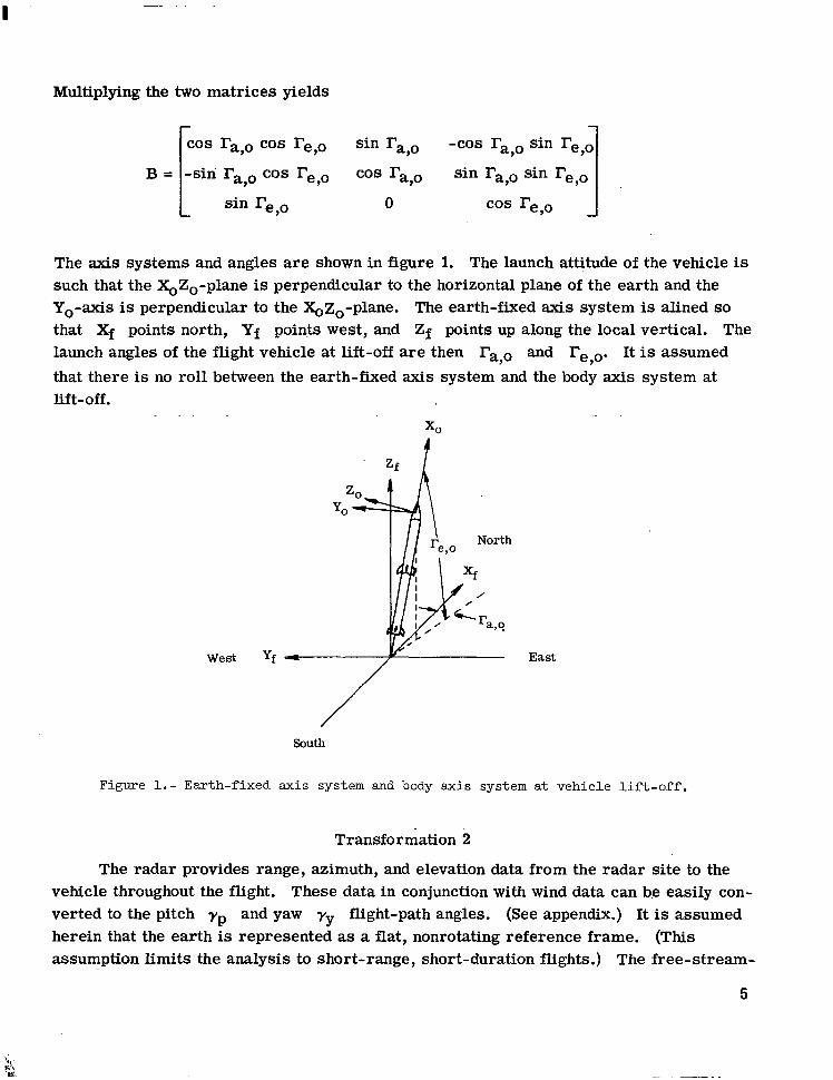
Multiplying the two matrices yields
B=
COS ra,o COS re,o sin ra,o -cos ra,o sin re,o
-sin ra,o cos re,o cos ra,o sin l?a,o sin re,o sin re,o 0 cos re,o I
The axis systems and angles are shown in figure 1. The launch attitude of the vehicle is such that the XoZo-plane is perpendicular to the horizontal plane of the earth and the Yo-axis is perpendicular to the XoZo-plane. The earth-fixed axis system is alined so that Xf points north, Yf points west, and Zf points up along the local vertical. The launch angles of the flight vehicle at lift-off are then 17a,o and l?e,o. It is assumed
that there lift-off.
is no roll between the earth-fixed axis system and the body axis system at
West yf East
Figure l.- Earth-fixed axis system and body axis system at vehicle lift-off.
Transformation 2
The radar provides range, azimuth, and elevation data from the radar site to the vehicle throughout the flight. These data in conjunction with wind data can be easily con- verted to the pitch yp and yaw ry flight-path angles. (See appendix.) It is assumed herein that the earth is represented as a flat, nonrotating reference frame. (This assumption limits the analysis to short-range, short-duration flights.) The free-stream-
5
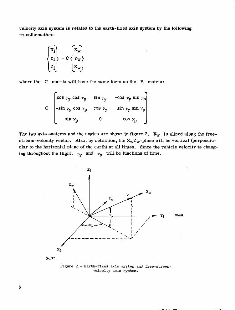
velocity axis system is related to the earth-fixed axis system by the following transformation:
xr
(1 Yf =c
Z f
where the C matrix will have the same form as the B matrix:
cos
1
yy cos yp sin y Y -cos yy sin yp
c= -sin yy cos yp cm Yy
1 sin yy sin yp
L sin yp 0 cos y P J
The two axis systems and the angles are shown in figure 2. Xw is alined along the free+ stream-velocity vector. Also, by definition, the X,Z,-plane will be vertical (perpendic-l ular to the horizontal plane of the earth) at all times. Since the vehicle velocity is chang- ing throughout the flight, yy and yp will be functions of time.
Zf
/- yf West /
/
North
Figure 2.- Earth-fixed axis system and free-stream- Velocity axis system.
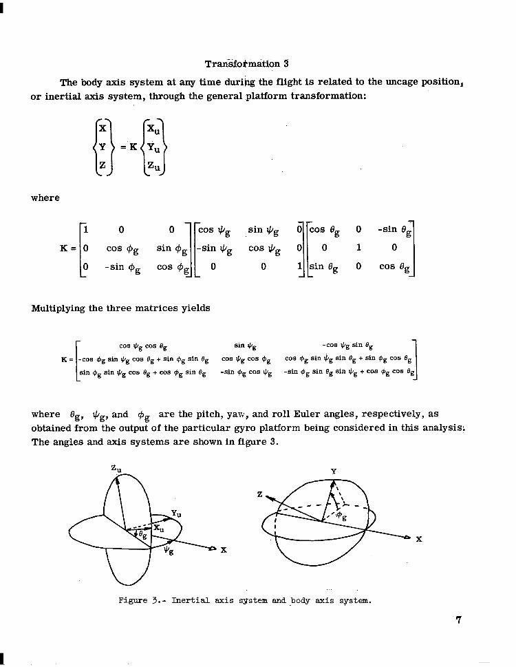
Transformation 3
The body axis system at any time during the flight is related to the uncage position, or inertial axis system, through the general :platform transformation:
where
K=
Multiplying the three matrices yields
co9 eg co9 eg sin J/g -cos eg sin Og
eg sin I& co8 Og + sin C#J~ sin Bg COB *g co9 9, co9 qbg sin J/g sin Bg + sin eg co9 eg
sin I& co8 eg + co8 eg sin eg -sin $J~ co6 eg I
-sin I#I~ sin eg sin GI, + co8 eg co8 eg
where Bg, I$~, and Gg are the pitch, yaw, and roll Euler angles, respectively, as obtained from the output of the particular gyro platform being considered in this analysis\ The angles and axis systems are shown in figure 3.
Figure 3.- Inertial axis sgstem and body axis system.

Transformation 4
For various reasons, a gyro platform might not have zero readings on all three axes at the time of vehicle lift-off. For some mission requirements, the gyro might have been uncaged while the vehicle was in one position and launched when the vehicle was in ! another. (See ref. 3.) In addition, since a roll-stabilized platform provides a true iner- tial reference in space, the earth’s rotation will cause readings on the gyro while the ‘,,
vehicle is still on the earth. The magnitude of these readings will depend on any time delay between uncaging and lift-off. AIso, residual gyro readings due to gimbal misalinet- ment and uncage errors may occur. From whatever source, the initial readings can be accounted for simply by referencing them back to some effective zero position. If the
initial gyro readings at lift-off are 13~,~, +g,o, and +g,o, the lift-off position may be considered to have been arrived at by going through the Euler angle sequence 8g,o, qg,o, and $g,o that originated at some effective zero position. The effective zero position is
the true inertial axis system. The transformation equations can be written as
x, XU
11 I) YO =i Y,
zo Zl.l
where the J matrix has the same form as the K matrix. (It is assumed that the gyro platform is mounted so that it is alined with the vehicle axis.)
03s eg,o cos eg,o sin tig,o -cos *g,o sin 8g,o
$g,o sin J/g,o cos Og,o + sin Cg,o sin eg,o cos eg,o cos @g,o co9 q5,,, sin J/g,o sin Og,o + sin @g,o co6 eg,o
sin *g,o cos Og,o + co6 #g,o sin eg,o -sin @g,o cos 3/g,o 1 -sin qbg,o sin *g,o sin eg,o + cos $J~,~ cos eg,o
Now, by using the four sets of matrix-transformation equations just defined, the free-stream-velocity axis system can be directly related to the body axis system. That
is,
where J -1 and B-l are the inverse.matrices of J and B, respectively. (For orthogonal transformations, such as those being considered here, the inverse matrix is
8
identical to the transpose matrix and can be obtained by interchanging the rows and the columns of the matrix array.)
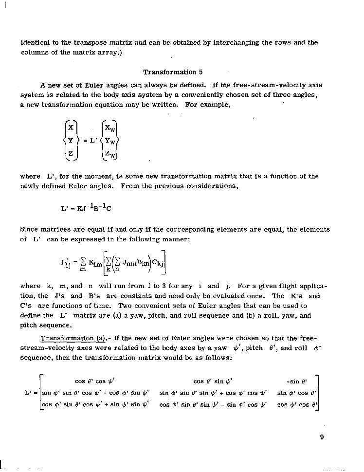
Transformation 5
A new set of Euler angles can always be defined. If the free-stream-velocity axis system is related to the body axis system by a conveniently chosen set of three angles,
‘a new transformation equation may be written. For example,
where L’, for the moment, is some new transformation matrix that is a function of the newly defined Euler angles. From the previous considerations,
L’ = KJ-$+C
Since matrices are equal if and only if the corresponding elements are equal, the elements of L’ can be expressed in the following manner:
where k, m, and n will run from 1 to 3 for any i and j. For a given flight applica- tion, the J’s and B’s are constants and need only be evaluated once. The K’s and C’s are functions of time. Two convenient sets of Euler angles that can be used to define the L’ matrix are (a) a yaw, pitch, and roll sequence and (b) a roll, yaw, and pitch sequence.
Transformation (a).- If the new set of Euler angles were chosen so that the free- stream-velocity axes were related to the body axes by a yaw Ic/‘, pitch O’, and roll c$’ sequence, then the transformation matrix would be as follows:
[
cos 8’ cos lg cos 8’ sin $’ -sin 8’
L’ = sin c$’ sin 8’ cos I&’ - c0S $’ sin *’ sin C#I’ sin 8’ sin *’ + cos f$’ cos $J’ sin C#J’ cos 8’ cos C#I’ sin 8’ cos *’ + sin c$’ sin Ic/’ cos $I’ sin 8’ sin I)’ - sin +’ cos $2 cos I#)’ cos 8’
9
-
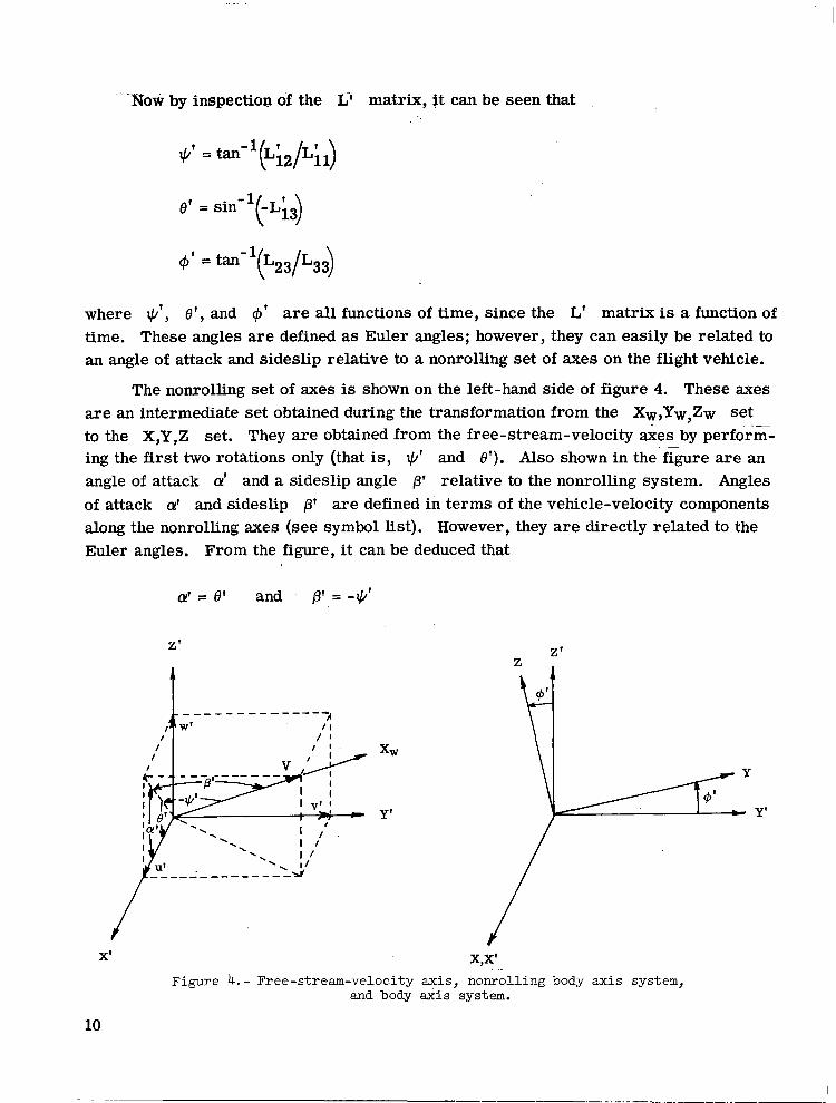
-Now by inspection of the Lf matrix, It can be seen that
3/’ = tan-1(L;2/L;S
8’ = sin -1 t ) -Li3
6 = tan- ‘(L231L33)
where +’ , 8’, and $’ are all functions of time, since the L’ matrix is a function of time. These angles are defined as Euler angles; however, they can easily be related to an angle of attack and sideslip relative to a nonrolling set of axes on the flight vehicle.
The nonrolling set of axes is shown on the left-hand side of figure 4. These axes are an intermediate set obtained during the transformation from the X,,Yw,Zw set to the X,Y,Z set. They are obtained from the free-stream-velocity &es by perform- ing the first two rotations only (that is, +’ and 6’). Also shown in the figure are an angle of attack a’ and a sideslip angle 8’ relative to the nonrolling system. Angles of attack a’ and sideslip /3’ are defined in terms of the vehicle-velocity components along the nonrolling axes (see symbol list). However, they are directly related to the Euler angles. From the figure, it can be deduced that
a’ = 8’ and 0 = -I&’
X’ X,X’
Figure 4.- Free-stream-velocity axis, nonrolling body axis system, and body s&s system.
10
------ -.-.-. .-.... -.-.- . ..-.-------. _- ---. ~.
F’inalI~the body axes are’obtained by rolling an Bmount,, @‘, from the no~nrolling set. This axis system is shown in the right-hand side of figure 4.
Transformation (b).- By using a transformation different than the previous one, an a and a fi measured from the body axes can be obtained. The desired angles can be obtained hy using a roll, yaw, and pitch sequence from the free-stream-velocity axes to the body axes. The transformation equations can be written as
X XW
!I (1 Y =L Y,
Z ZW
where’ L now takes the form
cos * cos 8
[ cos $I sin * cos 8 + sin + sin 8 sin $ sin * cos 8 - cos @ sin 8
L= -sin * cos I& cos @ sin $ cos Q
cos t) sin e cos C$ sin + sin e - sin r$ cos 8 sin + sin 8 sin @ + cos @ cos 1 8
By’inspection-of the L matrix, it can be seen that
Ic/ = sin-l -Lzl ( >
8 = ti3.C1(Lgl/Lll)
@ = taf1(L23/L22)
Now L=L’ = XJ-lB-lC, SO that Lij = Lij and the formula previously derived for LI. 11
can be used again here.
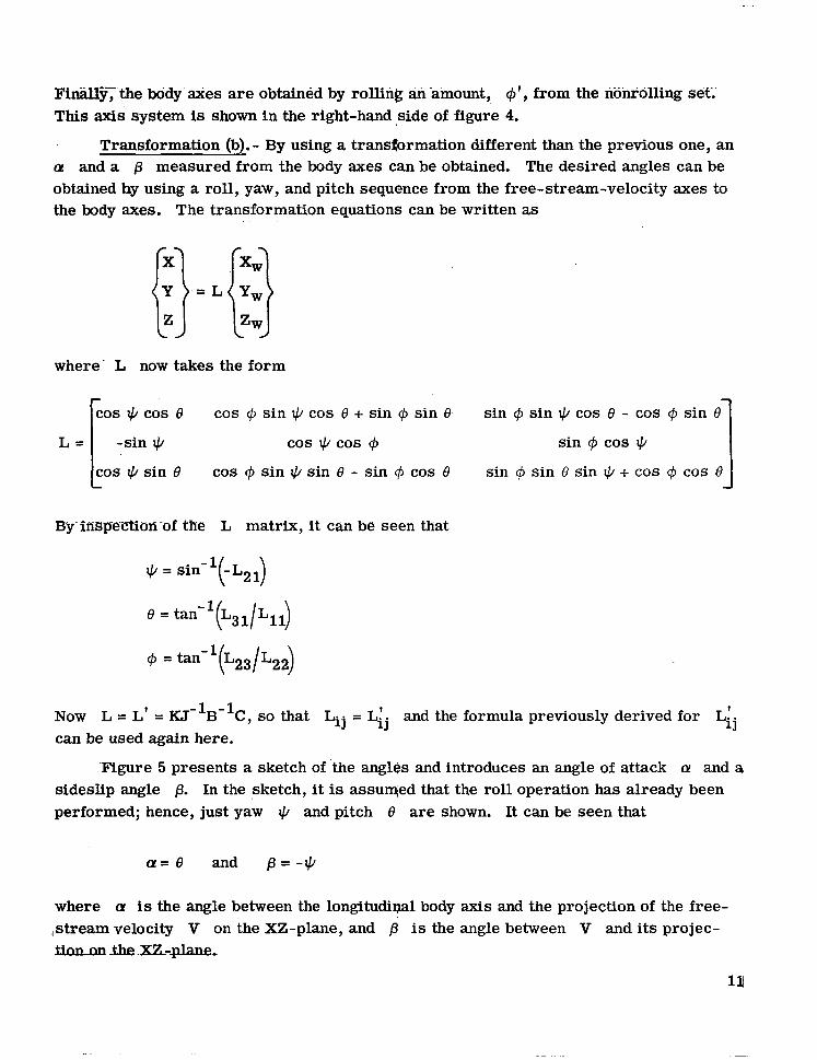
‘Figure 5 presents a sketch of ‘the angles and introduces an angle of attack cy and a sideslip angle 8. In the sketch, it is assumed that the roll operation has already been performed; hence, just yaw + and pitch 8 are shown. It can be seen that
a= 8 and @=-Ic/
where a is the angle between the longitudinal body axis and the projection of the free- ,stream velocity V on the XZ-plane, and B is the angle between V and its projec- tinnnn_the.XZ-plane,
Z
Figure 5. - Free-stream-velocity axis and body &is system.
It should be note? that the Lij equation is general and therefore can be applied to any other gyro system with any Euler angle set. All that is required is that the general platform transformation be known for use in the J and K matrices. The equations for angles of attack and sideslip will remain the same.
APPLICATION OF TECHNIQUE
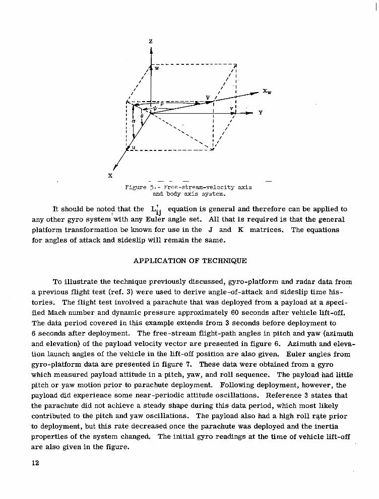
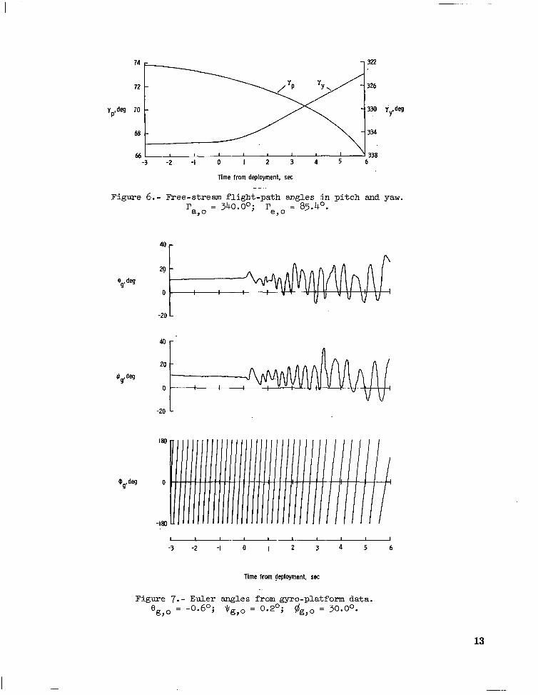
To illustrate the technique previously discussed, gyro-platform and radar data from a previous flight test (ref. 3) were used to derive angle-of-attack and sideslip time his- tories. The flight test involved a parachute that was deployed from a payload at a speci- fied Mach.number and dynamic pressure approximately 60 seconds after vehicle lift-off. The data period covered in this example extends from 3 seconds before deployment to 6 seconds after deployment. The free-stream flight-path angles in pitch and yaw (azimuth and elevation) of the payload velocity vector are presented in figure 6. Azimuth and eleva- tion launch angles of the vehicle in the lift-off position are also given. Euler angles from gyro-platform data are presented in figure 7. These data were obtained from a gyro which measured payload attitude in a pitch, yaw, and roll sequence. The payload had littIe pitch or yaw motion prior to parachute deployment. Following deployment, however, the payload did experience some near-periodic attitude oscillations. Reference 3 states that the parachute did not achieve a steady shape during this data period, which most likely contributed to the pitch and yaw oscillations. The payload also had a high roll rate prior to deployment, but this rate decreased once the parachute was deployed and the inertia properties of the system changed. The initial gyro readings at the time of vehicle lift-off are also given in the figure.
12
Time from deployment, SK
Figure 6.- Free-stream flight-path angles in pitch and yaw. r
a90 = 340.0O; re o = 85.4’.
,
-3 -2 -I 0 I 2 3 4 5 6
Time from @kyment, set
Figure 7.- Euler angles from gyro-platform data. 8 g,. = -0.6~; $g,o = 0.2~; #g,o = 30.0°.
13
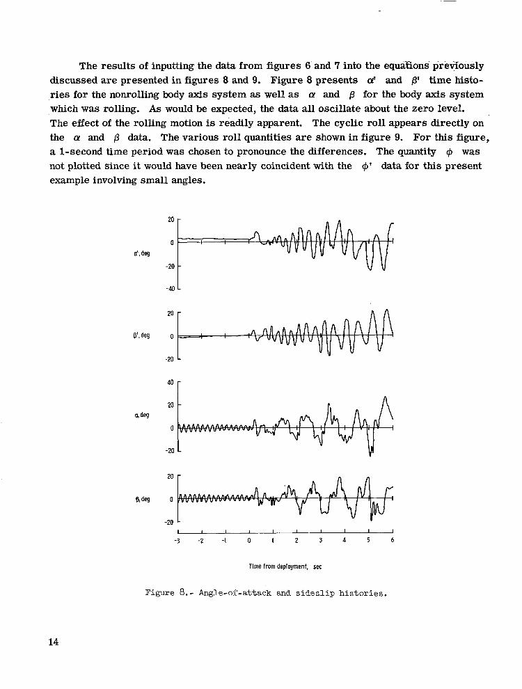
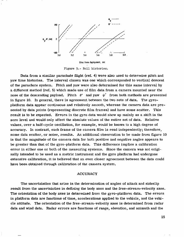
The results of inputting the data from figures G’and 7 into the equaxons previously discussed are presented in figures 8 and 9. Figure 8 presents a’ and p’ time histo- ries for the nonrolling body axis system as well as a and fl for the body axis system which was rolling. As would be expected, the data all oscillate about the zero level. -The effect of the rolling motion is readily apparent. The cyclic roll appears directly on the CY and /3 data. The various roll quantities are shown in figure 9. For this figure, a l-second time period was chosen to pronounce the differences. The quantity $I was not plotted since it would have been nearly coincident with the c$’ data for this present example involving small angles.
a’,@
V.deg
20 -
0 I
-20 -
-40 L
I 1 I I 1 I I 1 I 1
-3 -2 -I 0 I 2 3 4 5 6
Time from deployment, set
Figure 8.- Angle-of-attack and sideslip histories.
14
5.0 5.2 5.4 5.6 5.8 6.0
Time from deployment, WC
Figure 9.- Roll histories.
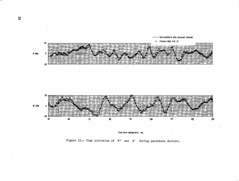
Data from a similar parachute flight (ref. 4) were also used to determine pitch and yaw time histories. The interval chosen was one which corresponded to vertical descent of the parachute system. Pitch and yaw were also determined for this same interval by a different method (ref. 5) which made use of film data from a camera mounted near the nose of the descending payload. Pitch 8’ and yaw $J’ from both methods are presented in figure 10. In general, there is agreement between the two sets of data. The gyro- platform data appear continuous and relatively smooth, whereas the camera data are pre- sented by data points (representing discrete film frames) and have some scatter. This result is to be expected. Errors in the gyro data would show up mainly as a shift in the zero level and would only affect the absolute values of the entire set of data. Relative values, over a half-cycle oscillation, for example, would be known to a high degree of accuracy. In contrast, each frame of the camera film is read independently; therefore, some data scatter, or noise, results. An additional observation to be made from figure 10 is that the magnitude of the camera data for both positive and negative angles appears to be greater than that of the gyro-platform data. This difference implies a calibration error in either one or both of the measuring systems. Since the camera was not origi- nally intended to be used as a metric instrument and the gyro platform had undergone extensive calibration, it is believed that an even closer agreement between the data could have been obtained through calibration of the camera system.
ACCURACY
The uncertainties that arise in the determination of angles of attack and sideslip result from the uncertainties in defining the body axes and the free-stream-velocity axes. The orientation of the body axes is determined from the gyro-platform data. The errors in platform data are functions of time, accelerations applied to the vehicle, and the vehi- cle attitude. The orientation of the free-stream-velocity axes is determined from radar data and wind data. Radar errors are functions of range, elevation, and azimuth and the
15
e’, deg
S’.deg
- Gyro-platform data (present method)
o Camera data (ref. 5) ZU
0
-20
20
0
-20
Time from deployment, set
Figure lO.- Time histories of 8' and $' during parachute descent.
time rate-of change of these parameters. Hence, an error analysis must proceed from a given flight profile, where the body motions and radar parameters are known.
An unpublished detailed error analysis for an attitude-reference system like the one described in this report has been performed. For the parachute flight tests pre- viously described, the results indicate errors in gyro pitch, yaw, and roll to be between lo and 2O for the time periods shown in figures 6 to 10. In addition to these gyro errors, there is an uncertainty of 0.25 deg/min because the earth’s rotation has not been accounted for. Radar errors have been estimated from references 3 and 4 to be approximately 0.5O
in ry and rp. Hence, the calculated angles of attack and sideslip are estimated to be lmown within k.30 for the examples illustrated in this report.
CONCLUDING REMARKS
Equations have been derived to determine angle of attack and sideslip for both a nonrolling and rolling axis system for a flight vehicle which is radar tracked and which carries onboard a gyroscopic-attitude system. The method is limited, however, to appli- cations where a flat, nonrotating earth may be assumed. Specifically, a pitch, yaw, roll Euler angle gyro was chosen as the example to be worked out. However, the results can easily be applied to other gyro systems if the general platform transformation is known. Sample calculations were m&de, and the results compared well with an independent method of attitude determination.
Langley Research Center, National Aeronautics and Space Administration,
Hampton, Va., February 14, 1972.
17
I -
APPENDIX
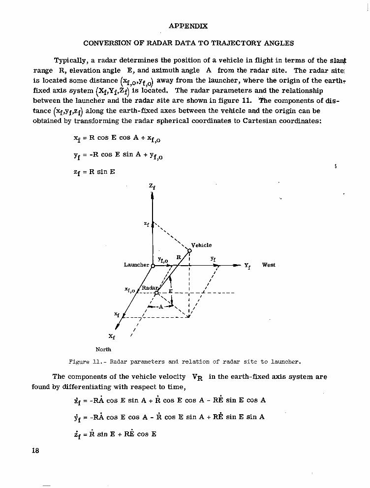
CONVERSION OF RADAR DATA TO TRAJECTORY ANGLES
Typically, a radar determines the position of a vehicle in flight in terms of the sla# range R, elevation angle E, and azimuth angle A from the radar site. The radar site; is located some distance (q,o,yf o) away from the launcher, where the origin of the earth? fixed axis system (Xf,Yf,Zf) is ldcated. The radar parameters and the relationship between the launcher and the radar site are shown in figure 11. ‘The components of dis- tance (xf,yf,zf) along the earth-fixed axes between the vehicle and the origin can be obtained by transforming the radar spherical coordinates to Cartesian coordinates:
xf = R cos E cos A + xfo
Yf = -R cos E sin A + yf o ,
f zf = R sin E
West
North
Figure 11.- Radar parameters and relation of radar site to launcher.
The components of the vehicle velocity VR in the earth-fixed axis system are found by differentiating with respect to time,
Sf = -G cos E sin A + R cos E cos A - RI? sin E cos A
if = -ld cos E cos A - R cos E sin A + RI? sin E sin A
if = k sin E + Ri cos E
18
APPENDIX - Concluded
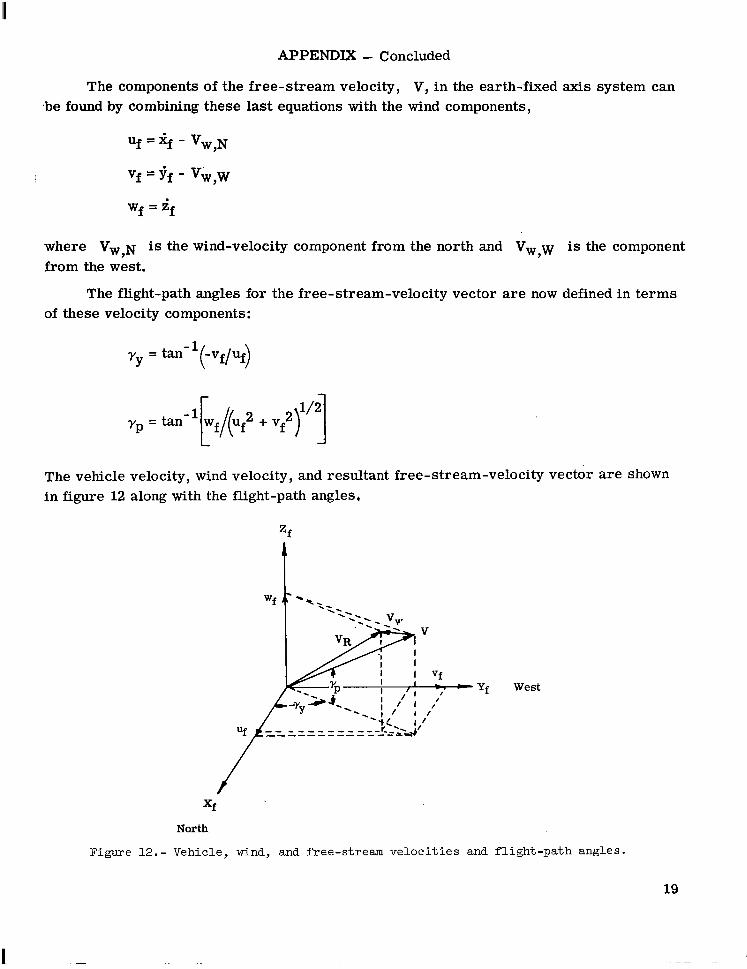
The components of the free-stream velocity, V, in the earth-fixed axis system can ,be found by combining these last equations with the wind components,
uf=%-vw,N
Vf = I+ - vw,w
Wf = if
where Vw,~ is the wind-velocity component from the north and V,,w is the component from the west.
The flight-path angles for the free-stream-velocity vector are now defined in terms of these velocity components:
yY = tan-l -Vf uf
(0
rp = tan -‘E/q + g,““1
The vehicle velocity, wind velocity, and resultant free-stream-velocity vector are shown in figure 12 along with the flight-path angles,
- Yf West
Figure 12.- Vehicle, wind, and free-stream velocities and flight-path angles.
19
1 -
REFERENCES
1. McFall, John C., Jr.; and Murrow, Harold N.: Parachute Testing at Altitudes Between 30 and 90 Kilometers. J. Spacecraft Rockets (Eng. Notes), vol. 4, no. 6, June 1967, pp. 796-798.
2. Marcou, Rene J.; and Pruneau, Paul N.: Aspect of a Rocket From Gyroscopic Data. AFCRL-66-349, U.S. Air Force, 1966. (Available from DDC as AD 635 014.)
3. Preisser, John S.; and Eckstrom, Clinton V.: Flight Test of a 30-Foot-Nominal- Diameter Cross Parachute Deployed at a Mach Number of 1.57 and a Dynamic Pressure of 9.7 Pounds Per Square Foot. NASA TM X-1542, 1968.
4. Preisser, John S.; and Eckstrom, Clinton V.: Flight Test of a 40-Foot-Nominal- Diameter Disk-Gap-Band Parachute Deployed at a Mach Number of 1.91 and a Dynamic Pressure of 11.6 Pounds Per Square Foot. NASA TM X-1575, 1968.
5. Bendura, Richard J.; Henning, Allen B.; and Smith, Robert E., Jr.: Vehicle Attitude Determination With a Single Gnboard Camera. NASA TN D-4359, 1968.
20 NASA-Langley, 1972 - 27 L-7886 j

NATIONAL AERONAUTICS AND SPACE ADMISTRATION
WASHINGTON. D.C. 20546 POSTAGE AND FEI
OFFICIAL BUSINESS NATlONAL AERONAU ^__^_ _- . . . ..^ ‘--
PENALTY FOR PRlVATE USE s300 FIRST CU-- ==I” 330 MAIL
“The aerotzautical and space activities of the Unites States shall be conducted so as to contribute . , . to the expansion of human knowl- edge of phenomena in the atmosphere and space. The Administration shaIl provide for the widest practicable and appropriate disreminatiofz of information concerning its activities and the results thereof.”
-NATIONAL AERONAUTICS AND SPACE ACT OF 1958
NASA SCIENTIFIC AND TECHNICAL PUBLICATIQN~S
TECHNICAL REPORTS: Scientific and technical information considered important, complete, and a lasting contribution to existing knowledge.
TECHNICAL NOTES: Information less broad in scope but nevertheless of importance as a, contribution to existing kn&&dge.
TECHNICAL MEMORANDUMS: Information receiving limited distribution because of preliminary data, security classifica- tion, or other reasons. ?
CONTRACTOR REPORTS: Siientific and technical information generated under a NASA contract or grant and considered an important contribution to existing knowledge.
TECHNICAL TRANSLATIONS: Information published in a foreign language considered to merit NASA distribution in English.
SPECIAL PUBLICATIONS: Information derived from or of value to NASA activities. Publications include conference proceedings, monographs, data compilations, handbooks, sourcebooks, and special bibliographies.
TECHNOLOGY UTiLIZATION PUBLICATIONS: Information on t&hnology used by NASA that may be of particular interest in commercial and.other non-aerospace applications. Publications include Tech Briefs, Technology Utilization Reports and Technology Surveys.
Details on the availability ot these publications may be obtained from:
SCIENTIFIC AND TECHNICAL INFORMATION OFFICE
NATIONAL AERON‘AUTICS AND SPACE ADMINISTRATION Washington, D.C. ~0546