national fire equipment ltd. backflow parts - december - 2010
TRANSCRIPT


National Fire Equipment Ltd.Backflow Parts - December - 2010
Table Of ContentsBackflow Replacement Parts
Ames Double Check Backflow Assembly PartsAmes�Series�2000SS�2.5"���6"�&�2000SE�6"���8" 1Ames�Colt�Series�C200�(DC)�&�C300�(DCD)�2.5"���10"� 2
Ames Reduced Pressure Backflow Assembly PartsAmes Series 4000SS (RP) & 5000SS (RPD) 2.5" - 6" 3Ames Series 4000SS (RP) & 5000SS (RPD) 2.5" - 6" Relief Valve Parts 4Ames Series C400 (RP) & C500 (RPD) 2.5" - 4" 5Ames Series C400 (RP) & C500 (RPD) 2.5" - 4" Relief Valve Parts 6
Apollo Double Check Backflow Assembly PartsApollo Series 40-100 .75" - 2" 7Apollo Series 40-100 .75" - 2" Valve Exploded View 8Apollo Series 40-100 2.5" - 4" 9Apollo Series 40-100 2.5" - 4" Valve Exploded View 10Apollo Series 40-100 6" - 10" 11Apollo Series 40-100 6" - 10" Valve Exploded View 12Apollo Series 4S-100 2.5" - 6" Parts & Valve Exploded View 13Apollo Series 4S-100 8" & 10" 14Apollo Series 4S-100 8" & 10" Valve Exploded View 15
Apollo Reduced Pressure Backflow Assembly PartsApollo�Series�40�200�.25"���2" 16Apollo�Series�40�200�.25"���2"�Valve�Exploded�View 17Apollo�Series�40�200�2.5"���6" 18Apollo�Series�40�200�2.5"���6"�Valve�Exploded�View 19Apollo�Series�40�200�8"�&�10" 20Apollo�Series�40�200�8"�&�10"�Valve�Exploded�View 21Apollo�Series�40�200�2.5"���10"�Relief�Valve�Parts 22Apollo�Series�40�200�2.5"���10"�Relief�Valve�Parts�Exploded�View 23
Febco Double Check Backflow Assembly PartsFebco�Series�805Y�.75"���2" 24Febco�Series�805Y�.75"���2"�Valve�Exploded�View 25Febco�Series�805YD�(DC)�&�806YD�(DCD)�2.5"���10"�Repair�Parts 26Febco�Series�805YD�(DC)�&�806YD�(DCD)�2.5"���10"�Repair�Kits 27Febco�Series�805YD�(DC)�&�806YD�(DCD)�2.5"���10"�Parts�List�&�Valve�Exploded�View 28Febco�Series�850�&�850U�.5"���2"�Parts�List 29Febco�Series�850�&�850U�.5"���2"�Repair�Kits 30Febco�Series�850�&�850U�.5"���2"�Valve�Exploded�View 31Febco�Series�850�(DC)�&�856�(DCD)�Parts�List�&�Valve�Exploded�View 32Febco�Series�870�(DC)�&�876�(DCD)�Parts�List�&�Valve�Exploded�View 33
Febco Reduced Pressure Backflow Assembly PartsFebco�Series�825Y�&�YA�.75"���2"�Parts�List 34Febco�Series�825Y�&�YA�.75"���2"�Repair�Kits�&�Valve�Exploded�View 35Febco�Series�860�&�860U�.75"���2"�Parts�&�Valve�Exploded�View 36Febco�Series�860�&�860U�.75"���2"�Check�&�Relief�Valve�Repair�Kits 37Febco�Series�860�&�860U�.75"���2"�Check�&�Relief�Valve�Repair�Kits�Continued 38Febco�Series�860�&�880V�2.5"���10"�Parts�List 39Febco�Series�860�&�880V�2.5"���10"�Parts�List�Continued 40Febco�Series�860�&�880V�2.5"���10"�Valve�Exploded�View 41Febco�Series�880V�2.5"���10"�Valve�Exploded�View 42Febco�Series�860�&�880V�2.5"���10"�Repair�Kits 43Febco�Series�860�&�880V�2.5"���10"�Repair�Kits�Continued 44
Watts Double Check Backflow Assembly Parts Watts�Series�007�.5"���2"�Parts�&�Valve�Exploded�View 45Watts�Series�757�&�757N�(DC�&�DCD)�2.5"���10"�Parts�&�Valve�Exploded�View 46
I

National Fire Equipment Ltd.Backflow Parts - December - 2010
Table Of ContentsBackflow Replacement Parts
Watts Double Check Backflow Assembly Parts (Continued)Watts�Series�774�(DC�&�DCD)�2.5"���6"�Parts�&�Valve�Exploded�View 47Watts�Series�774�(DC�&�DCD)�8"���12"�Parts�&�Valve�Exploded�View 48Watts�Series�709�(DC�&�DCD)�.75"���2"�Parts�&�Valve�Exploded�View 49Watts�Series�709�(DC�&�DCD)�2.5"���10"�Parts�&�Valve�Exploded�View 50
Watts Reduced Pressure Backflow Assembly PartsWatts�Series�009�.25"���2"�Parts�&�Valve�Exploded�View 51Watts�Series�009�.25"���2"�Relief�Valve�Parts�&�Valve�Exploded�View 52Watts�Series�909�.75"���2"�Parts�&�Valve�Exploded�View 53Watts�Series�909�.75"���2"�Relief�Valve�Parts�&�Valve�Exploded�View 54Watts�Series�909�(RP�&�RPD)�2.5"���10"�Parts�&�Valve�Exploded�View 55Watts�Series�909�(RP�&�RPD)�2.5"���10"�Relief�Valve�Parts�&�Valve�Exploded�View 56Watts�Series�957�(RP�&�RPD)�2.5"���10"�Parts�&�Valve�Exploded�View 57Watts�Series�957�(RP�&�RPD)�2.5"���10"�Relief�Valve�Parts�&�Valve�Exploded�View 58
Wilkins/Zurn Double Check Backflow Assembly PartsWilkins�Series�350�.75"���1"� 59Wilkins�Series�350�.75"���1"�Valve�Exploded�View 60Wilkins�Series�350�1.25"���2"� 61Wilkins�Series�350�1.25"���2"�Exploded�View 62Wilkins�Series�350A�(2.5"���10")�&�350�(4"���12")� 63Wilkins�Series�350A�(2.5"���10")�&�350�(4"���12")�Valve�Exploded�View 64Wilkins�Series�950XL�.75"���2"� 65Wilkins�Series�950XL�.75"���2"�Valve�Exploded�View 66Wilkins�Series�950�2.5"���12" 67Wilkins�Series�950�2.5"���12"�Valve�Exploded�View 68
Wilkins/Zurn Reduced Pressure Backflow Assembly PartsWilkins�Series�375�.75"���1" 69Wilkins�Series�375�.75"���1"�Valve�Exploded�View 70Wilkins�Series�375�1.25"���2" 71Wilkins�Series�375�1.25"���2"�Repair�Kits�&�Valve�Exploded�View 72Wilkins�Series�375A�(2.5"���10")�&�375�(4"���12")� 73Wilkins�Series�375A�(2.5"���10")�&�375�(4"���12")�Valve�Exploded�View 74Wilkins�Series�375A�&�375�(2.5"���12")�Relief�Valve�Parts�&�Exploded�View 75Wilkins�Series�975XL�.75"���1" 76Wilkins�Series�975XL�.75"���1"�Valve�Exploded�View�&�Repair�Kits�(Con't) 77Wilkins�Series�975�2.5"���10" 78Wilkins�Series�975�2.5"���10"�Valve�Exploded�View 79Wilkins�Series�975�2.5"���10"�Relief�Valve�Parts�Exploded�View 80
Backflow Prevention Assembly Test KitsWilkins�Model�TG�5���5�Valve�Test�Kit�Assembly 81Watts�Model�TK�99E�Test�Kit�Assembly 82Watts�Model�TK�9A�Test�Kit�Assembly 83Watts�Model�TK�7�Series�7,�709,�&�007�Test�Kit�Assembly 84Mid�West�Mode;�845�5�Test�Kit�Assembly 85
Backflow Prevention Assembly AccessoriesMid�West�Instrument�Test�Kit�Accessories 86Mid�West�Instrument�Test�Kit�Accessories�Continued 87Wilkins�Model�QT�SET�Quick�Test�Fittings 88Apollo�40�200�Series�Bleed�Valve/Sight�Tube 89Apollo�Model�AGD�&�AGD4A�Series�Air�Gap�Drains 90Watts�Air�Gap�Drains,�Elbows�&�Test�Cocks� 91Watts�Air�Gap�Drains,�Elbows�&�Test�Cocks�Continued 92Wilkins�Model�AG�Air�Gap�Adapter�Fitting 93
Wilkins Series 300AR Backflow Replacement ProgramWilkins�Series�300AR�Product�Information�Literature 94���95Wilkins�Series�300AR�Series�Order�Form 96
II

Please Read Prior to Installation:1. Before installing any Ames backflow assembly, flush the line
thoroughly to remove all debris, chips and other foreign
objects. Failure to do so may make the assembly inoperable.
2. The Ames 2000SS and 3000SS may be placed in any posi-
tion as long as the flow indicator arrow in the assembly is
pointed in the direction of water flow, and the local water
authority has approved the installation configuration. ASSE
(American Society of Sanitary Engineers) has approved
these assemblies for either horizontal or vertical installation.
3. Allow sufficient clearance around the installed assembly to
conduct testing, servicing, and inspection. Allow a minimum
of 12" from the flood level to the bottom of the assembly.
4. If double check or double check detector assembly is installed
in a vault or pit, be sure proper drainage is available. If suffi-
cient drainage is not available a cross-connection may occur.
Attention Installer: After installation, please leave thisInstruction Sheet for occupant’s information.
2
Outdoor Installation
Installation Instructions
Vertical Installation
Detailed Parts Listing
Parts Table #1Ames Part No.
Item # Description Qty 21/2" (65mm) 3" (80mm) 4" (100mm) 6"SS (150mm) 6"SE (150mm) 8"SE (200mm)
1. #1 Cam-Check 1 7015559 7015559 7015559 7015564 7015559 70155642. #2 Cam-Check 1 7015560 7015560 7015560 7015565 7015560 70155653. #1 Cam-Check O-ring 1 7015333 7015333 7015333 7013280 7015333 70132804. #2 Cam-Check O-ring 1 7013229 7013229 7013229 7013281 7013229 70132815. Cover Plate 1 7013241 7013241 7013241 7013289 7013474 70132896. Ball Valve 2 A000449 A000449 A000449 A000449 A000449 A0004497. Groove Coupler 1 7013194 7013194 7013194 7013287 7013194 70132878. Groove Coupler Gasket 1 7013248 7013248 7013248 7013308 7013248 70133089. Ball Valve (Cover) 1 A603134 A063134 A603134 7013034 7013034 7013034
Indoor Installation
5
9
2413
87
66
AMES SERIES 2000SS/SE D.C. REPLACEMENT PARTS LIST
1

ITEM NO. PART DESCRIPTION 21/2" (65mm) 3" (80mm) 4" (100mm) 6" (150mm) 8" (200mm) 10" (250mm)
1 FIRST CHECK MODULE (RED SILICONE)a 7018111 7018111 7018111 7018114 7018117 7018399
2 SECOND CHECK MODULE (RED SILICONE) 7018113 7018113 7018113 7018116 7018119 7018400
3 CHECK MODULE O-RING 7017861 7017861 7017861 7017910 7013301 7018352
4 ELASTOMER SHUTOFF DISC (RED SILICONE) 7017855 7017855 7017855 7017903 7017928 7018348
5 GROOVED CLEVIS PIN KIT(CONTAINS: “E” CLIP & CLEVIS PIN) 7018126 7018126 7018126 7018127 7018127 7018412
5 PER PACK
6 CLOSURE SLEEVE TEST-COCK 7018152 7018152 7018152 7018153 7018153 7018153WITH O-RING #3
7 CLOSURE SLEEVE 7017880 7017880 7017880 7017882 7017884 7017886
8 SLEEVE O-RING or GASKET (2 REQ’D) 7017896 7017896 7017896 7017921 7017944 7018339
NS CHECK REPAIR KIT (CONTAINS: 7018123 7018123 7018123 7018124 7018125 7018414O-RING, RED SILICONE SHUTOFF
DISC & “E” CLIP)
NS TEST COCK, .50 FPT X FPT 7018394 7018394 7018394 N/A N/A N/AWITH NIPPLE
NS TEST COCK, .75 FPT X FPT N/A N/A N/A 7018395 7018395 7018395WITH NIPPLE
NS "E" CLIP 7017870 7017870 7017870 7017821 7017821 7017974
NS GROOVE COUPLER (SHUTOFF) 7017994 7017995 7018147 7018148 7018149 7018070
NS GROOVE COUPLER GASKET 7018882 7018883 7018884 7013248 7013308 N/A
NS SLEEVE COUPLER ASSEMBLY N/A N/A N/A N/A 7018122 7018413
NS O-RING, #3 TEST COCK 7017897 7017897 7017897 7017897 7017897 7017897
NS STAINLESS STEEL CHECK RETAINER 7018408 7018408 7018408 7018409 7018410 7018411
6. Closure Sleeve Test Cock with O-ring
7. Closure Sleeve
5. E-clip and Clevis Pin
4. Elastomer Shutoff Disc
2. Second Check Module
8. Sleeve O-ring
3. Check Module O-ring
1. First Check Module
Replacement Parts Listing
RP/IS-A-C200/C300 0904 EDP#7018382 ©Ames Fire & Waterworks 2009
www.amesfirewater.com
A Division of Watts Water Technologies, Inc. USA: Backflow- 1427 N. Market Blvd • Suite #9 • Sacramento, CA 95834 • T: 916-928-0123 • F: 916-928-9333
Control Valves- 18550 Hansen Road • Houston, TX 77075 • T: 713-943-0688 • F: 713-944-9445
Canada: 5435 North Service Rd. • Burlington, ONT. L7L 5H7• T: 905-332-4090 • F: 905-332-7068
CHECK REPAIR KIT
AMES COLT SERIES C200 & C300 D.C. REPLACEMENT PARTS LIST
2

3
NOTE: Ames assemblies require minimum maintenance. Allassemblies must be retested once maintenance has beenperformed. Before servicing be certain shutoff valves are closed.
Removing Cam-Checks1. Shut down water system and lock out system if possible.
Slowly open all ball valves to relieve air and water pressure.
Loosen bolts on groove coupler and remove groove coupler
and cover plate from valve body.
2. Remove #1 Cam-Check Assembly by using your hands to
unscrew (turn counter-clockwise) Cam-Check and remove
through top access port. Do not use Cam Arm as a han-dle to unscrew Cam-Check. If Cam-Check cannot be
loosened by hand, insert a long screwdriver between valve
body and Cam-Check (see figure 3). Gently apply pressure
against the Cam-Check until loosened. Finish unscrewing by
hand. Unscrew #2 Cam-Check (turn counter-clockwise) by
placing a long screwdriver across lugs and applying pres-
sure to loosen #2 Cam-Check. Finish unscrewing by hand.
3. To clean #1 Cam-Check (except 21/2" – 4" (65-100mm) DC
Check), locate the Cam Arm opening stud on the outlet
flange of the valve assembly. Slide the Cam Arm over the
stud with the check threads facing downward (figure 5A).
Tighten 1/4" nut on stud to secure cam bar. Slowly pull the
assembly outward to open check allowing exposure of the
seat and clapper contact area for cleaning. To clean #2
Cam-Check, lift Cam Arm and hold in open position. Raise
clapper so that the end of the Cam Arm rests between roller
and clapper (figure 5B). Thoroughly clean the seat area and
clapper sealing surfaces of both Cam-Checks. Rinse Cam-
Checks and O-rings thoroughly. Inspect seats, clapper seal-
ing surfaces, Cam Arms, and O-rings for damage, nicks,
and debris. If not damaged, gently close the clapper. If dam-
aged, install a new Cam-Check assembly and/or O-ring or
shutoff disc.
4. Before reinstallation of check assembly, thoroughly clean
O-ring groove and lubricate with F.D.A. approved lubricant.
Insert and thread #2 Cam-Check first and then #1 Cam-
Check. #2 Cam-Check should be tightened by inserting a
long screwdriver between lugs to tighten firmly (see figure 2).
Do not over tighten. Tighten #1 Cam-Check firmly by hand
only. Replace cover plate, clean groove coupler gasket and
groove. Replace groove coupler. Close ball valves.
Repressurize and bleed air from all test cocks.
Detailed Parts Listing
#1 Cam Check 21/2" – 6" (65-150mm) RP (Short Cam)
Figure 4
Maintenance Instructions
Figure 3Figure 2
Parts Table #1Ames Part No.
Item # Description Qty 21/2" (65mm) 3" (80mm) 4" (100mm) 6"SS (150mm)
1. #1 Cam-Check 1 7015561 7015561 7015561 70155662. #2 Cam-Check 1 7015560 7015560 7015560 70155653. #1 Cam-Check O-ring 1 7015333 7015333 7015333 70132804. #2 Cam-Check O-ring 1 7013229 7013229 7013229 70132815. Cover Plate 1 7013241 7013241 7013241 70132896. Ball Valve 2 7014668 7014668 7014668 70146687. Groove Coupler 1 7013194 7013194 7013194 70132878. Groove Coupler Gasket 1 7013248 7013248 7013248 70133089. Relief Valve 1 7013354 7013354 7013354 7013354
(Complete assembly)10. Relief Valve Hose 1 7013343 7013343 7013343 701334311. Relief Valve Body O-ring 1 A400084 A400084 A400084 A40008412. Ball Valve (Cover) 1 A603134 A603134 A603134 7013034
#1 CamCheck
#2 CamCheck
Screwdriver
AB
C
O-ring Seal& Groove
O-ring Seal& Groove
Seat Clapper
Roller
SpringCam Arm
#2 Cam Check DC & RP
Lug
Seat
O-ring Seal & Groove
Clapper
6" OnlyRoller
Cam ArmSpring
Figure 5A
Cam Bar Open Pin
Valve Outlet FlangeThreaded Stud on Flange
6" (150mm) 1st Check DC6" (150mm) 2nd Check DC & RP
Figure 5B
CleaningPosition
Flow1
2
3
4
56
78
9
1110
12
Figure 1
AMES SERIES 4000SS & 5000SS R.P. REPLACEMENT PARTS LIST
3

1. The relief valve may be serviced while on or off the backflow
preventer valve.
2. Note: Do not use a pipe wrench to remove the relief valveassembly from the backflow preventer.
3. Shut down water system.
Relief Valve Disassembly1. Disconnect the relief valve hose from the elbow in the bot-
tom flange cover at the swivel hose connection. Do not
remove the elbow.
2. If the valve is to be removed from the backflow preventer
for service, place a screw driver blade or flat bar across
the edges of (2) of the hex head screws in the bottom
flange cover and turn counter-clockwise to loosen the
relief valve assembly. (see Figure 2)
3. Remove the (4) bottom bolts from the bottom of the relief
valve assembly with a 5/16" socket or open-end wrench.
Remove the bottom flange cover.
4. Remove the piston assembly & sleeve from the relief valve
body by placing your index fingers through the slots in the
side of the body and pressing down on the top of the disc
retainer in the top of the piston assembly. (See Figure 7.)
5. Pull the piston assembly free of the body by grasping the
sleeve and pulling down.
6. Grip the sleeve and the piston assembly by the head of the
hex head bolt. Pull up on the sleeve to extend the
diaphragm. Slide the sleeve (Part #7013340) completely off
of the diaphragm and inspect the diaphragm for tears, holes
or excessive wrinkles. If the diaphragm is damaged, order a
new piston/diaphragm assembly.
Relief Valve Reassembly1. Thoroughly clean all inside surfaces of the relief valve body.
2. Inspect the relief valve body seat surface located at the
top edge of the (3) discharge slots near the top of the
body by rubbing the end of the index finger around the
entire seat surface; access the seat surface through the
slots or the bottom of the body. The seat must be free of
nicks. If nicks are discovered, remove the body & install a
new relief valve assembly.
3. Position the diaphragm on the piston assembly so that it is
facing up as shown in Figure 8.
4. Now fold the top (ribbed) edge of the diaphragm inward,
grasp the sleeve with the ribbed edge up and slide the
sleeve down over the piston assembly as shown in Figure 8.
5. While still holding the sleeve, slide it up over the diaphragm
and, using your thumb & index finger, position the bead of
the diaphragm so that it wraps over the outside of the rib on
the top of the sleeve so that the sleeve is held by the
diaphragm. Now place the piston assembly on a flat, firm
surface with diaphragm facing up as shown in Figure 9.
6. Cup your hand slightly to form an air trap and force the
sleeve down over the piston assembly with a rapid slap
(hard) on the open end of the diaphragm with your cupped
hand. The trapped air in the diaphragm will force the
diaphragm between the inside of the sleeve and the outside
of the piston. Ensure that the diaphragm is fully seated by
running the end of a dull “butter” knife in the formed
diaphragm. If diaphragm is wrinkled, repeat previous step.
7. Slide the piston assembly and sleeve into the relief valve
body with the hex head bolt entering the flanged end of the
body first. Slide the piston assembly in until the diaphragm
lip is smoothly seated in the machined groove in the
flanged end of the body. By running your index finger
around the outside of the diaphragm bead, you will ensure
it is seated smoothly.
8. Position the bottom flange cover on the bottom of the
relief valve body and secure by hand tightening the (4) bot-
tom bolts.
9. Now tighten the (4) bottom bolts to approximately 15 ft.-lbs.
with a 5/16" socket or open-end wrench.
10. Reattach the relief valve hose to the elbow in the bottom
flange cover.
4
Relief Valve Service Instructions
Parts Table #2Item # Part Description Qty Ames Part No.
21. Relief Valve Body 1 701333722.* Rubber Shut-Off Disc. 1 701333023.* Piston Diaphragm Assembly 1 701335224. Hex Head Bolt 1 701332625. Disc. Retainer 1 701332826. Sleeve 1 701334027. Bottom Bolt 1 701254528. Bottom Flange (w/St. Elbow) 1 701333929. Elbow St 90 3/8 1 A40360930.* O-Ring Disk 2 701332731. RV Spring 1 7013368Not Shown - RV Rubber Kit (Includes * Items and Body O-Ring.) 7018897
Figure 9
Figure 6 Figure 7
Figure 8
Relief Valve
31
21
2224
30
25
26
2829
23
27
RV Rubber Kit
4
AMES SERIES 4000SS & 5000SS R.P. PARTS - RELIEF VALVE

6
Replacement Parts Listing
ITEM DESCRIPTION ORDERING ORDERING ORDERINGNO. CODE 21⁄2" (65MM) CODE 3" (80MM) CODE 4" (100MM)1. First Check Module (EPDM) 7018112 7018112 7018112
1. First Check Module (Red Silicone) 7018760 7018760 7018760
2. Second Check Module (a) (EPDM) 7018120 7018120 7018120
2. Second Check Module (a) (Red Silicone) 7018764 7018764 7018764
3. O-ring, Check Module 7017861 7017861 7017861
4. Disc, Elastomer Shut Off (EPDM) 7018329 7018329 7018329
4. Disc, Elastomer Shut Off (Red Silicone) 7017855 7017855 7017855
5. Grooved Clevis Pin Kit(Contains: “E” Clip & Clevis Pin - 5 per pack) 7018126 7018126 7018126
6. Closure Sleeve Test-Cock with O-ring 7018152 7018152 7018152
7. Closure Sleeve 7017881 7017881 7017881
8. Sleeve O-ring or Gasket (2 req’d) 7017896 7017896 7017896
9. Relief Valve Assembly (Hose included) 7018107 7018107 7018107
NS Check Repair Kit(Contains: O-ring, Shutoff EPDM Disc & “E” clip) 7018391 7018391 7018391
NS Check Repair Kit(Contains: O-ring, Shutoff Red Silicone Disc & “E” clip) 7018123 7018123 7018123
NS “E” Clip 7017870 7017870 7017870
NS Test Cock, .50 FPT x FPT with Nipple 7018394 7018394 7018394
NS Test Cock, .75 FPT x FPT with Nipple N/A N/A N/A
NS Groove Coupler (Shutoff) 7017994 7017995 7018147
NS Groove Coupler Gasket 7018882 7018883 7018884
NS Sleeve Coupler Assembly N/A N/A N/A
NS Air Gap Drain 7018367 7018367 7018367
NS Splash Guard (only) 7018894 7018894 7018894
NS O-ring, #3 Test Cock 7017897 7017897 7017897
NS Stainless Steel Check Retainer 7018408 7018408 7018408
ITEM DESCRIPTION ORDERING ORDERING ORDERINGNO. CODE 6" (150MM) CODE 8" (200MM) CODE 10" (250MM)1. First Check Module (EPDM) 7018115 — —
1. First Check Module (Red Silicone) 7018761 7018118 7018401
2. Second Check Module (a) (EPDM) 7018121 — —
2. Second Check Module (a) (Red Silicone) 7018765 7018119 7018402
3. O-ring, Check Module 7017910 7013301 7018352
4. Disc, Elastomer Shut Off (EPDM) 7017903 — —
4. Disc, Elastomer Shut Off (Red Silicone) 7017903 7017928 7018348
5. Grooved Clevis Pin Kit 7018127 7018127 7018412
(Contains: “E” Clip & Clevis Pin - 5 per pack)
6. Closure Sleeve Test-Cock with O-ring 7018153 7018153 7018153
7. Closure Sleeve 7017883 7017885 7017887
8. Sleeve O-ring or Gasket (2 req’d) 7017921 7017944 7018339
9. Relief Valve Assembly (Hose included) 7018107 7018107 7018107
NS Check Repair Kit
(Contains: O-ring, Shutoff EPDM Disc & “E” clip) 7018392 — —
NS Check Repair Kit
(Contains: O-ring, Shutoff Red Silicone Disc & “E” clip) 7018124 7018125 7018414
NS “E” Clip 7017821 7017821 7017974
NS Test Cock, .50 FPT x FPT with Nipple N/A N/A N/A
NS Test Cock, .75 FPT x FPT with Nipple 7018395 7018395 7018395
NS Groove Coupler (Shutoff) 7018148 7018149 N/A
NS Groove Coupler Gasket 7013248 7013308 N/A
NS Sleeve Coupler Assembly N/A 7018122 7018413
NS Air Gap Drain 7018367 7018367 7018367
NS Splash Guard (only) 7018894 7018894 7018894
NS O-ring, #3 Test Cock 7017897 7017897 7017897
NS Stainless Steel Check Retainer 7018409 7018410 7018411
1
3
9
87
2
5
4
6
Check Repair Kit
Check Repair Kit
Check Repair Kit
Check Repair Kit
5
AMES COLT SERIES C400 & C500 R.P. REPLACEMENT PARTS LIST

7
Troubleshooting Guide
Difficulty Possible Cause Correction
#1 check is fouled Remove and clean #1 check
Relief valve discharges water Relief valve does not properly close Service relief valvewhile system is not flowing
Municipal water pressure is fluctuating Install check valve upstreamof backflow assembly
Fouled relief valve seat Service relief valve
Relief valve does not Incorrectly installed diaphragm Remove diaphragm and shut off properly correctly install
Damaged rubber surface on piston Replace with new piston
Damaged or plugged pressure hose Repair or replace hose.
Relief Valve Replacement Parts Listing
ITEM DESCRIPTION ORDERINGNO. CODE1. Relief Valve Assembly 7018107
2. Diaphragm, RV 7017809
3. Spring, RV 7013368
4. Spider Bushing, RV 7017811
5. Piston Assembly, RV* 7018227
6. Body, RV 7018889
7. Hose & Cover Plate Assembly 7018228
8. Screw, Cover RV 7017822
9. O-ring, Inlet coupler 7017826
10. ‘E’ Clip (5 per pack) 7017870
NS Sensing Elbow 7018888
ITEM DESCRIPTION USE FOR ORDERINGNO. CODENS Hose (1/2"x20") 21⁄2" & 3 M400, M500 7018890
NS Hose (1/2"x24") 21⁄2" & 3 M400 N & Z 7018891
NS Hose (1/2"x30") 6 M400, 2.5, 3, 4 M500, 701889221⁄2", 3, 4 M400 N & Z,21⁄2", 3, 4 M500 N & Z,21⁄2" & 3 M500 N & Z BFG
NS Hose (1/2"x36") 8 & 10 M400, 70188936, 8, 10 M400 N & Z,4 & 6 M400BFG N & Z,6, 8, 10 M500,6, 8, 10 M500 N & Z4 & 6 M500BFG N & Z
*includes shutoff disc
1
6
7
2
9
10
4
3
5
8
AMES COLT SERIES C400 & C500 R.P. PARTS - RELIEF VALVE
6

15
40-100Double Check Backflow Preventer
ITEM NO. DESCRIPTION QUANTITY PART NO.
3/4" & 1" 1-1/4", 1-1/2", 2" 1 Body 1 Consult Consult
Factory Factory
2 Cap 2 F-310805* F-311505** n/s Plug 2 K-301200* K301900** 3 Spring 2 A-170000 A-170100
4 Poppet 2 K-336200 K-336700
5 Seat Disc 2 D-250300 D-250800
6 Seat Retainer 2 D-249900 D-250900
7 Screw 2 B-175000 B-175000
8 Cap O-Ring 2 D-250000 D-251000
9 Test Cock 3 78-257-01 78-258-01
10 Check Seat 2 L-486400 L-486600
11 Check O-Ring 2 D-227400 D-256500
Repair Kits Major Repair Kit
(4 (2), 5 (2), 6 (2), 7 (2), 8 (2), 40-004-A5 40-007-A5
10 (2), 11 (2)), n/s packet lube
Check Valve Repair Kit
(4, 5, 6, 7, 8, 10, 11), n/s packet lube 40-004-A2 40-007-A2
Rubber Repair Kit
(5 (2), 8 (2), 11 (2)), n/s packet lube 40-004-A6 40-007-A6
Replaceable Seat Kit
(10 (2), 11 (2)), n/s packet lube 40-004-A8 40-007-A8
AccessoriesDouble Check Valve Test Kit 40-200-TKU (3-Valve)
40-200-TK5U (5-Valve)
* 1/8” NPT plub needed for units without top mounted test cocks.
** 1/4” NPT plug needed for units without top mounted test cocks.
Repair Kits
APOLLO SERIES 40-100 D.C. REPLACEMENT PARTS
7

16
Parts Listing 3/4" - 2" (Bronze) Top Entry
7
6
5
4
10
11
1
9
2
3
8
Outlet Shut-Off Valve
Inlet Shut-Off Valve
APOLLO SERIES 40-100 D.C. REPLACEMENT PARTS
8

19
DCVParts List
ITEM NO. DESCRIPTION QUANTITY PART NO. 2-1/2" 3" 4" 1 Shut-Off Valve (OS&Y) 2 W-6789-00 W-6790-00 W-6824-00
1 Shut-Off Valve (NRS) 2 W-6785-00 W-6786-00 W-6743-00
1 Shut-Off Valve (Ball) 2 6Q-209-01 6Q-200-01 6Q-20A-01
2 Brass Nipple 1 K-3406-00 K-3406-00 K-3406-00
3 Test Cock 1 70-103-01 70-103-01 70-103-01
7 Body 1 Q-4526-19 Q-4527-19 Q-4534-19
10 C.V. Seat O-Ring 2 D-2576-00 D-2567-00 D-2573-00
11 C.V. Seat 2 L-4637-05 L-4637-05 L-4640-05
12 C.V. Stem 2 G-3239-06 G-3239-00 G-3242-00
13 C.V. Stem O-Ring 2 D-2561-00 D-2561-00 D-2561-00
14 Retainer Nut 2 C-1756-00 C-1756-00 C-1756-00
15 Retainer Washer 2 E-2199-00 E-2199-00 E-2204-00
16 C.V. Seat Disc 2 D-2560-00 D-2560-00 D-2572-00
17 Seat Disc Holder 2 F-3000-05 F-3000-05 F-3001-05
18 1st Check Spring 1 A-1741-00 A-1741-00 A-1744-00
19 2nd Check Spring 1 A-1741-00 A-1741-00 A-1744-00
20 Spring Retainer 2 E-2198-05 E-2198-05 E-2202-05
21 Jam Nut 2 C-1589-05 C-1589-05 C-1589-05
22 Cap O-Ring 2 D-2566-00 D-2566-00 D-2574-00
23 C.V. Cap 2 Q-4530-19 Q-4530-19 Q-4533-19
24 Cap Bolt 12 B-1797-00 B-1797-00 B-1801-00
25 Test Cock 3 70-803-10 70-803-10 70-803-10
Repair Kits1st Check Valve Repair Kit 40-009-02 40-009-02 40-00A-02
(12, 13, 14, 15, 16, 17, 18, 20, 21, 22), n/s packet lube
Seat Repair Kit 40-009-03 40-009-03 40-00A-03
(10, 11, 22), n/s packet lube
Rubber Repair Kit 40-009-04 40-009-04 40-00A-04
2 each (10, 13, 16, 22), n/s packet lube
Repair Kits
APOLLO SERIES 40-100 D.C. REPLACEMENT PARTS
9

18
Parts Listing 2-1/2" - 10" (Ductile Iron)
2 1/2" - 3" - 4" DCV
APOLLO SERIES 40-100 D.C. REPLACEMENT PARTS
10

21
DCVParts List
ITEM NO. DESCRIPTION QUANTITY PART NO. 6" 8" 10"
1 Shut-Off Valve (OS&Y) 2 W-6825-00 W-6826-00 W-6859-00
1 Shut-Off Valve (NRS) 2 W-6744-00 W-6827-00 W-6858-00
1 Shut-Off Valve (Ball) 2 6Q-20C-01 6Q-20E-01 N/A
2 Brass Nipple 1 K-3412-40 K-3412-00 K-3412-00
3 Test Cock 1 70-104-10 70-104-10 70-104-10
6A Stud 2 N/A N/A B-2036-00
7 Body 1 Consult Factory Consult Factory Consult Factory
7A Body 1 Consult Factory Consult Factory Consult Factory
10 C.V. Seat O-Ring 2 D-2576-00 D-2589-00 D-2588-00
11 C.V. Seat 2 L-4644-05 L-4653-05 L-4759-05
12 C.V. Stem 2 G-3246-00 G-3273-00 G-3305-00
13 C.V. Stem O-Ring 2 D-2578-00 D-2587-00 D-2587-00
14 Retainer Nut/Bolt *** C-1760-00 B-1754-00 B-1754-00
15 Retainer Washer 2 E-2205-00 E-2208-00 E-2229-00
16 C.V. Seat Disc 2 D-2575-00 D-2586-00 D-2649-00
17 Seat Disc Holder 2 F-3002-05 F-3008-05 F-3019-05
18 1st Check Spring 1 A-1746-00 A-1748-00 A-1779-00
19 2nd Check Spring 1 A-1746-00 A-1748-00 A-1779-00
20 Spring Retainer 2 E-2203-05 E-2207-05 E-2228-05
21 Jam Nut 2 C-1706-00 C-1763-00 C-1763-00
22 Cap O-Ring 2 D-2577-00 D-2588-00 D-2651-00
23 C.V. Cap 2 Q-4537-19 Q-4545-19 Q-4574-19
24 Cap Bolt **** B-1800-00 B-1690-00 B-1881-00
25 Test Cock 3 70-804-10 70-804-10 70-804-10
N/S Seat Bolt 12 N/A N/A B184900
*** 6" QTY = 2 / 8" & 10" QTY = 8
**** 6" QTY = 12 / 8" & 10" QTY = 24
Repair KitsCheck Valve Repair Kit 40-00C-02 40-00E-02 40-00G-02
(12, 13, 14, 15, 16, 17, 18, 20, 21, 22), n/s packet lube
Seat Repair Kit 40-00C-03 40-00E-03 40-00G-03
(10, 11, 22), n/s packet lube
Rubber Repair Kit 40-00C-04 40-00E-04 40-00G-04
2 each (10, 13, 16, 22), n/s packet lube
Repair Kits
APOLLO SERIES 40-100 D.C. REPLACEMENT PARTS
11

20
6" - 8" - 10" DCV
APOLLO SERIES 40-100 D.C. REPLACEMENT PARTS
12

�
Double Check Backflow Preventer2 ½” – 6”
ITEM # DESCRIPTION QTY. PART # ITEM # DESCRIPTION QTY. PART #
������������������������������� ������������ ���� ��� ��������������������������� ����������� ���� ���������������������������� ���� ������������ ���� ��� ���������������������������� ����������� ���� ������������������������� !���� "�������������������������� ���� ��� ����������������������#"���� ����������$ ���% ���������������������������&��'��� ������������ ���� ��� ������������������������(�� "�� ����������� ��%� ������������������������'�)���*+",� �����������- ��%� ��� ������������������������#��� �����������. ���� ����������������������������� ���� ������������ ���� ��� ���������������������� ����� ����������/ ��%� ���������������������������)���*+",� �����������- ��%� ��� �����������������������#"�� ����������0 ���� ����������������������������� ""���� ������������. ���� ������%������������������� ""���#��� ������������. ���� ��������������������������1$2�"��� ������������. ���� ������������������������3���)�*� �����������& ���% ���
REPAIR KITS FOR 2 ½” – 6”����'�4�"!���������0���5.��"�6���������� 7����*���8��8���6��9(((((((((((((((((((((((((((((((((�� ��% �����++����������0���5���"�6���������� 7����*���8��8��8���8���6���9((((((((((((((((((((((((((((((�� ��% ��
REPAIR KITS FOR 2 ½” – 6”
APOLLO SERIES 4S-100 D.C. REPLACEMENT PARTS
13

Double Check Backflow Preventer 8” & 10” DC
ITEM # DESCRIPTION QUANTITY PART # �
����������������%�����������������������������%�����������������������������%�
�:2�;���� �'����� "�� !���#�" ��#���
�*���*����&��'���
������)��<,�:2�;���� �'�:2�=���"��
=���> �'�-�������3���)�*�# ���� �����*�� ""������*�=���
*������ ��� "��� ""���#���
���'����*� *������ ��������
���������� �����"�������������������������#"����
��������������� "�������#���
����������� ����:2�#"��?2�#"��
�������������������������������������������������������������
��� ��� ���� ���� ���@ ���� �%�. ���� ���. ���� ���� �%�� ���- ���� ����� ��� ���0 ���� ��� ���% ���$ ���� ���/ ���� ���. ���� ���. ���� ��� ���� ���� ���� ���� ���� ���& �%�� ���) ���% ���$ ��%� ���/ ���� ���� �%�� ���$ ��%� ���� ���� ���� ���� ���> ���� ���� �%�� ���0 ���� ���0 ���� ���
REPAIR KITS FOR 8” & 10”����'�4�"!���������0���5.��"�6������*������6��� ��8���������������'�!�"!�9(((((((((((�� ��$ ����++����������0���5���"�6���������� 7����*���8���8���6���9((((((((((((((((((((((((((((((((((((((�� ��$ ��
��
REPAIR KITS FOR 8” & 10”
APOLLO SERIES 4S-100 D.C. REPLACEMENT PARTS
14

%
APOLLO SERIES 4S-00 D.C. REPLACEMENT PARTS
15

12
40-200Reduced Pressure Principle Backflow Preventer
ITEM NO. DESCRIPTION QUANTITY PART NO.
1/4", 3/8", 1/2" 3/4" & 1" 1 1/4", 1 1/2", 2" 1 Body 1 Consult Consult Consult Factory Factory Factory 2 R.V. Cover 1 F301705 F298205 F298505 3 Cap 2 F323105 F310805 F311505 4 R.V. Bushing 1 I450715 I424015 I425715 5 R.V. Stem 1 G329600 G321200 G321300 6 Diaphragm Plate 1 E222200 D250600 D251600 7 Poppet 2 K340900 K336200 K336700 8 R.V. Diaphragm 1 D263200 D250500 D251500 9 R.V. Seat Disc 1 D263100 D282900 D251400 10 Check Seat Disc 2 D263000 D250300 D250800 11 Stem O-Ring 1 D262800 D250200 D251300 12 Bushing O-Ring 1 D262900 D250100 D251200 13 Check Cap O-Ring 2 D204600 D250000 D251000 14 R.V. Spring 1 A179500 A169800 A170200 15 1st Check Spring 1 A179700 A169900 A170300 16 2nd Check Spring 1 A179400 A170000 A170100 17 Hex Head Bolt 6(*4) (**7) B179300 B175100 B175400 18 Screw 2 B183700 B175000 B175000 19 Screw 1 B174900 B174900 B175300 20 Screw 1 B183700 B174800 B175300 21 Retaining Washer 2 E222300 D249900 D250900 22 Retaining Washer 1 E222400 D249800 D249900 23 Test Cock 4 7829001 7829001 7829101 24 Check Seat 2 L515200 L486400 L486600 25 Check O-Ring 2 D308600 D227400 D256500 26 R.V. Seat 1 L515300 L486300 L486700 27 R.V. O-Ring 1 D308700 D216800 D227400 O-Ring Lubricant 1 I901600 I901600 I901600Repair Kits***Major Repair Kit4, 5, 6, 7 (2), 8, 9, 10 (2), 11, 12,13 (2), 14, 18 (2), 19, 20, 21 (2), 22, 40003A1 40004A1 40007A124 (2), 25 (2), 26, 27
Check Valve Repair Kit7, 10, 13, 18, 21, 24, 25 40003A2 40004A2 40007A2
Relief Valve Repair Kit4, 5, 6, 8, 9, 11, 12, 14, 19, 20, 22, 40003A3 40004A3 40007A326, 27
Rubber Repair Kit8, 9, 10 (2), 11, 12, 13 (2), 25 (2), 27 40003A4 40004A4 40007A4
Replaceable Seat Kit24 (2), 25 (2), 26, 27 40003A7 40004A7 40007A7
AccessoriesAir Gap Drain AGD4012 AGD401 40200X1
Seat Removal Tool 40000SRT 40000SRT 40000SRT
Reduced Pressure Backflow Preventer Test Kit 40200TKU, 40200TK5U, or 40200TKRC (All Sizes) * 1/4", 3/8" & 1/2" SIZES ONLY ** 1-1/4", 1-1/2" & 2" SIZES ONLY *** For repair kits without replaceable seat components, replace part number suffix designation “A” with “O”. Example: Major Repair Kit part number 4000401
Repair Kits***
APOLLO SERIES 40-200 R.P. REPLACEMENT PARTS LIST
16

11
VII PARTS LISTING 1/4" - 2" (Bronze)
12
3
456
7
8
9
10
1112
13
23
14
15
16
17
18
19
20
21
22
24
25
26
27
Inlet and Outlet Shut-Off Valves40-20X-TX
Size 1/4” 3/8” 1/2” 3/4” 1” 1-1/4” 1-1/2” 2”Inlet Shut-Off Valve (pictured) 7B80101 7B80201 7B80301 7B80401 7B80501 7B80699A 7B80799A 7B80899AInlet Shut-Off Valve w/Union 7B30301 7B30401 7B30501 7B30699A 7B30799A 7B30899AOutlet Shut-Off Valve (pictured) 7B80131 7B80231 7B80331 7B80431 7B80531 7B80699B 7B80799B 7B80899BOutlet Shut-Off Valve w/Union 7B30331 7B30431 7B30531 7B30699B 7B30799B 7B30899BReplacement Handles forShut-Off Valves W858800 W858800 W858800 W858800 W859100 W891500 W891600 W891600
Inlet Shut-Off Valve
Outlet Shut-Off Valve
23
23
NOTE: For the lead free version of the 40-200 Series, refer towww.apollovalves.com
APOLLO SERIES 40-200 R.P. REPLACEMENT PARTS LIST
17
16
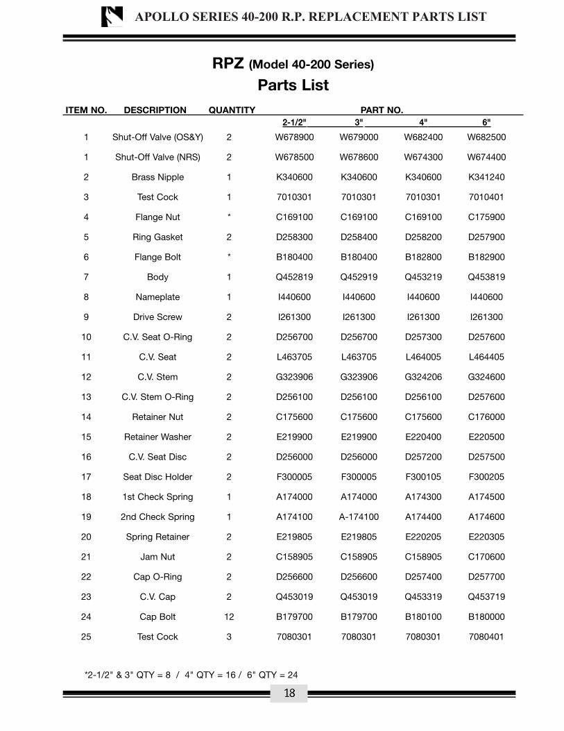
RPZ (Model 40-200 Series)
Parts List ITEM NO. DESCRIPTION QUANTITY PART NO. 2-1/2" 3" 4" 6"
1 Shut-Off Valve (OS&Y) 2 W678900 W679000 W682400 W682500
1 Shut-Off Valve (NRS) 2 W678500 W678600 W674300 W674400
2 Brass Nipple 1 K340600 K340600 K340600 K341240
3 Test Cock 1 7010301 7010301 7010301 7010401
4 Flange Nut * C169100 C169100 C169100 C175900
5 Ring Gasket 2 D258300 D258400 D258200 D257900
6 Flange Bolt * B180400 B180400 B182800 B182900
7 Body 1 Q452819 Q452919 Q453219 Q453819
8 Nameplate 1 I440600 I440600 I440600 I440600
9 Drive Screw 2 I261300 I261300 I261300 I261300
10 C.V. Seat O-Ring 2 D256700 D256700 D257300 D257600
11 C.V. Seat 2 L463705 L463705 L464005 L464405
12 C.V. Stem 2 G323906 G323906 G324206 G324600
13 C.V. Stem O-Ring 2 D256100 D256100 D256100 D257600
14 Retainer Nut 2 C175600 C175600 C175600 C176000
15 Retainer Washer 2 E219900 E219900 E220400 E220500
16 C.V. Seat Disc 2 D256000 D256000 D257200 D257500
17 Seat Disc Holder 2 F300005 F300005 F300105 F300205
18 1st Check Spring 1 A174000 A174000 A174300 A174500
19 2nd Check Spring 1 A174100 A-174100 A174400 A174600
20 Spring Retainer 2 E219805 E219805 E220205 E220305
21 Jam Nut 2 C158905 C158905 C158905 C170600
22 Cap O-Ring 2 D256600 D256600 D257400 D257700
23 C.V. Cap 2 Q453019 Q453019 Q453319 Q453719
24 Cap Bolt 12 B179700 B179700 B180100 B180000
25 Test Cock 3 7080301 7080301 7080301 7080401
*2-1/2" & 3" QTY = 8 / 4" QTY = 16 / 6" QTY = 24
APOLLO SERIES 40-200 R.P. REPLACEMENT PARTS LIST
18

15
IX PARTS LISTING 2-1/2" - 10" (Ductile Iron)
2-1/2" - 3" - 4" - 6" RPZ (Model 40-200 Series)(shown without relief valve)
NOTE: For the lead free version of the 40-200 Series, referto www.apollovalves.com
APOLLO SERIES 40-200 R.P. REPLACEMENT PARTS LIST
19

18
RPZ (Model 40-200 Series)
Parts List ITEM NO. DESCRIPTION QUANTITY PART NO. 8" 10" 1 Shut-Off Valve (OS&Y) 2 W682600 W685900
1 Shut-Off Valve (NRS) 2 W682700 W685800
2 Brass Nipple 1 K341200 K341200
3 Test Cock 1 7010401 7010401
4 Flange Nut * C175900 C179300
5 Ring Gasket 3 D259000 D265300
6 Flange Bolt ** B185700 B185800
6A Stud 2 N/A B203600
7 Body 1 Q454319 Q457219
7A Body 1 Q459319 Q459519
8 Nameplate 1 I440600 I440600
9 Drive Screw 2 I261300 I261300
10 C.V. Seat O-Ring 2 D258900 D258800
11 C.V. Seat 2 L465305 L475905
12 C.V. Stem 2 G327300 G330500
13 C.V. Stem O-Ring 2 D258700 D258700
14 Retainer Nut/Bolt *** C175400 C175400
15 Retainer Washer 2 E220800 E222900
16 C.V. Seat Disc 2 D258600 D264900
17 Seat Disc Holder 2 F300805 F301905
18 1st Check Spring 1 A174700 A177800
19 2nd Check Spring 1 A174800 A177900
20 Spring Retainer 2 E220705 E222805
21 Jam Nut 2 *C176305 *C176305
22 Cap O-Ring 2 D258800 D265100
23 C.V. Cap 2 Q454519 Q457419
24 Cap Bolt **** B169000 B188100
25 Test Cock 3 7080401 7080401
Not Shown Seat Bolt (10” only) 12 N/A B184900
8" QTY = 24 / 10" QTY = 38 8" QTY = 24 / 10" QTY = 34
8" & 10" QTY = 88" & 10" QTY = 24
APOLLO SERIES 40-200 R.P. REPLACEMENT PARTS LIST
20

17
8" - 10" RPZ (Model 40-200 Series)(shown without relief valve)
NOTE: For the lead free version of the 40-200 Series, referto www.apollovalves.com
10” seat is retained by six 5/16” socket headscrews (see seat bolt next page)
APOLLO SERIES 40-200 R.P. PARTS LIST
21

RPZ (Model 40-200 Series)
Parts List ITEM NO. DESCRIPTION QUANTITY PART NO. QUANTITY PART NO. 2-1/2" - 6" 8", 10" 26 Relief Valve Cover Bolt 7 B179600 7 B170300
27 1/2 NPT Plug 1 K300800 N/A N/A
27 3/4 NPT Plug N/A N/A 1 K301000
28 Relief Valve Cover 1 Q453105 1 Q454219
29 Relief Valve Diaphragm 1 D256400 1 D259100
30 Relief Valve Seat Ring 1 L463805 1 L465105
31 Relief Valve Seat Ring O-Ring 1 D256800 1 D2593-00
32 Relief Valve Body 1 Q453505 1 Q454119
33 Small Relief Valve O-Ring 1 D257000 1 D218600
34 Large Relief Valve O-Ring 1 D257100 1 D230400
35 Relief Valve Flange Bolt 2 B180000 4 B166900
36 1/4 NPT Plug 1 K301900 1 K301900
37 Relief Valve Flange Bolt 2 B179200 2 B166900
38 Pan Head Screw 2 B175300 1 B185600
39 Relief Valve Seat Washer 1 E220000 1 E221000
40 Relief Valve Seat Disc 1 D256300 1 D259500
41 Relief Valve Stem 1 G324000 1 G327405
42 Relief Valve Stem O-Ring 1 D256200 1 D259400
43 Relief Valve Bushing O-Ring 1 D256200 1 D259200
44 Relief Valve Bushing 1 L463915 1 L465215
45 Relief Valve Spring 1 A174200 1 A174900
46 Diaphragm Plate 1 E220100 2 E220905
47 Stem Face O-Ring N/A N/A 1 D210600
48 Diaphragm Bolt N/A N/A 1 B180000
Repair Kits PART NO.
1st Check Valve Repair Kit 2-1/2", 3" 4" 6" 8" 10"12, 13, 14, 15, 16, 17, 18, 20, 21, 22 4000901 4000A01 4000C01 4000E01 4000G01
2nd Check Valve Repair Kit12, 13, 14, 15, 16, 17, 19, 20, 21, 22 4000902 4000A02 4000C02 4000E02 4000G02
Seat Repair Kit10, 11, 22 4000903 4000A03 4000C03 4000E03 4000G03
Check Rubber Repair Kit (2 of ea.part)
10, 13, 16, 22 4000904 4000A04 4000C04 4000E04 4000G04
Relief Valve Repair Kit29, 30, 31, 33, 34, 38, 39, 40, 41, 42, 43, 4000905 4000A05 4000C05 4000E05 4000G0544, 45, 46, (47, 48)*
Relief Valve Rubber Repair Kit29, 31, 33, 34, 40, 42, 43, (47)* 4000906 4000A06 4000C06 4000E06 4000G06
*8" & 10" Only
Repair Kits
APOLLO SERIES 40-200 R.P. RELIEF VALVE PARTS LIST
22

2-1/2" - 6" Relief Valves
8" & 10" Relief Valves
NOTE: For the lead free version of the 40-200 Series, referto www.apollovalves.com
APOLLO SERIES 40-200 R.P. RELIEF VALVE PARTS LIST
23

FEBCO Model 805Y (3/4" - 2")
Model 805Y/��= ( ��������� � @�,( �A�B �B ��A�B �B
� � 6,
� �� � ��� ��� ��� ��� ��� ��� ��� ���
� � ��� � �%� ��� �� �%� ��� �� �%� ��� �� �%� ��� ��
% ������ "6�� � ��� ��� ��� ��� ��� ��� ��� ���
�� ��������� � ��� �%% ��� �%% ��� ��� ��� ���
�� -����� � ��� ��� ��� ��� ��� ��� ��� ���
�� ����3 � ��� ��� �� ��� ��� �� ��� ��� �� ��� ��� ��
�� ����� � ��� ��� ��� ��� ��� ��� ��� ���
�% ��""�4�"!�� �.�"�� � ��� ��� ��� ��� ��� ��� ��� ���
�%) ��""�4�"!�� ����"�� � ��� ��� ��� ��% ��� ��� ��� ���
�� ;���� �' � ��� ��� ��� ��� ��� ��� ��� ���
Model 805Y and 805YB Assemblies / KitsRubber Parts 5.��*�C��8����5�9����9 %�� ��� %�� ��� %�� ��� %�� ���
Check Assembly�5.��*�C��8�%8���8���8���9 %�� ��� %�� ��� %�� ��� %�� ���
Model 805YBD 6�"����E�����"�F���������*��� *� ����������������E�3���������G����� �� 7�����7 "" 3��C
/��= ( ��������� � @�,( �A�B �B ��A�B �B
�� ����� � ��� ���
Model 805YSD 6�"����E�����"�F���������*��� *� ����������������E�3���������G����� �� 7�����7 "" 3��C
/��= ( ��������� � @�,( �A�B �B ��A�B �B
�� ��������� � ��� �%%� ��� �%%� ��� ���� ��� ����
805YS Assemblies / KitsRubber Parts 5.��*�C��8����5�9����9 %�� ���� %�� ���� %�� ���� %�� ����
Check Assembly�5.��*�C��8�%8���8���8���9 %�� ���� %�� ���� %�� ���� %�� ����
Model 805YRD 6�"����E�����"�F���������*��� *� ����������������E�3���������G����� �� 7�����7 "" 3��C
/��= ( ��������� � @�,( �A�B �B ��A�B �B
�� �������� � ��� ��� ��� ���
�� � ��� � �%� ��� �� �%� ��� ��
Model 805Y Commerical Parts.��* ��������� � D������" �A�B �B ��A�B �B
� � ��� =����"� ��� ��� ��� ��� ��� ��� ��� ����B�G���A�B�G��A�B �B�G���A�B�G��A�B ��A�B�G���A�B�G��A�B ��A�B�G���A�B�G��A�B
�% ��""�4�"!� �� �F� �A�B�=#; �B�=#; ��A�B�=#; �B�=#;
�� ;���� �' ����� �A�B�=#; �A�B�=#; �A�B�=#; �A�B�=#;
;���������������� **�����"",��!��"�+"����� ���* ������63����6�����+�� ��� �������"���(����� 77��!�"!��8������ �'�8�7"������ '���8����(������"� � **�����"",��!��"�+"��+���� ��"����6(
MODEL 805Y PARTS / REPAIR KITS
Model 805Y and 805YB Assemblies / Kits
FEBCO SERIES 805Y D.C. REPLACEMENT PARTS LIST
24

FEBCO Model 805Y (3/4" - 2")
.�"������ 77
���"������ 77
H�;���� �'
H�;���� �'
H�;���� �'
)�� ��
�����"�B)B�A�B�I��B�D 6�"����E�
H�;���� �'
/��������'
��� �6����'
�%
�
����
��
�%)
�
%
��
��
�
��
SERVICE PROCEDURES FOR MODELS 805Y, 805YB, 805YS1. Disassembly-Check Valves
�( " �����"�����6� ��"������� 77�!�"!��(��"��6�����6��"����������+,� ������ H�8�H����6�H������� �'�(
+( J�����3�������������� ���������F��3�����(�NOTE: Cap is spring loaded.�( ��* !��������� �����6�����'�����*+",(
6( .7���,���"���*� ����*�"���*������"�����+��"� ��� ����������6�����7����� 7�������6�� "������������8��������+����* !�6�3��������7�"���� 7�������6��6����*��(
5�9��A�B���� ����B�6�!����C��(�����5�A�9����*��
5�9���A�B���6��B�6�!����C�(�����5�A�9����*��
2. Check Valve Seal Replacement�( � "6�����'�����*+",���� ������6���6���* !������38�3�����8���6������6���(�)J;.�=C�;������� 7��"����� �� ������ "��*�,�6�*��
������������6���K���������������,����"���*���(�� �� ���������� ��*��'����"��� ����6������7����(
+( .����""���3�6�����7�����"������6����� "6�� (
�( # ���� ��6����3��������6��������3�������� 3(
3. Assembly�( J�����!������� ��6����7 ������*+",�3��������7 "" 3���������"���������� �(
+( ; ���������������""��� �8����",��������� ����� 7�� � ���"�+������� ����,�/�)����� !�6�������� ������ � ������ ��� �����*+",(
�( ;���������� ���������� ���� ��� ��� �(
TESTING)""�*��������"�6�!������� �"6�+����������6� �������"���+������ ����������� ,�����3 �'���� �����",(�;�������*+",��� �"6�+������ �6�����*�� 7�������"������""��� �8��7������� !����� ��*����������8���6�����"�������� ��"",�������7���(�)������+"��������� ��6�������� ���+"����6�+,����/ ��6��� ��7 ��� ��� ������ �� ��� "���6��,6���"�������������������J��! �����,� 7�� ����� ���"�7 �����5J�98� ;���)*�� ����-�����- �'��)�� ����� ��5)--)98�;���)*�� ������ ����,� 7�������� ,�$������ ���5)��$���� ��������9���6��������6��������6��6�)�� ����� ��5)=A�)����L��9(�#"������ ���"���������"�� �,����� ���,����, ��������7 ��* ��������7�����7 �*��� �(
HOW TO ORDER REPAIR KITS�( > ��������*���*+�����6�'�����*+�����������*�����������*����"(
�( 4���7,�������F�� 7�����!�"!����������������� �+�����6�7 �(
�( #� !�6��7�""�* 6�"���*+���" ����6� ��.(�(��"���(
�( ��� �6�'�����*+��(
�( )������"���*+���5" ����6� ������.(�(��"���9�3�""����������� �6����������� ����'��� (
�( ������, ���" ��"�/$���#�����������+�� �(
FEBCO SERIES 805Y D.C. REPLACEMENT PARTS LIST
25

MAINTENANCE MANUAL MODELS 805YD, 806YD 21/2"- 10" (65 – 250mm)
Repair PartsModel 805YD, 806YD Repair Parts
ITEM DESCRIPTION MATERIAL 21⁄2" 3" 4" 6" 8" 10"7.1 Screw Brass - - 3⁄8-16 x 11⁄2 3⁄8 - 16 x 2 3⁄8 - 16 x 2 3⁄8 - 16 x 2
12.1 O-ring Buna-N568-238
31⁄2 x33⁄4 x 1⁄8568-246
41⁄2 x 43⁄4 x 1⁄8568-254
51⁄2 x 53⁄4 x 1⁄8568-264
71⁄2 x 73⁄4 x 1⁄8568-273
91⁄2 x 10 x 1⁄8105⁄16 x 109⁄16 x 1⁄8
13 Cap Screw SS 7⁄16 -14 x 1 7⁄16 -14 x 1 1⁄2 -13 x 11⁄4 5⁄8 -11 x 11⁄2 3⁄4 -10 x 11⁄2 3⁄4 -10 x 13⁄4
14 O-ring Buna-N568-244
41⁄4 x 41⁄2 x 1⁄8568-252
51⁄4 x 51⁄2 x 1⁄8568-263
71⁄4 x 71⁄2 x 1⁄8568-272
91⁄2 x 93⁄4 x 1⁄8568-451
11 x 111⁄2 x 1⁄4123⁄4 x 13 x 1⁄8
15 Lock-Nut Brass3⁄8 -24Elastic
3⁄8 -24Elastic
3⁄4 -16Elastic
3⁄4 -16Elastic
7⁄8 -14Elastic
7⁄8 -14Elastic
17 Bolt & Nut Steel 5⁄8 -11 x 21⁄4 5⁄8 -11 x 21⁄2 5⁄8 -11 x 23⁄4 3⁄4 -10 x 3 3⁄4 -10 x 31⁄4 7⁄8 - 9 x 31⁄240 Ball Valve Brass 1⁄2 IPS 200# 1⁄2 IPS 200# 1⁄2 IPS 200# 3⁄4 IPS 200# 3⁄4 IPS 200# 3⁄4 IPS 200#
51 O-ring Buna-N568-014
1⁄2 x 5⁄8 x 1⁄16
568-0141⁄2 x 5⁄8 x 1⁄16
568-1163⁄4 x 15⁄16 x 1⁄16
568-1163⁄4 x 15⁄16 x 1⁄16
568-1187⁄8 x 11⁄16 x 3⁄32
568-1187⁄8 x 11⁄16 x 3⁄32
41** Nipple Bronze - - 1⁄2 x Close 3⁄4 x Close 3⁄4 x Close 3⁄4 x Close304** 90o Elbow Bronze - - 1⁄2 1⁄2 1⁄2 3⁄4305** Nipple Bronze - - 1⁄2 x 5 3⁄4 x 6 3⁄4 x 6 3⁄4 x 6316** Bushing Bronze - - 1⁄2 x 3⁄4 - - -301** Nipple Bronze - - - 3⁄4 x 21⁄2 3⁄4 x 21⁄2 3⁄4 x 21⁄2
** Used in the Model 806YD only.These parts are commercially available through most hardware distributors or retailers. Shutoff valves, testcocks, flange gaskets, etc., are also commercially available but not listed. The water meter is a 5⁄8 x 3⁄4 size. Several brands are USC approved for use on the Model 806YD. Contact the factory for additional information.
FEBCO SERIES 805YD & 806YD D.C. REPLACEMENT PARTS
26
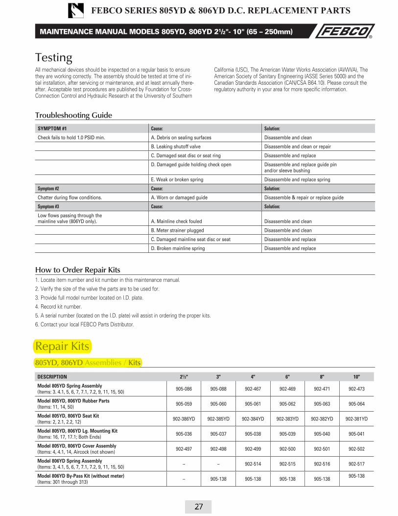
MAINTENANCE MANUAL MODELS 805YD, 806YD 21/2"- 10" (65 – 250mm)
How to Order Repair Kits1. Locate item number and kit number in this maintenance manual.
2. Verify the size of the valve the parts are to be used for.
3. Provide full model number located on I.D. plate.
4. Record kit number.
5. A serial number (located on the I.D. plate) will assist in ordering the proper kits.
6. Contact your local FEBCO Parts Distributor.
Repair Kits805YD, 806YD Assemblies / Kits
SYMPTOM #1 Cause: Solution:
Check fails to hold 1.0 PSID min. A. Debris on sealing surfaces Disassemble and clean
B. Leaking shutoff valve Disassemble and clean or repair
C. Damaged seat disc or seat ring Disassemble and replace
D. Damaged guide holding check open Disassemble and replace guide pinand/or sleeve bushing
E. Weak or broken spring Disassemble and replace spring
Symptom #2 Cause: Solution:
Chatter during flow conditions. A. Worn or damaged guide Disassemble & repair or replace guide
Symptom #3 Cause: Solution:
Low flows passing through the mainline valve (806YD only). A. Mainline check fouled Disassemble and clean
B. Meter strainer plugged Disassemble and clean
C. Damaged mainline seat disc or seat Disassemble and replace
D. Broken mainline spring Disassemble and replace
Troubleshooting Guide
TestingAll mechanical devices should be inspected on a regular basis to ensure they are working correctly. The assembly should be tested at time of ini-tial installation, after servicing or maintenance, and at least annually there-after. Acceptable test procedures are published by Foundation for Cross- Connection Control and Hydraulic Research at the University of Southern
California (USC), The American Water Works Association (AWWA), The American Society of Sanitary Engineering (ASSE Series 5000) and the Canadian Standards Association (CAN/CSA B64.10). Please consult the regulatory authority in your area for more specific information.
DESCRIPTION 21⁄2" 3" 4" 6" 8" 10"
Model 805YD Spring Assembly(Items: 3. 4.1, 5, 6, 7, 7.1, 7.2, 9, 11, 15, 50)
905-086 905-088 902-467 902-469 902-471 902-473
Model 805YD, 806YD Rubber Parts (Items: 11, 14, 50)
905-059 905-060 905-061 905-062 905-063 905-064
Model 805YD, 806YD Seat Kit(Items: 2, 2.1, 2.2, 12)
902-386YD 902-385YD 902-384YD 902-383YD 902-382YD 902-381YD
Model 805YD, 806YD Lg. Mounting Kit (Items: 16, 17, 17.1; Both Ends)
905-036 905-037 905-038 905-039 905-040 905-041
Model 805YD, 806YD Cover Assembly(Items: 4, 4.1, 14, Aircock (not shown)
902-497 902-498 902-499 902-500 902-501 902-502
Model 806YD Spring Assembly(Items: 3, 4.1, 5, 6, 7, 7.1, 7.2, 9, 11, 15, 50)
– – 902-514 902-515 902-516 902-517
Model 806YD By-Pass Kit (without meter)(Items: 301 through 313)
– 905-138 905-138 905-138 905-138905-138
Repair Kits805YD, 806YD KitsAssemblies /
FEBCO SERIES 805YD & 806YD D.C. REPLACEMENT PARTS
27
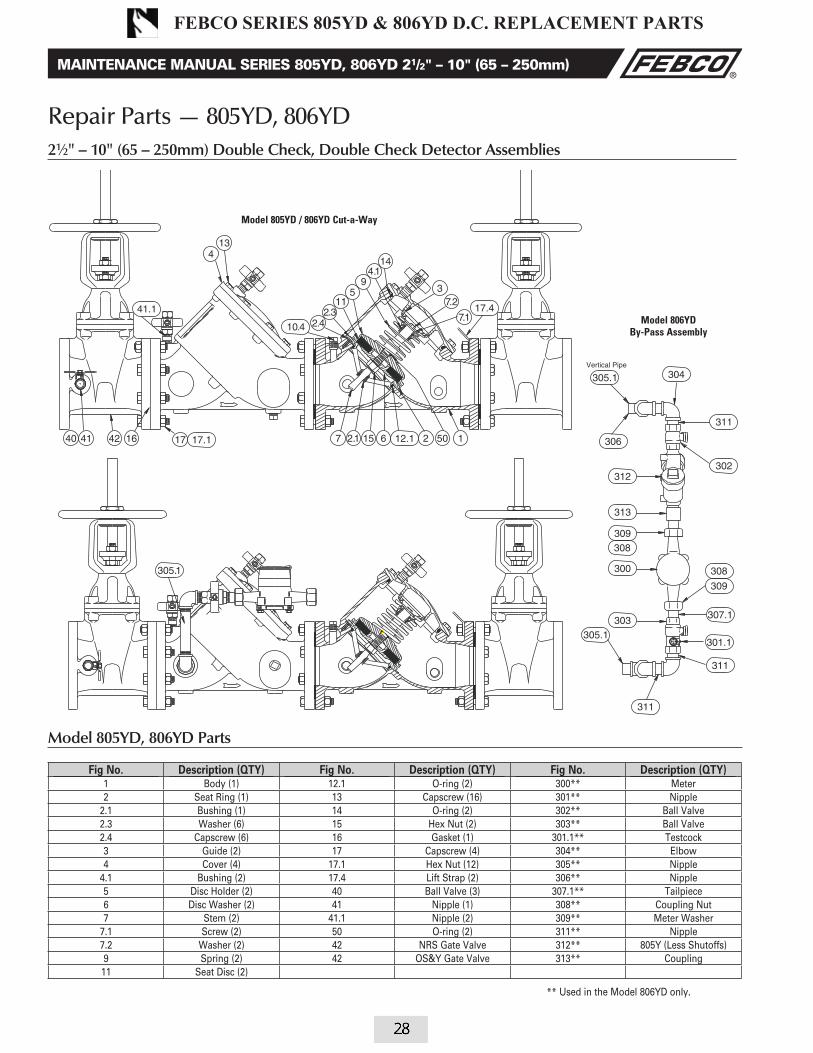
MAINTENANCE MANUAL SERIES 805YD, 806YD 21/2" – 10" (65 – 250mm)
Model 805YD, 806YD Parts
Fig No. Description (QTY) Fig No. Description (QTY) Fig No. Description (QTY)1 Body (1) 12.1 O-ring (2) 300** Meter2 Seat Ring (1) 13 Capscrew (16) 301** Nipple
2.1 Bushing (1) 14 O-ring (2) 302** Ball Valve2.3 Washer (6) 15 Hex Nut (2) 303** Ball Valve2.4 Capscrew (6) 16 Gasket (1) 301.1** Testcock3 Guide (2) 17 Capscrew (4) 304** Elbow4 Cover (4) 17.1 Hex Nut (12) 305** Nipple
4.1 Bushing (2) 17.4 Lift Strap (2) 306** Nipple5 Disc Holder (2) 40 Ball Valve (3) 307.1** Tailpiece6 Disc Washer (2) 41 Nipple (1) 308** Coupling Nut7 Stem (2) 41.1 Nipple (2) 309** Meter Washer
7.1 Screw (2) 50 O-ring (2) 311** Nipple7.2 Washer (2) 42 NRS Gate Valve 312** 805Y (Less Shutoffs)9 Spring (2) 42 OS&Y Gate Valve 313** Coupling11 Seat Disc (2)
Model 806YD By-Pass Assembly
Model 805YD / 806YD Cut-a-Way
4.
1
** Used in the Model 806YD only.
Repair Parts — 805YD, 806YD21⁄2" – 10" (65 – 250mm) Double Check, Double Check Detector Assemblies
28
FEBCO SERIES 805YD & 806YD D.C. REPLACEMENT PARTS

PARTS LIST
Item Description Qty. 1/2 3/4 1 11/4 11/2 2� � 6, � ������ ������ ������ ������ ������ ������
�(� ;��"����� � ������ ������ �����% ������ ������ ������
�(� � ��� � �%������ �%������ �%������ �%������ �%������ �%������
� !�� � ������ ������ ������ ������ ������ ������
�(� � ��� � �%������ �%������ �%���%�� �%������ �%������ �%������
� ���� � ����%� ����%� ������ ������ ������ ������
�(� � ��� � �%������ �%������ �%������ �%������ �%������ �%������
� # ���� � ����%� ����%� ������ ������ ������ ������
� ������ ��� � ������ ������ ������ ������ ������ ������
�(� ������������� � ����%� ����%� ����%� ������ ������ ������
�(� � ��6��������3 � �������� �������� �������� ��%����� ��%����� ��%�����
� ����� � ������ ������ ������ �����% �����% �����%
� &��6� � ����%� ����%� ������ ������ ������ ������
� ��������������� � ����%� ����%� ������ ������ ������ ������
%M ��""�4�"!��;����6 � ������ ������ ������ ������ ������ ������
J�� ��$�6��4�;����6 � ������ ������ �����% ����%� ����%� ����%�
%(�M ��""�4�"!� � ������ ������ �����% ������ ������ ������
J�� ��$�6���""�4�"!� � ����%� ����%� ����%� ����%� ����%� ����%�
�� ;���� �' � ������ ������ ������ ������ ������ ������
�� ��������� ��4 � ������ ������ ������ ������ ������ ������
�� ��G����������3 �� �������� �������� �������� �������� �������� ��������
MJ�� ��$�6���""�4�"!��= ���� 3�(
FEBCO Model 850 / 850U (1/2" - 2") #����
FEBCO SERIES 850 & 850U D.C. REPLACEMENT PARTS
29

FEBCO Model 850 / 850U (1/2" - 2")
REPAIR KITS
How to order parts and Repair Kits
�( > ��������*���*+�����6�'�����*+�����������*�����������*����"(
�( 4���7,�������F�� 7�����!�"!����������������� �+�����6� �(
�( #� !�6��7�""�* 6�"���*+���" ����6� ��.(�(��"���(
�( &�!��'�����*+��(
�( )������"���*+���5" ����6� ������.(�(��"���9�3�""����������� �6����������� ����'���(
�( ������, ���" ��"�/$���#�����������+�� �(
850 Check Module Assembly 1/2 3/4 1 11/4 11/2 2
#����= ( %�� ��� %�� ��� %�� ��% %�� ��� %�� ��� %�� ���
All Sizes Include:
Item Describtion Qty. Item Describtion Qty.
� ���� � �(� ������������� �
�(� � ��� � �(� � ��6��������3 �
� # ���� � � ����� �
� ��������� � � &��6� �
850 Single Poppet Kit 1/2 3/4 1 11/4 11/2 2
#����= ( %�� ��% %�� ��% %�� ��� %�� ��� %�� ��� %�� ���
All Sizes Include:
Item Describtion Qty. Item Describtion Qty.
� # ���� � �(� ������������� �
� ��������� � �(� � ��6��������3 �
850 Rubber Parts Kit 1/2 3/4 1 11/4 11/2 2
#����= ( %�� ��� %�� ��� %�� ��� %�� ��� %�� ��� %�� ���
All Sizes Include:
Item Describtion Qty. Item Describtion Qty.
�(� � ��� � � ��������� �
�(� � ��� �
850 Rubber Parts Kit
850 Check Module Assembly
850 Single Poppet Kit
REPAIR KITS
FEBCO SERIES 850 & 850U D.C. REPLACEMENT PARTS
30

EXPLODED VIEW
CHECKMODULE
FEBCO Model 850 / 850U (1/2" - 2")
FEBCO SERIES 850 & 850U D.C. REPLACEMENT PARTS
31

MAINTENANCE MANUAL SERIES 850, 856, 870V & 876V 21⁄2"- 10" (65 – 250mm)
Repair Parts 850 / 85621⁄2" – 10" (65 – 250mm) Double Check / Double Check Detector Assemblies
ITEM DESCRIPTION STYLE SIZE 21⁄2" & 3" (65 – 80mm) 4" (100mm) 6" (150mm) 8" & 10" (200 – 250) DISC ASSEMBLY N-Shape Part # 905182 905153 905154 905155 Items 6, 16, 17 Only SINGLE SPRING MODULE 850 Part # 905142 905143 905144 905145 Items 5.1, 7, 8, 9, 9.1, 10, 11, 12, 12.1 856 Part # 905147 905148 905149 905150 CHECK REPLACEMENT KIT 850 Part # 905527 905534 905537 905539 Items 2.1, and 3 - 17 856 Part # 905529 905536 905538 905541 SEAT RING / ARM ASSEMBLY ALL Part # 905157 905158 905159 905160 Items 3, 3.1, 3.2, 3.4, 4, 4.1, 4.2, 5 RUBBER PARTS KIT ALL Part # 905249 905163 905164 905165 Items 2.1, 3.1, 6, 15, 26, 35, 35.1, 45, 45.1 COVER ASSEMBLY With Bulkhead Part # 905167 905168 905169 905170 Items 2, 2.1, 15 Fitting TAPPED Part # 905376 905377 905378 905379 BULKHEAD FITTING FOR COVER* 850 Part # 905275 905277 Items 43.1, 45.1, 46.1, 47.1 856 Part # 905275 905277 BULKHEAD FITTING FOR BODY* 850 Part # 905276 905277 Items 43, 45, 46, 47 856 Part # 905277
* Bulkhead fittings are not furnished on late models. Very early productions of Series 856 may require a different bulkhead fitting. Consult your FEBCO representative for assistance.
Second CheckFirst Check
Test Cock
#3
Test Cock
#4
Test Cock
#1
Test Cock
#2
Test Cock
#2
Test Cock
#1
#1 Inlet Shutoff Valve #2 Outlet Shutoff Valve
RUBBER PARTS KIT
FEBCO SERIES 850 & 856 D.C. REPLACEMENT PARTS
32

ITEM DESCRIPTION STYLE SIZE 21⁄2" & 3" (65 – 80mm) 4" (100mm) 6" (150mm) 8" (200mm) 10" (250mm) DISC ASSEMBLY ALL Part # 905152 905153 905154 905155 400145 Items 6, 16, 17 (10", Item 6 only) SINGLE SPRING MODULE 870, Part # 905142 905143 905144 905145 905146 Items 5.1, 7, 8, 9, 9.1, 870V 10, 11, 12, 12.1 876 Part # 905147 905148 905149 905150 905151 876V CHECK REPLACEMENT KIT 870, Part # 905528 905534 905537 905539 905540 Items 2.1, and 3 - 17 870V 876, Part # 905530 905536 905538 905541 905542 876V SEAT RING / ARM ASSEMBLY ALL Part # 905157 905158 905159 905160 905161 Items 3, 3.1, 3.2, 3.4, 4, 4.1, 4.2, 5 RUBBER PARTS KIT ALL Part # 905162 905163 905164 905165 905166 Items 2.1, 3.1, 6, 15, 26, 35, 35.1, 45, 45.1 COVER ASSEMBLY (Inlet Check)* ALL Part # 905167 905168 905169 905170 905171 Items 2, 2.1, 15 COVER ASSEMBLY (Outlet Check)* ALL Part # 905244 905245 905246 905247 905248 Items 2, 2.1, 15 BULKHEAD FITTING FOR COVER* 870, Part # 905275 905277 Items 43.1, 45.1, 46.1, 47.1 870V 876, Part # 905275 905277 876V BULKHEAD FITTING FOR BODY* 870, Part # 905276 905277 Items 43, 45, 46, 47 870V 876, Part # 905277 876V
* Bulkhead fittings are not furnished on late models. Very early productions may require a different bulkhead fitting. Consult your FEBCO representative for assistance.
MAINTENANCE MANUAL SERIES 850, 856, 870V & 876V 21⁄2"- 10" (65 – 250mm)
Repair Parts 870, 870V / 876, 876V21⁄2" – 10" (65 – 250mm) Double Check / Double Check Detector Assemblies
First Check
Test Cock #3
Test Cock
#1
Test Cock
#2
Second Check
#2 Outlet Shutoff Valve#1 Inlet Shutoff Valve
Test Cock #4
RUBBER PARTS KIT
FEBCO SERIES 870 & 876 D.C. REPLACEMENT PARTS
33

14
MAINTENANCE MANUAL MODELS 825Y, 825YA, 825, 825D, 825YD & 826YD
ITEMNO.
DESCRIPTION QTY.*SIZE¾"
SIZE1"
SIZE1¼"
SIZE1½"
SIZE2"
29 Bal l Valve (Inlet) 1 781-053 781-054 781-055 781-056 781-057
29A Bal l Valve (Outlet) 1 781-048 781-049 781-050 781-051 781-052
30 T estcock 4 781-074 781-074 781-075 781-075 781-075
Shutoffs: Model 825Y & YA
ITEMNO.
DESCRIPTION QTY.*SIZE¾"
SIZE1"
SIZE1¼"
SIZE1½"
SIZE2"
3 Bushing 3 500-290 500-290 500-290 500-290 500-290
4 O-ring 2 398-202-72 398-202-72 398-202-72 398-202-72 398-202-7 2
5 Gasket 2 340-078 340-078 340-078 340-079 340-079
6 Capscrew 2 515-513-05 515-513-05 515-513-05 515-514-06 515-514-0 6
7 Cap 2 101-134 101-134 101-134 101-135 101-135
8 O-ring 2 398-226-72 398-226-72 398-226-72 398-235-72 398-235-7 2
9 Disc Holder 2 500-270 500-270 500-270 500-278 500-278
10 Seat Disc 2 400-099 400-099 400-099 400-103 400-103
11 Washe r 2 300-084 300-084 300-084 300-108 300-108
12 Screw 2 516-543-03 516-543-03 516-543-03 516-543-03 516-543-0 3
13 Spring (Inlet) 1 630-125 630-125 630-125 630-137 630-137
14 Spring (Outlet) 1 630-1 15 630-1 15 630-1 15 630-1 18 630-1 18
15 Bolt 4 511-514-06 51 1-514-06 51 1-514-06 ----- -----
15 Bolt 8 ----- ----- ----- 51 1-515-07 511-515-07
16 Cover 1 101-029 101-029 101-046 101-035 101-035
17 Diaphragm 1 400-101 400-101 400-101 400-104 400-104
18 Screw 1 700-107 700-107 700-107 519-513-03 519-513-0 3
19 Butto n 1 500-284 500-284 500-284 300-107 300-107
20 Spring 1 630-126 630-126 630-126 630-138 630-138
21 Mainstem 1 500-273 500-273 500-273 500-280 500-280
22 O-ring 1 398-1 13-72 398-1 13-72 398-1 13-72 398-120-72 398-120-7 2
23 Guide 1 500-277 500-277 500-277 500-281 500-281
24 O-ring 1 398-022-72 398-022-72 398-022-72 398-127-72 398-127-7 2
25 Seat Disc 1 400-102 400-102 400-102 400-105 400-105
26 Washe r 1 300-104 300-104 300-104 300-105 300-105
27 Screw 1 700-137 700-137 700-137 519-513-03 519-513-0 3
101 Seat Ring (Reli ef V alve) 1 200-779 200-779 ----- 200-780 200-780
102 O-ring (Reli ef V alve) 1 398-019-72 398-019-72 ----- 398-026-72 398-026-7 2
103 Elbow (Y A only) 2 101-194 101-195 ----- 101-189 101-190
104 O-ring (Y A only) 2 398-223-72 398-223-72 ----- 398-230-72 398-230-7 2
Model 825Y & YA Part Numbers (Sizes ¾–2”)
Model 825Y and YA (3/4–2") Parts
* Quantity required per valve.
* Quantity required per valve.
FEBCO SERIES 825Y R.P. REPLACEMENT PARTS
34 34

15
MAINTENANCE MANUAL MODELS 825Y, 825YA, 825, 825D, 825YD & 826YD
DESCRIPTION QT Y. * SIZE
3/4"SIZE
1"SIZE11/4"
SIZE11/2"
SIZE2"
Check V alve Rubber Ki t (2 ea. 8, 10) 1 Kit 905-042 905-042 905-042 905-053 905-053 Relief V alve Rubber ( 1 ea. 17, 22, 24, 25) 1 Kit 905-043 905-043 905-043 905-054 905-054
825YR Seat Ring Repair Kit (35, 36) 1 Kit 905-280 905-280 ----- 905-281 905-281
Check V alve As sem bly (1 ea. 8, 9, 10, 1 1, 12) 2 As sy . 905-044 905-044 905-044 905-055 905-055
Relief Valve A ssembly (1 ea. 17, 18, 19, 20, 21, 22, 23, 24, 25, 26, 27)
1 As sy . 905-045 905-045 905-045 905-056 905-056
RV Seat Ring Kit (101, 102) 1 Kit 905-1 13 905-113 ----- 905-1 14 905-1 14Complete Rubber Parts Kit (3, 4, 5, 8, 10, 17, 22, 24, 25, 102)
1 Ki t 905-111 905-111 905-111 905-112 905-112
Assemblies / Kits: Model 825Y & YA
Model 825YA (3/4–2")
Figure No. 12
Model 825Y, 825YR and YA (3/4–2") Parts (Cont.)
103
104 (O-ring)
103
* Quantity required per valve.
Model 825Y (3/4–2")
Figure No. 11
* Denotes Commercial Parts Available (see pages 31-33).Unit is shown with ball valve shutoffs. Some parts are sold in kits only. Consult Parts Price List for specifics.
16
15*
20
102101
30*4
24*
17
22
19
2526
23
21
18*
29
Washer
3
Relief Valve Body
30*
6
4
Discharge Shield
10
12
7
8*
13
9
8*
1
Check Assembly
29A
14
7
11
6
27
Relief Valve Assembly
Complete Rubber Parts Kit
Check Valve Rubber Ki t (2VV Ki t (ubbRelief V alve Rubber
Assemblies / Kits:
FEBCO SERIES 825Y R.P. REPLACEMENT PARTS
3535

MAINTENANCE MANUAL SERIES 860 & 860U 1/2"- 2" (15 – 50mm)
Exploded View
View as shown is for sizes 11/2" - 2" (40 – 50mm)
Relief Valve Module Kit(not including 21)
* Quantity varies with valve size; 6 each for 1/2" and 3/4, 8 each for 1", 14 each 11/4", 11/2", 2"
Check ModuleAssembly Kit
ITEM DESCRIPTION QUANTITY1 Body 11.2 Tailpiece 11.4 O-Ring 12 Cover 12.2 O-Ring 13 Seat 23.1 O-Ring 23.2 Inlet Ring
1
(11/4" & 11/2"4 Poppet 25 Seat Disc 25.1 Disc Retainer 25.2 Round HD Screw 26 Spring
1
(1st Check Spring)6.1 Spring
1
(2nd Check Spring) 7 Guide 28 Retainer Spacer 19* Ball Valve Tapped 1 Union End BV Tapped 19.1* Ball Valve 1 Union End Ball Valve 111 Test Cock 412 Seat Ring - RV 112.1 Gasket Ring - RV 113 Spring - RV 114 Seat Disc - RV 115 Diaphragm - RV 116 Outer Diaphragm - RV 117 Small Piston - RV 117.1 Round HD Screw - RV 117.2 Washer - RV 117.3 Hex Nut - RV 118 Cylinder - RV 118.1 Slip Ring Cylinder - RV 118.2 Slide (Plug) - RV 119 Cover - RV 120 O-Ring - RV 121 Hex HD Capscrew *22 Large Piston - RV 123 Guide - RV 1
FEBCO SERIES 860 & 860U R.P. REPLACEMENT PARTS
36

MAINTENANCE MANUAL SERIES 860 & 860U 1/2"- 2" (15 – 50mm)
Repair KitsHow to order parts and Repair Kits1. Locate item number and kit number in this maintenance manual.
2. Verify the size of the valve the parts are to be used on.
3. Provide full model number located on I.D. plate.
4. Give kit number.
5. A serial number (located on the I.D. plate) will assist in ordering the proper kits.
6. Contact your local FEBCO Parts Distributor.
Check Module Rubber Kit 1/2" (15mm) 3/4" (20mm) 1" (25mm) 11/4" (32mm) 11/2" (40mm) 2" (50mm)
Part No. 905342 905342 905343 905344 905344 905344
ALL SIZES INCLUDE:ITEM DESCRIPTION QTY. ITEM DESCRIPTION QTY.
1.4 O-Ring 1 3.1 O-Ring 2
2.2 O-Ring 1 5 Seat Disc 2
Relief Valve Rubber Kit 1/2" (15mm) 3/4" (20mm) 1" (25mm) 11/4" (32mm) 11/2" (40mm) 2" (50mm)
Part No. 905345 905345 905345 905346 905346 905346
ALL SIZES INCLUDE:ITEM DESCRIPTION QTY. ITEM DESCRIPTION QTY.
12 Seat Ring - RV 1 16 Outer Diaphragm - RV 1
12.1 Gasket Ring - RV 1 18.1 Slip Ring Cylinder - RV 2
14 Seat Disc - RV 1 20 O-Ring - RV 1
15 Diaphragm - RV 1
Check Module Rubber Kit
Relief Valve Rubber Kit
Repair Kits
FEBCO SERIES 860 & 860U R.P. REPLACEMENT PARTS
37

MAINTENANCE MANUAL SERIES 860 & 860U 1/2"- 2" (15 – 50mm)
Repair Kits (Continued)
Relief Valve Module Assembly Kit 1/2" (15mm) 3/4" (20mm) 1" (25mm) 11/4" (32mm) 11/2" (40mm) 2" (50mm)
Part No. 905353 905353 905353 905354 905354 905354
ALL SIZES INCLUDE:ITEM DESCRIPTION QTY. ITEM DESCRIPTION QTY.
12 Seat Ring - RV 1 17.3 Hex Nut - RV 1
12.1 Gasket Ring - RV 1 18 Cylinder 1
13 Spring - RV 1 18.1 Slip Ring Cylinder - RV 2
14 Seat Disc - RV 1 18.2 Slide Plug 1
15 Diaphragm - RV 1 19 Cover 1
16 Outer Diaphragm - RV 1 20 O-Ring - RV 1
17 Small Piston - RV 1 22 Large Piston - RV 1
17.1 Round HD Screw - RV 1 23 Guide - RV 1
17.2 Washer - RV 1
2nd Check Module Assembly 1/2" (15mm) 3/4" (20mm) 1" (25mm) 11/4" (32mm) 11/2" (40mm) 2" (50mm)
Part No. 905347 905347 905349 905351 905351 905351
ALL SIZES INCLUDE:ITEM DESCRIPTION QTY. ITEM DESCRIPTION QTY.
3 Seat 1 5.1 Disc Retainer 1
3.1 O-Ring 1 5.2 Round HD Screw 1
4 Poppet 1 6 Spring 1
5 Seat Disc 1 7 Guide 1
1st Check Module Assembly 1/2" (15mm) 3/4" (20mm) 1" (25mm) 11/4" (32mm) 11/2" (40mm) 2" (50mm)
Part No. 905348 905348 905350 905352 905352 905352
ALL SIZES INCLUDE:ITEM DESCRIPTION QTY. ITEM DESCRIPTION QTY.
3 Seat 1 5.1 Disc Retainer 1
3.1 O-Ring 1 5.2 Round HD Screw 1
4 Poppet 1 6.1 Spring 1
5 Seat Disc 1 7 Guide 1
1st Check Module Assembly
2nd Check Module Assembly
Relief Valve Module Assembly Kit
Repair Kits
FEBCO SERIES 860 & 860U R.P. REPLACEMENT PARTS
38

1 Body (860) 1 880-131 880-132 880-133 880-134 880-135 N/A
Body (880V) 1 880-193 880-194 880-188 880-189 880-190 880-191
1.1 Pipe Plug (860) 1 578-171-50 578-171-50 578-171-50 578-171-50 578-171-50 N/A
1.2 Bushing 1 571-161-54 571-161-54 571-161-54 571-161-54 571-161-54
2 Cover (860) 2 880-250 880-250 880-251 880-252 880-253 N/A
Cover 1st Check (880V) 1 880-192 880-192 880-175 880-176 880-177 880-178
2.1 O-Ring 2 39625579 39625579 396-261-79 396-269-79 396-276-79 396-279-79
2.2 Capscrew 16 51101614 51101614 511-017-14 511-019-18 511-020-18 511-020-20
2.3 Hex Nut 16 52101600 52101600 521-017-00 521-101-90 521-020-00 521-020-00
2.4 Expansion Pin 2 360-089 360-089 360-089 360-089 360-089 360-089
2.5 Cover 2nd Check (880V) 1 880-106 880-106 880-107 880-108 880-109 880-110
3 Seat Ring 2 110-071 110-071 110-072 101-259 110-074 101-261
3.1 Gasket 2 450-102 450-102 450-106 450-108 450-109 450-110
3.2 Socket Head Screw 8 517-514-10 517-514-10 517-514-10 517-514-10 517-514-10 517-514-12
3.4 Elastic Stop Nut 8 523-514-00 523-514-00 523-514-00 523-514-00 523-514-00 523-514-00
4 Arm 2 101-212 101-212 101-207 101-208 101-210 101-211
4.1 Bushing Swing Pin 4 500-338 500-338 500-338 500-388 500-338 500-337
4.2 Swing Pin 2 240-137 240-137 240-137 240-138 240-139 240-140
5 Retaining Clip 4 740-118 740-118 740-118 740-118 740-118 740-119
5.1 Hairpin Cotter 4 740-120 740-120 740-120 740-120 740-120 740-120
6 Check Disk (860) 2 402-014 402-014 402-006 402-007 402-008 N/A
Check Disk (880V) 2 402-030 402-030 402-031 402-032 402-008 N/A
Seat Disk (10"-880V) 2 N/A N/A N/A N/A N/A 400-145
6.1 Disk Holder (10"-880V) 2 N/A N/A N/A N/A N/A 190-029
6.2 Disk Retainer (10"-880V) 2 N/A N/A N/A N/A N/A 190-034
6.3 Capscrew (10"-880V) 6 N/A N/A N/A N/A N/A 511-515-05
7 Load Pin 2 240-130 240-130 240-130 240-131 240-131 240-132
8 Lwr Spring Retainer 2 101-203 101-203 101-203 101-204 101-204 101-205
9 Spring Stem 2 240-116 240-116 240-117 240-118 240-119 240-120
9.1 Elastic Stop Jam Nut 2 720-054 720-054 720-054 720-055 720-055 720-055
10 Spring 1st Check 2 630-154 630-154 630-155 630-156 630-157 630-158
10.1 Spring 2nd Check 2 630-162 630-162 630-163 630-151 630-164 630-165
10.2 Spring Shim 2nd Check (8") 1 N/A N/A N/A N/A 500-354 N/A
11 Spring Guide 2 360-086 360-086 360-086 360-087 360-087 101-217
12 Upr Spring Retnr 2 101-216 101-216 101-216 101-206 101-206 101-221
12.1 Bushing-Spr. Stem 2 500-344 500-344 500-344 500-345 500-345 500-340
13 Pivot Bearing 2 101-218 101-218 101-218 101-219 101-219 101-220
14 Flange Gasket 2 780-365 780-366 780-367 780-368 780-369 780-370
15 Bearing Socket 2 500-335 500-335 500-335 500-336 500-336 500-336
16 Hex Jam Nut 2 524-515-00 524-515-00 524-515-00 524-517-00 524-517-00 511-517-06
17 Washer 2 360096 360-096 360-096 360-097 360-097 360-097
18 Flange Bolt ( ) (8)511-019-22 (8)511-019-22 (12)511-019-22 (12)511-019-22 (12)511-019-22 (24)511-019-22
18.1 Flange Nut ( ) (8)511-019-22 (8)511-019-22 (20)511-019-22 (20)511-019-22 (20)511-019-22 (24)511-019-22
18.2 Flange Stud 4 N/A N/A 513-019-26 513-019-26 513-019-26 N/A
20 R.V. Cover 1 110-012 110-012 110-012 110-012 110-012 110-012
20.1 Bleed Screw 2 519-513-03 519-513-03 519-513-03 519-513-03 519-513-03 519-513-03
Model 860/880V (21/2" - 10") Parts List
Item Description Quantity 21/2" 3" 4" 6" 8" 10"
Note: Many of the above items are only available as part of a repair kit.12
MAINTENANCE MANUAL MODELS 860 & 880V 21/2" – 10"
IOM-F-860_880V.indd 12 7/11/08 10:45:28 AM
FEBCO SERIES 860 & 880V R.P. REPLACEMENT PARTS
39

20.2 Gasket 2 340-078 340-078 340-078 340-078 340-078 340-078
21 R.V. Body 1 110-011 110-011 110-011 110-011 110-011 110-011
22 Cover Bolt 8 511-515-08 511-515-08 511-515-08 511-515-08 511-515-08 511-515-08
23 Elbow 1 880-154 880-154 880-154 880-154 880-154 880-154
24 RV Mtg Bolt 4 511-014-10 511-014-10 511-014-10 511-014-10 511-014-10 511-014-10
24.1 Washer - RV 4 360-090 360-090 360-090 360-090 360-090 360-090
24.2 Cap Screw 4 511-014-18 511-014-18 511-014-18 511-014-18 511-014-18 N/A
25 Nut 4 521-014-00 521-014-00 521-014-00 521-014-00 521-014-00 521-014-00
26 Gasket/Strainer 1 450-107 450-107 450-107 450-107 450-107 450-107
27 Lrg. Diaphragm 1 400-108 400-108 400-108 400-108 400-108 400-108
28 Button 1 300-118 300-118 300-118 300-118 300-118 300-118
28.1 Flow Screw 1 240-136 240-136 240-136 240-136 240-136 240-136
29 RV Spring 1 630-168 630-168 630-168 630-168 630-168 630-168
30 Stem - RV 1 500-399 500-399 500-399 500-399 500-399 500-399
31 Main Guide - RV 1 110-013 110-013 110-013 110-013 110-013 110-013
31.1 O-Ring - RV 1 396-230-79 396-230-79 396-230-79 396-230-79 396-230-79 396-230-79
32 Seat Disc - RV 1 400-123 400-123 400-123 400-123 400-123 400-123
33 Lower Guide 1 500-342 500-342 500-342 500-342 500-342 500-342
34 Seat Ring 1 110-015 110-015 110-015 110-015 110-015 110-015
34.1 O-Ring 1 396-229-79 396-229-79 396-229-79 396-229-79 396-229-79 396-229-79
35 O-Ring 2 396-233-79 396-233-79 396-233-79 396-233-79 396-233-79 396-233-79
35.1 Back-Up Ring 1 500-350 500-350 500-350 500-350 500-350 500-350
35.2 Extension 1 500-388 500-388 500-388 500-388 500-388 500-388
36 Adaptor Plate (880V) 1 101-252 101-252 101-252 101-252 101-252 101-252
37 Sm. Diaphragm 1 400-109 400-109 400-109 400-109 400-109 400-109
38 Retainer 1 110-014 110-014 110-014 110-014 110-014 110-014
38.1 Slip Ring 1 340-103 340-103 340-103 340-103 340-103 340-103
39 Flow Washer 1 500-387 500-387 500-387 500-387 500-387 500-387
40 Ball Valve 4 781-047 781-047 781-047 781-048 781-048 781-048
41 Nipple 1 571-181-45 571-181-45 781-181-45 571-181-53 571-181-56 571-181-56
41.1 Nipple (860) 2 571-181-43 571-181-43 571-181-43 571-181-53 571-181-53 N/A
41.2 Nipple (860) 1 571-181-44 571-181-44 571-181-44 571-181-55 571-181-55 N/A
42 Gate Valve (NRS) 2 781-005 781-006 781-007 781-008 781-009 781-010
Gate Valve (OSY) 2 780-891 780-893 781-895 780-897 780-899 780-901
43 Bulkhead Fitting (880V) 2 110-003 110-003 110-003 101-249 101-249 101-249
43.1 Bulkhead Fitting (880V) 1 101-237 101-237 101-237 101-249 101-249 101-249
45 Gasket (880V) 2 450-105 450-105 450-105 450-105 450-105 450-105
45.1 Gasket (880V) 1 450-104 450-104 450-104 450-105 450-105 450-105
47 Nut (880V) 2 101-251 101-251 101-251 101-251 101-251 101-251
47.1 Nut (880V) 1 101-250 101-250 101-250 N/A N/A N/A
50 Sensing Line (880V) 1 781-159 781-159 781-159 781-159 781-159 781-159
51 Street Elbow (880V) 2 200-830 200-830 200-830 200-830 200-830 200-830
60 Identifi cation Plate 1 380-113 380-113 380-113 380-113 380-113 380-113
62 Drive Screw 1 781-224 781-224 781-244 781-224 781-224 781-224
70 Clamp 1 781-179 781-179 781-180 781-181 781-182 781-183
Model 860/880V (21/2" - 10") Parts List (continued)
Item Description Quantity 21/2" 3" 4" 6" 8" 10"
Note: Many of the above items are only available as part of a repair kit.Bulkhead fi ttings are not furnished on the Model 860.Item 70 used on 880V (21/2"-10") and 860 (10") only.
13
MAINTENANCE MANUAL MODELS 860 & 880V 21/2" – 10"
IOM-F-860_880V.indd 13 7/11/08 10:45:28 AM
FEBCO SERIES 860 & 880V R.P. REPLACEMENT PARTS
40

20
27 28.1
38.1
34.1
34.1
28
19
29
38
37
31
23
34
2133
32
30
Model 860 Cut-A-WayFigure #6
Relief Valve Cut-A-Way (21/2" - 10")Figure #7
Relief Valve Exploded (21/2" - 10")Figure #8
10" Model 860 includes clamp (item 70) not shown.
* Model 880, 880V only.
25
29
39
31.1
10
MAINTENANCE MANUAL MODELS 860 & 880V 21/2" – 10"
IOM-F-860_880V.indd 10 7/11/08 10:45:28 AM
FEBCO SERIES 860 & 880V R.P. REPLACEMENT PARTS
41

Model 880V Cut-A-WayFigure #9
880V Only 10" Disc AssemblyFigure #10
11
MAINTENANCE MANUAL MODELS 860 & 880V 21/2" – 10"
IOM-F-860_880V.indd 11 7/11/08 10:45:28 AM
FEBCO SERIES 860 & 880V R.P. REPLACEMENT PARTS
42
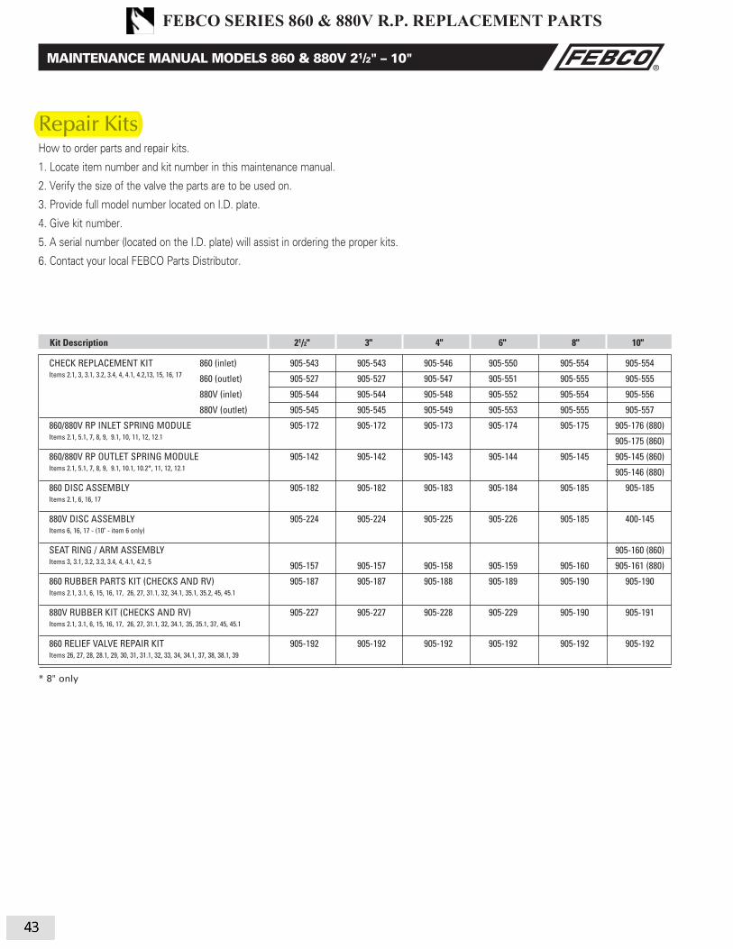
Repair KitsHow to order parts and repair kits.
1. Locate item number and kit number in this maintenance manual.
2. Verify the size of the valve the parts are to be used on.
3. Provide full model number located on I.D. plate.
4. Give kit number.
5. A serial number (located on the I.D. plate) will assist in ordering the proper kits.
6. Contact your local FEBCO Parts Distributor.
CHECK REPLACEMENT KIT 860 (inlet) 905-543 905-543 905-546 905-550 905-554 905-554
Items 2.1, 3, 3.1, 3.2, 3.4, 4, 4.1, 4.2,13, 15, 16, 17 860 (outlet) 905-527 905-527 905-547 905-551 905-555 905-555
880V (inlet) 905-544 905-544 905-548 905-552 905-554 905-556
880V (outlet) 905-545 905-545 905-549 905-553 905-555 905-557
860/880V RP INLET SPRING MODULE 905-172 905-172 905-173 905-174 905-175 905-176 (880)
Items 2.1, 5.1, 7, 8, 9, 9.1, 10, 11, 12, 12.1 905-175 (860)
860/880V RP OUTLET SPRING MODULE 905-142 905-142 905-143 905-144 905-145 905-145 (860)
Items 2.1, 5.1, 7, 8, 9, 9.1, 10.1, 10.2*, 11, 12, 12.1 905-146 (880)
860 DISC ASSEMBLY 905-182 905-182 905-183 905-184 905-185 905-185
Items 2.1, 6, 16, 17
880V DISC ASSEMBLY 905-224 905-224 905-225 905-226 905-185 400-145
Items 6, 16, 17 - (10" - item 6 only)
SEAT RING / ARM ASSEMBLY 905-160 (860)
Items 3, 3.1, 3.2, 3.3, 3.4, 4, 4.1, 4.2, 5 905-157 905-157 905-158 905-159 905-160 905-161 (880)
860 RUBBER PARTS KIT (CHECKS AND RV) 905-187 905-187 905-188 905-189 905-190 905-190
Items 2.1, 3.1, 6, 15, 16, 17, 26, 27, 31.1, 32, 34.1, 35.1, 35.2, 45, 45.1
880V RUBBER KIT (CHECKS AND RV) 905-227 905-227 905-228 905-229 905-190 905-191
Items 2.1, 3.1, 6, 15, 16, 17, 26, 27, 31.1, 32, 34.1, 35, 35.1, 37, 45, 45.1
860 RELIEF VALVE REPAIR KIT 905-192 905-192 905-192 905-192 905-192 905-192
Items 26, 27, 28, 28.1, 29, 30, 31, 31.1, 32, 33, 34, 34.1, 37, 38, 38.1, 39
Kit Description 21/2" 3" 4" 6" 8" 10"
* 8" only
14
MAINTENANCE MANUAL MODELS 860 & 880V 21/2" – 10"
IOM-F-860_880V.indd 14 7/11/08 10:45:29 AM
Repair Kits
FEBCO SERIES 860 & 880V R.P. REPLACEMENT PARTS
43
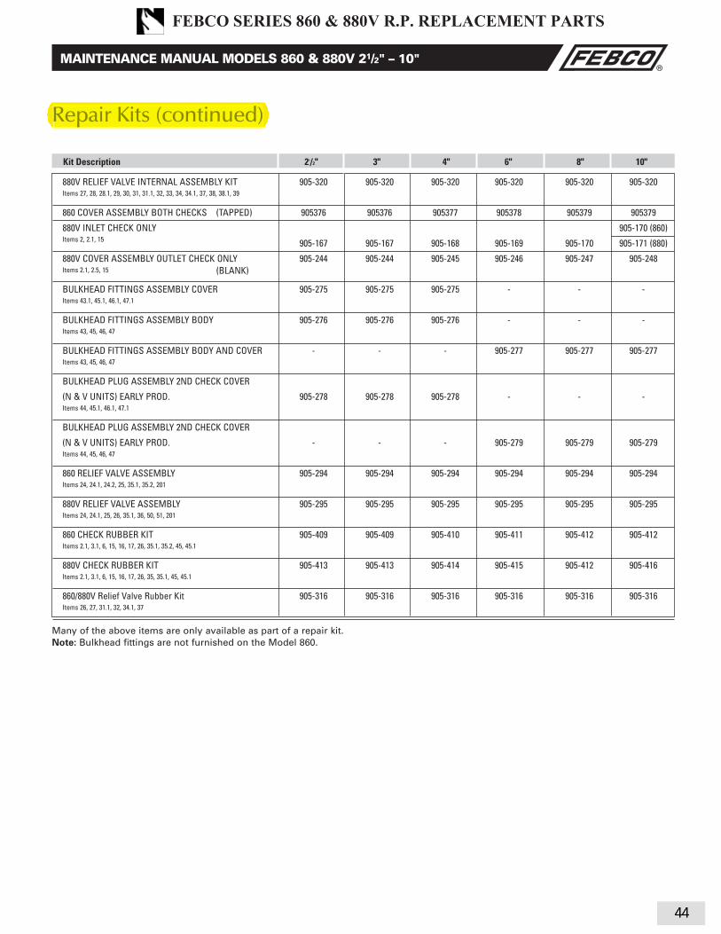
880V RELIEF VALVE INTERNAL ASSEMBLY KIT 905-320 905-320 905-320 905-320 905-320 905-320
Items 27, 28, 28.1, 29, 30, 31, 31.1, 32, 33, 34, 34.1, 37, 38, 38.1, 39
860 COVER ASSEMBLY BOTH CHECKS (TAPPED) 905376 905376 905377 905378 905379 905379
880V INLET CHECK ONLY 905-170 (860) Items 2, 2.1, 15 905-167 905-167 905-168 905-169 905-170 905-171 (880)
880V COVER ASSEMBLY OUTLET CHECK ONLY 905-244 905-244 905-245 905-246 905-247 905-248
Items 2.1, 2.5, 15
BULKHEAD FITTINGS ASSEMBLY COVER 905-275 905-275 905-275 - - -
Items 43.1, 45.1, 46.1, 47.1
BULKHEAD FITTINGS ASSEMBLY BODY 905-276 905-276 905-276 - - -
Items 43, 45, 46, 47
BULKHEAD FITTINGS ASSEMBLY BODY AND COVER - - - 905-277 905-277 905-277
Items 43, 45, 46, 47
BULKHEAD PLUG ASSEMBLY 2ND CHECK COVER
(N & V UNITS) EARLY PROD. 905-278 905-278 905-278 - - -
Items 44, 45.1, 46.1, 47.1
BULKHEAD PLUG ASSEMBLY 2ND CHECK COVER
(N & V UNITS) EARLY PROD. - - - 905-279 905-279 905-279
Items 44, 45, 46, 47
860 RELIEF VALVE ASSEMBLY 905-294 905-294 905-294 905-294 905-294 905-294
Items 24, 24.1, 24.2, 25, 35.1, 35.2, 201
880V RELIEF VALVE ASSEMBLY 905-295 905-295 905-295 905-295 905-295 905-295
Items 24, 24.1, 25, 26, 35.1, 36, 50, 51, 201
860 CHECK RUBBER KIT 905-409 905-409 905-410 905-411 905-412 905-412
Items 2.1, 3.1, 6, 15, 16, 17, 26, 35.1, 35.2, 45, 45.1
880V CHECK RUBBER KIT 905-413 905-413 905-414 905-415 905-412 905-416
Items 2.1, 3.1, 6, 15, 16, 17, 26, 35, 35.1, 45, 45.1
860/880V Relief Valve Rubber Kit 905-316 905-316 905-316 905-316 905-316 905-316
Items 26, 27, 31.1, 32, 34.1, 37
Kit Description 21/2" 3" 4" 6" 8" 10"
Many of the above items are only available as part of a repair kit.Note: Bulkhead fi ttings are not furnished on the Model 860.
Repair Kits (continued)
15
MAINTENANCE MANUAL MODELS 860 & 880V 21/2" – 10"
(BLANK)
IOM-F-860_880V.indd 15 7/11/08 10:45:29 AM
Repair Kits (continued)
FEBCO SERIES 860 & 880V R.P. REPLACEMENT PARTS
44

3
Service, Replacement Parts and Maintenance
NOTE: Before servicing be certain water is turned off or shutoff valves are closed
1. After removing the cover, remove the retainer for the body bore. The check valve modules can now be removed from the valve by hand or with a screwdriver.
Note: For Series 007 sizes 1⁄2" - 2" (15-50mm), the seats and springs of the first and second check modules are not inter-changeable. The heavier spring and smaller diameter seat belong with the first check module. Series 007M1 sizes 3⁄4" - 1" (20-25mm) and Series 007M2 3⁄4" (20mm) have interchangeable seats and springs.
2. The check seats are attached to the cage with a bayonet type locking arrangement. Holding the cage in one hand, push the seat inward and rotate clockwise against the cage, for 3⁄4" (20mm) Series 007M2 pull apart seat and cage. The seat, cage, spring and disc assembly are now individual components.
3. The disc assembly may now be cleaned and reassembled or, depending on its condition, it may be discarded and replace with a new assembly from the repair kit. O-rings should be cleaned or replaced as necessary.
4. Reassemble the check valve module in the reverse order. Check modules are installed in the valve body with the seats facing the valve inlet. The modules must be securely in place before the retainer can be replaced. On the 3⁄4" - 1" (20-25mm)size, this retainer may have to be tilted slightly into place. Replace cover.
1⁄2When ordering, specify ordering code number, kit number and valve size
Check Kits: 1st or 2nd Check
ORDERING CODE KIT NO. SIZE
in. mm
0887193 RK 007 CK4 1⁄2 15 0887026 RK 007M1 CK4 3⁄4 - 1 20-25 0887377 *RK SS007 CK4 1⁄2 15 0888070 *RK SS007M3 CK1 1⁄2 - 3⁄4 15-20 0888071 *RK SS007M3 CK2 1⁄2 - 3⁄4 15-20 0887393 *RK SS007M2 CK1 3⁄4 20 0887397 *RK SS007M2 CK2 3⁄4 20 0887373 *RK SS007M1 CK4 1 25
1st Check
0887023 RK 007 CK1 3⁄4 - 1 20-25 0887045 RK 007M2 CK1 3⁄4 20 0888550 RK 007M3 CK1 3⁄4 20 0887025 RK 007 CK1 11⁄2 - 2 40-50 0887186 RK 007M1 CK1 11⁄2 - 2 40-50 0887719 RK 007M2 CK1 11⁄4 - 11⁄2 32-40
2nd Check
0887024 RK 007 CK2 3⁄4 - 1 20-25 0887046 RK 007M2 CK2 3⁄4 20 0888551 RK 007M3 CK2 3⁄4 20 0887028 RK 007 CK2 11⁄2 - 2 32-50 0887187 RK 007M1 CK2 11⁄2 - 2 32-50 0887720 RK 007M2 CK2 11⁄4 - 11⁄2 32-40
Stainless Steel 1st or 2nd Check
0887022 RK 007 CK1 SS 3⁄4 - 1 20-25 0887030 RK 007 CK2 SS 3⁄4 - 1 20-25 0887032 RK 007M1 CK4 SS 3⁄4 - 1 20-25 0887031 RK 007 CK1 SS 11⁄2 - 2 40-50 0887035 RK 007 CK2 SS 11⁄2 - 2 40-50 0887189 RK 007M1 CK1 SS 11⁄2 - 2 40-50 0887190 RK 007M1 CK2 SS 11⁄2 - 2 40-50Kit includes: Seat, seat o-ring, disc assembly, spring, check cage,
cover o-ring.
Cover Kit
0887195 RK 007 C 1⁄2 15 0887036 RK 007 C 3⁄4 - 1 20-25 0887038 RK 007M1 C 3⁄4 - 1 20-25 0887039 RK 007M2 C 3⁄4 20 0888553 RK 007M3 C 3⁄4 20 0887037 RK 007 C 11⁄2 - 2 40-50 0887191 RK 007M1 C 11⁄2 - 2 40-50 0887722 RK 007M2 C 11⁄4 - 11⁄2 32-40 0887379 *RK SS007 C 1⁄2 15 0887380 *RK SS007M2 C 3⁄4 20 0888073 *RK SS007M3 C 1⁄2 - 3⁄4 15-20 0887381 *RK SS007M1 C 1 25Kit includes: Cover and cover o-ring
Complete Rubber Parts
0887194 RK 007 RT 1⁄2 15 0887040 RK 007 RT 3⁄4 - 1 20-25 0887042 RK 007M1 RT 3⁄4 - 1 20-25 0887043 RK 007M2 RT 3⁄4 20 0888552 RK 007M3 RT 3⁄4 20 0887041 RK 007 RT 11⁄2 - 2 40-50 0887188 RK 007M1 RT 11⁄2 - 2 40-50 0887721 RK 007M2 RT 11⁄4 - 11⁄2 32-40 0887378 *RK SS007 RT 1⁄2 15 0887394 *RK SS007M2 RT 3⁄4 20 0888072 *RK SS007M3 RT 1⁄2 - 3⁄4 15-20 0887374 *RK SS007M1 RT 1 25Kit includes: Cover o-ring, two seat discs and two seat o-rings.
*SS prefix denotes stainless steel body.
O-rings Check Cage
SpringDiscSeat
Cover
Cover O-ring
Retainer
Body
First C
heck
Second Check
Seat
Cover
Cover
O-ring
Retainer
Body
First C
heck
Second Check
Seat
O-ring
Disc
Assembly
Spring
Check
Cage
Complete Rubber Partsp
WATTS SERIES 007 D.C.REPLACEMENT PARTS LIST
45 45

Series 757, 757N, 757DCDA, LF757DCDA 757NDCDA, LF757NDCDA Repair Kits
ORDERING NO. SIZE DISC MODEL
in. mm
1st Check Kits
7018128 21⁄2 - 4 65-100 Red Silicone RK 757/757DCDA CK17018131 6 150 Red Silicone RK 757/757DCDA CK17018134 8 200 Red Silicone RK 757/757DCDA CK10899200 10 250 Red Silicone RK 757/757DCDA CK1
Kit consists of: First check module, Check module O-ring andDisc elastomer
2nd Check Kits
7018130 21⁄2 - 4 65-100 Red Silicone RK 757/757DCDA CK27018133 6 150 Red Silicone RK 757/757DCDA CK20899206 8 200 Red Silicone RK 757/757DCDA CK20899201 10 250 Red Silicone RK 757/757DCDA CK2
Kit consists of: Second check module, Check module O-ring andDisc elastomer
ORDERING NO. SIZE DISC MODEL
in. mm
1st or 2nd Check Rubber Parts Kits
0899202 21⁄2 - 4 65-100 Red Silicone RK 757/757DCDA RC4 0899203 6 150 Red Silicone RK 757/757DCDA RC4 0899204 8 200 Red Silicone RK 757/757DCDA RC4 0899205 10 250 Red Silicone RK 757/757DCDA RC4
Kit consists of: Check module O-ring, Disc elastomer and E-clip
Check Sleeve Cover Kits
0899211 21⁄2 - 4 65-100 – RK 757/757DCDA C 0899212 6 150 – RK 757/757DCDA C 0899213 8 200 – RK 757/757DCDA C 0899214 10 250 – RK 757/757DCDA C
Kit consists of: Closure sleeve, Sleeve O-ring and Gasket
Sleeve O-ring and Gasket
Check Module O-ring
First Check Module
Closure Sleeve Test Cock with O-ring
Closure Sleeve
E-clip
Disc Elastomer
Second Check Module
RP/IS-757/757DCDA 1018 EDP# 1915343 © 2010 Watts
USA: 815 Chestnut St., No. Andover, MA 01845-6098; www.watts.com
Canada: 5435 North Service Rd., Burlington, ONT. L7L 5H7; www.wattscanada.ca
A Watts Water Technologies Company
1st or 2nd Check Rubber Parts Kits
WATTS SERIES 757 D.C. 2.5" - 10" REPLACEMENT PARTS LIST
46

5
EDP NO KIT NO. SIZE
in. mm
0888820 RK 774/774DCDA CK 1 21⁄2 - 4 65 - 100 21⁄2"-4" 774/774DCDA / 6" 774X/774XDCDA 0888821 RK 774/774DCDA CK 1 6 150 6" 774/774DCDA / 8" 774X/774XDCDA
Kits include: Complete #1 Check with Check O-ring.
0888822 RK 774/774DCDA CK 2 21⁄2 - 4 65 - 100 21⁄2"-4" 774/774DCDA / 6" 774X/774XDCDA 0888823 RK 774/774DCDA CK 2 6 150 6" 774/774DCDA / 8" 774X/774XDCDA
Kits include: Complete #2 Check with Check O-ring.
0888824 RK 774/774DCDA C 21⁄2 - 4 65 - 100 21⁄2"-4" 774/774DCDA 0888825 RK 774/774DCDA C 6 150 6" 774/774DCDA / 8" 774X/774XDCDA 0888826 RK 774X/774XDCDA C 6 150 6" 774X/774XDCDA
Kit includes: Cover, Grooved Coupler & Gasket.
First Check Second Check
Watts Series 774/744DCDA 21⁄2"- 6"WATTS SERIES 774 D.C. REPLACEMENT PARTS LIST
47 47

6
EDP NO KIT NO. SIZE
in. mm
0888827 RK 774/774DCDA CK 4 8, 10, 12 200, 250, 300 774/774DCDA
Kits include: Complete Check with Check O-ring.
0888828 RK 774/774DCDA C 8, 10, 12 200, 250, 300 774/774DCDA
Kits include: Cover, Grooved Coupler & Gasket.
Watts assemblies require minimum maintenance. All assemblies must be retested once maintenance has been performed. (Before servicing be certain shut off valves are closed)
Check Studs Check Studs
#1 Cam-Check Figure 2 #2 Cam-Check Figure 3 Figure 4
Watts Series 774/744DCDA 8"- 12"
Servicing and Second Checks
1. Shut down water system and lock out system if possible. Slowly open all ball valves to relieve air and water pressure. Loosen bolts on groove coupler and remove groove couple and cover plate from valve body
2. #1 Check (Fig.2) Using a 9⁄16" socket wrench or nut driver, re-move the four nuts from the #1 check studs (See fig. 1) Using two hands, place them at 12 o'clock and 6 o'clock, wiggle the check assembly free. Remove through access port with back of clapper first with back of clapper first with spring end down. Pull check assembly out of main body. #2 Check (Fig.3) After loosening bolts with a 9⁄16" socket, remove bolts completely, Using the centerline access bar, spin the cam assembly from the 9 o'clock position to the 12 o'clock position, then (without letting go of the access bar)
push the cam assembly slightly downstream so that the clapper is now parallel to the valve body. Now bring the cam assembly through the check retaining wall. Leave the cam assembly clapper parallel to the valve body. Pull the cam assembly through the access port.
3. Using a 3⁄8" nut driver or a piece of small diameter pipe, place on the cam arm torsion spring and move away from and around the torsion spring retaining bracket so as to relieve the torsion spring tension. (See Figure 4) This will allow the cam arm to move freely, enabling you to inspect the clapper face and cam seat.Thoroughly clean the seat area and clapper sealing surfaces, cam arms, and O-rings.
4. Before reinstallation of Checks thoroughly clean O-ring groove and lubricate O-ring with F.D.A. approved lubricant.
WATTS SERIES 774 D.C. REPLACEMENT PARTS LIST
48 48

4
709 3/4" – 2" EDP No. Kit No. Size
First or Second Check Kits in. mm
0887150 RK 709 CK4 3⁄4 – 1 20-25 0887151 RK 709 CK4 11⁄2 – 2 32-50 0887154 RK 709 CK4SS* 3⁄4 – 1 20-25 0887155 RK 709 CK4SS* 11⁄2 – 2 32-50Kit includes: Disc assembly, Spring, Seat, Seat o-ring and Cover O-ring.
Complete Rubber Parts
0887152 RK 709 RT 3⁄4 – 1 20-25 0887153 RK 709 RT 11⁄2 – 2 32-50Kit includes: Diaphragm, Disc assembly, Seat o-ring and Cover o-ring.
Seat Kits
0887160 RK 709 S4 3⁄4 – 1 20-25 0887161 RK 709 S4 11⁄2 – 2 32-50 0887162 RK 709 S4SS* 3⁄4 – 1 20-25 0887163 RK 709 S4SS* 11⁄2 – 2 32-50
Cover Kits
0887156 RK 709 C1 3⁄4 – 1 20-25 0887157 RK 709 C1 11⁄2 – 2 32-50 0887158 RK 709 C2 3⁄4 – 1 20-25 0887159 RK 709 C2 11⁄2 – 2 32-50Kit includes: Cover and Cover o-ring.
*Stainless Steel
1. After removing the cover screw, the check comes out with the cover.2. Holding the check Valve module in both hands, rotate the assembly 1⁄4 turn. This will disengage the disc and spring assembly into individual components. The disc assembly may be cleaned or replaced. O-rings should be cleaned or replaced as necessary and lightly greased with the FDA approved silicon grease. Reassemble the check valve module in the reverse order. NOTE: The springs of the first and second check valves are interchangeable. (Before servicing, be certain water is turned off or shutoff valves are closed)
First Check Second Check
Cover
Cover
O-ring
Spring
Disc
Holder
Assembly
Seat
Seat
O-ring
Rubber PartsKit
First CheckKit
Second CheckKit
Rubber Parts
Kit
3/4" – 2" (20-50mm)
Complete Rubber Parts
WATTS SERIES 709 D.C. & D.C.D.A.REPLACEMENT PARTS LIST
49

5
1. Remove hatch cover bolts. NOTE: The 709 is designed so that, when the bolts are backed off 1⁄2", all the spring load is released f ro m t h e c o v e r a n d re t a i n e d b y t h e c h e c k m o d u l e . CAUTION: Be sure to verify this before removing all the bolts.
2. Lift check valve module straight out, taking care not to hit anddamage seat ring.
3. The seat ring may be removed and replaced by pulling out the two wire retainers. The wire retainers are 10" long. One is drawn out clockwise and the other is drawn out counterclockwise.
4. With the retainer wires removed, the seat ring can be lifted straight up and removed.
CAUTION: The check valve disc and spring assembly are in compression. The spring load is captured by the two spring retainers and the stem The spring retainers are not to be removed for servicing. If there is a need to replace the spring, spring retainer or stem, replace the disc and spring assembly. If the disc holder has been damaged by freezing or severe water hammer, it can be replaced in the field. Remove the disc holder retaining ring and slide the disc holder off the stem. Remover the o-ring from the stem and replace with a new one. Apply grease to the o-ring and slide the new disc holder into place. Re-install the retaining ring. NOTE: The disc holder should not be removed when servicing only the disc, remove allen head screws holding the disc retaining plate and replace disc.
709 21⁄2" – 10" (65-250mm)EDP No. Kit No. Size
First or Second Check Kits in mm
0887900 RK 709 CK4 21⁄2 – 3 65-80 0887901 RK 709 CK4 4 100 0887902 RK 709 CK4 6 150 0887903 RK 709 CK4 8 2000887904 RK 709 CK4 10 300
Kit includes: Disc & spring assembly and Cover O-ring.
Rubber Parts (for one check)
0887905 RK 709 RC4 21⁄2 – 3 65-80 0887906 RK 709 RC4 4 100 0887907 RK 709 RC4 6 150 0887908 RK 709 RC4 8 2000887909 RK 709 RC4 10 250
Kit includes: Disc and Cover O-ring.
Complete Rubber Parts
0887915 RK 709 RT 21⁄2 – 3 65-80 0887916 RK 709 RT 4 100 0887917 RK 709 RT 6 150 0887918 RK 709 RT 8 2000887919 RK 709 RT 10 250
Kit includes: Two discs and Two Cover O-rings.
Seat Kits
0887910 RK 709S 21⁄2 – 3 65-80 0887911 RK 709S 4 100 0887912 RK 709S 6 150 0887913 RK 709S 8 2000887914 RK 709S 10 250
Kit includes: Seat, Seat o-ring, Retainer Wire and Cover O-ring.
Cover Kits
0887920 RK 709 C 21⁄2 – 3 65-80 0887921 RK 709 C 4 100 0887922 RK 709 C 6 150 0887923 RK 709 C 8 2000887924 RK 709 C 10 250
Kit includes: Cover and Cover O-ring.
709DCDA 3" – 10" (80-250mm) EDP No. Kit. No. Size
First Check Kits in mm
0887930 RK 709DCDA CK1 3 80 0887931 RK 709DCDA CK1 4 100 0887932 RK 709DCDA CK1 6 150 0887933 RK 709DCDA CK1 8 200 0887934 RK 709DCDA CK1 10 250
Second Check Kits
0887935 RK 709DCDA CK2 3 80 0887936 RK 709DCDA CK2 4 100 0887937 RK 709DCDA CK2 6 150 0887938 RK 709DCDA CK2 8 200 0887939 RK 709DCDA CK2 10 250Kit includes: Disc assembly, Spring assembly and Cover O-ring.
Rubber Parts (for one check)
0887940 RK 709DCDA RC4 3 80 0887941 RK 709DCDA RC4 4 100 0887942 RK 709DCDA RC4 6 150 0887943 RK 709DCDA RC4 8 200 0887944 RK 709DCDA RC4 10 250Kit includes: Disc and Cover O-ring.
Seat Kits
0887945 RK 709DCDA S 3 80 0887946 RK 709DCDA S 4 100 0887947 RK 709DCDA S 6 150 0887948 RK 709DCDA S 8 200 0887949 RK 709DCDA S 10 250Kit includes: Seat, Retainer Wire and Cover O-ring.
Cover Kits
0887950 RK 709DCDA C 3 80 0887951 RK 709DCDA C 4 100 0887952 RK 709DCDA C 6 150 0887953 RK 709DCDA C 8 200 0887954 RK 709DCDA C 10 250Kit includes: Cover and Cover O-ring.
Spring Retainer
(Do Not Remove)
Spring
O-ring
Spring Retainer
(Do Not Remove)
Disc
Disc Holder
Retaining Ring
Disc RetainerAllen Head
Socket Screws
Stem
Disc Holder
*Warning: Spring assemblyis factory assembled. DO NOTDISASSEMBLE.
21⁄2", 3" (65-80mm)
4" - 10" (100-250mm)
Cover
Cover
O-ring
*Disc &
Spring
Assembly
Seat
Seat
O-ring
Retainer Wire
Seat
Second
Check
First
Check
Cover
O-ringO-ring
1/2" – 10" (65-250mm)
Complete Rubber PartsRubber Parts (for one check)
Rubber Parts (for one check)
WATTS SERIES 709 D.C. & D.C.D.A.REPLACEMENT PARTS LIST
50

Servicing First &Second Check Valves1⁄4" – 2" (8 – 50mm)
11⁄4" - 2" (32 – 50mm)ORDERING CODE KIT NO. SIZE
First Check Kit: inch mm0887300 RK 009M2 CK1 11⁄4 – 11⁄2 32-400887270 RK 009M1 CK1 11⁄4 – 2 32-500887006 RK 009 CK1 11⁄4 – 2 32-500887010 RK 009 CK1SS 11⁄4 – 2 32-500887272 RK 009MI CK1SS 11⁄4 – 2 32-500887540 RK 009M2 CK1 2 50
Kit consists of: First check assembly, Cover O-ring and Sensing passage O-ring.
Second Check Kit:0887301 RK 009M2 CK2 11⁄4 – 11⁄2 32-400887271 RK 009M1 CK2 11⁄4 – 2 32-500887008 RK 009 CK2 11⁄4 – 2 32-500887012 RK 009 CK2SS 11⁄4 – 2 32-500887273 RK 009 M1 CK2SS 11⁄4 – 2 32-500887541 RK 009M2 CK2 2 50
Kit consists of: Second check assembly, Cover O-ring and Sensing passage O-ring.
First Check Rubber Parts Kit:0887304 RK 009M2 RC1 11⁄4 – 11⁄2 32-400887274 RK 009M1 RC1 11⁄4 – 2 32-500887018 RK 009 RC1 11⁄4 – 2 32-500887542 RK 009M2 RC1 2 50
Kit consists of: First check assembly O-ring, Disc holder assembly, Cover O-ring andSensing passage O-ring.
Second Check Rubber Parts Kit:0887305 RK 009M2 RC2 11⁄4 – 11⁄2 32-400887275 RK 009M1 RC2 11⁄4 – 2 32-500887183 RK 009 RC2 11⁄4 – 2 32-500887543 RK 009M2 RC2 2 50
Kit consists of: Second check assembly O-ring, Disc holder assembly, Cover O-ringand Sensing passage O-ring.
1⁄4" – 1" (8 – 25mm)
ORDERING CODE KIT NO. SIZE
First Check Kits: inch mm0887291 RK 009 CK1 1⁄4, 3⁄8, 1⁄2 8, 10, 150887505 RK SS009 CK1 1⁄2 150887000 RK 009M2 CK1 3⁄4 200887515 RK SS009M3 CK1 1⁄4 – 3⁄4 8-200888520 RK 009M3 CK1 3⁄4 200887005 RK 009 CK1 3⁄4 – 1 20-250887009 RK 009 CK1SS 3⁄4 – 1 20-250887525 RK SS009 CK1 1 250887789 RK 009M2 CK1 1 25
Kit consists of: Check assembly and Cover O-ring.
Second Check Kits:0887292 RK 009 CK2 1⁄4, 3⁄8, 1⁄2 8, 10, 150887506 RK SS009 CK2 1⁄2 150887001 RK 009M2 CK2 3⁄4 200887516 RK SS009M3 CK2 1⁄4 – 3⁄4 8, 10, 150888521 RK 009M3 CK2 3⁄4 150887007 RK 009 CK2 3⁄4 – 1 15-250887011 RK 009 CK2SS 3⁄4 – 1 15-250887526 RK SS009 CK2 1 250887790 RK 009M2 CK2 1 25
Kit consists of: Check assembly and Cover O-ring.
Check Rubber Parts:0887293 RK 009 RC3 1⁄4, 3⁄8, 1⁄2 8, 10, 150887003 RK 009M2 RC3 3⁄4 200888522 RK 009M3 RC3 3⁄4 200887507 RK SS009 RC1 1⁄2 150887517 RK SS009M2 RC1 3⁄4 200888595 RK SS009M3 RC1 1⁄4 – 3⁄4 8-200887017 RK 009 RC1 3⁄4 – 1 20-250887527 RK SS009 RC1 1 250887791 RK 009M2 RC1 1 250887508 RK SS009 RC2 1⁄2 150887518 RK SS009M2 RC2 3⁄4 200888596 RK SS009M3 RC2 1⁄4 – 3⁄4 8-200887180 RK 009 RC2 3⁄4 – 1 20-250887528 RK SS009 RC2 1 250887792 RK 009M2 RC2 1 25
Kit consists of: Disc, Cover O-ring and Seat O-ring.
Retainers:1047053 99AB47 1⁄4, 3⁄8, 1⁄2 8, 10, 151047394 99BA47 M2-M3 3⁄4 201047001 99FA47 11⁄4 – 2 32-501047001 99FA47 M1, 2" M2 11⁄4 – 2 32-501047401 99EA47 M2 11⁄4 – 11⁄2 32-40
1. Remove the retainer from the body bore. The check valvemodules can now be removed from the valve by hand orwith a screwdriver. Note: The seats and springs of the firstand second check modules are not interchangeable. Theheavier spring and smaller diameter seat belong with the firstcheck module.
2. The check seats are attached to the cage with a bayonettype locking arrangement. Holding the cage in one hand,push the seat inward and rotate clockwise against the cage.The seat, spring cage, spring and disc assembly are now in-dividual components.
Note: 3⁄4" M2 modules snap apart.
3. The disc assembly may now be cleaned and re-assembledor, depending on its condition, may be discarded andreplaced with a new assembly from the repair kit. O-ringsshould be cleaned or replaced as necessary and lightlygreased with the FDA approved grease. Refer to parts pricelist, PL-RP-BPD for more information.
4. Re-assemble the check valve modules. Check modules areinstalled in the valve body with the seat facing the valve inlet.The modules must be securely in place before the retainercan be replaced. On the 3⁄4" size retainer may have to be tilt-ed slightly into place. Replace relief valve assembly.
CHECK ASSEMBLY 1" - 2" (25 – 50mm)
CHECK ASSEMBLY 1⁄4" – 3⁄4"CHECK ASSEMBLY 3⁄4" M3
Watts reserves the right to change or modify product design, construc-
tion, specifications, or materials without prior notice and without incur-
ring any obligation to make such changes and modifications on Watts
products previously or subsequently sold.
Injection MoldedAcetyl Resin
O-ring Seal
Stainless SteelSpring
Silicone Seal1st CheckModule
Seat
Seat O-ring Disc AssemblySpring
Check Cage
Cover O-ring
Retainer
Second Check Assembly
First Check Assembly
ReliefValve
Module
5For additional information, contact your local technical sales representative, see back page.
O-ring Seal
SpringDiscSeat
CheckCage
Replacement Parts — 1⁄4" – 2" (8 – 50mm)When ordering, specify Ordering Code, Kit number and Valve Size.
Check Rubber Parts:
First Check Rubber Parts Kit:
Second Check Rubber Parts Kit:
WATTS SERIES 009 R.P. REPLACEMENT PARTS LIST
51

Servicing the Relief Valve 1⁄4" – 2" (8 – 50mm)
Replacement Parts — 1⁄4" – 2" (8 – 50mm)When ordering, specify Ordering Code, Kit number and Valve Size.
11⁄4" – 2" (32 – 50mm)ORDERING CODE KIT NO. SIZE
Relief Valve Total Kit: inch mm0887307 RK 009M2 VT 11⁄4 – 11⁄2 32-400887277 RK 009M1 VT 11⁄4 – 2 32-500887016 RK 009 VT 11⁄4 – 2 32-500887545 RK 009M2 VT 2 50
Kit consists of: RV assembly, Seat, Seat O-ring, Cover O-ring, Sensing passage O-ringand Upper stem O-ring.
Relief Valve Rubber Parts Kit:0887306 RK 009M2 RV 11⁄4 – 11⁄2 32-400887276 RK 009M1 RV 11⁄4 – 2 32-500887184 RK 009 RV 11⁄4 – 2 32-500887544 RK 009M2 RV 2 50
Kit consists of: Diaphragm, Seat O-ring, Cover O-ring and Sensing passage O-ring.
Complete Rubber Parts Kit:0887309 RK 009M2 RT 11⁄4 – 11⁄2 32-400887280 RK 009M1 RT 11⁄4 – 2 32-500887185 RK 009 RT 11⁄4 – 2 32-500887547 RK 009M2 RT 2 50
Kit consists of: Two check assembly O-rings, Two disc assemblies, One cover O-ring,One RV diaphragm, One RV seat O-ring, One sensing passage O-ring, One diaphragmplate O-ring, One RV lower stem O-ring, One RV upper stem O-ring, One RV discassembly and One bleed screw O-ring.
Cover Kit:0887308 RK 009M2 C 11⁄4 – 11⁄2 32-400887278 RK 009M1 C 11⁄4 – 2 32-500887014 RK 009 C 11⁄4 – 2 32-500887546 RK 009M2 C 2 5
Kit consists of: Cover, Cover O-ring, Sensing passage O-ring, Bleed screw O-ring,Vent hood and Bleed screw.
1⁄4" – 1" (8 – 25mm)
ORDERING CODE KIT NO. SIZE
Relief Valve Kits: inch mm0887294 RK 009 VT 1⁄4, 3⁄8, 1⁄2 8, 10, 150887509 RK SS009 VT 1⁄2 150887002 RK 009M2 VT 3⁄4 200887520 RK SS009M2/M3 VT 1⁄4 – 3⁄4 8-200888524 RK 009M3 VT 3⁄4 200887015 RK 009 VT 3⁄4 – 1 20-250887503 RK SS009 VT 1 250887785 RK 009M2 VT 1 25
Kit consists of: Seat, Seat O-ring, Stem & diaphragm assembly, Stem O-ring, Cover O-ring and RV spring.
Relief Valve Rubber Parts Kits:0887295 RK 009 RV 1⁄4, 3⁄8, 1⁄2 8, 10, 150887510 RK SS009 RV 1⁄2 150886998 RK 009M2 RV 3⁄4 200887519 RK SS009M2/M3 RV 1⁄4 – 3⁄4 8-200888523 RK 009M3 RV 3⁄4 200887181 RK 009 RV 3⁄4 – 1 20-250887529 RK SS009 RV 1 250887786 RK 009M2 RV 1 25
Kit consists of: Diaphragm, Disc assembly, Stem O-rings, Seat O-ring and Cover O-ring.
Total Rubber Parts Kits:0887297 RK 009 RT 1⁄4, 3⁄8, 1⁄2 8, 10, 150887511 RK SS009 RT 1⁄2 150886999 RK 009M2 RT 3⁄4 200887521 RK SS009M2 RT 3⁄4 200888526 RK 009M3 RT 3⁄4 200888597 RK SS009M3 RT 1⁄4 – 3⁄4 8-200887182 RK 009 RT 3⁄4 – 1 20-250887530 RK SS009 RT 1 250887787 RK 009M2 RT 1 2
Kit consists of: Diaphragm, Two discs, Two disc assemblies, Stem O-rings, Cover O-ring, Two seat O-rings and RV seat O-ring.
Cover Kits:0887296 RK 009 C 1⁄4, 3⁄8, 1⁄2 8, 10, 150887500 RK SS009 C 1⁄2 150887004 RK 009M2 C 3⁄4 200887501 RK SS009M2/M3 C 1⁄4 – 3⁄4 8-200888525 RK 009M3 C 3⁄4 200887013 RK 009 C 3⁄4 – 1 20-250887502 RK SS009 C 1 250887788 RK 009M2 C 1 2
Kit consists of: Cover and Cover O-ring.
1. Remove the relief valve cover bolts while holding the cover down.
2. Lift the cover straight off. The stem and diaphragm assem-bly will normally remain with the cover as it is removed. Therelief valve spring will be free inside the body at this point.
3. The relief valve seat is located at the bottom of the bodybore and can be removed, if necessary, for cleaning. Thedisc can be cleaned without disassembly of the relief valvemodule. If it is determined that the relief valve diaphragmand/or disc should be replaced, the relief valve module canbe readily disassembled without the use of special tools.Note: the disc rubber is molded into the disc holder and issupplied as a disc holder assembly.
4. To re-assemble the relief valve, press the seat firmly intoplace in the body, center the spring on the seat, and insertthe cover and relief valve module as a unit straight into thebore. Press down on the cover to assure proper alignment.Insert and tighten bolts.
Caution: If cover will not press flat against body, stem as-sembly is crooked and damage can result. Re-align stemand cover before bolts are inserted.
Test Cock No.3Test Cock No.2Test Cock No.4
First CheckModule
Assembly Second CheckModule
AssemblyRelief ValveAssembly
Water Outlety
Water Outlet
Cover
Cover O-ring
Diaphragm
Stem & DiaphragmAssembly
Retainer
Seat
Seat O-ring
Body
Rel
ief
Valv
eS
ervi
ce P
arts
Kit
For additional information, contact your local technical sales representative, see back page.4
Total Rubber Parts Kits:
Complete Rubber Parts Kit:p
WATTS SERIES 009 R.P. RELIEF VALVE REPLACEMENT PARTS LIST
52

1. Remove the four screws holding the first check valve cover.
2. Lift off the first check valve cover. The check valve inside will come out with the cover and is attached with a bayonet type locking arrangement.3. Holding the check valve module in both hands, rotate the assembly quarter turn. This will disengage the disc assembly, spring and seat cover into individual components.4. The disc assembly may be cleaned and reassembled, or depending upon its condition, it may be discarded and replaced with a new assembly from the service kit. O-rings should be cleaned or replaced as necessary and lightly greased with the FDA approved silicon grease which is also furnished with the service kit.5. Reassemble the check valve module in the reverse order. Service is identical for both the first and second check valves.
Cover
Cover
O-ring
Spring
Disc
Assembly
Seat
Seat
O-ring
Note: The springs and covers of the
first and second check valves are not interchangeable. The heavier spring loaded
module should be in the first check and the
lighter in the second check module.
When ordering, specify Ordering Code Number, Kit Number† and Valve Size
First Check Kits Order No. Kit. No. Sizes in. mm 0887120 RK 909 CK1 3⁄4 – 1 20-25 0887133 RK 909 CK1 11⁄4 – 2 32-50 0887122 RK 909 CK1SS* 3⁄4 – 1 20-25 0887135 RK 909 CK1SS* 11⁄4 – 2 32-50Kit includes: Disc assembly, Spring, Seat, Seat o-ring, Cover o-ring and lubricant. *Stainless Steel Seat.Second Check Kits 0887121 RK 909 CK2 3⁄4 – 1 20-25 0887134 RK 909 CK2 11⁄4 – 2 32-50 0887123 RK 909 CK2SS* 3⁄4 – 1 20-25 0887136 RK 909 CK2SS* 11⁄4 – 2 32-50Kit includes: Disc assembly, Spring, Seat, Seat o-ring, Cover o-ring and lubricant. *Stainless Steel Seat.Rubber Parts for Both Checks 0887129 RK 909 RC3 3⁄4 – 1 20-25 0887142 RK 909 RC3 11⁄4 – 2 32-50 0887310 RK 909 RC3 HW 3⁄4 – 1 20-25 0887311 RK 909 RC3 HW 11⁄4 – 2 32-50Kit includes: Check discs, Seat o-rings, Cover o-rings and lubricant. HW model has bronze disc. †Note: 11⁄4" – 2" (32-50mm) 909/909M1 share a common kit.
Complete Rubber Parts Order No. Kit No. Size in. mm 0887130 RK 909 RT 3⁄4 – 1 20-25 0887144 RK 909 RT 11⁄4 – 2 32-50Kit includes: Check discs, Seat o-rings, RV diaphragm, RV o-rings, Piston o-rings, Cover o-rings and lubricant.Seat Kits for One Check 0887124 RK 909 S 3⁄4 – 1 20-25 0887139 RK 909 S 11⁄4 – 2 32-50 0887125 RK 909 S-SS* 3⁄4 – 1 20-25 0887140 RK 909 S-SS* 11⁄4 – 2 32-50Kit includes: Seat, Seat o-ring and lubricant. *Stainless Steel Seat.Cover Kits 0887127 RK 909 C1 3⁄4 – 1 20-25 0887128 RK 909 C2 3⁄4 – 1 20-25 0887132 RK 909 VC 3⁄4 – 1 20-25 0887137 RK 909 C4 11⁄4 – 2 32-50 0887143 RK 909 VC 11⁄4 – 2 32-50Kit includes: Cover, Cover o-ring and lubricant.
For other repair kits and parts send for PL-RP-BPD. 5
First Check Second Check
Servicing First and Second Check Valves 3/4" to 2" (20 to 50mm)
3/4
First Check
Service Parts Kit
Second Check
Service Parts KitBody
Note:
No special tools required to service
Series 909
Relief Valve
Service Parts Kit
For further details contact your local technical sales representative, see back page.
Rubber Parts for Both Checks
Complete Rubber Partsp
WATTS SERIES 909 R.P. REPLACEMENT PARTS LIST
53
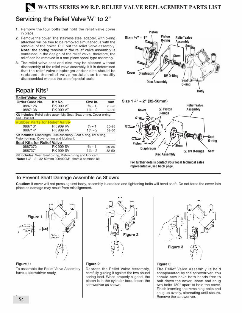
1. Remove the four bolts that hold the relief valve cover in place.2. Remove the cover. The stainless steel adapter, with o-ring attached will be free to be removed simultaneous with the removal of the cover. Pull out the relief valve assembly. Note: the spring tension in the relief valve assembly is contained in the design of the relief valve; therefore, the relief can be removed in a one-piece spool-type assembly.3. The relief valve seat and disc may be cleaned without disassembly of the relief valve assembly. If it is determined that the relief valve diaphragm and/or disc should be replaced, the re l ief valve module can be readi ly disassembled without the use of special tools.
†
Relief Valve Kits Order Code No. Kit No. Size in. mm 0887126 RK 909 VT 3⁄4 – 1 20-25 0887138 RK 909 VT 11⁄4 – 2 32-50Kit includes: Relief valve assembly, Seat, Seat o-ring, Cover o-ring and lubricant.Rubber Parts for Relief Valve 0887131 RK 909 RV 3⁄4 – 1 20-25 0887141 RK 909 RV 11⁄4 – 2 32-50Kit includes: Diaphragm, Disc assembly, Seat o-ring, RV o-ring, Piston o-rings, Cover o-ring and lubricant.Seat Kits for Relief Valve 0887372 RK 909 SV 3⁄4 – 1 20-25 0887371 RK 909 SV 11⁄4 – 2 32-50Kit includes: Seat, Seat o-ring, Piston o-ring and lubricant. †Note: 11⁄4" - 2" (32-50mm) 909/909M1 share a common kit.
Caution: If cover will not press against body, assembly is crooked and tightening bolts will bend shaft. Do not force the cover into place as damage may result from misalignment.
Figure 1
Figure 2
Figure 3
Figure 1:
To assemble the Relief Valve Assembly have a screwdriver ready.
Figure 2:
Depress the Relief Valve Assembly, carefully guiding it against the two pound spring load. When properly aligned, the piston is in the cylinder bore. Insert the screwdriver as shown.
Figure 3:
The Relief Valve Assembly is held encapsulated by the screwdriver. You should now have both hands free to bolt down the cover. Insert and snug two bolts 180° apart to hold the cover. Finish inserting the remaining bolts and snug up evenly, alternating until secure. Remove the screwdriver.
Disc Assembly
Piston
O-ringRelief Valve
Assembly
RV O-Ring
Stem
Seat
Body
Cover
Diaphragm
Piston
6
Cover
Seat
O-ring
Size 3⁄4” – 1”
Disc Assembly
(2) Piston
O-rings
Relief Valve
Assembly
(2) RV O-Rings
Stem
SeatDiaphragm
Piston
Seat
O-ring
Size 11⁄4" – 2" (32-50mm)
For further details contact your local technical sales
representative, see back page.
Servicing the Relief Valve 3/4" to 2"
Rubber Parts for Relief Valve
WATTS SERIES 909 R.P. RELIEF VALVE REPLACEMENT PARTS LIST
54

Servicing First and Second ChecksSizes: 21⁄2" – 10" (65-250mm)
1. Remove the hatch cover bolts. NOTE: The 909 is designed sothat when the bolts are backed off 1⁄2", all the spring load isreleased from the cover and retained by the check module.CAUTION: Be sure to verify this before removing all the bolts.
2. Lift the check valve module straight out taking care not to hit anddamage the seating.
3. The seat ring may be removed and replaced by pulling out thetwo wire retainers on sizes 4" – 10" (100 – 250) while on sizes21⁄2" – 3" (65 – 80mm), one quarter turn twist removes seat.The wire retainers are 10" long. One is drawn out clockwiseand the other is drawn out counterclockwise.
4. With the retainer wires removed, the seat ring can be liftedstraight up and removed.
5. CAUTION: The check valve spring is in compression. The springload is captured by the two spring retainers and the stem. Thespring retainers are not to be removed for servicing. If there is aneed to replace the spring, spring retainer or stem, an assembledmodule must be obtained from the factory. These modules arenot interchangeable, be sure to replace the first check with a firstcheck module and the second check with a second check module.
6. To replace the disc on sizes 21⁄2" – 4" (65 – 100mm) simplyremove the retaining nut or for sizes 6" – 10" (150 – 250mm)remove the allen head socket screws. Reverse this procedure toinstall the new disc.
909 Repair Kits 21⁄2" – 10" (65 – 250mm)
ORDERING CODE KIT NO. SIZE
First Check Kits: in. mm0887210 RK 909 CK1 21⁄2 – 3 65-800887212 RK 909 CK1 4 1000887213 RK 909 CK1 6 1500887214 RK 909 CK1 8 2000887215 RK 909 CK1 10 250
Second Check Kits:
0887211 RK 909 CK2 21⁄2 – 3 65-800887216 RK 909 CK2 4 1000887217 RK 909 CK2 6 1500887218 RK 909 CK2 8 2000887219 RK 909 CK2 10 250
Kits include: Disc & Spring assembly, Cover O-ring and lubricant.
First Check Rubber Parts Kits:
0887220 RK 909 RC1 21⁄2 – 3 65-800887221 RK 909 RC1 4 1000887223 RK 909 RC1 6 1500887224 RK 909 RC1 8 2000887225 RK 909 RC1 10 250
Second Check Rubber Parts Kits:
0887226 RK 909 RC2 21⁄2 – 3 65-800887227 RK 909 RC2 4 1000887228 RK 909 RC2 6 1500887229 RK 909 RC2 8 2000887230 RK 909 RC2 10 250
Kits include: Lower Stem O-ring (6" only), Check disc, Cover O-ring, and lubricant.
Seat Kits for Checks:
0887730 RK 909 S 21⁄2 – 3 65-800887731 RK 909 S 4 1000887732 RK 909 S 6 1500887733 RK 909 S 8 2000887734 RK 909 S 10 250
Kits include: Seat, Seat O-ring, Cover O-ring, Retainer wire and lubricant.
Total Rubber Parts Kits:
0887750 RK 909 RT 21⁄2 – 3 65-800887751 RK 909 RT 4 1000887752 RK 909 RT 6 1500887753 RK 909 RT 8 2000887754 RK 909 RT 10 2500887761 RK 909M1 RT 8 2000887762 RK 909M1 RT 10 250
Kits include: Lower Stem O-ring (6" only), Check disc, Cover O-ring, Sleeve O-ring,Piston O-ring, RV disc assembly, Diaphragm, Piston seal and Lubricant.When ordering specify EDP number, Kit Number and Valve Size.
909RPDA Repair Kits 21⁄2" – 10" (65 – 250mm)
ORDERING CODE KIT NO. SIZE
First Check Kits: in. mm0887239 RK 909RPDA CK1 21⁄2 – 3 65-800887240 RK 909RPDA CK1 4 1000887241 RK 909RPDA CK1 6 1500887242 RK 909RPDA CK1 8 2000887243 RK 909RPDA CK1 10 250
Second Check Kits:
0887244 RK 909RPDA CK2 21⁄2 – 3 65-800887245 RK 909RPDA CK2 4 1000887246 RK 909RPDA CK2 6 1500887247 RK 909RPDA CK2 8 2000887248 RK 909RPDA CK2 10 250
Kits include: Disc & Spring assembly, Cover O-ring and lubricant.
First Check Rubber Parts Kits:
0887249 RK 909RPDA RC1 21⁄2 – 3 65-800887250 RK 909RPDA RC1 4 1000887251 RK 909RPDA RC1 6 1500887252 RK 909RPDA RC1 8 2000887253 RK 909RPDA RC1 10 250
Second Check Rubber Parts Kits:
0887254 RK 909RPDA RC2 21⁄2 – 3 65-800887255 RK 909RPDA RC2 4 1000887256 RK 909RPDA RC2 6 1500887257 RK 909RPDA RC2 8 2000887258 RK 909RPDA RC2 10 250
Kits include: Lower Stem O-ring (6" only), Check disc, Cover O-ring, and lubricant.
Seat Kits for Checks:
0887735 RK 909RPDA S 21⁄2 – 3 65-800887736 RK 909RPDA S 4 1000887737 RK 909RPDA S 6 1500887738 RK 909RPDA S 8 2000887739 RK 909RPDA S 10 250
Kits include: Seat, Seat O-ring, Cover O-ring, Retainer wire and lubricant.
Total Rubber Parts Kits:
0887756 RK 909RPDA RT 21⁄2 – 3 65-800887757 RK 909RPDA RT 4 1000887758 RK 909RPDA RT 6 1500887759 RK 909RPDA RT 8 2000887760 RK 909RPDA RT 10 2500887764 RK 909RPDAM1 RT 8 2000887765 RK 909RPDAM1 RT 10 250
Kits include: Lower Stem O-ring (6" only), Check disc, Cover O-ring, Sleeve O-ring,Piston O-ring, RV disc assembly, Diaphragm, Piston seal and Lubricant.
NOTE:No special tools
required to serviceSeries 909
First and second checksare not interchangeable
FirstCheck
SecondCheckRelief
Valve
When ordering specify EDP number, Kit Num
*Warning: Spring assembly is factory assembled. DO NOT DISASSEMBLE
*Disc & Spring
Assembly
SeatSeat O-ring
Cover O-ring
21⁄2" – 3"(65 – 80mm) *Disc & Spring
Assembly
Retainer wire
Seat O-ringCover O-ring
4" – 10" (100 – 250mm)
Lower StemO-ring (6" only)Seat
Disc
For further details contact your technical sales representative, see back page.
909OSY
5
Total Rubber Parts Kits:
Total Rubber Parts Kits:
WATTS SERIES 909 R.P. 2.5" - 10" REPLACEMENT PARTS LIST
55

Servicing the Relief ValveSizes: 21⁄2" – 10" (65-250mm)1. Remove the relief valve cover bolts. Note the 909 is designed so
that when the bolts are backed off 1⁄2" all the relief valve springload is retained by the bottom plug spring module.CAUTION: Be sure to verify this before removing all the bolts.
2. Remove the cover and diaphragm. The relief valve piston assem-bly can be lifted straight up and out.
3. Replace the wiper seal and piston O-ring and apply grease to the O-ring.
4. To replace the relief valve disc, hold the upper guide fin andunscrew the diaphragm pressure plate. It may be necessary tolightly tap the cast webs and the pressure plate to loosen.Replace with a new disc holder assembly and O-ring. Note: thedisc rubber is molded into the disc holder and is supplied as adisc holder assembly.
5. Removal of the bottom plug and spring assembly. During normalfield service there is no need to remove the bottom plug springassembly other than inspection. It can be removed by simplyunscrewing with a large pipe wrench.
CAUTION: The spring as retained on the bottom plug is highlyloaded. NO attempt should be made in the field to remove thespring. For replacement, a complete bottom plug assembly must beobtained from the factory.
For further details contact your technical sales representative, seeback page.
909 Repair Kits 21⁄2" – 10" (65 – 250mm)
ORDERING CODE KIT NO. SIZE
Relief Valve Rubber Parts in. mm0887231 RK 909 RV 21⁄2 – 3 65-800887232 RK 909 RV 4 – 6 100-1500887233 RK 909 RV 8 – 10 200-2500887234 *RK 909M1 RV 4 – 10 100-250
Kits include: Sleeve o-ring, Seat o-ring, Piston o-ring, Stem o-ring, RV disc assembly,Diaphragm, Piston seal, Bottom plug o-ring and lubricant
Relief Valve Total
0887235 RK 909 VT 21⁄2 – 3 65-800887236 RK 909 VT 4 – 6 100-1500887237 RK 909 VT 8 – 10 200-2500887238 *RK 909M1 VT 4 – 10 100-250
Kits include: Adapter o-ring, Diaphragm, Disc & piston assembly, Seat, Seato-ring and lubricant. (4" – 10" M1 includes bottom plug & spring assembly.)
Cover Kits
0887740 RK 909 C 21⁄2 – 3 65-800887741 RK 909 C 4 1000887742 RK 909 C 6 1500887743 RK 909 C 8 2000887744 RK 909 C 10 250
Kits include: Cover, Cover o-ring and lubricant.
909RPDA Repair Kits 21⁄2" – 10" (65 – 250mm)
Relief Valve Rubber Parts
0887263 RK 909RPDA RV 21⁄2 – 3 65-800887264 RK 909RPDA RV 4 – 6 100-1500887265 RK 909RPDA RV 8 – 10 200-2500887266 *RK 909RPDAM1 RV 4 – 10 100-250
Kits include: Sleeve o-ring, Seat o-ring, Piston o-ring, Stem o-ring, RV disc assembly,Diaphragm, Piston seal, Bottom plug o-ring and lubricant
Relief Valve Total
0887259 RK 909RPDA VT 21⁄2 – 3 65-800887260 RK 909RPDA VT 4 – 6 100-1500887261 RK 909RPDA VT 8 – 10 200-2500887262 *RK 909RPDAM1 VT 4 – 10 100-250
Kits include: Adapter o-ring, Diaphragm, Disc & piston assembly, Seat, Seat o-ring andlubricant. (4" – 10"M1 includes bottom plug & spring assembly.)
Cover Kits
0887745 RK 909RPDA C 21⁄2 – 3 65-800887746 RK 909RPDA C 4 1000887747 RK 909RPDA C 6 1500887748 RK 909RPDA C 8 2000887749 RK 909RPDA C 10 250
Kits include: Cover, Cover o-ring and lubricant.*M1 = Cast iron relief valve.
Clearance Required for Servicing
in. mm A B21⁄2 – 3 65-80 10" 11"
4 100 15" 14"6 150 15" 16"8 200 23" 21"10 250 25" 21"
Relief Module
B
Adapter O-ring
DiaphragmDiaphragm
Relief Valve
Disc
Relief Valve Piston
Assembly
Piston O-Ring
Seat
O-ring
Sizes21⁄2" – 3"(65 – 80mm)
Sizes 4", 6" (100, 150mm)8"M1, 10"M1
Relief Valve Piston
Assembly
Piston seal
Seat
O-ring
Plug &
Spring
Piston
Assembly
Diaphragm
Sizes 8", 10"(200, 250mm)
Relief Valve Assembly
Seat
O-ring
Plug & Spring
Assembly
6
Adapter o-ring
Relief Valve Rubber Parts
WATTS SERIES 909 R.P. RELIEF VALVE REPLACEMENT PARTS LIST
56

ORDERING NO. SIZE MODEL
in. mm
Check Sleeve Cover Kits
0899240 21⁄2 - 4 65-100 RK 957/957RPDA C 0899241 6 150 RK 957/957RPDA C 0899242 8 200 RK 957/957RPDA C 0899243 10 250 RK 957/957RPDA CKit consists of: Closure sleeve, Sleeve O-ring and gasket.
ORDERING NO. SIZE DISC MODEL
in. mm
Total Rubber Parts Kits
0899244 21⁄2 - 4 65-100 EPDM RK 957/957RPDA RT 0889373 21⁄2 - 4 65-100 RED SILICONE RK 957/957RPDA RT-RS 0899245 6 150 EPDM RK 957/957RPDA RT 0889377 6 150 RED SILICONE RK 957/957RPDA RT-RS 0899246 8 200 RED SILICONE RK 957/957RPDA RT 0899247 10 250 RED SILICONE RK 957/957RPDA RTKit consists of: 1st and 2nd Check module O-ring, (2) Disc elastomer, (2) E-clips, Relief valve diaphragm, Relief valve inlet coupler O-ring and Relief valve piston assembly.
6
Series 957, 957N, 957Z, 957RPDA, LF957RPDA, 957NRPDA, LF957NRPDA, 957ZRPDA, LF957ZRPDA
Closure Sleeve Test Cock with O-ring
Closure Sleeve
E-clip
Disc, Elastomer Shutoff
Second Check Module
Sleeve O-ring and Gasket
Check Module O-ring
First Check Module
Relief Valve
ORDERING NO. SIZE DISC MODEL
in. mm
1st Check Kits
7018129 21⁄2 - 4 65-100 EPDM RK 957/957RPDA CK1 0889370 21⁄2 - 4 65-100 RED SILICONE RK 957/957RPDA CK1-RS 7018132 6 150 EPDM RK 957/957RPDA CK1 0889374 6 150 RED SILICONE RK 957/957RPDA CK1-RS 7018135 8 200 RED SILICONE RK 957/957RPDA CK1
0899215 10 250 RED SILICONE RK 957/957RPDA CK1Kit consists of: First check module, Check module O-ring and Disc elastomer.
2nd Check Kits
0899216 21⁄2 - 4 65-100 EPDM RK 957/957RPDA CK2 0889371 21⁄2 - 4 65-100 RED SILICONE RK 957/957RPDA CK2-RS 0899217 6 150 EPDM RK 957/957RPDA CK2 0889375 6 150 RED SILICONE RK 957/957RPDA CK2-RS 0899218 8 200 RED SILICONE RK 957/957RPDA CK2
0899219 10 250 RED SILICONE RK 957/957RPDA CK2Kit consists of: Second check module, Check module O-ring and Disc elastomer.
1st or 2nd Check Rubber Parts Kits
0899220 21⁄2 - 4 65-100 EPDM RK 957/957RPDA RC4 0889372 21⁄2 - 4 65-100 RED SILICONE RK 957/957RPDA RC4-RS 0899221 6 150 EPDM RK 957/957RPDA RC4 0889376 6 150 RED SILICONE RK 957/957RPDA RC4-RS 0899222 8 200 RED SILICONE RK 957/957RPDA RC4
0899223 10 250 RED SILICONE RK 957/957RPDA RC4Kit consists of: Check module O-ring, Disc elastomer and E-clip
1st or 2nd Check Rubber Parts Kits
Total Rubber Parts Kits
WATTS SERIES 957 R.P. 2.5" - 10" REPLACEMENT PARTS LIST
57
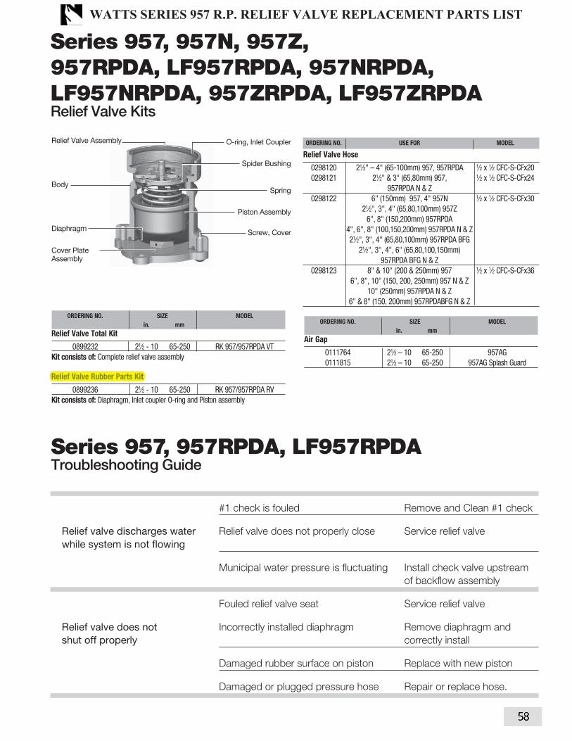
#1 check is fouled Remove and Clean #1 check
Relief valve discharges water Relief valve does not properly close Service relief valve
while system is not flowing
Municipal water pressure is fluctuating Install check valve upstream
of backflow assembly
Fouled relief valve seat Service relief valve
Relief valve does not Incorrectly installed diaphragm Remove diaphragm and
shut off properly correctly install
Damaged rubber surface on piston Replace with new piston
Damaged or plugged pressure hose Repair or replace hose.
7
Series 957, 957RPDA, LF957RPDA
ORDERING NO. SIZE MODEL
in. mm
Relief Valve Total Kit
0899232 21⁄2 - 10 65-250 RK 957/957RPDA VTKit consists of: Complete relief valve assembly Relief Valve Rubber Parts Kit
0899236 21⁄2 - 10 65-250 RK 957/957RPDA RVKit consists of: Diaphragm, Inlet coupler O-ring and Piston assembly
ORDERING NO. SIZE MODEL
in. mm
Air Gap
0111764 21⁄2 – 10 65-250 957AG 0111815 21⁄2 – 10 65-250 957AG Splash Guard
O-ring, Inlet Coupler
Spider Bushing
Spring
Piston Assembly
Screw, Cover
Relief Valve Assembly
Body
Diaphragm
Cover Plate Assembly
Series 957, 957N, 957Z, 957RPDA, LF957RPDA, 957NRPDA, LF957NRPDA, 957ZRPDA, LF957ZRPDA
ORDERING NO. USE FOR MODEL
Relief Valve Hose
0298120 21⁄2" – 4" (65-100mm) 957, 957RPDA 1⁄2 x 1⁄2 CFC-S-CFx20 0298121 21⁄2" & 3" (65,80mm) 957, 1⁄2 x 1⁄2 CFC-S-CFx24 957RPDA N & Z 0298122 6" (150mm) 957, 4" 957N 1⁄2 x 1⁄2 CFC-S-CFx30 21⁄2", 3", 4" (65,80,100mm) 957Z 6", 8" (150,200mm) 957RPDA 4", 6", 8" (100,150,200mm) 957RPDA N & Z 21⁄2", 3", 4" (65,80,100mm) 957RPDA BFG 21⁄2", 3", 4", 6" (65,80,100,150mm) 957RPDA BFG N & Z 0298123 8" & 10" (200 & 250mm) 957 1⁄2 x 1⁄2 CFC-S-CFx36 6", 8", 10" (150, 200, 250mm) 957 N & Z 10" (250mm) 957RPDA N & Z 6" & 8" (150, 200mm) 957RPDABFG N & Z
Relief Valve Rubber Parts Kit
WATTS SERIES 957 R.P. RELIEF VALVE REPLACEMENT PARTS LIST
58

MODEL 350 Double Check Backflow Preventers 3/4” & 1”
ITEM
NO.DESCRIPTION 3/4” 1”
1 BODY 352-1-010F 353-1-010F
2 HOUSING 352-1A 353-1A
3 #1 SEAT 352-18A 353-18A
4 #2 SEAT 352-18B 353-18B
5 O-RING #1 WK-125N 131N
6 O-RING #2 126N 132N
7 POPPET 352-30 353-30
8 SPRING 352-33 353-33
9 SLEEVE 352-2 353-2
10 O-RING, HOUSING INLET 214N 220N-80
11 O-RING, HOUSING OUTLET 223N 226N-80
12 SCREWS 352-11 352-11
13 TEST COCKS 18-860 18-860
14 BALL VALVE, INLET 34-850T 1-850T
15 BALL VALVE, OUTLET 34-850 1-850
16 CHECK ASSEMBLY #1 352-300A 353-300A
17 CHECK ASSEMBLY #2 352-300B 353-300B
18 HOUSING ASSEMBLY RK34-350V RK1-350V
19 TEST COCK CAP PLUG 2-7P 2-7P
RK34-350R REPAIR KIT, RUBBERMODEL 350 3/4”
RK1-350R REPAIR KIT, RUBBERMODEL 350, 1”
PART NO. QTY. DESCRIPTION PART NO. QTY. DESCRIPTION
WK-125N 1 O-RING #1 CHECK ASSY 131N 1 O-RING #1 CHECK ASSY
126N 1 O-RING #2 CHECK ASSY 132N 1 O-RING #2 CHECK ASSY
214N 1 O-RING, HOUSING INLET 220N-80 1 O-RING, HOUSING INLET
223N 1 O-RING, HOUSING OUTLET 226N-80 1 O-RING, HOUSING OUTLET
352-30 2 POPPET 353-30 2 POPPET
RK34-350 REPAIR KIT, COMPLETEMODEL 350, 3/4”
RK1-350 REPAIR KIT, COMPLETEMODEL 350, 1”
PART NO. QTY. DESCRIPTION PART NO. QTY. DESCRIPTION
352-300A 1 #1 CHECK ASSEMBLY 353-300A 1 #1 CHECK ASSEMBLY
352-300B 1 #2 CHECK ASSEMBLY 353-300B 1 #2 CHECK ASSEMBLY
214N 1 O-RING, HOUSING INLET 220N-80 1 O-RING, HOUSING INLET
223N 1 O-RING, HOUSING OUTLET 226N-80 1 O-RING, HOUSING OUTLET
RK34-350V REPAIR KIT, VESSELMODEL 350, 3/4”
RK1-350V REPAIR KIT, VESSELMODEL 350, 1”
PART NO. QTY. DESCRIPTION PART NO. QTY. DESCRIPTION
ITEM 18 1 HOUSING ASSEMBLY ITEM 18 1 HOUSING ASSEMBLY
REPAIR KITS
2
a company®
REPAIR KITS
WILKINS SERIES 350 D.C. .75" & 1" REPLACEMENT PARTS LIST
59

3
18
15
1
14
OUTLET
O-RING
BLOW-OUT
FLUSH HOUSING
INLET
O-RING
2
10
16
17
9
8
7
4
6
3
5
11
13
12
19
RK34-350BOF
RK1-350BOF
RK34-350BOF BLOW OUT/FLUSH FITTINGMODEL 350, 3/4”
RK1-350BOF BLOW OUT/FLUSH FITTINGMODEL 350, 1”
PART NO. QTY. DESCRIPTION PART NO. QTY. DESCRIPTION
352-1BOF 1 HOUSING, BLOW OUT/FLUSH, 3/4" 353-1BOF 1 HOUSING, BLOW OUT/FLUSH,1"
218N 1 O-RING, HOUSING INLET 223N-80 1 O-RING, HOUSING INLET
223N-80 1 O-RING, HOUSING OUTLET 226N-80 1 O-RING, HOUSING OUTLET
WILKINS SERIES 350 D.C. .75" & 1" REPLACEMENT PARTS LIST
60
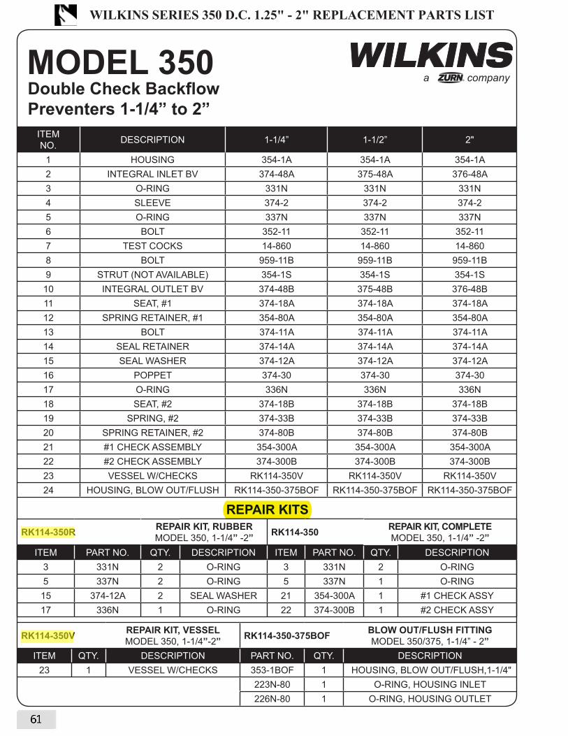
MODEL 350 Double Check Backflow Preventers 1-1/4” to 2”
a company®
ITEM
NO.DESCRIPTION 1-1/4” 1-1/2” 2"
1 HOUSING 354-1A 354-1A 354-1A
2 INTEGRAL INLET BV 374-48A 375-48A 376-48A
3 O-RING 331N 331N 331N
4 SLEEVE 374-2 374-2 374-2
5 O-RING 337N 337N 337N
6 BOLT 352-11 352-11 352-11
7 TEST COCKS 14-860 14-860 14-860
8 BOLT 959-11B 959-11B 959-11B
9 STRUT (NOT AVAILABLE) 354-1S 354-1S 354-1S
10 INTEGRAL OUTLET BV 374-48B 375-48B 376-48B
11 SEAT, #1 374-18A 374-18A 374-18A
12 SPRING RETAINER, #1 354-80A 354-80A 354-80A
13 BOLT 374-11A 374-11A 374-11A
14 SEAL RETAINER 374-14A 374-14A 374-14A
15 SEAL WASHER 374-12A 374-12A 374-12A
16 POPPET 374-30 374-30 374-30
17 O-RING 336N 336N 336N
18 SEAT, #2 374-18B 374-18B 374-18B
19 SPRING, #2 374-33B 374-33B 374-33B
20 SPRING RETAINER, #2 374-80B 374-80B 374-80B
21 #1 CHECK ASSEMBLY 354-300A 354-300A 354-300A
22 #2 CHECK ASSEMBLY 374-300B 374-300B 374-300B
23 VESSEL W/CHECKS RK114-350V RK114-350V RK114-350V
24 HOUSING, BLOW OUT/FLUSH RK114-350-375BOF RK114-350-375BOF RK114-350-375BOF
6
RK114-350R REPAIR KIT, RUBBERMODEL 350, 1-1/4” -2” RK114-350 REPAIR KIT, COMPLETE
MODEL 350, 1-1/4” -2”ITEM PART NO. QTY. DESCRIPTION ITEM PART NO. QTY. DESCRIPTION
3 331N 2 O-RING 3 331N 2 O-RING
5 337N 2 O-RING 5 337N 1 O-RING
15 374-12A 2 SEAL WASHER 21 354-300A 1 #1 CHECK ASSY
17 336N 1 O-RING 22 374-300B 1 #2 CHECK ASSY
REPAIR KITS
RK114-350V REPAIR KIT, VESSELMODEL 350, 1-1/4”-2” RK114-350-375BOF BLOW OUT/FLUSH FITTING
MODEL 350/375, 1-1/4” - 2”ITEM QTY. DESCRIPTION PART NO. QTY. DESCRIPTION
23 1 VESSEL W/CHECKS 353-1BOF 1 HOUSING, BLOW OUT/FLUSH,1-1/4"
223N-80 1 O-RING, HOUSING INLET
226N-80 1 O-RING, HOUSING OUTLET
REPAIR KITS
WILKINS SERIES 350 D.C. 1.25" - 2" REPLACEMENT PARTS LIST
61

7
5 11 13 14 15 16 19 12
21
2019161514131817
22
3 4 5
1
62 7
6
3
10
8
9
3
5
BLOW OUT
FLUSH HOUSING
RK114-350-375BOF
(FITS 1-1/4” - 2”)
(USE WITH ITEM # 4
BELOW)
3
24
23
WILKINS SERIES 350 D.C. 1.25" - 2" REPLACEMENT PARTS LIST
62

20
MODEL 350A & 350 Double Check Backflow Preventers (350A 2 1/2”-10”) (350 4”-12”)
a company®
ITEM
NO.DESCRIPTION 2 1/2” 3” 4” 6” 8” 10” 12”
1 GATE VALVE, NRS 212-48GXF 3-48GXF 4-48 6-48 8-48 10-48 12-48
GATE VALVE, OS&Y 212-48OSYGXF 3-48OSYGXF 4-48OSY 6-48OSY 8-48OSY 10-48OSY 12-48OSY
GATE VALVE, OS&Y (F&G) 212-48OSYGXF 3-48OSYGXF 4-48OSYGXF 6-48OSYGXF 8-48OSYGXF 10-48OSYGXF N/A
BUTTERFLY VALVE 212-49GVIC 3-49GVIC 4-49GVIC 6-49GVIC 8-49GVIC 10-49GVIC N/A
2 BOLT, FLANGE N/A N/A 559-11 5510-11 9511-11B 9512-11B 9512-11B
3 NUT, FLANGE N/A N/A 558-9 5510-9 5510-9 9512-9A 9512-9A
4 GASKET, FLANGE N/A N/A 559-13 5510-13 9511-13 9512-13 9512-13
5 O-RING, COVER PLATE 031N 031N 031N 031N 142N 142N 142N
6 COVER PLATE 558-3AXL-010F 558-3AXL-010F 558-3AXL-010F 558-3AXL-010F 3511-3AXL-010F 3511-3AXL-010F 3511-3AXL-010F
7 BOLT, COVER PLATE 554-11A 554-11A 554-11A 554-11A 957-11 957-11 957-11
8 SEAT RETAINER #2 3509-140 3509-140 3509-140 3510-140 3511-14DSS 3511-14DSS 3511-14DSS
9 SEAT RETAINER #1 3509-14B 3509-14B 3509-14B 3510-14B 3511-9 (NUT) 3511-9 (NUT) 3511-9 (NUT)
10 COVER 3509-3C 3509-3C 3509-3C 3510-3C 3511-3C 3511-3C 3511-3C
11 COVER RETAINER ASSY 6-23 6-23 6-23 8-23 12-23 12-23 12-23
12 BULKHEAD FITTING ASSY BHF1CXL-100 BHF1CXL-100 BHF1CXL-100 BHF2BXL-100 BHF2BXL-100 BHF2BXL-100 BHF2BXL-100
13 BALL VALVE 12-850XL 12-850XL 12-850XL 34-850XL 34-850XL 34-850XL 34-850XL
14 COUPLING 12-51 12-51 12-51 557-51 557-51 557-51 557-51
15 NIPPLE, LONG 558-21B 558-21B 558-21B 34X3-21B 34X3-21B 34X3-21B 34X3-21B
16 O-RING 353N 353N 353N 364N 273N 273N 273N
17 PLUG 558-7 558-7 558-7 5510-7 5510-7 5510-7 5510-7
18 BOLT, POPPET RETAINER 558-11E 558-11E 558-11E 5510-11A 3511-11 3511-11 3511-11
19 HANDLE, #1 POPPET ASSY 3509-6 3509-6 3509-6 3510-6 N/A N/A N/A
20 WASHER 3509-14C 3509-14C 3509-14C 3510-14C 3510-14C 3510-14C 3510-14C
21 O-RING 109N 109N 109N 204N 204N 204N 204N
22 POPPET RETAINER 3509-14 3509-14 3509-14 3510-14 3511-14 3511-14 3511-14
23 SEAL RING 3509-12 3509-12 3509-12 3510-12 3511-12 3511-12 3511-12
24 SEAT ASSEMBLY, #1 POPPET 3509-180 3509-180 3509-180 3510-180 3512-180A 3512-180A 3512-180A
25 SEAT ASSEMBLY, #2 POPPET 3509-180 3509-180 3509-180 3510-180 3512-180B 3512-180B 3512-180B
26 #1 CHECK ASSEMBLY 3509-300A 3509-300A 3509-300A 3510-300A 3512-300A 3512-300A 3512-300A
27 #2 CHECK ASSEMBLY 3509-300B 3509-300B 3509-300B 3510-300B 3512-300B 3512-300B 3512-300B
28 BULKHEAD FITTING ASSY BHF1BXL-100 BHF1BXL-100 BHF1BXL-100 BHF1BXL-100 BHF2CXL-100 BHF2CXL-100 BHF2C-100
29 PLUG 558-7 558-7 558-7 558-7 558-7 558-7 558-7
30 BALL VALVE 12-850MXL 12-850MXL 12-850MXL 34-850XL 34-850XL 34-850XL 34-850XL
31 NIPPLE, LONG N/A N/A N/A 5510-21B 5510-21B 5510-21B 5510-21B
32 LIFTING LUG N/A N/A N/A 9510-24 9510-24 N/A N/A
33 GASKET, COVER RETAINER 6-23-13 6-23-13 6-23-13 8-23-13 12-23-13 12-23-13 12-23-13
34 WASHER N/A N/A N/A N/A 3511-14E 3511-14E 3511-14E
35 BULKHEAD FITTING, GASKET BHF1-13 BHF1-13 BHF1-13 BHF1-13 BHF1-13 BHF1-13 BHF1-13
36 GROOVED COUPLING 4X212-23 4X3-23 4-23 6-23 8-23 10-23 N/A
37 GASKET N/A N/A 4-23-13 6-23-13 8-23-13 10-23-13 N/A
RK4-350REPAIR KIT
MODEL 350 4"
MODEL 350A, 2 1/2", 3", 4”RK6-350 REPAIR KIT
MODEL 350 & 350A, 6”RK8-350
REPAIR KITMODEL 350 8", 10", 12"
MODEL 350A, 8”, 10”
PART NO. QTY. DESCRIPTION PART NO. QTY. DESCRIPTION PART NO. QTY. DESCRIPTION
3509-12 2 SEAL RING 3510-12 2 SEAL RING 3511-12 2 SEAL RING
353N 2 O-RING 364N 2 O-RING 273N 2 O-RING
109N 8 O-RING 204N 8 O-RING 204N 12 O-RING
REPAIR KITSREPAIR KITS
WILKINS SERIES 350A & 350 D.C. REPLACEMENT PARTS LIST
63

21
18
21
23
24
26
11
12
10
9
8
13
12
30
31
14
13
1
17
12
28
29
5
6
7
33
13
#1 CHECK ASSEMBLY
(350 4" & 6")
MODEL 350A
(2 1/2" - 10")
19
1535
35
#2 CHECK ASSEMBLY
(350 8” - 12”)
(350A 8" & 10")
27
8
25
34
16
3 4
2
32
22
20
25
16
27
#2 CHECK ASSEMBLY
(350 4" & 6")
(350A 2 1/2” -6”)
9
23
22
32
MODEL 350 (4"-12")
36
37
(350A 2 1/2” & 6")
#1 CHECK ASSEMBLY
(350 8” - 12”)
(350A 8" & 10")
23
22 18
20 21
26
24
9
34
WILKINS SERIES 350A & 350 D.C. REPLACEMENT PARTS LIST
64

MODEL 950XL
Double Check Backflow
Preventers 3/4” to 2”
RK34-950XL REPAIR KIT, RUBBER & SPRINGMODEL 950XL, 3/4” & 1” Only
RK114-950XL REPAIR KIT, RUBBER & SPRINGMODEL 950XL, 1-1/4”, 1-1/2”, 2” Only
PART NO. QTY. DESCRIPTION PART NO. QTY. DESCRIPTION
952-12S 2 SEAL RING 954-12S 2 SEAL RING
136N 2 O-RING, COVER 153N 2 O-RING, COVER
952-33 2 CHECK SPRING 554-33 2 CHECK SPRING
ITEM
NO.DESCRIPTION 3/4” 1” 1-1/4” 1-1/2” 2”
1 CHECK COVER 952-3-010F 952-3-010F 954-3-010F 954-3-010F 954-3-010F
2 O-RING, COVER 136N 136N 153N 153N 153N
3 CHECK SPRING 952-33 952-33 554-33 554-33 554-33
4 POPPET 952-30-010F 952-30-010F 954-30-010F 954-30-010F 954-30-010F
5 SEAL RING 952-12S 952-12S 954-12S 954-12S 954-12S
6 SEAL RING RETAINER 952-14 952-14 954-14 954-14 954-14
7 RETAINING BOLT 952-11 952-11 952-11 952-11 952-11
8 CHECK SEAT 952-18S 952-18S 954-18S 954-18S 954-18S
9 O-RING, CHECK SEAT WK-125N WK-125N 136N 136N 136N
10 TEST COCK 18-860 18-860 14-860 14-860 14-860
11 BALL VALVE, TAPPED 34-850T 1-850T 114-850T 112-850T 2-850T
12 BALL VALVE 34-850 1-850 114-850 112-850 2-850
13 POPPET ASSEMBLY 952-300S 952-300S 954-300S 954-300S 954-300S
CHECK SEAT TOOL 972-SEATTOOL 974-SEATTOOL
a company®
REPAIR KITS
RK34-950XLR REPAIR KIT, RUBBERMODEL 950XL, 3/4” & 1” Only
RK114-950XLRREPAIR KIT, RUBBER
MODEL 950XL, 1-1/4”, 1-1/2”, 2”
Only
PART NO. QTY. DESCRIPTION PART NO. QTY. DESCRIPTION
952-12S 2 SEAL RING 954-12S 2 SEAL RING
136N 2 O-RING, COVER 153N 2 O-RING, COVER
10
RK34-950XLC REPAIR KIT, COMPLETEMODEL 950XL, 3/4” & 1” Only
RK114-950XLC REPAIR KIT, COMPLETEMODEL 950XL, 1-1/4”, 1-1/2”, 2” Only
PART NO. QTY. DESCRIPTION PART NO. QTY. DESCRIPTION
952-300 2 POPPET ASSY, 3/4" XL 954-300S 2 POPPET ASSY, 1-1/4" XL
952-18S 2 CHECK SEAT 954-18S 2 CHECK SEAT
136N 2 O-RING, COVER 153N 2 O-RING, COVER
WK-125N 2 O-RING, CHECK SEAT 136N 2 O-RING, CHECK SEAT
952-33 2 CHECK SPRING 554-33 2 CHECK SPRING
RK34-950XLSK REPAIR KIT, SEATSMODEL 950XL, 3/4” & 1” Only
RK114-950XLSK REPAIR KIT, SEATSMODEL 950XL, 1-1/4”, 1-1/2”, 2” Only
PART NO. QTY. DESCRIPTION PART NO. QTY. DESCRIPTION
952-18S 2 CHECK SEAT 954-18S 2 CHECK SEAT
WK-125N 2 O-RING, COVER 136N 2 O-RING, CHECK SEAT
REPAIR KITS
WILKINS SERIES 950XL D.C. REPLACEMENT PARTS LIST
65

11
1
2
3
4
5
7
86
9
10
12
13
11
WILKINS SERIES 950XL D.C. REPLACEMENT PARTS LIST
66

28
MODEL 950 Double Check Backflow Preventers 2-1/2” to 10”
a company®
ITEM
NO. DESCRIPTION 2-1/2” 3” 4” 6” 8” 10”
1 GATE VALVE, NRS 212-48 3-48 4-48 6-48 8-48 10-48
GATE VALVE, OS&Y 212-48OSY 3-48OSY 4-48OSY 6-48OSY 8-48OSY 10-48OSY
2 BOLT, FLANGE 558-11D 558-11D 559-11 5510-11 9511-11B 9512-11B
3 NUT, FLANGE 558-9 558-9 558-9 5510-9 5510-9 9512-9A
4 GASKET, FLANGE 557-13 558-13 559-13 5510-13 9511-13 9512-13
5 STUD, FLANGE 959-11A 959-11A 959-11A 9511-11A 9511-11A N/A
6 O-RING, SMALL 022N 022N 022N 022N 022N 022N
7 O-RING, LARGE 033N 033N 033N 033N 036N 036N
8 COVER PLATE 957-3A-010F 957-3A-010F 957-3A-010F 957-3A-010F 9511-3A-010F 9511-3A-010F
9 BOLT, COVER PLATE 554-11A 554-11A 554-11A 554-11A 554-11A 554-11A
10 COVER 957-3C 957-3C 959-3C 9510-3C 9511-3C 9512-3C
11 O-RING, COVER 248N 248N 264N 374N 452N 457N
12 BOLT, COVER 957-11 957-11 959-11 9510-11 9511-11 9512-11
13 NIPPLE, SHORT N/A N/A N/A 102-21B 102-21B 102-21B
14 BALL VALVE, MALE 12-850M 12-850M 12-850M N/A N/A N/A
BALL VALVE, FEMALE 12-850 12-850 12-850 34-850XL 34-850XL 34-850XL
15 O-RING, SEAT 238N 238N 252N 366N 374N 379N
16 SEAT 957-18-010F 957-18-010F 959-18-010F 9510-18-010F 9511-18-010F 9512-18-010F
17 BOLT, SEAT 5752-11 5752-11 959-11B 959-11B 959-11B 959-11B
18 LOWER STEM GUIDE N/A N/A 959-2 957-2 9511-2 9512-2
19 NUT, STEM 957-9 957-9 959-9 9511-9 9511-9 9512-9
20 RETAINING PLATE 957-31-010F 957-31-010F 959-14-010F 9510-14-010F 9511-14-010F 9512-14-010F
21 SEAL RING 558-12 558-12 959-12 9510-12 9511-12 9512-12
22 POPPET ASSEMBLY 957-300 957-300 959-300 9510-300 9511-300 9512-300
23 UPPER STEM GUIDE 957-2 957-2 957-2 9510-2 9511-2A 9512-2A
24 NIPPLE, LONG 558-21B 558-21B 558-21B 5510-21B 5510-21B 5510-21B
25 PLUG 558-7 558-7 558-7 5510-7 5510-7 5510-7
26 LIFTING LUG N/A N/A N/A 9510-24 9510-24 N/A
RK4-950 REPAIR KITMODELS 950/975, 4”
RK8-950 REPAIR KITMODELS 950/975, 8”
PART NO. QTY. DESCRIPTION PART NO. QTY. DESCRIPTION
959-12 2 SEAL RING 9511-12 2 SEAL RING
264N 2 O-RING, COVER 452N 2 O-RING, COVER
REPAIR KITS
RK212-950REPAIR KIT
MODELS 950/975
2-1/2” & 3”
RK6-950 REPAIR KITMODELS 950/975, 6”
RK10-950 REPAIR KITMODELS 950/975, 10”
PART NO. QTY. DESCRIPTION PART NO. QTY. DESCRIPTION PART NO. QTY. DESCRIPTION
558-12 2 SEAL RING 9510-12 2 SEAL RING 9512-12 2 SEAL RING
248N 2 O-RING, COVER 374N 2 O-RING, COVER 457N 2 O-RING, COVER
REPAIR KITS
WILKINS SERIES 950 D.C. REPLACEMENT PARTS LIST
67

29
121413
14
2
1
3
4
5
9
8
76
10
CHECK ASSY
(4"-10") SHOWN
CHECK ASSY
(21⁄2" - 3") SHOWN
11
15
18 17
15
16
17
19
21
16
20
20
22
22
24
14
23
23
25
26
26
WILKINS SERIES 950 D.C. REPLACEMENT PARTS LIST
68

MODEL 375 Reduced Pressure Principle Backflow Preventers 3/4” to 1”
a company®
ITEM
NO.DESCRIPTION 3/4” 1”
1 WEDGE SCREW 372-11B 373-11B
2 WEDGE 372-23 373-23
3 O-RING, SLEEVE 118N 216N
4 SLEEVE 372-2 373-2
5 O-RING, #1 CHECK SEAT 124N 225N
6 #1 CHECK SEAT 372-18A 373-18A
7 POPPET SCREW 30-11 952-11
8 CHECK SEAL RETAINER 372-14A 373-14A
9 CHECK SEAL RING 372-12A 373-12A
10 POPPET 372-30 373-30
11 #1 CHECK SPRING 372-33A 373-33A
12 #1CHECK SPRING RETAINER 372A-80A 373A-80A
13 O-RING, #2 CHECK SEAT 124N 223N
14 #2 CHECK SEAT 372-18B 373-18B
15 #2 CHECK SPRING 372-33B 373-33B
16 #2 CHECK SPRING RETAINER 372A-80B 373A-80B
17 O-RING, HOUSING INLET 130N 227N
18 TEST COCK 18-860 18-860
19 CHECK HOUSING 372-1 373-1
20 O-RING, HOUSING OUTLET 119N 218N
21 O-RING, RV COVER 010N 010N
22 O-RING, RV SEAT 018N 018N
23 RELIEF VALVE SEAT 372-18 372-18
24 RELIEF VALVE SPRING 372-33CU 372-33CU
25 RV SEAL RETAINING SCREW 372-11C 372-11C
26 RV SEAL RING 372-12 372-12
27 RV LOWER PLUNGER 372-34A 372-34A
28 DIAPHRAGM 372-43 372-43
29 RV UPPER PLUNGER 372-34 372-34
30 O-RING, RV STEM 015N 015N
31 RELIEF VALVE COVER 372-3 373-3
32 RV COVER SCREW, SHORT 372-11B 372-11B
RV COVER SCREW, LONG 372-11
33 INLET BALL VALVE 372-48A 373-48A
34 OUTLET BALL VALVE 372-48B 373-48B
35 #1 CHECK ASSEMBLY 372-300A 373-300A
36 #2 CHECK ASSEMBLY 372-300B 373-300B
37 RELIEF VALVE STEM ASSY 372-50 372-50
38 COMPLETE VESSEL ASSY RK34-375V RK1-375V
39 HOUSING, BLOW OUT/FLUSH 372-1BOF 373-1BOF
REPAIR KIT COMPLETE RK34-3753/4” 375
RK1-3751” 375
DESCRIPTION PART NO. QTY. PART NO. QTY.
#1 CHECK ASSEMBLY 372-300A 1 373-300A 1
#2 CHECK ASSEMBLY 372-300B 1 373-300B 1
RELIEF VALVE STEM ASSY 372-50 1 372-50 1
O-RING, SLEEVE 118N 1 216N 1
O-RING, HOUSING INLET 130N 1 227N 1
O-RING, HOUSING OUTLET 119N 1 218N 1
O-RING, RV COVER 010N 1 010N 1
O-RING, RV SEAT 018N 1 018N 1
RELIEF VALVE SEAT 372-18 1 372-18 1
RELIEF VALVE SPRING 372-33CU 1 372-33CU 1
REPAIR KIT, RUBBER ONLY RK34-375R3/4” 375
RK1-375R1” 375
DESCRIPTION PART NO. QTY. PART NO. QTY.
O-RING, #1 CHECK SEAT 124N 1 225N 1
O-RING, #2 CHECK SEAT 124N 1 223N 1
CHECK SEAL RING 372-12A 2 373-12A 2
O-RING, SLEEVE 118N 1 216N 1
O-RING, HOUSING INLET 130N 1 227N 1
O-RING, HOUSING OUTLET 119N 1 218N 1
O-RING, RV COVER 010N 1 010N 1
O-RING, RV SEAT 018N 1 018N 1
RELIEF VALVE SEAL RING 372-12 1 372-12 1
DIAPHRAGM 372-43 1 372-43 1
O-RING, RV STEM 015N 1 015N 1
REPAIR KIT, VESSEL ASSY RK34-375V3/4” 375
RK1-375V1” 375
DESCRIPTION PART NO. QTY. PART NO. QTY.
VESSEL W/CHECKS AND RV ITEM 38 1 ITEM 38 1
REPAIR KIT, WEDGE ASSY RK34-375W3/4” 375
RK1-375W1” 375
DESCRIPTION PART NO. QTY. PART NO. QTY.
O-RING, SLEEVE 118N 1 216N 1
SLEEVE 372-2 1 373-2 1
WEDGE 372-23 1 373-23 1
WEDGE SCREW 372-11B 2 373-11B 2
BLOW OUT/FLUSH FITTING RK34-375BOF3/4” 375
RK1-375BOF1” 375
DESCRIPTION PART NO. QTY. PART NO. QTY.
HOUSING, BLOW OUT/FLUSH 372-1BOF 1 373-1BOF 1
O-RING, HOUSING INLET 130N 1 227N 1
O-RING, HOUSING OUTLET 119N 1 218N 1
38
REPAIR KITSREPAIR KITS
WILKINS SERIES 375 R.P. REPLACEMENT PARTS LIST
69

39
OUTLET
O-RING
RK34-375BOF
RK1-375BOF
INLET
O-RING
BLOW-OUT
FLUSH HOUSING
2
38
18
19
12
21
2217
20
1
11
9
10
85 6
7
15
36
13 14
4
3
35
16
25
27
26
28
29
30
24
34
37
31
32
33
23
39
WILKINS SERIES 375 R.P. REPLACEMENT PARTS LIST
70

MODEL 375
Reduced Pressure Principle Backflow Preventers 1-1/4” to 2”
a company®
ITEM
NO.DESCRIPTION 1-1/4” 1-1/2” 2”
1 HOUSING 374-1 374-1 374-1
2 INTEGRAL INLET BV 374-48A 375-48A 376-48A
3 O-RING 331N 331N 331N
4 SLEEVE 374-2 374-2 374-2
5 O-RING 337N 337N 337N
6 BOLT 352-11 352-11 352-11
7 TEST COCKS 14-860 14-860 14-860
8 BOLT 959-11B 959-11B 959-11B
9 STRUT (NOT AVAILABLE) 374-1S 374-1S 374-1S
10 INTEGRAL OUTLET BV 374-48B 375-48B 376-48B
11 SEAT, #1 374-18A 374-18A 374-18A
12 SPRING, #1 374-33A 374-33A 374-33A
13 SPRING RETAINER, #1 374-80A 374-80A 374-80A
14 BOLT 374-11A 374-11A 374-11A
15 SEAL RETAINER 374-14A 374-14A 374-14A
16 SEAL WASHER 374-12A 374-12A 374-12A
17 POPPET 374-30 374-30 374-30
18 O-RING 336N 336N 336N
19 SEAT, #2 374-18B 374-18B 374-18B
20 SPRING, #2 374-33B 374-33B 374-33B
21 SPRING RETAINER, #2 374-80B 374-80B 374-80B
22 SEAL WASHER 374-12 374-12 374-12
23 SEAL RETAINER 374-14CU 374-14CU 374-14CU
24 BOLT 952-11 952-11 952-11
25 O-RING 334N 334N 334N
26 NUT 5752-9 5752-9 5752-9
27 O-RING 109N 109N 109N
28 BODY, RV 374-1CU 374-1CU 374-1CU
29 SEAT, RV 374-18CU 374-18CU 374-18CU
30 SPRING GUIDE 374-80CU 374-80CU 374-80CU
31 SPRING, RV 374-33CU 374-33CU 374-33CU
32 DIAPHRAGM 374-43 374-43 374-43
33 PLUNGER, RV 374-34 374-34 374-34
34 O-RING 123N 123N 123N
35 O-RING 243N 243N 243N
36 COVER 374-3 374-3 374-3
37 BOLT 374-11 374-11 374-11
38 SPACER 374-2A 374-2A –
39 #1 CHECK ASSY 374-300A 374-300A 374-300A
40 #2 CHECK ASSY 374-300B 374-300B 374-300B
41 RELIEF VALVE STEM ASSY 374-50 374-50 374-50
42 VESSEL W/CHECKS & RV RK114-375V RK114-375V RK114-375V
43 HOUSING, BLOW OUT/FLUSH RK114-350-375BOF RK114-350-375BOF RK114-350-375BOF
42
WILKINS SERIES 375 R.P. REPLACEMENT PARTS LIST
71

RK114-375R REPAIR KITMODEL 375, 1-1/4” - 2”
RK114-375 REPAIR KITMODEL 375, 1-1/4” -2”
RK114-375V REPAIR KITMODEL 375, 1-1/4” -2”
ITEM PART NO. QTY. DESCRIPTION ITEM PART NO. QTY. DESCRIPTION ITEM QTY. DESCRIPTION
3 331N 2 O-RING 3 331N 2 O-RING 42 1 VESSEL W/CHECKS & RV
5 337N 2 O-RING 5 337N 1 O-RING
16 374-12A 2 SEAL WASHER 39 374-300A 1 #1 CHECK ASSY
18 336N 1 O-RING 40 374-300B 1 #2 CHECK ASSY
22 374-12 1 SEAL WASHER 22 374-12 1 SEAL WASHER
25 334N 1 O-RING 23 374-14CU 1 SEAL RETAINER
27 109N 2 O-RING 25 334N 1 O-RING
32 374-43 1 DIAPHRAGM 27 109N 2 O-RING
34 123N 1 O-RING 35 243N 1 O-RING
35 243N 1 O-RING 41 374-50 1 RELIEF VLV. STEM ASSY
43
37
29
30
31
28
32
33
34
35
36
26
37
27
25
22
24
23
27
610
3
8
1
2
7
34
5
18 19 14 15 16 17 2021
5 11 14 15 16 1712
1338
9
42
40
39
41
WILKINS
375 RP
6
3
5 RK114-350-375BOF
(FITS 1-1/4” - 2”)
(USE WITH ITEM # 4
BELOW)
3
43
BLOW OUT
FLUSH HOUSING
REPAIR KITS
BLOW OUT/ FLUSH FITTINGRK114-350-375BOF
MODEL 375, 1-1/4” -2”
ITEM QTY. DESCRIPTION
1 1 BODY, BLOW OUT FLUSH
3 2 O-RING
5 1 O-RING
REPAIR KITS
WILKINS SERIES 375 R.P. REPLACEMENT PARTS LIST
72

50
MODEL 375A & 375 Reduced Pressure Principle Backflow Preventers (375A 2 1/2”-10”) (375 4”-10”)
a company®
ITEM NO. DESCRIPTION 2 1/2" 3" 4” 6” 8” 10”
1 GATE VALVE, NRS 212-48GXF 3-48GXF 4-48 6-48 8-48 10-48
GATE VALVE, OS&Y 212-48OSYGXF 3-48OSYGXF 4-48OSY 6-48OSY 8-48OSY 10-48OSY
GATE VALVE, OS&Y (F&G) 212-48OSYGXF 3-48OSYGXF 4-48OSYGXF 6-48OSYGXF 8-48OSYGXF 10-48OSYGXF
BUTTERFLY VALVE 212-49GVIC 3-49GVIC 4-49GVIC 6-49GVIC 8-49GVIC 10-49GVIC
2 BOLT, FLANGE N/A N/A 559-11 5510-11 9511-11B 9512-11B
3 NUT, FLANGE N/A N/A 558-9 5510-9 5510-9 9512-9A
4 GASKET, FLANGE N/A N/A 559-13 5510-13 9511-13 9512-13
5 O-RING, CONTROL UNIT 032N 032N 032N 032N 142N 142N
6 RELIEF VALVE ASSY 3707-CU-XL 3707-CU-XL 3707-CU-XL 3707-CU-XL 3711-CU-XL 3711-CU-XL
7 BOLT, RELIEF VALVE 554-11A 554-11A 554-11A 554-11A 957-11 957-11
8 SEAT RETAINER #2 3509-140 3509-140 3509-140 3510-140 3511-14DSS 3511-14DSS
9 SEAT RETAINER #1 3509-14B 3509-14B 3509-14B 3510-14B 3511-9 (NUT) 3511-9 (NUT)
10 COVER 3509-3C 3509-3C 3509-3C 3510-3C 3511-3C 3511-3C
11 COVER RETAINER ASSY 6-23 6-23 6-23 8-23 12-23 12-23
12 BULKHEAD FITTING ASSY BHF1CXL-100 BHF1CXL-100 BHF1CXL-100 BHF2BXL-100 BHF2BXL-100 BHF2BXL-100
13 BALL VALVE 12-850XL 12-850XL 12-850XL 34-850XL 34-850XL 34-850XL
14 COUPLING 12-51 12-51 12-51 557-51 557-51 557-51
15 NIPPLE, LONG 558-21B 558-21B 558-21B 34X3-21B 34X3-21B 34X3-21B
16 PLUG 558-7 558-7 558-7 5510-7 5510-7 5510-7
17 O-RING 353N 353N 353N 364N 273N 273N
18 BOLT, POPPET RETAINER 558-11E 558-11E 558-11E 5510-11A 3511-11 3511-11
19 HANDLE, #1 POPPET ASSY 3509-6 3509-6 3509-6 3510-6 N/A N/A
20 WASHER 3509-14C 3509-14C 3509-14C 3510-14C 3510-14C 3510-14C
21 O-RING 109N 109N 109N 204N 204N 204N
22 POPPET RETAINER 3509-14 3509-14 3509-14 3510-14 3511-14 3511-14
23 SEAL RING 3509-12 3509-12 3509-12 3510-12 3511-12 3511-12
24 SEAT ASSEMBLY, #1 POPPET 3709-180 3709-180 3709-180 3710-180 3712-180 3712-180
25 SEAT ASSEMBLY, #2 POPPET 3509-180 3509-180 3509-180 3510-180 3512-180B 3512-180B
26 #1 CHECK ASSEMBLY 3709-300 3709-300 3709-300 3710-300 3712-300 3712-300
27 #2 CHECK ASSEMBLY 3509-300B 3509-300B 3509-300B 3510-300B 3512-300B 3512-300B
28 BULKHEAD FITTING ASSY BHF1BXL-100 BHF1BXL-100 BHF1BXL-100 BHF1BXL-100 BHF2CXL-100 BHF2CXL-100
29 SENSING TUBE FITTING 5758A-36 5758A-36 5758A-36 5758A-36 5758A-36 5758A-36
30 PITOT TUBE ASSY 3709-360 3709-360 3709-360 3709-360 3711-360 3711-360
31 SENSING TUBE 3709-36 3709-36 3709-36 3710-36 4710-36 4710-36
32 BALL VALVE 12-850MXL 12-850MXL 12-850MXL 34-850XL 34-850XL 34-850XL
33 BULKHEAD FITTING, GASKET BHF1-13 BHF1-13 BHF1-13 BHF1-13 BHF1-13 BHF1-13
34 LIFTING LUG N/A N/A N/A 9510-24 9510-24 N/A
35 GASKET, COVER RETAINER 6-23-13 6-23-13 6-23-13 8-23-13 12-23-13 12-23-13
36 WASHER N/A N/A N/A N/A 3511-14E 3511-14E
37 NIPPLE, LONG N/A N/A N/A 5510-21B 5510-21B 5510-21B
38 GROOVED COUPLING 4X212-23 4X3-23 4-23 6-23 8-23 10-23
39 COUPLING GASKET N/A N/A 4-23-13 6-23-13 8-23-13 10-23-13
RK4-350REPAIR KIT
MODEL 375, 4"
MODEL 375A, 2 1/2"-4"RK6-350 REPAIR KIT
MODEL 375 & 375A, 6”RK8-350
REPAIR KITMODEL 375, & 375A,
8”-10”
PART NO. QTY. DESCRIPTION PART NO. QTY. DESCRIPTION PART NO. QTY. DESCRIPTION
3509-12 2 SEAL RING 3510-12 2 SEAL RING 3511-12 2 SEAL RING
353N 2 O-RING 364N 2 O-RING 273N 2 O-RING
109N 8 O-RING 204N 8 O-RING 204N 12 O-RING
REPAIR KITSREPAIR KITS
WILKINS SERIES 375A & 375 R.P. REPLACEMENT PARTS LIST
73

51
22
20
25
17
18
21
23
24
2611
12
10
9
8
13
12
32
37
14
13
12
28
35
13
#1 CHECK ASSEMBLY (375 4” & 6” ) (375 & 375A 4" & 6")
#2 CHECK ASSEMBLY (375 4" & 6") (375A 2 1/2” - 6”)
MODEL 375A (2 1/2"- 10")
19
15
33
33
8
22
9
36
6
7
29
31
30
3 4
2
1
16
39
38
5
25
17
23
34
34
MODEL 375 (4"- 10")
26
#1 CHECK ASSEMBLY (375 & 375A 8" & 10")
24
23
22 18
20 21
9
36
17
27
27
#2 CHECK ASSEMBLY (375 & 375A 8" & 10")
WILKINS SERIES 375A & 375 R.P. REPLACEMENT PARTS LIST
74

MODEL 375, 375A, 475 & 475V 375XL, 375AXL, 475XL & 475XLVRelief Valve 2-1/2” to 10”
4
1
3
5
67
8
9
1011
2
13
14
12
RELIEF VALVE COMPLETE 3707-CU-XL 3711-CU-XL
ITEM
NO.DESCRIPTION QTY. 2-1/2”-6” QTY. 8” & 10”
1 BOLT, COVER 6 554-11A 8 957-11
2 O-RING 1 222N 1 227N
3 UPPER PLUNGER 1 3707-34 1 3711-34
4 DIAPHRAGM 1 3707-43 1 3711-43
5 LOWER PLUNGER 1 3707-34A 1 3711-34A
6 SEAL RING 1 3707-12 1 3711-12
7 SEAL RETAINER 1 3707-14 1 3711-14
8 SCREW 1 558-11E 1 558-11E
9 CU SPRING 1 3707-33A 1 3711A-33
10 CU SEAT 1 3707-18 1 3711-18
11 O-RING 1 032N 1 146N
12 WASHER 1 N/A 1 3707-14
13 STEM ASSY. 1 3707-50 1 3711-50
14 O-RING 1 032N 1 142N
a company®
REPAIR KITS, RUBBERRK212-375R
2-1/2”- 6”
RK8-375R
8” & 10”
ITEM
NO.DESCRIPTION QTY. PART NO. PART NO.
6 SEAL RING 1 3707-12 3711-12
4 DIAPHRAGM 1 3707-43 3711-43
2 O-RING 1 222N 227N
11 O-RING 1 032N 146N
14 O-RING 1 032N 142N
REPAIR KITS
REPAIR KITS, COMPLETERK212-375
2-1/2”- 6”
RK8-375
8” & 10”
ITEM
NO.DESCRIPTION QTY. PART NO. PART NO.
N/A REPAIR KIT, RUBBER 1 RK212-375R RK8-375R
9 SPRING 1 3707-33A 3711A-33
64
REPAIR KITS
WILKINS SERIES 375A & 375 R.P. REPLACEMENT PARTS LIST
75

34
MODEL 975XL Reduced Pressure Principle
Backflow Preventers 3/4” to 2” a company®
ITEM NO. DESCRIPTION 3/4” 1” 1-1/4” 1-1/2” 2”
1 BALL VALVE, TAPPED 34-850T 1-850T 114-850T 112-850T 2-850T
2 BALL VALVE 34-850 1-850 114-850 112-850 2-850
BFLY VALVE* N/A N/A 114-49BR 112-49BR 2-49BR
BFLY VALVE, TAPPED* N/A N/A 114-48BRT 112-BRT 2-49BRT
3 O-RING, CHECK SEAT WK-125N WK-125N 136N 136N 136N
4 CHECK SEAT 952-18S 952-18S 954-18S 954-18S 954-18S
5 RETAINING BOLT 952-11 952-11 952-11 952-11 952-11
6 SEAL RING RETAINER 952-14 952-14 954-14 954-14 954-14
7 SEAL RING 952-12S 952-12S 954-12S 954-12S 954-12S
8 POPPET 952-30-010F 952-30-010F 954-30-010F 954-30-010F 954-30-010F
9 NO.1 CHECK SPRING 972-33 972-33 5754-33 5754-33 5754-33
10 O-RING, COVER 136N 136N 153N 153N 153N
11 CHECK COVER 952-3-010F 952-3-010F 954-3-010F 954-3-010F 954-3-010F
12 POPPET ASSY. 952-300S 952-300S 954-300S 954-300S 954-300S
13 NO.2 CHECK SPRING 952-33 952-33 554-33 554-33 554-33
14 TEST COCK 18-860 18-860 14-860 14-860 14-860
15 O-RING, RELIEF VALVE SEAT WK-019N WK-019N 029N 029N 029N
16 RELIEF VALVE SEAT 972-18 972-18 974-18 974-18 974-18
17 RELIEF VALVE SPRING 972A-33 972A-33 974A-33 974A-33 974A-33
18 RELIEF VALVE RETAINING BOLT 972-11A 972-11A 604B-11 604B-11 604B-11
19 RELIEF VALVE SEAL RING RETAINER 972-14 972-14 552-14 552-14 552-14
20 RELIEF VALVE SEAL RING 972-12S 972-12S 974-12S 974-12S 974-12S
21 RELIEF VALVE LOWER PLUNGER 972-34A 972-34A 974-34A 974-34A 974-34A
22 RELIEF VALVE DIAPHRAGM 972-43 972-43 974-43 974-43 974-43
23 RELIEF VALVE UPPER PLUNGER 972-34 972-34 974-34 974-34 974-34
24 O-RING, RELIEF VALVE STEM WK-111N WK-111N 121N 121N 121N
25 RELIEF VALVE STEM ASSY. 972-50S 972-50S 974-50S 974-50S 974-50S
26 RELIEF VALVE COVER BOLT 554-11A 554-11A 554-11A 554-11A 554-11A
RV. & CHECK SEAT TOOL 972-SEATTOOL 974-SEATTOOL
27 RELIEF VALVE COVER 972-3A-010F 972-3A-010F 974-3A-010F 974-3A-010F 974-3A-010F
*INTEGRAL SUPERVISORY SWITCH OPTION AVAILABLE
RK34-975XLR RUBBER REPAIR KITMODEL 975XL, 3/4”, & 1” Only
RK114-975XLR RUBBER REPAIR KITMODEL 975XL, 1-1/4”, 1-1/2”, 2” Only
PART NO. QTY. DESCRIPTION PART NO. QTY. DESCRIPTION
952-12S 2 SEAL RING 954-12S 2 SEAL RING
972-12S 1 RELIEF VALVE SEAL RING 974-12S 1 RELIEF VALVE SEAL RING
972-43 1 DIAPHRAGM 974-43 1 DIAPHRAGM
136N 2 O-RING, COVER 153N 2 O-RING, COVER
WK-111N 1 O-RING, RELIEF VALVE STEM 121N 1 O-RING, RELIEF VALVE STEM
REPAIR KITSRK34-975XL REPAIR KIT COMPLETE
MODEL 975XL, 3/4”, & 1” OnlyRK114-975XL REPAIR KIT COMPLETE
MODEL 975XL, 1-1/4”,1-1/2”, 2” Only
PART NO. QTY. DESCRIPTION PART NO. QTY. DESCRIPTION
952-12S 2 SEAL RING 954-12S 2 SEAL RING
972-12S 1 RELIEF VALVE SEAL RING 974-12S 1 RELIEF VALVE SEAL RING
972-43 1 DIAPHRAGM 974-43 1 DIAPHRAGM
136N 2 O-RING, COVER 153N 2 O-RING, COVER
WK-111N 1 O-RING, RELIEF VALVE STEM 121N 1 O-RING, RELIEF VALVE STEM
972-33 1 NO. 1 CHECK SPRING 5754-33 1 NO. 1 CHECK SPRING
952-33 1 NO.2 CHECK SPRING 554-33 1 NO. 2 CHECK SPRING
972A-33 1 RELIEF VALVE SPRING 974A-33 1 RELIEF VALVE SPRING
REPAIR KITS
WILKINS SERIES 975XL R.P. REPLACEMENT PARTS LIST
76

35
11
10
9
8
7 6
5
4
3
14
15
16
17
25
22
21
19
18
20
1
12
13
2
23
24
26
27
RK34-975XLSK SEAT REPAIR KITMODEL 975XL, 3/4” & 1” Only
RK114-975XLSK SEAT REPAIR KITMODEL 975XL, 1-1/4”, 1-1/2”, 2” Only
PART NO. QTY. DESCRIPTION PART NO. QTY. DESCRIPTION
952-18S 2 CHK SEAT, 3/4" XL 954-18S 2 CHK SEAT, 1-1/4" XL
WK-125N 2 O-RING 136N 2 O-RING
972-18 1 CU SEAT, 3/4" XL 974-18 1 CU SEAT, 1-1/4" 975XL
WK-019N 1 O-RING, COVER 029N 1 O-RING, COVER
RK34-975XLSK RK114-975XLSK
WILKINS SERIES 975XL R.P. REPLACEMENT PARTS LIST
77
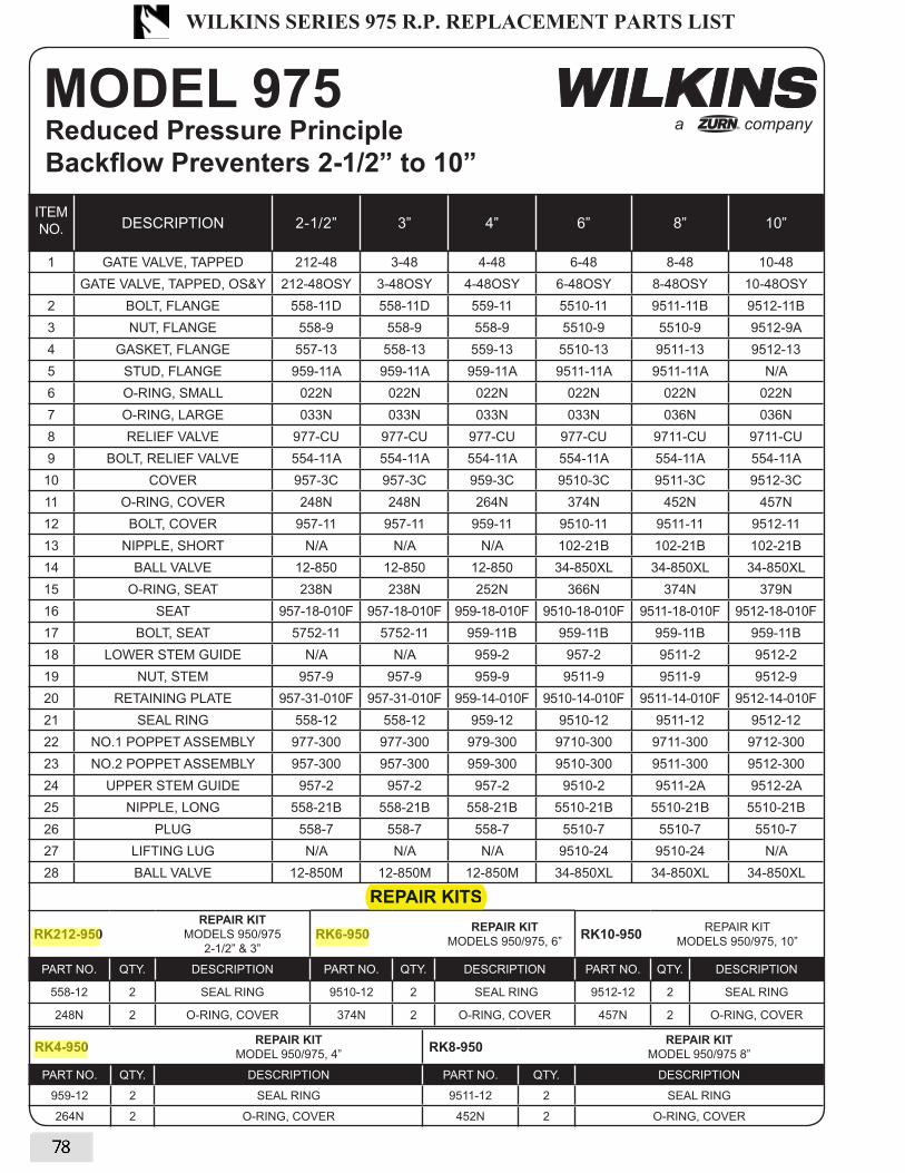
MODEL 975 Reduced Pressure Principle Backflow Preventers 2-1/2” to 10”
RK4-950 REPAIR KITMODEL 950/975, 4”
RK8-950 REPAIR KITMODEL 950/975 8”
PART NO. QTY. DESCRIPTION PART NO. QTY. DESCRIPTION
959-12 2 SEAL RING 9511-12 2 SEAL RING
264N 2 O-RING, COVER 452N 2 O-RING, COVER
62
a company®
ITEM
NO. DESCRIPTION 2-1/2” 3” 4” 6” 8” 10”
1 GATE VALVE, TAPPED 212-48 3-48 4-48 6-48 8-48 10-48
GATE VALVE, TAPPED, OS&Y 212-48OSY 3-48OSY 4-48OSY 6-48OSY 8-48OSY 10-48OSY
2 BOLT, FLANGE 558-11D 558-11D 559-11 5510-11 9511-11B 9512-11B
3 NUT, FLANGE 558-9 558-9 558-9 5510-9 5510-9 9512-9A
4 GASKET, FLANGE 557-13 558-13 559-13 5510-13 9511-13 9512-13
5 STUD, FLANGE 959-11A 959-11A 959-11A 9511-11A 9511-11A N/A
6 O-RING, SMALL 022N 022N 022N 022N 022N 022N
7 O-RING, LARGE 033N 033N 033N 033N 036N 036N
8 RELIEF VALVE 977-CU 977-CU 977-CU 977-CU 9711-CU 9711-CU
9 BOLT, RELIEF VALVE 554-11A 554-11A 554-11A 554-11A 554-11A 554-11A
10 COVER 957-3C 957-3C 959-3C 9510-3C 9511-3C 9512-3C
11 O-RING, COVER 248N 248N 264N 374N 452N 457N
12 BOLT, COVER 957-11 957-11 959-11 9510-11 9511-11 9512-11
13 NIPPLE, SHORT N/A N/A N/A 102-21B 102-21B 102-21B
14 BALL VALVE 12-850 12-850 12-850 34-850XL 34-850XL 34-850XL
15 O-RING, SEAT 238N 238N 252N 366N 374N 379N
16 SEAT 957-18-010F 957-18-010F 959-18-010F 9510-18-010F 9511-18-010F 9512-18-010F
17 BOLT, SEAT 5752-11 5752-11 959-11B 959-11B 959-11B 959-11B
18 LOWER STEM GUIDE N/A N/A 959-2 957-2 9511-2 9512-2
19 NUT, STEM 957-9 957-9 959-9 9511-9 9511-9 9512-9
20 RETAINING PLATE 957-31-010F 957-31-010F 959-14-010F 9510-14-010F 9511-14-010F 9512-14-010F
21 SEAL RING 558-12 558-12 959-12 9510-12 9511-12 9512-12
22 NO.1 POPPET ASSEMBLY 977-300 977-300 979-300 9710-300 9711-300 9712-300
23 NO.2 POPPET ASSEMBLY 957-300 957-300 959-300 9510-300 9511-300 9512-300
24 UPPER STEM GUIDE 957-2 957-2 957-2 9510-2 9511-2A 9512-2A
25 NIPPLE, LONG 558-21B 558-21B 558-21B 5510-21B 5510-21B 5510-21B
26 PLUG 558-7 558-7 558-7 5510-7 5510-7 5510-7
27 LIFTING LUG N/A N/A N/A 9510-24 9510-24 N/A
28 BALL VALVE 12-850M 12-850M 12-850M 34-850XL 34-850XL 34-850XL
REPAIR KITS
RK212-950REPAIR KIT
MODELS 950/975
2-1/2” & 3” RK6-950 REPAIR KIT
MODELS 950/975, 6”RK10-950 REPAIR KIT
MODELS 950/975, 10”
PART NO. QTY. DESCRIPTION PART NO. QTY. DESCRIPTION PART NO. QTY. DESCRIPTION
558-12 2 SEAL RING 9510-12 2 SEAL RING 9512-12 2 SEAL RING
248N 2 O-RING, COVER 374N 2 O-RING, COVER 457N 2 O-RING, COVER
REPAIR KITS
WILKINS SERIES 975 R.P. REPLACEMENT PARTS LIST
78
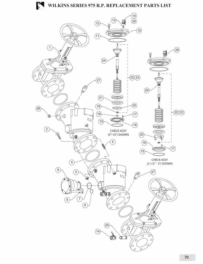
63
12
14
13
28
2
1
3
4
5
9
8
7
6
10
CHECK ASSY(4"-10") SHOWN
CHECK ASSY(2 1/2" - 3") SHOWN
11
15
18 17
15
16
17
19
21
16
20
20
22
25
14
24
24
26
27
27
28
23
22 23
WILKINS SERIES 975 R.P. REPLACEMENT PARTS LIST
79

MODEL 975 Relief Valve 2-1/2” to 10”
RELIEF VALVE COMPLETE 977-CU 9711-CU
ITEM
NO.DESCRIPTION QTY. 2-1/2”-6” 8” & 10”
1 BLEED SCREW 2 552-11A 552-11A
2 BOLT, COVER 6 5752-11 5752-11
3 BOLT 1 554-11A 554-11A
4 WASHER, DIAPHRAGM 1 977-80 977-80
5 DIAPHRAGM 1 5758-43 5758-43
6 SPRING RETAINER 1 977A-80-010F 9711A-80-010F
7 O-RING, SPRING RETAINER 1 113N 113N
8 SPRING 1 977A-33 9711-33A
9 STEM GUIDE 1 977-2 9711-2
10 O-RING, STEM GUIDE 1 230N 230N
11 O-RING, STEM 1 220N 327E-60
12 STEM 1 977-5 9711-5
13 SEAL RING 1 5758-12 9711-12
14 SEAL RETAINER 1 977-14 9711-14
15 BOLT, SENSING 1 977-11 977-11
16 BOLT, SEAT 3 5752-11A N/A
17 SEAT 1 977-18 9711-18
18 O-RING, SEAT 1 031N 036N
19 O-RING, SENSING LINE 1 018N 018N
20 O-RING, LARGE 1 033N 036N
21 O-RING, SMALL 1 022N 022N
22 RELIEF VALVE STEM ASSY. 1 977-50 9711-50
a company®
REPAIR KITS, RUBBERRK212-975R
2-1/2”- 6”
RK8-975R
8” & 10”
ITEM
NO.DESCRIPTION QTY. PART NO. PART NO.
5 DIAPHRAGM 1 5758-43 5758-43
7 O-RING, SPRING RETAINER 1 113N 113N
10 O-RING, STEM GUIDE 1 230N 230N
11 O-RING, STEM 1 220N 327E-60
13 SEAL RING 1 5758-12 9711-12
19 O-RING, SENSING LINE 1 018N 018N
20 O-RING, LARGE 1 033N 036N
21 O-RING, SMALL 1 022N 022N
REPAIR KITS
REPAIR KITS, COMPLETE
RK212-975
2-1/2”- 6”
RK8-975
8” & 10”
ITEM
NO.DESCRIPTION QTY. PART NO. PART NO.
N/A REPAIR KIT, RUBBER 1 RK212-975R RK8-975R
8 SPRING 1 977A-33 9711-33A
65
7
8
9
2
6
3
1
4
5
10
11
14
13
12
15
16
17
1819
1
20
21
22
REPAIR KITS
WILKINS SERIES 975 R.P. REPLACEMENT PARTS LIST
80

�� ������� *���,
DOCUMENT #: REVISION:BF-TG-5 8/04
Model TG-5���4�"!�����'7" 3�#��!���� �
)���*+",�;����0��
�#$./.);.�=��J�D.;;)>���$$;
;���-.>0.=��D 6�"�;& �����'7" 3�#��!���� ��)���*+",;����0������6�����6�7 ����������""�+���6�� 7�#��������;,��4����*�����'���8�� �+"�����'�4�"!�8���6���6���6�#��� �����#������"�����'7" 3�#��!���� ��)���*+"���(�;���;& ��������+"�� 7����7 �*����""�'� 3����������� ��6������� �"�6����� ������ **��6�6�+,�)��$8�)--)���6�/�����J�(
APPLICATION
CALIBRATION;���-.>0.=��D 6�"�;& �����'7" 3�#��!���� ��)���*+",;����0��������+N����6�� ���"�+���� ���������� �7 �*���� ����6��6��������+"��� �����=��� ��"�������� 7�����6��6�(�.������� **��6�6�����������+��������'�6�7 ����"�+���� ������"",(�-.>0.=������ ��"��+"��7 �����7��������"�+���� �� ��������������6�+,�6�7����(
� &����+ 6,� 7���������6�����* �"������*������"� &����6��"C����A�2�6��*����8�� ���#(�(.(����"�
5���6�!��� ��9� ��������"�����������������6��"� )������,C�OA ��(��#(�(.(�(�56�����6��9� 4�"!��C�� 7� �����6����6"��3�������"���+"�������
5��� ��"9� � ����I���6�7������C�5�9�� " ��� 6�6��P�"��������6
5�9��<�" ���"����+"��6���+�8��)$���Q�7"����7���������6%��*��� ���"����+"��� � ���*���"�5+����9�7�"����
� ��,����3������,��������6�7��������*������"����6*���7�������
� ����+"������,��������3�����G�����"�7������� *���� *����
D�G�*�*�3 �'����������� �������- �'�����*������������� ��Q�/�� ����Q�/
����*������" D "6�6�#"�����&����+ 6, ;���* �"�����/������ ������5=#;�I��)$9.������"� $#�$"��� *���
���������"��������"�����
� �� �����=����"��"�������6�N��'��
FEATURES MATERIALS
;���;& ���������+"�� 7������������7 "" 3���+��'7" 3���� !���� ��6�!����C� ��6���6�#��������#������"��)���*+"���� � �+"�����'�4�"!��)���*+"���� #��������4����*�����'���)���*+"���
TESTING
;������'7" 3�#��!���� ��;����0������""�+������!�"!�����������6�77�������"��,��(�;��������'������""�� *������ 7������A�2�6��"�������������* �"������� �����3��������� ����# (�(.(����"��5�(��# (�(.(�(������*����9���6�����������,� 7�OA ��(��# (�(.(�(56�����6��9(�;��������'������""���� �� �������� " ��� 6�6�����"����������6����6"��!�"!���3�����)$�7"����7���������6���� " �� 6�6����������� ����5��7��"�����9(�;��������'������""����"�6�������6��"����������8���"�+���� �������7��������6���"�*�����6��������� �������(�;������'7" 3�#��!���� ��;����0������""�+����-.>0.=��D 6�"�;& �(
SPECIFICATION
�.&���.�$����$
>�-��.�$����$
�E�#)������$
>�-��.�$��>$$�=$$�>$�4)>4$�5+����6�+ 6,9
�.&���.�$��>$$�=$$�>$�4)>4$
5+����6�+ 6,9
�>$$��;J�$
/.>;$��
company
ACCESSORIES
� @; �$;�@���'�;����/���������
WILKINS MODEL TG-5 BACKFLOW TEST ASSEMBLY
81

Series TK-99E Backflow Preventer Test Kit Model TK-99E Backflow Preventer Test Kit is a compact portabledevice made for testing pressure vacuum breakers, anti-spill vac-uum breakers, reduced pressure zone assemblies, and doublecheck valve assemblies. This Backflow Preventer Test Kit hasbeen designed for simplified operation and rugged reliability in acompact package. The TK-99E consists of a gauge with color-coded valves and hoses, hose adapters, shock cord for easymounting, supply pressure gauge, and a carrying case. Accuracyis +/-1% of full scale.
Features•41⁄2" (114mm) diameter face gauge with dual scale
(0-15psi/0-1bar)
• Pressure gauge measuring 0 - 200psi
•Three lightweight needle valves encased in chemical resistantbodies
• Adapters:
three 3⁄8" x 1⁄4" bushings
three 1⁄2" x 1⁄4" bushings
three 3⁄4" x 1⁄4" bushings
three 1⁄4" flared fittings
•Hoses: three 6ft (1828mm) hoses with female-threaded swivelcouplings
• 16" (41mm) securing strap
• Shock cord
• Replaceable hose filters and valve stem seals
• Durable carrying case
Pressure-TemperatureMaximum Working Pressure: 200psi (13.7 bar)
Maximum Working Temperature: 200°F (93°C)
For Backflow Testing Applications
ES-TK-99E
Job Name ––––––––––––––––––––––––––––––––––––––––––– Contractor ––––––––––––––––––––––––––––––––––––––––––––
Job Location ––––––––––––––––––––––––––––––––––––––––– Approval –––––––––––––––––––––––––––––––––––––––––––––
Engineer ––––––––––––––––––––––––––––––––––––––––––––– Contractor’s P.O. No. –––––––––––––––––––––––––––––––––––
Approval ––––––––––––––––––––––––––––––––––––––––––––– Representative ––––––––––––––––––––––––––––––––––––––––
G-TB
Watts product specifications in U.S. customary units and metric are approximate and are provided for reference only. For precise measurements,please contact Watts Technical Service. Watts reserves the right to change or modify product design, construction, specifications, or materialswithoutprior notice and without incurring any obligation to make such changes and modifications on Watts products previously or subsequentlysold.
ES-TK-99E 0643 ©Watts Regulator Company, 2006
USA: 815 Chestnut St., No. Andover, MA 01845-6098; www.watts.com
Canada: 5435 North Service Rd., Burlington, ONT. L7L 5H7; www.wattscanada.ca
Backf low Prevent ion Products
WATTS MODEL TK-99E BACKFLOW TEST ASSEMBLY
82

Series TK-9A Backflow Preventer Test Kit Model TK-9A Backflow Preventer Test Kit is a compact portabledevice made for testing all reduced pressure zone backflow pre-vention assemblies and double check valve assemblies. The TK-9A is easily connected to any RPZ device enabling accurate test-ing of ‘zone’ differential pressure, relief valve opening differential,fouled check valves or similar problems that visual inspectionscannot locate. Accuracy is +/- 2%. The unit includes a carryingcase for easy handling and accessibility.
Features • 41⁄2" (114mm) diameter face gauge with dual scale
(0 - 15psi/0-1 bar)
• Test valves: (2) ball valves(1) needle valve
• Adapters: (3) 1⁄4" threaded coupling adapters(3) 1⁄2" x 1⁄4" bushings(3) 3⁄4" x 1⁄4" bushings
• Hoses: (3) 3' (914mm) hoses with female-threaded swivel couplings
• 16" (406mm) securing strap
• Moisture resistant operation manual
• Durable carrying case
Pressure-TemperatureMaximum Working Pressure: 175psi (12.1 bar)
Maximum Working Temperature: 210°F (98°C)
For Backflow Testing Applications
ES-TK-9A
Job Name ––––––––––––––––––––––––––––––––––––––––––– Contractor ––––––––––––––––––––––––––––––––––––––––––––
Job Location ––––––––––––––––––––––––––––––––––––––––– Approval –––––––––––––––––––––––––––––––––––––––––––––
Engineer ––––––––––––––––––––––––––––––––––––––––––––– Contractor’s P.O. No. –––––––––––––––––––––––––––––––––––
Approval ––––––––––––––––––––––––––––––––––––––––––––– Representative ––––––––––––––––––––––––––––––––––––––––
G-TB
Watts product specifications in U.S. customary units and metric are approximate and are provided for reference only. For precise measurements,please contact Watts Technical Service. Watts reserves the right to change or modify product design, construction, specifications, or materialswithoutprior notice and without incurring any obligation to make such changes and modifications on Watts products previously or subsequentlysold.
ES-TK-9A 0643 ©Watts Regulator Company, 2006
USA: 815 Chestnut St., No. Andover, MA 01845-6098; www.watts.com
Canada: 5435 North Service Rd., Burlington, ONT. L7L 5H7; www.wattscanada.ca
Backf low Prevent ion Products
WATTS MODEL TK-9A BACKFLOW TEST ASSEMBLY
83

Series TK-7 Backflow Preventer Test Kit
Working Height of Tube: 44" (1118mm)Model TK-7 Backflow Preventer Test Kit is made to test the indi-vidual check modules of the Watts Series 7, 709, and 007 resi-dential dual check and double check valve assemblies. The testkit is a water column sight tube that contains three segments ofdurable 7/16" (11mm) shatterproof tubing, two brass adaptorsused to assemble the three tubing segments, and test hardwareto enable testing of Series 7, 709, and 007check modules.Model TK-7 also included a rugged simulated leather carryingcase for compactness and ease of handling.
Features• 7⁄16" (11mm) shatterproof tubing
• Two brass adaptors
• Three segments of plastic tubing
• Test hardware
• Moisture resistant instruction panel
• Durable simulated leather case
MaterialsTubes: Plastic
Adapters: Brass
Case: Simulated leather
For Backflow Testing Applications
ES-TK-7
Job Name ––––––––––––––––––––––––––––––––––––––––––– Contractor ––––––––––––––––––––––––––––––––––––––––––––
Job Location ––––––––––––––––––––––––––––––––––––––––– Approval –––––––––––––––––––––––––––––––––––––––––––––
Engineer ––––––––––––––––––––––––––––––––––––––––––––– Contractor’s P.O. No. –––––––––––––––––––––––––––––––––––
Approval ––––––––––––––––––––––––––––––––––––––––––––– Representative ––––––––––––––––––––––––––––––––––––––––
Watts product specifications in U.S. customary units and metric are approximate and are provided for reference only. For precise measurements,please contact Watts Technical Service. Watts reserves the right to change or modify product design, construction, specifications, or materialswithoutprior notice and without incurring any obligation to make such changes and modifications on Watts products previously or subsequentlysold.
ES-TK-7 0646 ©Watts Regulator Company, 2006
USA: 815 Chestnut St., No. Andover, MA 01845-6098; www.watts.com
Canada: 5435 North Service Rd., Burlington, ONT. L7L 5H7; www.wattscanada.ca
Backf low Prevent ion Products
TK-7
WATTS MODEL TK-7 BACKFLOW TEST ASSEMBLY
84

S
Bulletin 845-5 W07
��
Backflow Prev
“M
The 845 is in theBoth FCCC &
Functio���'7" 3 ;��� 0��� �� !�
Reduced Pressure PSpill Resistant Vacuu
+��'7" 3
�������
Product Features/Benefits� �!�� �� E���� 7 .���� 7� * ���'7" 3 ;�� 5�9 4�"!� ;��� 0��� ������"", ������6 7 � ;����� ���'7" 3 #� � 7� �����6 ����� =��6"� 4�"!�� 53��� ��� ;��� '�� �� �� �����6 3��� %� *��� � 7�"����
/�"��� �"�*���� ��� +� �"����6 � ���"���� ����+"� D "6�6 #"����� ���,�� ���� .*�� !�6 ��� 3��� �� ��� *����*�� ;��� �� ��6���� ��� "�*�����6 �� �"��� �"� � E��� -������,
pecifications� &��� ;,�� �������* ��77�������" #���� ���" ��F� I ���� 5� ?29 � �� #�.� A � �� ��77�������" #������� )������, R (� #(�(.(� - �'�� #�������C ��� #�.&� � 6, D������"C &"��� ����7 ���6 $������ -����6 .������"�C $# $"��� *���8 ����� �� >��� #������� &���C � ?2 � ��� #�.&� � ��� I $�6 /������C ���� = N��'�� ��6� � �� >����C ;���� 5�9 ���� A �< " � 5� � �"��6 ;�+�8 ��� ���� A �< " � �"��� +"��� )6��� � /������C 5�9 ���� 7 +���� 7������
��F� ���� � �'�(� &��� -����C �(�"+� A �(�'� ���C ����+"� D "6�6 #"������ ��F�C �� ?2 > G %2- G % :2 �� ;�*�������� >�*����� ��C D�G�*�* ���Q
FREEZING TEMPERATURES MUSTBE
Capable of performing all known teASSE, AWWA, CSA
stInstrument
Ultimate Backflow Test Kits®
Mid-WeNew Manifold Design
ention Assembly Test Kit
ODEL 845-5”
list of Acceptable gages fromHR-USC and CA-NV AWWA
ns and Applications:6� ��� ����+�"��, 7 � ������ �"" +���6� 7rinciple8 Pressure Vacuum Breaker8m Breaker ��6 Double Check Valve���!���� � ����*+"���(
(��-15 PSID / 0-100 KPA
���������
��!���� � )���*+"����"����+"� !�"!� �����9� *���*�F� �"��� 3��� ���"�8 ���68 ���(6
��� 7 � /������ I ; "�(�����
������ 0#)�( 5������6��9
��� ;���* �"�����(�6 ��� �(�( D���" #����
"����( �����6�� S2 +���� � ��"�� " � � 6�69(6 ��+�(�� !�6�6 7 � � '�� � �"" ����6��6
/A��Q(AVOIDED
st procedures including those recommended by, FCCC and HR-USC and NEWWA.
Over 30 Years of Input fromBackflow Technicians
85

�����
��������������������������������������������
Mid-WestInstrument
®
����������� ��������������� �������������������� ������������������������������
����������� ������������������������������������������������������������������������������������������������������������������������������������������������
����������� ������������������������������
������������������������� ������������������ �
�������� !"����������������#�����������������������������!�" �
#���$%��&�� $�%�'(�)� �*����������+�'(�,������ .!���/�����,������ /������1����
.!2�/�����*���������� ���������6��������
.!2�/�����*���������� ���������6�������9������������������������
�������!� ��
/����������������������:��������������;��<����������������=�.!"�>�����/�����,�����?��������� !"���������������=��
����������������������=�
#���$%��&�� $�%�������.!��/�����'(�)� �+�'(�,�����*����������,������� $�%�������@(�)� �+�'(�,)� �*����������,������ $�%�������D(�)� �+�'(�,)� �*����������,�����
��������E����������?���������<���������������
��������������������������=�
*����������9������G����,���� ������������������������''��
�J�����������������������������J������������������ ����
L��������������������������6��������=��
�����������������������
MPQX�,������,�����*����������+�MPQX�,�����$/�������%�
Z���������������� ����9���������!�[������������������
��������� �������
($����������(��)��*�'�����������\���M.]�^!!_
86

����������
*���������� ���������6�������
J�����������������������������J������������������ ����L��������������������������6��������=�
�)��`���������� ����� ������:����=�
������������������"����
MPQX�)� �*����������+�MPQX�,�������/������?����
������������������"����MP^X�)� �*����������+�MPQX�,�����
��/������?���������������������������
�PQX�)� �*����������+�MPQX�,�������/������?����
�����?����j�����6������;�
��������'"�+����$,���Z/�� ��������������%
�����?����j�����6������;�/����/����)������j����
j������� ����9��
��������'"�+���"��������������$,���Z/�� ��������������%��MqX�+�MP^X�J�=� ���P ���������6�������6��;=x�MqX�+MP^X�J�=�>+����� ����6��;=xMqX����6���������y����=
����������������������
J�����������������������������J������������������� ����L��������������������������6��������=��
/����������������������:��������������;��<���������������������������������������������������������������������������������#���$%��&�
� $�%�MPQX�)� �z�MPQX�,������ $�%�MP^X�)� �z�MPQX�,)� �� $�%��PQX�)� �z�MPQX�,)� ����������?���������<��
*���������� ���������6�������9�
����������������
� ����9�����������,���$6�������������������%
����;������
87

a companyTMZURN
DOCUMENT #: REVISION:BF-QTSET 5/08
SPECIFICATION SUBMITTAL SHEET
QT-SETQUICK TEST FITTING SET
APPLICATIONDesigned for use on Backflow Prevention Assemblies to
facilitate the connection of a Differential Pressure Test
Gauge. Quick Test Fittings Set, with their integral o-ring and
hand-tight installation, eliminate the need for wrenches and
Teflon tape. This will result in a time and material savings
to the tester and set includes all fittings needed to test any
size Backflow device.
MATERIALSBody (fittings) Brass
O-rings Buna Nitrile
Carrying Case High Density Polyethylene
FEATURESSet includes fittings sizes: 1/4”, 1/2” and 3/4”
Tear Resistant O-rings
SAE 45° Flare Fittings - SAE J513
Fittings knurled for easy gripping
Sold in convenient carrying case
Includes 3 spare O-rings per size
Case dimensions: 8 1/2”x5 1/2”x2 5/8”
Weight: 2 lbs.
DIMENSIONS & WEIGHTS (do not include pkg.)
TYPICAL INSTALLATIONSMODEL 3/4” 975XL SHOWN MODEL 4” 375 SHOWN
1/4” NPT 1/2” & 3/4” NPT (COMBINE WITH 1/4” NPT FITTING)
QTY.
PER
CASE
FITTING SIZESFOR VALVE
SIZE
DIMENSIONS (approximate)
A B C
in. mm in. mm (O-ring)
3 1/4" NPT X 1/4" Flare 1/4"-2" 1 3/64 27 7/8 22 112N
3 1/2" NPT X 1/4" FNPT 2 1/2"-4" 1 13/32 36 1 3/16 30 117N
3 3/4" NPT X 1/4" FNPT 6"-12" 1 13/32 36 1 3/8 35 120N
A
BC
A
BC
LOW SIDE HOSE
HIGH SIDE HOSE
#1 TEST COCK
#2 TEST COCK#3 TEST COCK
#4 TEST COCK
#1 SHUT-OFF
VALVE#2 SHUT-OFF
VALVE
BY PASS HOSE
LOW SIDE BLEED
NEEDLE VALVE
(behind body)
HIGH SIDE BLEED
NEEDLE VALVE
(behind body)
BLEED TUBE
FILTERS
QUICK TEST
FITTINGS
LOW SIDE HOSE
HIGH SIDE HOSE
BY PASS HOSE
LOW SIDE BLEED
NEEDLE VALVE
(behind body)
HIGH SIDE BLEED
NEEDLE VALVE
(behind body)
BLEED TUBE
FILTERS
QUICK TEST
FITTINGS
88

40-200 SERIES BLEED VALVE/SIGHT TUBE
�;���������7����� ������� !�6�6�7 ����7������� �",(� �+��� ������!������������� ���������,�� ��� �� 7�����������7����� ��3��� ����
� �������6�3��� ������������ +"���� ��� �*�'��������������� � �+��� ��� 6��������!� ��",� ����+��K����",�� "6(����
DESCRIPTION;���)� "" T��"��6�4�"!������������!�"!��6�����6�� ��� !�6��������������6�������7��"6������ 7�6 �+"������'�!�"!��+��'7" 3����!������(���FEATURES �� @���'�� ������ ����� @���'�+"��6� 77� 7��������"������� J��7�"���������" ���� ����� ��� **��6�6����J����������� ��6������
��MATERIAL SPECIFICATIONS
Part Name Material4�"!�� ������;���/������ ������ �������� ������
ORDERING INFORMATION
4 0 – 2 0 0 – B V
TYPICAL INSTALLATION
�DESCRIPTION;���)� "" T������;�+��0������6�����6�� ���6����!����"��������� ��6������������ 7�6 �+"������'�!�"!��+��'7" 3����!������(��FEATURES �� @���'�� ������ ���3���������%�Q��"+ 3��� $G����� ��� �����'�!�"!��+ 6,��� J��6����J����������� ��6������
�MATERIAL SPECIFICATIONS
Part Name Material%�Q�;���� �'�)6������ ������;�+�� #"������%�Q�$"+ 3� #"������
ORDERING INFORMATION
4 0 – 2 0 0 – S T
TYPICAL INSTALLATION
U +�=�*�C� ������ �C�U +�> ���� �C� #(�(�=�*+��C�$������C� ������������!�C�;�C� -� "���"��������+�� �C�
89

AGD AND AGD4A SERIES
AIR GAP DRAINS
This specification is provided for reference only. Conbraco reserves the right to change any portion of this specification without notice and without incurring obligation to make such changes to Conbraco products previously or subsequently sold.
DESCRIPTION The Apollo Air Gap Drain (AGD) is designed to funnel minor discharges from a Reduced Pressure Backflow Preventer’s relief valve due to line pressure fluctuations and/or minor check valve fouling, into the drainage system. Drain piping is easily attached to the AGD’s threaded bottom outlet. The AGD4A series ABS plastic AGDs have the additional option of using the outlet OD to glue on a coupling using the appropriate cement or the use of a flexible pipe coupling. Note: The AGD is NOT designed to collect the full discharge capacity of the relief valve. Please refer to Apollo literature for RP Relief Valve full discharge rates The appropriate AGD should be selected for Apollo’s Reduced Pressure RP4A, RP40 and RP4D Series backflow preventers from the table below.
Job Name:
Contractor: Job Location: P.O. Number: Engineer: Representative: Tag: Wholesale Distributor:
RP40 ¼” – 2”
RP4A ½” – 2”
RP4A Series AGD Model No. Order Code A B C OD of C D Wt.Each1/2" AGD4A1 AGD4A1 6 1/2 3 3/8 1" FNPT 1 1/4" Pipe 2 5/8 0.13/4" AGD4A1 AGD4A1 6 1/2 3 3/8 1" FNPT 1 1/4" Pipe 2 5/8 0.11" AGD4A1 AGD4A1 6 5/8 3 3/8 1" FNPT 1 1/4" Pipe 2 5/8 0.1
1 1/4" & 1 1/2" AGD4A112 AGD4A112 8 1/2 4 1/8 1 1/2" FNPT 2" Pipe 3 1/2 0.22" AGD4A2 AGD4A2 10 5 3/8 2" FNPT 2 1/2" Pipe 4 1/4 0.35
RP40 Series AGD Model No. Order Code A B C OD of C D Wt.Each1/4", 3/8", 1/2" AGD4012 AGD4012 6 1/2 3 3/8 1" FNPT 1 1/4" Pipe 2 5/8 0.1
3/4" & 1" AGD401 AGD401 8 1/4 4 1/8 1 1/2" FNPT 2" Pipe 3 1/2 0.21 1/4", 1 1/2, & 2" AGD2 40-200-X1 11 1/4 5 1/8 1" FNPT N/A 5 1/4 3.4
2 1/2" & 3" AGD3 40-200-X2 19 9 7/8 2" FNPT N/A 7 11.04" AGD3 40-200-X2 20 9 7/8 2" FNPT N/A 7 11.06" AGD3 40-200-X2 21 9 7/8 2" FNPT N/A 7 11.08" AGD4 40-200-X3 22 11/16 12 11/16 3" FNPT N/A 10 12.45
10" AGD4 40-200-X3 25 11/16 12 11/16 3" FNPT N/A 10 12.45
RP4D Series AGD Model No. Order Code A B C N/A D Wt. Eac2 1/2" - 4" AGD2 40-200-X1 14 3/8 5 1/8 1" FNPT N/A 5 1/4 3.4
6" AGD2 40-200-X1 15 7/8 5 1/8 1" FNPT N/A 5 1/4 3.48" & 10" AGD3 40-200-X2 23 3/4 9 4/5 2" FNPT N/A 7 11.0
h
RP40 2 ½” – 10”
RP4D 2 ½” – 10”

MODEL ORDERING SERIES/ DIMENSIONS WEIGHT
CODE SIZES
A B C (NPT)in. mm in. mm in. mm lbs kgs
909AGA 0881399 1⁄2 – 1⁄2" 009 3⁄4" 009M2/M3 23⁄8 60 31⁄8 79 1⁄2 13 .63 .281⁄2" – 1" 995
909AGC 0881376 3⁄4" – 1" 009/9091" – 11⁄2" 009M2 31⁄4 83 47⁄8 124 1 25 1.50 .6811⁄4" – 2" 995
909AGF 0881378 11⁄4" – 3" 009/90911⁄4" – 2" 009M1 43⁄8 111 63⁄4 171 2 51 3.25 1.472" 009M2
909AGK 0881385 4" – 6" 909 63⁄8 162 95⁄8 244 3 76 6.25 2.838" – 10" 909M1
909AGM 0881387 8" – 10" 909 73⁄8 187 111⁄4 286 4 102 15.50 7.03919 AGC 0881576 3⁄4"-1" 919 23⁄8 60 3 1⁄8 79 1⁄2 13 0.63 0.28919 AGF 0881577 11⁄4"-2" 919 43⁄8 111 8 1⁄2 216 2 51 3.5 1.6957AG 0111764 21⁄2" – 10" 957 71⁄2 190 103⁄16 258 2 51 1.50 .68957AG 0111815 21⁄2" – 10" 957 – – – – – – – –Splash Guard994AGK-P 0881397 21⁄2" – 10" 994 8 203 111⁄4 286 2 51 1.50 0.68995-AG 0439190 3" – 6" 995 5 127 8 203 2 51 – –
Air Gaps, Elbows and Test Cocksfor Reduced Pressure Zone Assemblies
Air GapsAn air gap provides the unobstructed, physical separation
between the discharge end of a potable water supply line and an
open receiving vessel.
The installation of an air gap and drain line are recommended.
ES-AG/EL/TC
Air Gap
909 OSY
Air GapA
B
C
Air Gaps, Elbows and Test Cocks
909 QT
Job Name –––––––––––––––––––––––––––––––––––––––––––– Contractor ––––––––––––––––––––––––––––––––––––––––––––
Job Location –––––––––––––––––––––––––––––––––––––––––– Approval ––––––––––––––––––––––––––––––––––––––––––––––
Engineer –––––––––––––––––––––––––––––––––––––––––––––– Contractor’s P.O. No. –––––––––––––––––––––––––––––––––––
Approval ––––––––––––––––––––––––––––––––––––––––––––– Representative –––––––––––––––––––––––––––––––––––––––––
Air Gap
Splash Guard
957 QT
IMPORTANT: INQUIRE WITH GOVERNING AUTHORITIESFOR LOCAL INSTALLATION REQUIREMENTS
Watts product specifications in U.S. customary units and metric are approximate and are provided for reference only. For precise measurements,please contact Watts Technical Service. Watts reserves the right to change or modify product design, construction, specifications, or materials with-out prior notice and without incurring any obligation to make such changes and modifications on Watts products previously or subsequently sold.
WATTS AIR GAPS & BACKFLOW TEST ACCESSORIES
91

Vent ElbowsUsed with Watts air gaps for vertical installation
of Reduced Pressure Zone Assemblies.
A
B
IRON ORDERING SERIES/ DIMENSIONS WEIGHT
BODY NO. CODE SIZES
A B Cin. mm in. mm in. mm lbs kgs
909EL-A 0881370 1⁄4"–1⁄2" 0093⁄4" 009M2/M3 — — — — — — — —1⁄2"–1" 995
909EL-C 0881380 3⁄4"–1" 009/9091"–11⁄2" 009M2 23⁄8 60 23⁄8 60 — — .38 .1711⁄4"–2" 995
*909EL-F 0881382 11⁄4"–2" 009M111⁄4"–2" 009/909 35⁄8 92 35⁄8 92 — — 2 .912" 009M2
*909EL-H 0881384 21⁄2"–3" 009/909 — — — — 2 51 — —(vertical)919 EL-C 0881578 3⁄4"–1" 919 21⁄4 57 2 5⁄8 67 — — 0.63 0.28919 EL-F 0881579 11⁄4"–2" 919 51⁄4 133 4 102 — — 2 0.9994EL-F 0881396 21⁄2"–10" 994 47⁄8 124 9 229 2 51 4 1.8
*Epoxy coated
C
Test CocksTCFor use with backflow preventers, isolation
valve for gauges, isolation valves for small
equipment lines.
• Full port ball valve design
• Screwdriver slot to open and close
• Available 1⁄8" M x 1⁄4" F (0006630) or 1⁄4" M x 1⁄4" F (0006635)
SAE-TC• Full port ball valve design
• Screwdriver slot operation
• Available 1⁄8" M x SAE (0006904)
Cap & TetherPlastic Cap & Tether(four required per backflow preventer)
• Fits 1⁄4" Female test cocks
• Plastic dust cap and rubber tether
• RK-TC 1⁄8 (0888846)
SAE-TC Brass Cap• Protects SAE-TC from dirt
and debris (0006902)
Brass Cap & Plastic Tether(four required per backflow preventer)
• Fits 1⁄8" M x SAE test cocks
• Brass dust cap with O-ring seal and
rubber tether
• RK-SAE-TC (0888845)
Watts 9093⁄4" – 2" (20 – 50mm)
Vertical (Up) Installation of Backflow Preventer
IMPORTANT:Inquire with governing authorities for local installation requirements.
Elbow
Air Gap
SAE-TC Adapter• 1⁄4" female SAE x 7⁄16" FPT
• Adapts to SAE-TC for use with pressuregauge and/or site tube
• SAE-TC Adapter (0006903)
SilverEagle TC• 1⁄2" TC for 21⁄2" – 4" (65 – 100mm)
series 757 and 957 (0007000)
• 3⁄4" TC for 6" – 10" (150 – 250mm)series 757 and 957 (0007001)
• Full port ball valve design
No. 3 TC with O-Ring• for 21⁄2" – 4" (65 – 100mm)
series 757 and 957 (0007002)
• for 6" – 10" (150 – 250mm)series 757 and 957 (0007003)
ES-AG/EL/TC 0646 © Watts Regulator Company, 2006
USA: 815 Chestnut St., No. Andover, MA 01845-6098; www.watts.com
Canada: 5435 North Service Rd., Burlington, ONT. L7L 5H7; www.wattscanada.ca
Backf low Prevent ion Products
WATTS AIR GAPS & BACKFLOW TEST ACCESSORIES
92
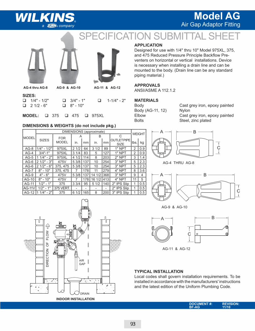
a company®
®
DOCUMENT #: REVISION:BF-AG 11/10
SPECIFICATION SUBMITTAL SHEET
Model AGAir Gap Adaptor Fitting
DIR
EC
TIO
N O
F F
LO
W
DRAIN
AIR
GAP
APPLICATIONDesigned for use with 1/4" thru 10" Model 975XL, 375,
and 475 Reduced Pressure Principle Backflow Pre-
venters on horizontal or vertical installations. Device
is necessary when installing a drain line and can be
mounted to the body. (Drain line can be any standard
piping material.)
APPROVALSANSI/ASME A 112.1.2
MATERIALS Body Cast grey iron, epoxy painted
Body (AG-11, 12) Nylon
Elbow Cast grey iron, epoxy painted
Bolts Steel, zinc plated
SIZES: � 1/4" - 1/2" � 3/4" - 1" � 1-1/4" - 2" � 2 1/2 - 6" � 8" - 10"
MODEL: � 375 � 475 � 975XL
DIMENSIONS & WEIGHTS (do not include pkg.)
TYPICAL INSTALLATIONLocal codes shall govern installation requirements. To be
installed in accordance with the manufacturers' instructions
and the latest edition of the Uniform Plumbing Code.
AG-4 thru AG-8 AG-9 & AG-10
INDOOR INSTALLATION
AG-11 & AG-12
MODEL
DIMENSIONS (approximate)WEIGHT
SIZESFOR
MODEL
A B C
OUTLET PIPE
SIZEin. mm in. mm lbs. kg
AG-8 1/4" - 1/2" 975XL 2 1/2 64 3 1/2 89 1" NPT 2 0.9
AG-4 3/4"-1" 975XL 3 1/4 83 5 127 1" NPT 2 0.9
AG-5 1 1/4" - 2" 975XL 4 1/2 114 8 203 2" NPT 3 1.4
AG-6 2 1/2" - 3" 475V 5 3/8 137 10 254 3" NPT 5 2.3
AG-6 2 1/2" - 6" 375, 475 5 3/8 137 10 254 3" NPT 5 2.3
AG-7 8" - 10" 375, 475 7 178 11 279 4" NPT 8 3.6
AG-9 4" - 6" 475V 5 3/8 137 14 1/2 368 3" NPT 9 4
AG-10 8" - 10" 475V 7 178 16 1/2 413 4" NPT 11 5
AG-11 1/2" - 1" 375 3 3/4 95 5 1/2 140 2" IPS Slip 1 0.5
AG-11V 1/2" - 1" 375 VERT. - - - - 2" IPS Slip 1 0.5
AG-12 1 1/4" - 2" 375 6 1/2 165 8 200 3" IPS Slip 1 0.5
C
A B
AG-4 THRU AG-8
AG-9 & AG-10
B
AG-11 & AG-12
C
A B
A
C
93

Some manufacturer’s designs do not lend themselves to in-line repair. They encourage you to replace their products rather than repair, adding to the stability of their business model, but not yours!
Wilkins backflow products are designed to provide the lowest life-cycle costs to our customers by offering:
Easy to perform maintenance and repair resulting in the lowest labor costs
Low-cost repair kits
We accomplish this by building simple products designed for in-line repair, requiring fewer parts and less labor than our competition.
Initial installation costs are similar for all backflow products on the market. However, once you consider the costs to test, clean and repair over the life-cycle of your backflow preventer, Wilkins is in a class by itself. Multiply these savings by the number of backflow preventers under your care and custody, and you can realize significant cost savings in your maintenance budget.
t d i d f i li i
oeovide the ering:
If you need to install backflow, Wilkins is the best choice.If you have to replace your backflow, regardless of the brand
you currently have, you will want to replace with Wilkins.
Wilkins offers grooved by grooved spools that mount between the grooved backflow body and the grooved shut off valve. These grooved spools are custom made to order and shipped pre-assembled with the backflow preventer. This single assembly backflow configuration is the most cost effective replacement solution available.
94
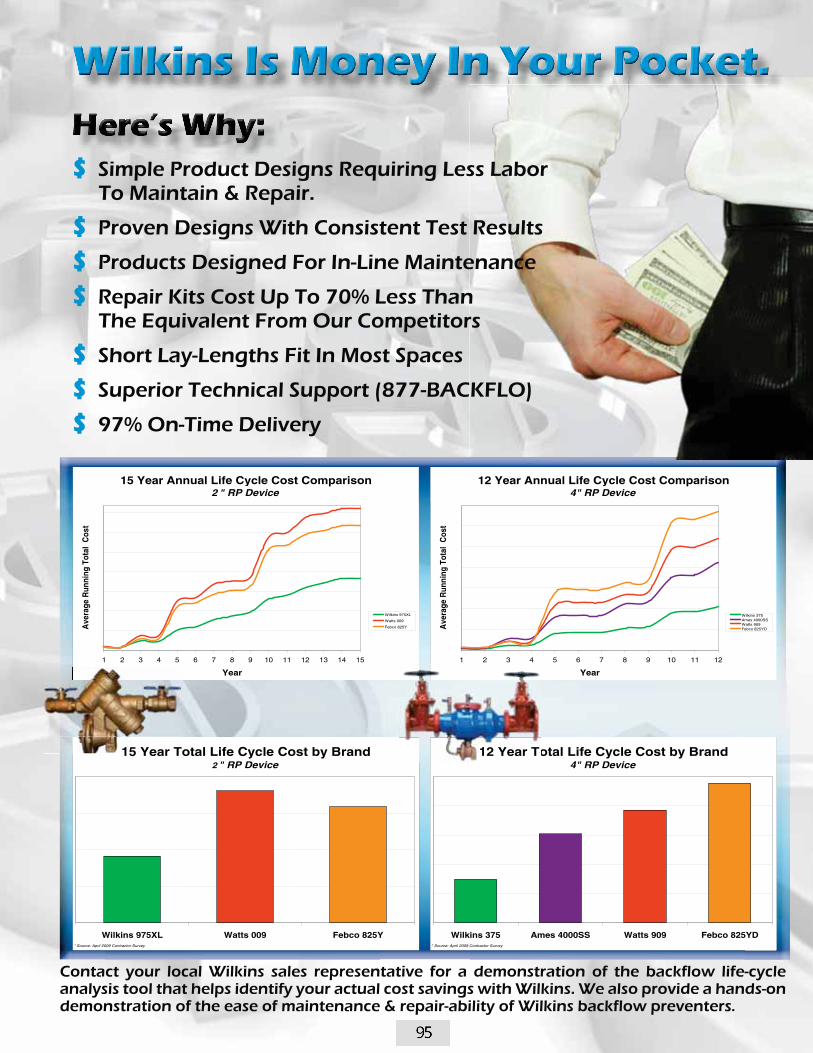
Contact your local Wilkins sales representative for a demonstration of the backflow life-cycle analysis tool that helps identify your actual cost savings with Wilkins. We also provide a hands-on demonstration of the ease of maintenance & repair-ability of Wilkins backflow preventers.
$ Simple Product Designs Requiring Less Labor To Maintain & Repair.
$ Proven Designs With Consistent Test Results
$ Products Designed For In-Line Maintenance
$ Repair Kits Cost Up To 70% Less Than The Equivalent From Our Competitors
$ Short Lay-Lengths Fit In Most Spaces
$ Superior Technical Support (877-BACKFLO)
$ 97% On-Time Delivery
15 Year Total Life Cycle Cost by Brand 2 " RP Device
Wilkins 975XL Watts 009 Febco 825Y* Source: April 2009 Contractor Survey
12 Year Total Life Cycle Cost by Brand 4" RP Device
Wilkins 375 Ames 4000SS Watts 909 Febco 825YD* Source: April 2009 Contractor Survey
15 Year Annual Life Cycle Cost Comparison 2 " RP Device
1 2 3 4 5 6 7 8 9 10 11 12 13 14 15
Year
Ave
rage
Run
ning
Tot
al C
ost
Wilkins 975XL
Watts 009
Febco 825Y
12 Year Annual Life Cycle Cost Comparison 4" RP Device
1 2 3 4 5 6 7 8 9 10 11 12
Year
Ave
rage
Run
ning
Tot
al C
ost
Wilkins 375Ames 4000SSWatts 909Febco 825YD
12 Year To15 Year T
95

Company Name ContactAddress PhoneCity emailState Zip Code
Project Location Rep AgencyRep Contact
Want Date
Order Information
Lead-Free Standard Valves Detector Assy350AR (Lead-Free not required)
375AR (Lead-Free not required)
Size 2 1/2" 3" 4" 6" 8" 10"
Inlet Gate Valve NRS OS&Y
300AR Series Order Form
Double Check 350ADAR Reduced Principle
FOR CUSTOMER SERVICE USE ONLY
Sales Order Number Part Number
375ADAR
Inlet Gate Valve NRS OS&Y
Outlet Gate Valve NRS OS&Y
Valve Type Being Replaced (Submit a separate form for each replacement backflow)
Manufacturer Model
Face to Face Dimension (exact field measurement) (± 1/16")
Signature to Guarantee Field Measurement (Purchaser) Date
300 AR Series Valve Orders Are Non-Cancellable and Non-Returnable.Signing this form guarantees the face to face dimensions to be accurate.
Wilkins QA Signature Guarantees Build Length Date
Other Details
From To From To From To2 1/2" 37 1/4" 47 1/8"
3" 38 1/4" 48 1/8"4" 40 1/2" 50" 50 1/16" 62 1/4"6" 49 1/2" 59" 59 1/16" 71 1/4"8" 64 7/8" 74" 74 1/16" 86"10" 67 3/8" 77" 77 1/16" 89" 89 1/16" 100 5/8"
Face to Face Dimension (overall lay length)Valve Size
Length Range "A" Length Range "B" Length Range "C"From To From To From To
2 1/2" 37 1/4" 47 1/8"3" 38 1/4" 48 1/8"4" 40 1/2" 50" 50 1/16" 62 1/4"6" 49 1/2" 59" 59 1/16" 71 1/4"8" 64 7/8" 74" 74 1/16" 86"10" 67 3/8" 77" 77 1/16" 89" 89 1/16" 100 5/8"
Face to Face Dimension (overall lay length)Valve Size
Length Range "A" Length Range "B" Length Range "C"
FAX or email this Order Form with the Purchase Order to:National Fire Equipment Ltd. Click here for contact information.
REPLACED ASSEMBLY
WILKINS MODEL 375AR

National Fire Equipment Ltd.
Backflow Parts - November - 2010
VANCOUVER:7972 Winston Street
Burnaby, BC V5A 2H514112 - 129 Avenue
Edmonton, AB T5L 4N5
EDMONTON: CALGARY:Bay #1, 4115 - 61 Avenue S.E.
Calgary, AB T2C 1Z2
TOLL FREE BRITISH COLUMBIA: 1-800-667-2138
VISIT OUR WEBSITE! www.nationalfire.com
Phone: (604) 420-1131Fax: (604) 420-2103
Phone: (780) 455-3870Fax: (780) 451-0926
Phone: (403) 236-5661Fax: (403) 236-2367
TOLL FREE ALBERTA:1-888-891-1008
National Fire Equipment Ltd.
Please contact the National Fire Equipment branch office nearest you for yourcopy of any of our fire protection products price list publications!
Sprinkler Products Interior Products Forestry Products
Model TG-5 - 5 ValveAssembly Backflow Test Kit
Backflow PreventionQuck Test Fittings
Backflow Test Equipment