national grid experience with composite load model (latulipe) pdf
TRANSCRIPT

Place your chosen image here. The four corners must just cover the arrow tips. For covers, the three pictures should be the same size and in a straight line.
NERC FIDVR Workshop - Panel Session – October 1, 2015
Dean Latulipe, National Grid
National Grid Experience with PSS/E Composite Load Model

Overview
National Grid has Service Territories in New England
and New York
The Composite Load Model (CMLD) Dynamic Load
model was tested on the New England system.
PSS/E Rev 32.2.4 was used conduct simulations
1

CMLD Model
2

Baseline CMLD Parameters - Load Breakdown
Load Survey conducted for New England in 2013
Summer Peak Load Breakdown:
New England Region Electronics Motor A Motor B Motor C Motor DConstant Current
Constant Impedance
Connecticut 18% 14% 12% 6% 25% 12% 13%Massachusetts – East 16% 18% 12% 7% 23% 12% 13%Massachusetts -West/Central 14% 15% 13% 8% 25% 10% 14%Maine 16% 15% 12% 9% 19% 12% 17%New Hampshire 16% 16% 12% 8% 18% 13% 17%Rhode Island 14% 15% 13% 7% 26% 11% 14%Vermont 15% 17% 11% 10% 19% 12% 16%New England 16% 16% 12% 7% 23% 12% 14%

Baseline CMLD Parameters – Motor A
Motor A: Commercial 3-phase Air Conditioners (Motor A < 250 HP)
Vtr1 - U/V Trip1 Voltage: 0.70 pu
Ttr1 - U/V Trip1 Time: 0.033 sec (2 cycles)
Ftr1 - U/V Trip1 fraction: 0.20
Vrc1 - U/V Trip1 reclose Voltage: 1.0 pu
Trc1 - U/V Trip1 reclose Time: 999 sec (no restart)
Vtr2 - U/V Trip2 Voltage: 0.50 pu
Ttr2 - U/V Trip2 Time: 0.033 sec (2 cycles)
Ftr2 - U/V Trip2 fraction: 0.70
Vrc2 - U/V reclose Voltage: 0.70 pu
Trc2 - U/V reclose Time: 0.033 sec

Baseline CMLD Parameters – Motor B
Motor B: Commercial 3-phase Pumps
Vtr1 - U/V Trip1 Voltage: 0.50 pu
Ttr1 - U/V Trip1 Time: 0.033 sec (2 cycles)
Ftr1 - U/V Trip1 fraction: 0.50
Vrc1 - U/V Trip1 reclose Voltage: 0.70 pu
Trc1 - U/V Trip1 reclose Time: 0.033 sec
Vtr2 - U/V Trip2 Voltage: 0.50 pu
Ttr2 - U/V Trip2 Time: 0.033 sec (2 cycles)
Ftr2 - U/V Trip2 fraction: 0.50
Vrc2 - U/V reclose Voltage: 0.95 pu
Trc2 - U/V reclose Time: 999 sec (no reclose)

Baseline CMLD Parameters – Motor C
Motor C: Commercial 3-phase Fans
Vtr1 - U/V Trip1 Voltage: 0.70 pu
Ttr1 - U/V Trip1 Time: 0.033 sec (2 cycles)
Ftr1 - U/V Trip1 fraction: 0.20
Vrc1 - U/V Trip1 reclose Voltage: 1.0 pu
Trc1 - U/V Trip1 reclose Time: 999 sec (no restart)
Vtr2 - U/V Trip2 Voltage: 0.50 pu
Ttr2 - U/V Trip2 Time: 0.033 sec (2 cycles)
Ftr2 - U/V Trip2 fraction: 0.70
Vrc2 - U/V reclose Voltage: 0.70 pu
Trc2 - U/V reclose Time: 0.033 sec
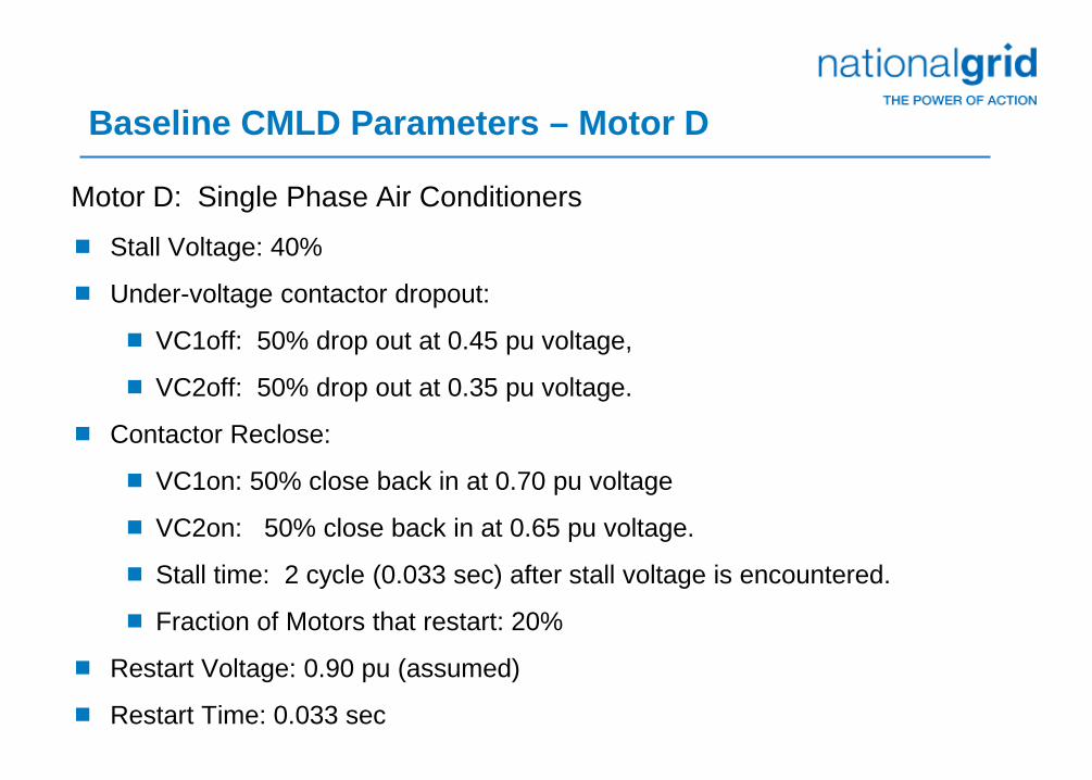
Baseline CMLD Parameters – Motor D
Motor D: Single Phase Air Conditioners
Stall Voltage: 40%
Under-voltage contactor dropout:
VC1off: 50% drop out at 0.45 pu voltage,
VC2off: 50% drop out at 0.35 pu voltage.
Contactor Reclose:
VC1on: 50% close back in at 0.70 pu voltage
VC2on: 50% close back in at 0.65 pu voltage.
Stall time: 2 cycle (0.033 sec) after stall voltage is encountered.
Fraction of Motors that restart: 20%
Restart Voltage: 0.90 pu (assumed)
Restart Time: 0.033 sec
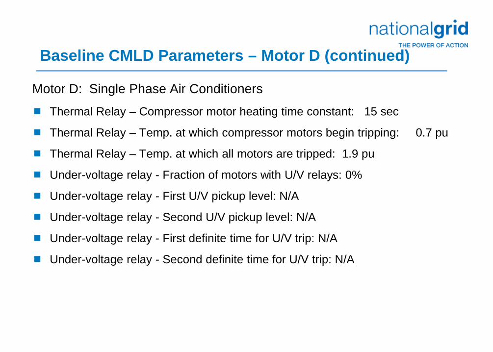
Baseline CMLD Parameters – Motor D (continued)
Motor D: Single Phase Air Conditioners
Thermal Relay – Compressor motor heating time constant: 15 sec
Thermal Relay – Temp. at which compressor motors begin tripping: 0.7 pu
Thermal Relay – Temp. at which all motors are tripped: 1.9 pu
Under-voltage relay - Fraction of motors with U/V relays: 0%
Under-voltage relay - First U/V pickup level: N/A
Under-voltage relay - Second U/V pickup level: N/A
Under-voltage relay - First definite time for U/V trip: N/A
Under-voltage relay - Second definite time for U/V trip: N/A

Sensitivity to Motor D
Vstall and Undervoltage Dropout Voltages
9
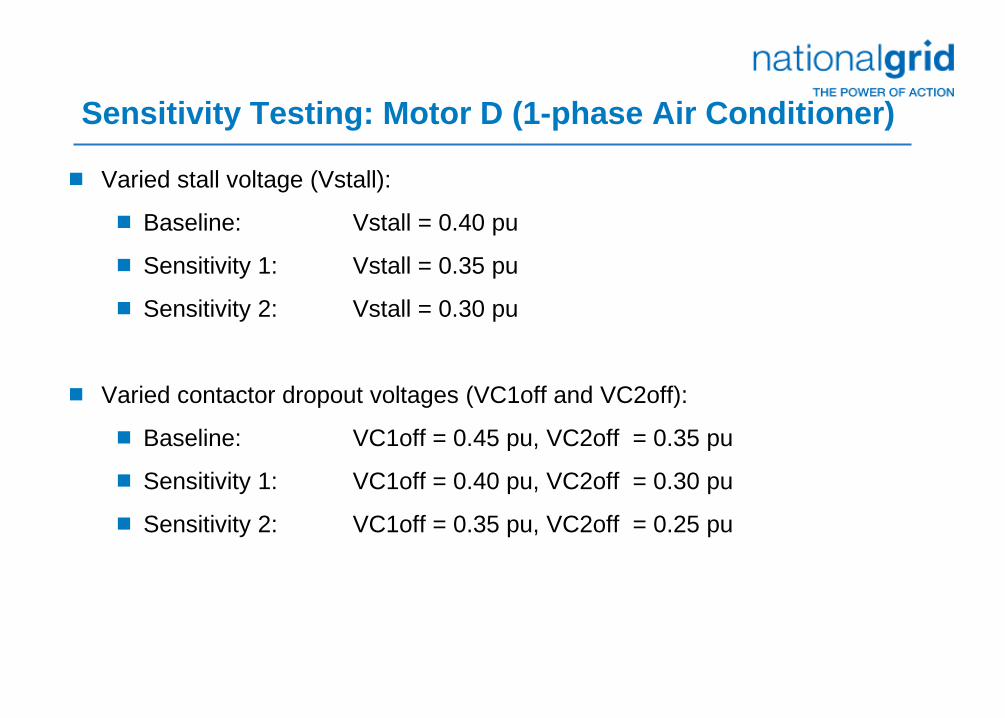
Sensitivity Testing: Motor D (1-phase Air Conditioner)
Varied stall voltage (Vstall):
Baseline: Vstall = 0.40 pu
Sensitivity 1: Vstall = 0.35 pu
Sensitivity 2: Vstall = 0.30 pu
Varied contactor dropout voltages (VC1off and VC2off):
Baseline: VC1off = 0.45 pu, VC2off = 0.35 pu
Sensitivity 1: VC1off = 0.40 pu, VC2off = 0.30 pu
Sensitivity 2: VC1off = 0.35 pu, VC2off = 0.25 pu

Test Fault
Normally Cleared 3ph Fault on 345 kV Line (4.5 cycles) in Southern New England

Results using Baseline assumptions for Motor D: Vstall = 40%, VC1off = 0.45 pu, VC2off = 0.35 pu
System stable response and well damped.
12

Results for lowering VC1off and VC2off for Motor D: Vstall = 40%, VC1off = 0.40 pu, VC2off = 0.30 pu
New York – New England Separates on second swing
13

Results for lowering VC1off and VC2off for Motor D: Vstall = 40%, VC1off = 0.35 pu, VC2off = 0.25 pu
New York – New England Separates on first swing
14

Results using Baseline assumptions for Motor D: Vstall = 35%, VC1off = 0.45 pu, VC2off = 0.35 pu
System stable response and well damped.
15
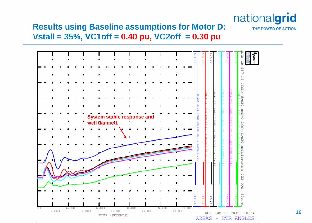
Results using Baseline assumptions for Motor D: Vstall = 35%, VC1off = 0.40 pu, VC2off = 0.30 pu
System stable response and well damped.
16
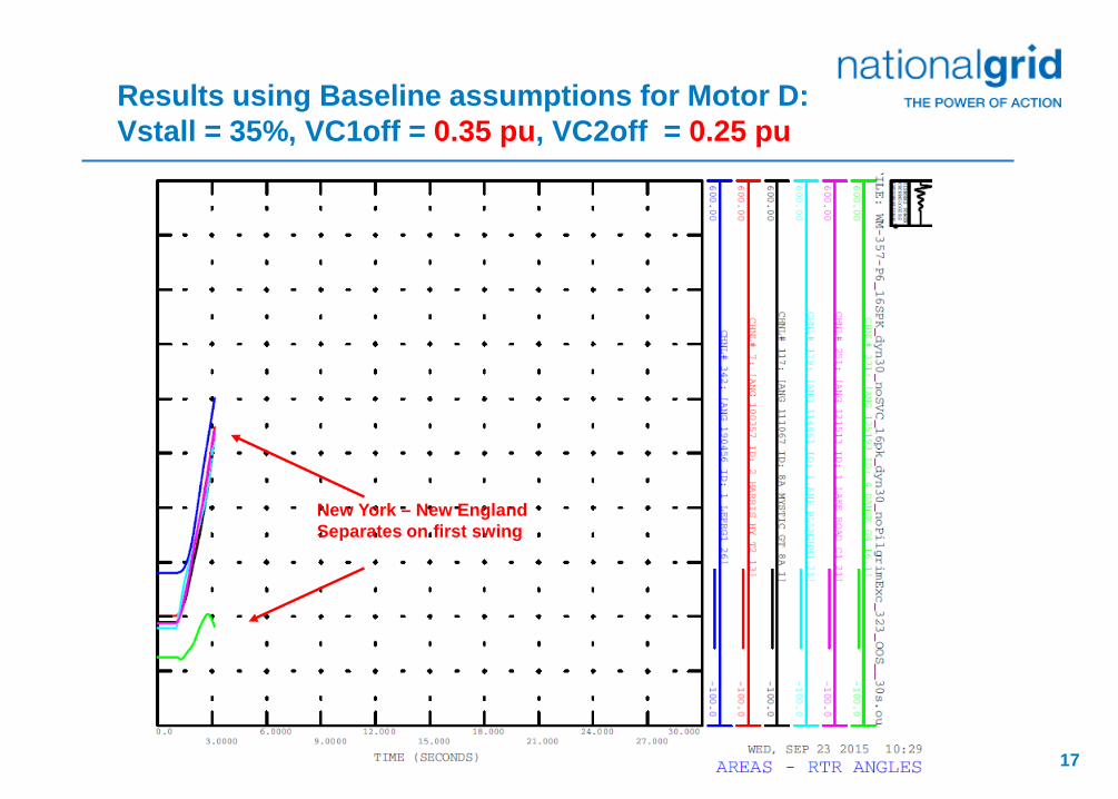
Results using Baseline assumptions for Motor D: Vstall = 35%, VC1off = 0.35 pu, VC2off = 0.25 pu
New York – New England Separates on first swing
17

Results using Baseline assumptions for Motor D: Vstall = 30%, VC1off = 0.40 pu, VC2off = 0.30 pu
System stable response and well damped.
18

Results using Baseline assumptions for Motor D: Vstall = 30%, VC1off = 0.35 pu, VC2off = 0.25 pu
System stable response and well damped.
19

Sensitivity to Motor A, B, & C
Under-voltage Contactor Dropout Voltages
20

Sensitivity Testing: Motor A, B, C U/V Trip Parameters
Baseline assumptions (Kosterev) Motor A Motor B Motor C
Vtr1 - U/V Trip1 V (pu) 0.70 pu 0.50 pu 0.70 pu
Ftr1 - U/V Trip1 fraction 0.20 0.50 0.20
Vrc1 - U/V Trip1 reclose V (pu) no reclose 0.70 pu no reclose
Vtr2 - U/V Trip2 V (pu) 0.50 pu 0.50 pu 0.50 pu
Ftr2 - U/V Trip2 fraction 0.70 0.50 0.70
Vrc2 - U/V Reclose V (pu) 0.70 pu no reclose 0.70 pu
Sensitivity parameters
Vtr1 - U/V Trip1 V (pu) 0.70 pu 0.70 pu 0.70 pu
Ftr1 - U/V Trip1 fraction 0.50 0.50 0.50
Vrc1 - U/V Trip1 reclose V (pu) no reclose no reclose no reclose
Vtr2 - U/V Trip2 V (pu) 0.50 pu 0.50 pu 0.50 pu
Ftr2 - U/V Trip2 fraction 0.50 0.50 0.50
Vrc2 - U/V Reclose V (pu) 0.95 pu 0.95 pu 0.95 pu
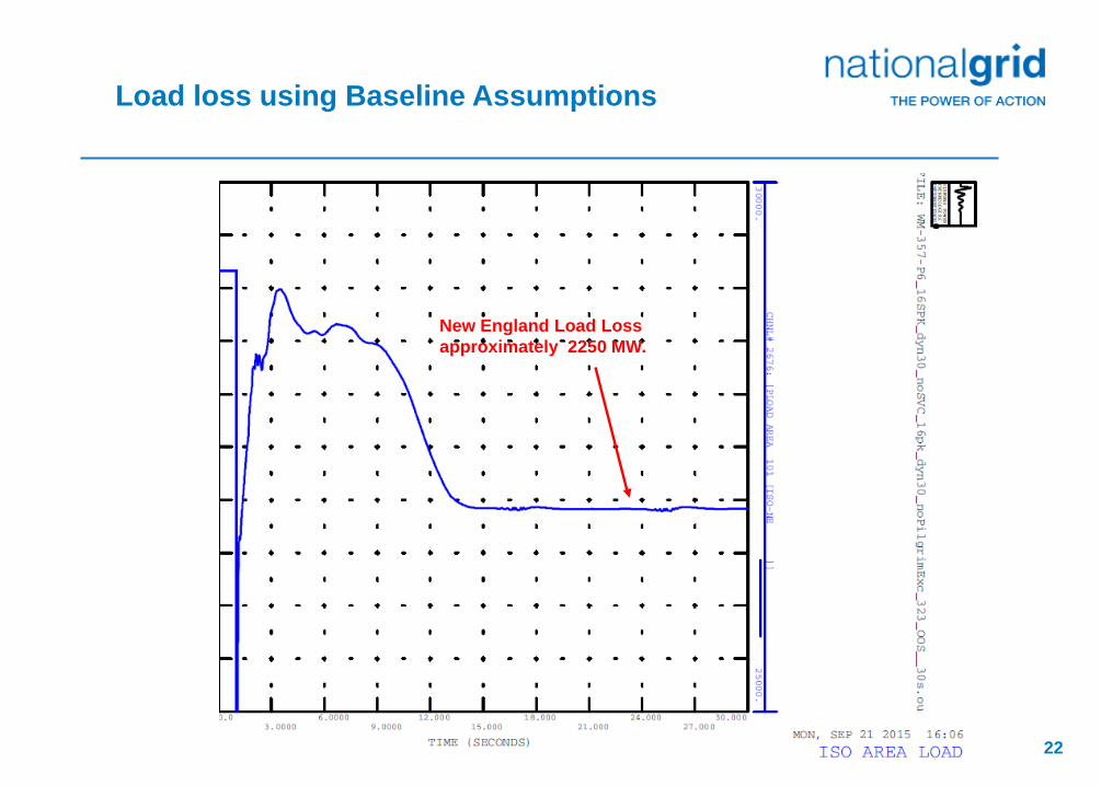
Load loss using Baseline Assumptions
New England Load Loss approximately 2250 MW.
22

Load loss using with Motor A, B, C U/V Tripping Sensitivity Parameters
New England Load Loss approximately 3700 MW.
(Total New England Load is 28,000 MW)
23

Numerical Problems
With CMPL Model in PSSE
24

120 Hz oscillations found to certain 3ph fault
120 Hz Oscillation
6.25 Hz Oscillation
25

Changed Motor A parameter LPPA from 0.104 pu to 0.12 pu
Original Motor A Parameters: LFmA - Loading factor 0.75
RaA - Stator resistance 0.04 pu
LsA - Synchronous reactance 1.80 pu
LpA - Transient reactance 0.12 pu
LppA - Sub-transient reactance changed 0.104 pu to 0.120 pu
TpoA - Transient open circuit time constant 0.095 sec
TppoA - Sub-transient open circuit time constant 0.0021 sec
HA - Inertia constant 0.05
etrqA - Torque speed exponent 0.00

Results after increasing LppA of Motor A to 0.12 pu
27

Changed Network Solution Iterations to 200
Original Network Solution Iterations: 60
Increased Network Solution Iterations to 200
Left Motor LppA - Sub-transient reactance at original value of 0.104 pu
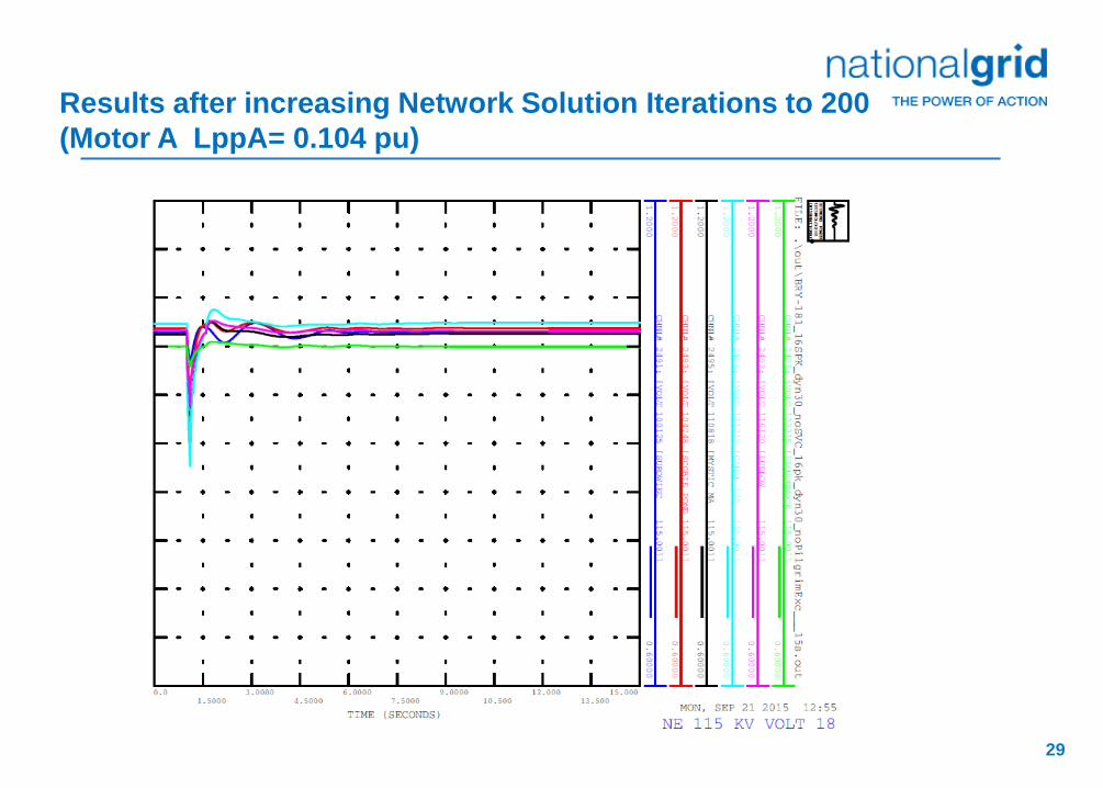
Results after increasing Network Solution Iterations to 200 (Motor A LppA= 0.104 pu)
29

Questions?
30