national radio astronomy observatorylibrary.nrao.edu/public/memos/edir/edir_198.pdf · electronics...
TRANSCRIPT

NATIONAL RADIO ASTRONOMY OBSERVATORY
GREEN BANK, WEST VIRGINIA
ELECTRONICS DIVISION INTERNAL REPORT No. 198
300-FOOT INDUCTOSYN READOUT SYSTEM
DWAYNE R. SCHIEBEL
MAY 1979
NUMBER OF COPIES: 150

300-FOOT INDUCTOSYN READOUT SYSTEM
Dwayne R. Schiebel
Introduction
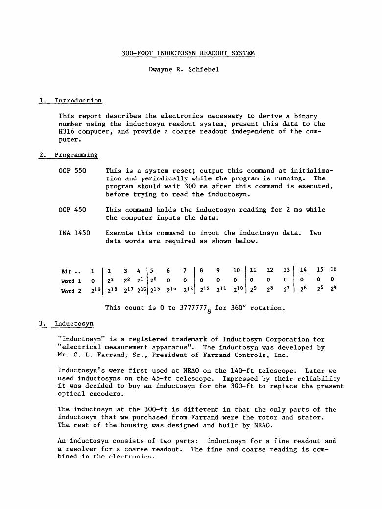
This report describes the electronics necessary to derive a binary number using the inductosyn readout system, present this data to the H316 computer, and provide a coarse readout independent of the com¬ puter .
2. Programming
OCP 550
OCP 450
INA 1450
This is a system reset; output this command at initializa¬ tion and periodically while the program is running. The program should wait 300 ms after this command is executed, before trying to read the inductosyn.
This command holds the inductosyn reading for 2 ms while the computer inputs the data.
Execute this command to input the inductosyn data, data words are required as shown below.
Two
Bit .. 1 2 3 4 5 6 7 8 9 10 11 12 13 14 15 16
Word 1 0 23 22 21 2° 0 0 0 0 0 0 0 0 0 0 0
3. Inductosyn
"Inductosyn" is a registered trademark of Inductosyn Corporation for "electrical measurement apparatus". The inductosyn was developed by Mr. C. L. Farrand, Sr., President of Farrand Controls, Inc.
Inductosyn^ were first used at NRAO on the 140-ft telescope. Later we used inductosyns on the 45-ft telescope. Impressed by their reliability it was decided to buy an inductosyn for the 300-ft to replace the present optical encoders.
The inductosyn at the 300-ft is different in that the only parts of the inductosyn that we purchased from Farrand were the rotor and stator. The rest of the housing was designed and built by NRAO.
An inductosyn consists of two parts: inductosyn for a fine readout and a resolver for a coarse readout. The fine and coarse reading is com¬ bined in the electronics.

4. Resolver to Digital Conversion
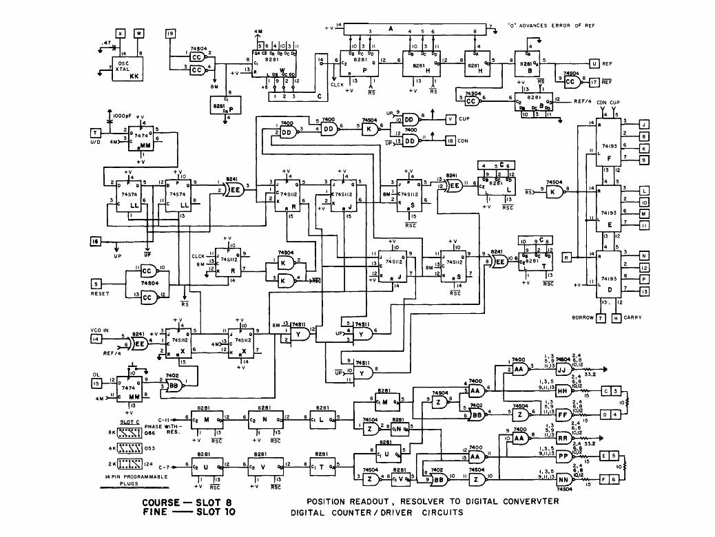
Three cards of logic are necessary to derive a coarse and fine binary number using the inductosyn and associated resolver. These three cards were designed by Ron Weimer and are identical to the ones used on the 45-ft telescope. Two of these cards are the same except for some jumper plugs. These plugs should remain with the card slot. These two cards will be referred to as digital cards.
The two digital cards are located in slots 8 and 10. Slot 10 con¬ tains the card used by the inductosyn and the other card is used by the resolver. The two jumper plugs select frequency of operation and phasing. The phasing should be adjusted so that with the inductosyn or resolver in "open loop" the error signal should be in phase with the reference. Four test points are provided on the analog card for this adjustment. This adjustment should only be necessary when chang¬ ing inductosyns.
The other card in this group is referred to as the analog card and is located in slot 9. Both resolver and inductosyn use this card.
The operation of the resolver to digital conversion is quite compli¬ cated and I will not attempt to explain it in this report. A brief explanation can be found in EDIR #149, page 8.
5. 300-ft Inductosyn Card
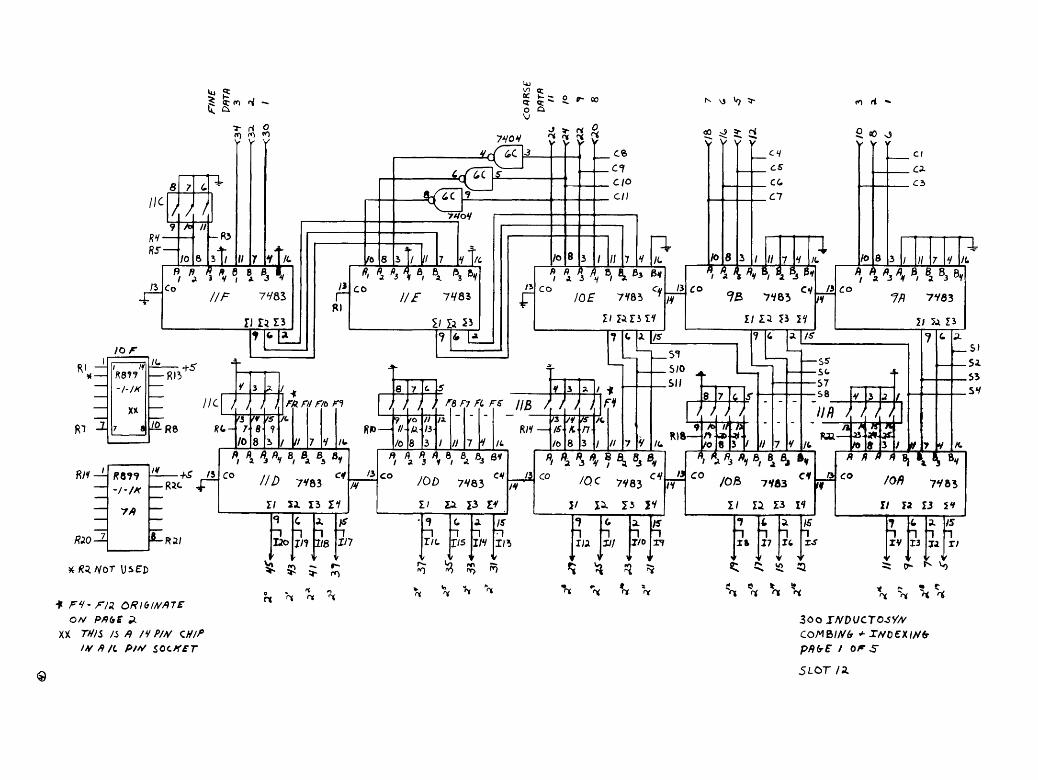
This card (built on a Shalloway card) combines the coarse and fine binary numbers from the resolver to digital converters to form a 20-bit binary number. This number can be indexed for the proper position, then fed to the computer. This card also contains the logic to generate a coarse local readout independent of the computer.
The logic that combines the coarse and fine counts involves the use of adders located in chip locations 11F, HE, 10E, 9B and 9A. The dip switch in 11C positions 6, 7, and 8 are used to adjust the "crossover" between the coarse and fine count. This adjustment is made by setting the display select switch to separate. The dip switches should be ad¬ justed such that the two middle digits in the display have a difference of four.
Indexing is accomplished by the adders in chip locations 10A, 10B, IOC, 10D and 11D. the dip switches in chip locations 11A, 11B and switches 1, 2, 3, and 4 in 11C are opened or closed to obtain the proper posi¬ tion readout as displayed by the computer.
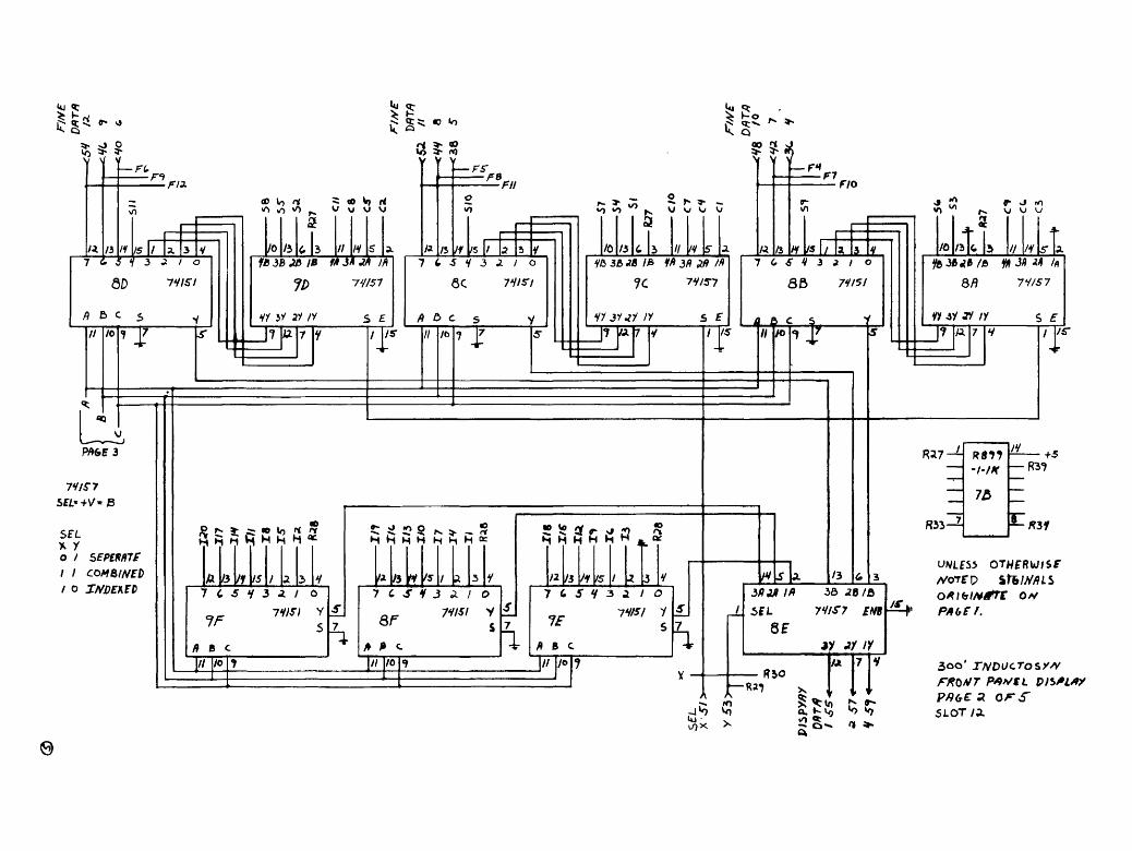
The logic on pages 2 and 3 of the "300-ft inductosyn card" is used for the readout on the front panel. This logic enables the selection of three possible displays. The three displays that can be selected are separate, combined and indexed. Separate is a display of coarse and fine independent of each other. Combined is a display of fine and coarse added together. Indexed is a display of the combined number with an index number added to it.

5. 300-ft Inductosyn Card (continued):
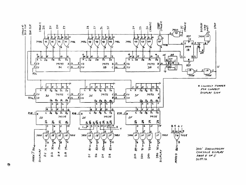
Pages 4 and 5 contain the logic necessary to convert the indexed number to degrees and tenths of degrees in BCD. The logic function on page 4 is to generate two clocks. The binary clock is generated by dividing a 2 MHz clock by 225^0» and the BCD clock is generated by dividing by 256^0' These two clocks perform the binary to degree conversion by counting down the binary number while a BCD counter is incrementing. This count¬ ing process continues until the binary counter reaches zero. These counters and a latch for the BCD number are located on page 5. Some short time after the binary counter goes to zero a new number will be loaded in the binary counter, and the process starts over. Conversion time depends on the magnitudes of the binary number.
6. Console Display Switch
When this system was originally designed it was planned to have two systems, such as we had with the encoders. After installation of the first system it was decided that only one system with a spare inducto¬ syn was all that was necessary. This card therefore has some unneces¬ sary logic.
This card contains four single-pole double-throw switches whose func¬ tion was to switch between two inductosyn systems; this function is now not necessary.
The logic that is necessary are the markers. A latch was provided for the markers to help reduce the chatter of the dip relays when the posi¬ tion is on a transition point. Two markers are available — one every even tenth of degree and one every ten degrees.
7. Balancing the Inductosyn
For optimum performance the drive to the inductosyn and resolver wind¬ ings must be balanced.
The balancing of the resolver is more straightforward so I will attempt to explain it first. The telescope will have to be moved 45° to bal¬ ance the resolver, so this should be kept in mind when positioning the telescope as the following describes. First the display select switch must be set to separate. The four digits to the left of the display are the coarse numbers. Position the telescope such that you are on a transition edge of one of the following in the coarse display:
3777-0000 777-1000 1777-2000 2777-3000
When one of these points has been reached, record the fine reading (4 digits to the right). The telescope must now be moved 32 cycles of fine (go through the fine number that was recorded 32 times). Stop on the same fine number the 32nd time. The coarse number should be 400 octal counts from the transition edge selected above. For

example, if the point chosen was 3777-0000 after 32 cycles of fine, it could be reading 377-400 or 3377-3400, depending on which direc¬ tion the telescope was moved. The resolver adjustment should be adjusted for this number.
The coarse balance of the inductosyn (fine readout system) should be performed when changing inductosyn packages. The fine balance should be checked when changing inductosyn packages or the fine digital card (J10). The fine balance procedure should be attempted on a fairly calm day since wind can affect this procedure.
The coarse balance of the inductosyn requires the use of a digital ohm meter. This meter should be used to read resistance between pins in slot 10 (card removed) as shown below:
J10-3 to J10-4 Fixed resistance.
J10-5 to J10-6 Adjust resistance equal to the resistance measured from J10-3 to J10-4.
The fine balance of the inductosyn (fine readout) will require the use of a chart recorder with the capability to "buck off" 10 V DC. The chart recorder should be connected to the output of the variable speed drive D/A converter. The telescope will have to be doing wobbles at a high rate (we used 130 min/min). The gain of the chart recorder should be such that the AC error component can be displayed. The chart record¬ ing should be examined for a periodicity to fit the formula:
42 —rri 1—7—:—/ . % = time between peaks in min. wobble rate (mm/min)
If this period is evident, the balance will have to be adjusted slightly. Observe the chart record carefully for changes of phase, using the di¬ rection change edge as a reference point. If this periodicity is still evident, but the phase has changed, the balance point was passed. This adjustment will probably require making a slight adjustment, then ob¬ serving several wobble cycles. When it is balanced, the AC error com¬ ponent will still be evident but it will not have a periodicity. This error is affected by wind and telescope balance.
8. Credits
Credit should be given to the following people:
Ron Weimer for the design of the resolver to digital converter cards and the balancing procedure.
Engineering for the design of all the hardware for the inducto¬ syn housing and mounting the inductosyn to the telescope.
Machine Shop for all the precision machine work necessary for the inductosyn.
Jerry Turner for wiring the digital chassis for this project.
H 0 03
osc XTAL
KK
74S04 • I N 2
CC.
Q
lOOOpF + y
i J J IO|3|ll
OA C2 OA Ds Dc ct
L QB PC QO
8281 _
4 5 6
10
"K "O ADVANCES ERROR OF REF
! '8 Dc DD 8281 .
TW-f
DB DC <
8281 QD
H
"FT + v RS
8281 ^ H
e 8281 0A
B
74S04 5{^6
.MM
+ v
■^ D r 0
74S74 6
LL I
&
+ v _Li£.
0 r 0
74S74
c LL
E>
SiS^-Ti 13
—igr> 3 4|DD
5 7400 74S04 101 DD 6 5[ _
7400
+ v RS Us ti
-0,
JTH CUF
8281 C2 n 0D
Da Dc B| REF/4 CON CUP
Y.T.
+v
+ 0
C74SII2
K . R
15
■^
C74SII2
J
74SII2
K R
74S04
i—i 5 8241 +V — ■^ VCO IN Sf" 8241 +vHa o
74SII2 C
REF/4 2 X
4M>iC
HV
112. JO
74SII2
[g-a * 7474
c MM —
+v
SLOT C
* 7402 9 2-S N I
114 + V
BM -11174811
IS
■H'
8M-HC74SII2 2
+v ho
K
+ v 10
8M-H 12
74SII2
_|_I4
RSC
I 10 9C 8 I
T&i Qc 0|
4—f
.74811
E> 13
+ v RSC ♦ V-
74193
F
13
■a
74193
E
■Q
■0
74193
D
■H
i—03
BORROW [TI [HI CARRY
7400 1.3 2,4 5; 9 74804 6,8
8281
8281 8281
V« ft « O fc O »
C2 M 00 PHASE WITH- I 066 RES. (i (13
+ V RSC
8281
cz N Qc Ci L o«
ci M o«
74S04 8281
1,3,5 e'.s
l» J^ + V RSC
KI^FN?
^ES 14 PIN PROGRAMMABLE
PLUGS
cj u oj cz V 00 ci T o/i
|l |I3
+ V RSC
|l |I3
+v wsc
sm. c, U 9,
74S04 8281
LL[T)^4
« ,7402 74S04 5,9 6,8
9 ^220 Si 9 ^ • nolAAy—i^^i^RRy^ |H
rt—S I ^2,4 33.2
j!—I g^ifF^'L rrn 74S04 7402 74S04
SJBB-10 ,,^^V,0 1,3,5 9.11,13
2.4 6,8
E^V-EIIH
COURSE — SLOT 8 FINE SLOT 10
POSITION READOUT , RESOLVER TO DIGITAL CONVERVTER DIGITAL COUNTER/DRIVER CIRCUITS

£>..
X-20- + 15 Y-21--15
B-2 - +5 A-J, Z-22 "GNO
RESISTORS* 1%, **5%
OP AMPS « 741
X-20 = + 15 Y-21 » -15
B-2 » +5 A-l, Z-22 «GNO
RESISTORS = 1%, *=5%
OP AMPS = 741
-15 COURSE
POSITION READOUT, RESOLVER TO DIGITAL COMPUTER ANALOG CIRCUITS/ SYNC. DET. / ERROR AMP. /VCO SLOT 9

<3>
7V/S7 SEL'O'/t /J-F/IST TA/t>
74/57
D.M D./8
D.1B
D-ve
Z5.8S
2)//? D)B D3/)
DVB
D8B
7>-
IS>- n>- n>-
PlbPLrtY
-►^3
■*«
.=L
.V
-^^
3* v-
33>-
37>-
7V/S7
TVoC
^ ?3 W£"ST /.fZ)
/y /3
/o
/>9
as 3/) 3B
/y
■?/
3y
yy
/Z)
£yj6
-^V7
■♦^
/2 ■*S3
-*S5 8
/5
7V/S7
00rt/1RK
O'MRK
Eft ST LED
//V?/y
3O0' JHDUCTOSYA/ COA/SOLE D/SPIAY 3«t>/rc/y PAGB 1 or 1 SLOT* //
rn <^ "O y V V
UJ
IK- /
Ti
R^—I /o PP k B. d t R '-h
Co 3 V , A J V
///^ 7V83
I) 13 13
tor
^ -/-/A'
/<.
6 u
/I r RI
]/6
^O2 wg
iU{lZ\3 5(3 y v y V
7VOV
5 / // 1 V «
CO IIF 7V83
2/ la 53 T\
/I
/o
N VJ ^ >
oO ^ 2; rj v v v v
. c/o
. Cfl
/0£ 7V85 r /V
/o
£ «0 O v y v
cc ,C7
TTTvvrS^ n
/«.
CO ci 7S 7*83
+5" ■RI3
_ IK
f^RB )?t- 7 10
— 7/9
/?8?? — Rjc 4^ /V
-■f^ /3
'/3 /* IS
FR Fll Fit n
I II
A [^
Rft ? ^o
/t.
CO ///) 7483 ^
E/ 5i 13 XK
-R2/ IJO !> "i n
1/7 2/8
/3
/v
/o
// yi 0--A-/3
) } } ) FtFl FLFS HZ / / ) n /¥ Is
IL
RI1 — /S
lb
»i \ % *i 8/ h b* 8y
CO /OD 7V83 ^
1/ El Z3 1^
1/7
XRZNOT \JiED
f FH- m OR)blM/)T£ ON PAbS H
/V -^/C P/V SOCKET
M «^ — f* *" ^ ^- m
ft N ^
r/c n -1 -1
lis
^
I/V
IH Jl
F1
1 Sf .5/0 .Sll
li II
/o
CI
Ch
J_ IL
llt"^3/ SaMv co
?/) 7V83
2/ 5A 15 A /$■
/{. Rift—
«/ % ^ ^ ? % % ^ CO cv /QC 7783
1/ X^ 13 JV
/5
113
1 n i/a
6
n SII
n T/o
/J /y
m. /O
77"7Sr
8 //
-SS"
■57 •S8
//^ m AttKK\*r*i
CO CI /OB 7*83
II Zi 13 H
IS "I inn
17 16
r*
jya— as. ^. ji /C |A> « 3 /Jj/ 7 y
.si 51
.53 SV
/» ^ /* A BJ ^ ^ Bv
^0 /^ 7V83
r/ za 13 54 /£ n
TV "1 "I 1 1
13 Ti
IS
TI
t s ^ S> fc U rt ri rx ri
0- ^ ^0
3oo J/VDl/CTOJV/V
pftb-E I 0^ S
SLOT /A
Iy <t
t2:
^ O O vo > * V V v ■FL
■F't Fl* 00 Vo ri *» w-> *0
I*, li II IS I 1 I, 5 1 2> 1 I o
QO 7 fist
ft e> C 5
I TT
71IS7 S£L*+V*B
SEL x y 0 / sEPtnirrf 1 I COMBINED I 0 INDEKED
©
/o lb * 3 // IH fB 3B J3 IB M 3* M lA
HI 3* ay /y
J? |JU|7 Iy S £
7
o io
y v
/a
• rr
Q A* ^
•FB Fll
/3 j/f |/5 7 4 ^ V 3 i /
6C 7V/r/
ft b C
I /«" /t> T
/o /3
SI
6 3
\j w o
// ^V Vfl 38 ^fl 73 f^ 3/9 ,2/9 //»
7c 7y/5-7
HI 3i4l IV S E 1*7 y
& ** i « • W) i* ft H M <i H h H 4C
ENt^
7~ps
«
$ — F* F7 F/O
/5 1 (. € M 1 l I
8B 7y/5/
4-& ^F^
■J Ml
/0 ill /y 5-
Qft 7i/S7
yy jy jy /y s £ A TlTr
RJ7
^33-^
R87?
7^
/y +5 83?
^/■ur
a. KVJ 'o w>
UNLESS OTWFRW/SF //OTFP sf6/y/?i.s 0*\tslM4TE OH PAbEr.
FRtiNT P**tL vntiA? pfHxE zorS SLOT /A

lllZl
8 Pit* CHIP
IH n /v ft// i oc IH
■I&-J1
46
JoJT
joo JL 15
IKHZ
ft g B
C/A
c.
li
I3
RSI
#OLt> 10 >-
REsrr
- 8(.>
/.OG«)i KESFT 76>.
IHH
(pfltt a") x
X- + V ^Of? COlAMNEb
FIND iNDEXZb
7HIH
88ao ^^/VS R3a 1
T-T 7^37
RiiC R3A
7V37 T-r9 7y37
8830 R3?
1HIH
7HIH
7HIH
DlSPLftY
STR06E
VlbPLftY MULTlPLEKMb
VISPLRy
SELECT ■^5C. fl
-^58 B
PISPLBV VftTfi
>CI 8
^7^ //Oifi
^88 RESFF
SEPSRfilE
|8|1|a|i|
Coi
8 ' /VO£X£D laiYiai 'l
0 0 0 ci a / ' / / / i 1 s / 0 CJ CI cs 0 0 5/ 3A 0 0 n T3L T JL Q Ct O C6 O 55 VI 55 o 13 11 xs
T 3 0 ct C>d c# O St 57 U 0 rt Z7U 7 ¥ o s? y s*/ 0 Jl M s// 0 npUiil / J orvrj* .OHfsn lolvMt/rl / & 0 ?7 [tM IgFIF^ 5H 7 o mlmm ^ ■frP ̂
._-. ot y
0 / 2 3 V S 6 7
DlSPLfiY
3oo' IWDUCTOSY/S
FHONT PAHEL D/Sn**
SLOT/a
9)

<2>
7V08
I KHZ (PfibES)
START.
r PA(,CI) 1/ _
II » 5/«»//
7lfOY
$
7V0O
e>cD CLK
1*
7H00
>b
P ^ <? 7H7V bF
c 9| /«
2> 6/// CLK
/3
X/ 300' SNDOcTosy/*
CONSOLE oisn#y
3L.OT/5L
# covvctr TUMPSF F'O* CoyfyfrcT
300' ZNDVCTOSYN COA/SOL£ D/$Al4/ PAbE s-ors SLOT/I

® 7437
<«>**>'&—EE^ OCPLS +
7^03
^ 7 DRL//V-
OCPLS-
RRL;^- C7>3
A/STCL- V^y- 7Yoy
OCP Lit.
7H2 7 LF
7V/2 3 /o
+5. /y 33^.- oo/
L_
/ 7
7 6
RI /
H81J /V
R3 -l-IK
/V
+5
B
ci*.
fi
/a.
R^
i_r
7yo8 ' 8830 RE5ET
-> c -
RV
INDUCTSYAf /VS/C TMTEKFAce PR(,E I OF I
HZIC SLOT//

••I—It
LPM COOO 7^^VSI5Tor5 3*31*1
PRE ftHP
J8-3
79-H
res RESOLVER ftDJVST
vTS-fc
.7/0-3
J/0-5
T»/
DeTftIL ft ti
-O <**• TO
-O 'M*—LQ
c T O t ^ »o
/o
A 5
JNWCTOSYN ^D7U3T cr
PI
COflRSf S/A//9
51/78
COflRSF C05/>
6
COAR5E ERR ft
EFRb
FINE SIN Pi
SIN B
FINE C05 /?
C05 B
+ /S
C>Nf>
FINE ERR A
ERR B
JBI-H -
TBI-8-
76'A -
TBKT-
Tflf-D-
TQ-A -
J^-V -
77-/8 ■
TB/-/C
7/0- V
7/0-/
TBI-L
r/o-t T/O-/
RS. -
RS,—
7^-D
Al
A/
/^
W
BlACK
tjJMin
ALACK Ttfice*
_&*£ UlUlTt
6P£f/V TITPCgR
PgQWV HUpCffR
/yo TffflcER
yfiLpU/ TRfilZ*
rftt TtACER
0*AVte T*A<f*
fit AC A-
UlMTt
5C. F//V i'tCO
/<fy a/6 p/y /
SMALL PIN 7
3/- /Hlka- IS P '+6ULKHEAt>
61- /If638-/5 5 —>C/*fii.f
300 XVDUCTOSW
£"^ST C/?61F
®