natural gas vehicle fuel - trunity gas & technologies enabling natural gas transportation fuel...
TRANSCRIPT

American Gas & Technologies Enabling Natural Gas Transportation Fuel
Natural Gas Vehicle Fuel
Reduces carbon monoxide emissions 90%-97%
Reduces carbon dioxide emissions 25%
Reduces nitrogen oxide emissions 35%-60%
Potentially reduces non-methane hydrocarbon emissions 50%-75%
Emits fewer toxic and carcinogenic pollutants
Emits little or no particulate matter
Eliminates evaporative emissions
LIBERTY STATIONTECHNICAL BROCHURE
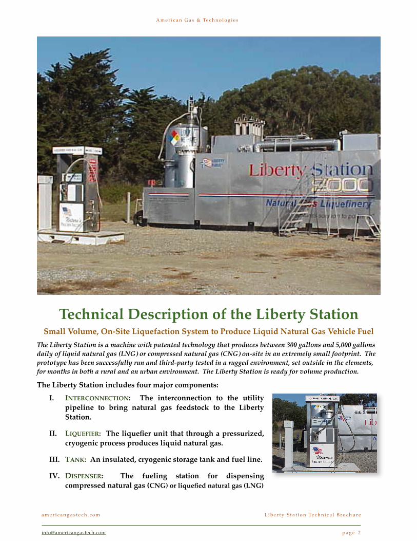
Technical Description of the Liberty StationSmall Volume, On-Site Liquefaction System to Produce Liquid Natural Gas Vehicle Fuel
The Liberty Station is a machine with patented technology that produces between 300 gallons and 5,000 gallons daily of liquid natural gas (LNG) or compressed natural gas (CNG) on-site in an extremely small footprint. The prototype has been successfully run and third-party tested in a rugged environment, set outside in the elements, for months in both a rural and an urban environment. The Liberty Station is ready for volume production.
The Liberty Station includes four major components:I. INTERCONNECTION: The interconnection to the utility
pipeline to bring natural gas feedstock to the Liberty Station.
II. LIQUEFIER: The liquefier unit that through a pressurized, cryogenic process produces liquid natural gas.
III. TANK: An insulated, cryogenic storage tank and fuel line.
IV. DISPENSER: The fueling station for dispensing compressed natural gas (CNG) or liquefied natural gas (LNG)
a m e r i c a n g a s t e c h . c o m! L i b e r t y S t a t i o n Te c h n i c a l B r o c h u r e
[email protected] ! p a g e 2
A m e r i c a n G a s & Te c h n o l o g i e s

Flow Diagram of the LiquefierThe principal elements of the Liberty Station Liquefaction System are
labeled in the diagram and described in the list below:
1. Tri-Tower regenerating molecular sieve bed2. Multi-stage high pressure compressor3. Natural gas internal combustion engine4. Gas chiller using mechanical refrigerant5. Separator for heavy hydrocarbons6. Main Liquid Methane/Gaseous Methane counter current heat exchanger7. Computer controlled JT valve assembly8. Cryogenic Liquid Methane storage vessel, with secondary containment9. Return cool gas counter current heat exchanger10. LNG/CNG dispensing station11. Card lock12. Data acquisition, communication, computer management system
!
a m e r i c a n g a s t e c h . c o m! L i b e r t y S t a t i o n Te c h n i c a l B r o c h u r e
[email protected] ! p a g e 3
A m e r i c a n G a s & Te c h n o l o g i e s

Liberty Station FeaturesThe challenges of small volume liquefaction
While the process of liquefying natural gas to produce liquid natural gas is fairly well understood, the ability to produce liquid natural gas in small volume and in an extremely small footprint is quite challenging. Years of testing various methods and the evolution surrounding three prototypes have led to the patented technology in the Liberty Station. The secret to AGT’s exceptional know-how and patents lies in the years of work and more than $40 million in cash, equipment, and labor used to develop the liquefaction system.
Notably, the fuel tank and the fuel dispensing pump are specialized for storing LNG but are, generally speaking, relatively straightforward. The principal difference in the fuel tank is that it is insulated, much like a thermos, which preserves the cold state of the LNG. Further, it provides secondary containment for safety.
The system’s advantages are in five principal areas:
I. SINGLE LOOP COOLING: Efficient processing in a single loop refrigeration cycle;
II. SECONDARY CONTAINMENT: The entire unit features built-in secondary containment of all fluids;
III. BY-PRODUCTS AS FUEL: Consumption of the process by-products to fuel its own engine and create clean emissions;
IV. COMPUTERIZED CONTROL: Complete computerized control and remote sensing to allow operator free maintenance;
V. NO TRUCKING: Elimination of the need for trucked distribution of either feedstock natural gas or finished.
a m e r i c a n g a s t e c h . c o m! L i b e r t y S t a t i o n Te c h n i c a l B r o c h u r e
[email protected] ! p a g e 4
A m e r i c a n G a s & Te c h n o l o g i e s

I. Single Loop CoolingThe AGT refrigeration process is performed in a single loop rather than the three-stage process typically used at large LNG production plants. The system uses a standard coolant and the nitrogen intrinsically contained within the natural gas feedstock itself to cool the natural gas to as much as -260o or approximately -200o under modest pressure of less than 100 psi. This unique technique reduces the amount of processing and the space required to cool the natural gas, making it economical for small volume processing. Key to this processing is the extensive use of automated digital control systems to regulate aperture sizes and pressure through feedback provided by sensors installed in critical locations within the process loop.
II. Secondary ContainmentThe entire system, including the liquefaction system and the fuel dispensing station, features built-in secondary containment of all fluids. This provides for superior safety as all leaks would be self contained. In addition, the user would not be exposed to the cold
elements of the production process providing for a completely comfortable experience with the machine and the dispensing unit. Finally, the unit contains numerous sensors to notify of any leaks from the primary to the secondary containment.
This feature helps preserve the small footprint of the Liberty Station by eliminating the need for external barriers or containments.
III. By-Products As FuelA triple tower molecular sieve is used to separate the water and CO2 from the stream before liquefaction begins. As the cooling begins, the higher hydrocarbons liquefy first. A coalescent filter is used to drop out the associated higher hydrocarbons including propane, butane, pentane, hexane, and ethane. These by-products are then used by the system’s own combustion engine as fuel. Continuing the process, the temperature is further reduced and the pressure increased to liquefy the methane. The nitrogen, which is still in a gas state, is pulled off the top after the natural gas is liquefied. Leaving the nitrogen in the stream until after liquefaction
is unique to AGT, is included in AGT patents, and helps to accelerate the cooling process. Balancing the nitrogen in the system by drawing it out as the methane liquefies is also a patented technique along with more than 60 other patented claims. The nitrogen is pulled off along with a stream of super cooled natural gas and this combination is fed through the combustion engine and is used as fuel. The combustion engine of the Liberty Station burns all the hydrocarbons and dispenses clean nitrogen safely to the environment. Moreover, the removal of contaminants from the LNG process stream yields ultra-pure methane or 99.9% pure CH4 as the finished product of the Liberty Station process. Such pure LNG is ideal for transportation fuel as it will not stratify and therefore will not be damaging when used in the vehicle engine.
IV. Safe ControlTo make all the sophisticated processing of the Liberty Station happen reliably and safely, a highly automated control system is used. This computerized control system monitors more than 100
The Liberty Station is uniquely capable of liquifying natural gas in a small footprint to enable fleet use of
natural gas transportation fuel.
The Five Liberty Station Advantages
a m e r i c a n g a s t e c h . c o m! L i b e r t y S t a t i o n Te c h n i c a l B r o c h u r e
[email protected] ! p a g e 5

The System Includes Considerable Know-Howsensors, including infrared and ultraviolet monitoring, to provide remote intelligence as to the system’s status. The system can shut itself down or can be shut down remotely if there were a fire, leak, or other potential hazard. The Liberty Station requires no local operator and can provide information on production, dispensing, safety, or potential failures to the AGT server. Such information can also be sent to the customer’s server for their review in real time. Further, to enhance safety, built-in secondary confinement systems house all fluids to prevent leaks of potentially toxic or flammable
fluids. The system is vacuum jacketed, which prevents the cold process from being exposed to the elements or to the user. Externally, the unit performs much like a standard gasoline fueling pump thus creating a comfortable and safe user experience.
V. No Need For Trucking The Liberty Station receives its natural gas feedstock directly from the utility company pipes – an extensive network that enables virtually the entire U.S. for supply of natural gas. Moreover, since the production is local, on-site where the fleet vehicles need it, no trucking distribution of the
finished LNG is required. This localized production also precludes the need for large storage tanks. When fuel storage tanks are less than 2,000 gallons, as is the case with the Liberty Station 300 and 1875, the municipal permitting process is typically done over-the-counter. Moreover, because the unit features built-in secondary containment the requirement for berms to contain leaks or for safety is eliminated. Without having to accommodate vast storage or large delivery trucks or extra spacing around property lines, the footprint of the Liberty Station remains very small.
a m e r i c a n g a s t e c h . c o m! L i b e r t y S t a t i o n Te c h n i c a l B r o c h u r e
[email protected] ! p a g e 6
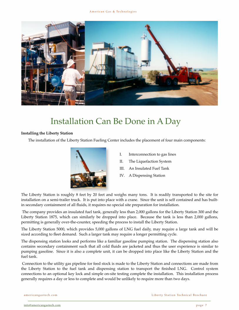
Installing the Liberty Station
The installation of the Liberty Station Fueling Center includes the placement of four main components:
I. Interconnection to gas lines
II. The Liquefaction System
III. An Insulated Fuel Tank
IV. A Dispensing Station
The Liberty Station is roughly 8 feet by 20 feet and weighs many tons. It is readily transported to the site for installation on a semi-trailer truck. It is put into place with a crane. Since the unit is self contained and has built-in secondary containment of all fluids, it requires no special site preparation for installation.
The company provides an insulated fuel tank, generally less than 2,000 gallons for the Liberty Station 300 and the Liberty Station 1875, which can similarly be dropped into place. Because the tank is less than 2,000 gallons, permitting is generally over-the-counter, speeding the process to install the Liberty Station.
The Liberty Station 5000, which provides 5,000 gallons of LNG fuel daily, may require a large tank and will be sized according to fleet demand. Such a larger tank may require a longer permitting cycle.
The dispensing station looks and performs like a familiar gasoline pumping station. The dispensing station also contains secondary containment such that all cold fluids are jacketed and thus the user experience is similar to pumping gasoline. Since it is also a complete unit, it can be dropped into place like the Liberty Station and the fuel tank.
Connection to the utility gas pipeline for feed stock is made to the Liberty Station and connections are made from the Liberty Station to the fuel tank and dispensing station to transport the finished LNG. Control system connections to an optional key lock and simple on-site testing complete the installation. This installation process generally requires a day or less to complete and would be unlikely to require more than two days.
a m e r i c a n g a s t e c h . c o m! L i b e r t y S t a t i o n Te c h n i c a l B r o c h u r e
[email protected] ! p a g e 7
A m e r i c a n G a s & Te c h n o l o g i e s
Installation Can Be Done in A Day
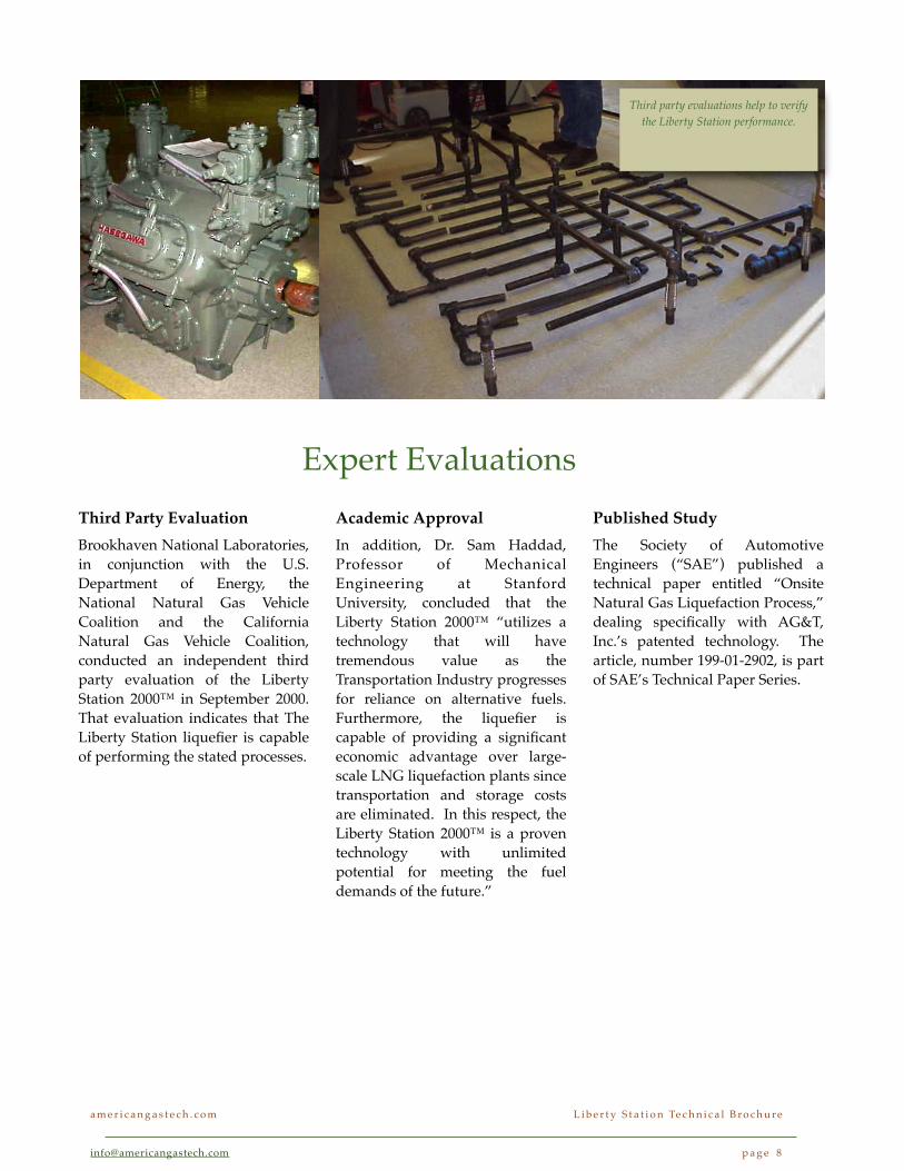
Third Party Evaluation Brookhaven National Laboratories, in conjunction with the U.S. Department of Energy, the National Natural Gas Vehicle Coalition and the California Natural Gas Vehicle Coalition, conducted an independent third party evaluation of the Liberty Station 2000™ in September 2000. That evaluation indicates that The Liberty Station liquefier is capable of performing the stated processes.
Academic ApprovalIn addition, Dr. Sam Haddad, Professor of Mechanical Engineering at Stanford University, concluded that the Liberty Station 2000™ “utilizes a technology that will have tremendous value as the Transportation Industry progresses for reliance on alternative fuels. Furthermore, the liquefier is capable of providing a significant economic advantage over large-scale LNG liquefaction plants since transportation and storage costs are eliminated. In this respect, the Liberty Station 2000™ is a proven technology with unlimited potential for meeting the fuel demands of the future.”
Published StudyThe Society of Automotive Engineers (“SAE”) published a technical paper entitled “Onsite Natural Gas Liquefaction Process,” dealing specifically with AG&T, Inc.’s patented technology. The article, number 199-01-2902, is part of SAE’s Technical Paper Series.
Third party evaluations help to verify the Liberty Station performance.
a m e r i c a n g a s t e c h . c o m! L i b e r t y S t a t i o n Te c h n i c a l B r o c h u r e
[email protected] ! p a g e 8
Expert Evaluations

Patent 5327730
Method and apparatus for liquifying natural gas
for fuel for vehicles and fuel tank for use therewithPatent 5327730 Issued on July 12, 1994; Estimated Expiration Date: May 12, 2013.
Abstract
Method for liquifying natural gas comprising regulating the pressure of the natural gas from a pressure ranging from 0-25 psig. Contaminants are filtered out of the regulated natural gas. The natural gas is then compressed to a higher pressure. At least a one-stage heat exchange is performed with the compressed natural gas by utilizing a coolant to provide a cooled compressed natural gas. A Joule Thompson valve is used to liquify at least a portion of the cooled compressed natural gas. The liquified natural gas is stored in a dewar. Unliquified natural gas passing from the dewar is utilized to provide cooling of the natural gas during the heat exchange. The unliquified natural gas is then recompressed. The recompressed natural gas is subjected to the same steps to liquify an additional portion of the recompressed natural gas.
Inventors
Myers, Albert H.
Tate, Jr., Raymond E.
Lee, Harold M.
Sfinteanu, Dragos
Assignee
American Gas & Technology, Inc.
Application
No. 060269 filed on 05/12/1993
US Classes:
62/614, 62/7
Examiners
Primary: Capossela, Ronald C.
Attorney, Agent or Firm
Flehr, Hohbach, Test, Albritton & Herbert
International Class
F25J 001/00

Patent 5327730
Method and apparatus for liquifying natural gas
for fuel for vehicles and fuel tank for use therewithWhat is claimed is:
1. A method for liquifying natural gas from natural gas comprising regulating the pressure of the natural gas from a pressure ranging from 0-25 psig, filtering contaminants out of the regulated natural gas, compressing the natural gas to a higher pressure regulating the higher pressure of the compressed natural gas to a predetermined pressure, filtering the compressed natural gas to remove any remaining foreign matter from the compressed natural gas, performing at least a one-stage heat exchange with the compressed natural gas by utilizing a coolant to provide a cooled compressed natural gas, utilizing a Joule Thompson valve to liquify at least a portion of the cooled compressed natural gas, storing the liquified natural gas in a dewar, utilizing the unliquified natural gas passing from the dewar to provide cooling of the natural gas during at least one heat exchange and thereafter recompressing the unliquified natural gas and subjecting the recompressed natural gas to the same steps to liquify an additional portion of the recompressed natural gas.
2. A method as in claim 1 wherein the natural gas is comprised of various constituents including methane, butane and propane and wherein the constituents of the natural gas other than methane are separated from the natural gas before the heat exchange.
3. A method as in claim 2 together with the step of utilizing at least one of the components of the natural gas separated from the natural gas to provide energy for the compression step.
4. A method as in claim 1 together with the step of mixing refrigerant carrier gas with the natural gas to increase the efficiency of liquification of the natural gas.
5. A method as in claim 4 wherein the refrigerant natural gas is maintained in a gaseous state throughout the method.
6. A method as in claim 4 wherein said refrigerant natural gas is selected to have a liquifying temperature which is less than the liquifying temperature of the natural gas so that the refrigerant carrier gas always remains in a gaseous phase during the process.
7. A method as in claim 1 wherein the compressed natural gas is subjected to at least two heat exchangers before passing through the Joule Thompson valve.
8. A method as in claim 7 together with the step of providing a closed loop cooling system for at least one of the heat exchangers.
a m e r i c a n g a s t e c h . c o m! L i b e r t y S t a t i o n Te c h n i c a l B r o c h u r e
[email protected] ! p a g e 10

Patent 5327730
9. An apparatus for liquifying natural gas from a source of natural gas, a regulator for receiving the natural gas and supplying an output pressure ranging from 0-25 psig, a filter for filtering foreign contaminants from the natural gas, a compressor for compressing the filtered natural gas to a desired higher pressure, a regulator for regulating the pressure of compressed natural gas, a filter for filtering the regulated compressed natural gas for removing any remaining foreign matter, a heat exchanger for receiving the compressed natural gas and for cooling the compressed natural gas, a Joule Thompson expansion valve for receiving the cooled compressed natural gas and expanding the cooled compressed natural gas for liquifying at least a portion of the cooled compressed natural gas, a dewar for storing the liquified natural gas discharged from the expansion valve, means connected to the dewar for receiving unliquified natural gas and for passing it through the heat exchanger for providing cooling to the compressed natural gas in the heat exchanger, and piping means connected to the main heat exchanger for taking the unliquified natural gas from the heat exchanger and supplying it to the compressor for recompression.
10. Apparatus as in claim 9 wherein said means for supplying a coolant to the primary heat exchanger includes a source of cooled gas.
11. Apparatus as in claim 9 wherein said means for providing coolant to the heat exchanger includes a closed loop or recirculating a gas through the heat exchanger.
12. Apparatus as in claim 9 wherein said apparatus is mounted on a platform so that it can be moved from one location to another.
13. Apparatus as in claim 12 wherein said platform is in the form of a wheeled trailer.
14. Apparatus as in claim 9 wherein said apparatus is mounted on a platform and wherein said apparatus includes a liquid natural gas console mounted on the platform and connected to the dewar so that the liquid natural gas driven vehicles can be filled from the console and a compressed gas, console mounted on the platform for filling compressed natural gas driven vehicles and heat exchange means for connecting the compressed gas console to the dewar.
15. Apparatus as in claim 9 together with an engine means connecting said engine to said compressor for driving the compressor and means for supplying fuel to the engine.
16. Apparatus as in claim 15 wherein said means for supplying fuel to the engine includes means for utilizing one of the constituents of the natural gas.
a m e r i c a n g a s t e c h . c o m! L i b e r t y S t a t i o n Te c h n i c a l B r o c h u r e
[email protected] ! p a g e 11

Patent 5386699
Method and apparatus for liquifying natural gas for fuel for vehicles and fuel tank for use therewith
Patent 5386699 Issued on Februrary 7, 1995; Estimated Expiration Date: March 17, 2014.
Method for liquifying natural gas comprising regulating the pressure of the natural gas from a pressure ranging from 0-25 psig. Contaminants are filtered out of the regulated natural gas. The natural gas is then compressed to a higher pressure. At least a one-stage heat exchange is performed with the compressed natural gas by utilizing a coolant to provide a cooled compressed natural gas. A Joule Thompson valve is used to liquify at least a portion of the cooled compressed natural gas. The liquified natural gas is stored in a dewar. Unliquified natural gas passing from the dewar is utilized to provide cooling of the natural gas during the heat exchange. The unliquified natural gas is then recompressed. The recompressed natural gas is subjected to the same steps to liquify an additional portion of the recompressed natural gas.
Inventors
Myers, Albert H.
Tate, Jr., Raymond E.
Lee, Harold M.
Sfinteanu, Dragos
Assignee
American Gas & Technology, Inc.
Application
No. 210155 filed on 03/17/1994
US Classes:
62/613, 62/7, 123/525, 123/527
Examiners
Primary: Capossela, Ronald C.
Attorney, Agent or Firm
Flehr, Hohbach, Test, Albritton & Herbert
International Class
F25J 001/00
a m e r i c a n g a s t e c h . c o m! L i b e r t y S t a t i o n Te c h n i c a l B r o c h u r e
[email protected] ! p a g e 12

Patent 5386699
What is claimed is:
1. A tank for use on a vehicle driven by liquid natural gas, comprising an outer vessel, an inner vessel disposed within the outer vessel, support means disposed within the outer vessel and for supporting the inner vessel within the outer vessel so that the wall of the inner vessel is spaced apart from the wall of the outer vessel and to provide a space therebetween, means for evacuating the space between the outer vessel and the inner vessel, the inner vessel having a bottom wall, a heater well disposed in the inner vessel in close proximity to the bottom wall of the inner vessel and being surrounded by liquid natural gas, said heater well being accessible through the outer vessel, a removable heating element disposed in the heater well and means for supplying electrical energy to the heater element in the heating well to maintain a substantially constant vapor pressure in the inner vessel so that a vapor of natural gas can be supplied to the engine of the motor vehicle at a substantially constant pressure regardless of the requirements of the engine of the vehicle.
2. A tank as in claim 1 together with means for heating the natural gas vapor after it leaves the inner vessel.
3. A tank as in claim 1 together with means for regulating the pressure of the natural gas vapor after it has been heated.
4. A tank as in claim 1 wherein said inner tank is in the form of a horizontally disposed cylinder.
5. A motorized vehicle comprising a wheeled framework, an engine for powering the vehicle mounted on the framework, a battery carried by the framework and a tank for containing natural gas carried by the framework, the tank comprising an outer vessel, an inner vessel disposed within the outer vessel, support means disposed within the outer vessel for supporting the inner vessel within the outer vessel so that the wall of the inner vessel is spaced apart from the wall of the outer vessel and to provide a space therebetween, means for evacuating the space between the outer vessel and the inner vessel, the inner vessel having a bottom wall lying in a generally horizontal plane, a heater well disposed in the inner vessel in close proximity to the bottom wall of the inner vessel and being surrounded by liquid natural gas, a heating element, means removably mounting the heating element so that it is disposed in the heater well and means for supplying electrical energy to the heater element from the battery to maintain a substantially constant vapor pressure in the inner vessel so that a vapor of natural gas can be supplied to the engine of the motor vehicle at a substantially constant pressure regardless of the requirements of the engine of the motor vehicle.
6. A motor vehicle as in claim 5 together with means carried by the framework for heating the natural gas vapor after it leaves the inner vessel of the tank.
a m e r i c a n g a s t e c h . c o m! L i b e r t y S t a t i o n Te c h n i c a l B r o c h u r e
[email protected] ! p a g e 13