navfac hawaii - projects.cce-inc.comprojects.cce-inc.com/clients/psi/bid docs/bid date -...
TRANSCRIPT
NAVFAC HAWAII
WORK ORDER NO. 804607
PROJECT
FOR
Replace SPS NS-024
at the
NAVSTA, Pearl HarborOahu, Hawaii
REQUEST FOR PROPOSAL APPROVED BY:
Specification: ______________________________________________________________________M. Langer, P.E.
For Commander, NAVFAC: __________________________________________________________C.S. Higa, P.E.
Date: ______________________

1
PART 1 – PROPOSAL FORMS AND DOCUMENTS
(NOT USED)
Replace�NAVSTA�Sewage�Pump�Station,�NS�24� � 804607�
Pearl�Harbor,�Hawaii�
�
1.0 Table of Contents (RFP Parts 2-6) 1. PART 2 – GENERAL REQUIREMENTS
2. PART 3 – PROJECT PROGRAM
Cover Page
CHAPTER 1 & 2. PROJECT DESCRIPTION AND PROJECT OBJECTIVES CHAPTER 3. SITE ANALYSIS CHAPTER 4. SPACE TABULATION FORM CHAPTER 5. ROOM REQUIREMENTS CHAPTER 6. ENGINEERING SYSTEMS REQUIREMENTS
3. PART 4 – PERFORMANCE TECHNICAL SPECIFICATIONS
A10 FOUNDATIONS D20 PLUMBING D50 ELECTRICAL F20 SELECT BLDG DEMOLITION G10 SITE PREPARATIONS G20 SITE IMPROVEMENTS G30 SITE CIVIL/MECHANICAL UTILITIES G40 SITE ELECTRICAL UTILITIES Z10 GENERAL PERFORMANCE TECHNICAL SPECIFICATION
4. PART 5 – PRESCRIPTIVE SPECIFICATIONS
-- Not used --
5. PART 6 – ATTACHMENTS
1. PUBLIC WORKS UTILITIES CRITERIA FOR DESIGN AND CONSTRUCTION: ELECTRICAL, SEWER, AND WATER
2. SITE PLAN, LOCATION PLAN, UTILTIY PLAN (three sheets)
3. Pump Station information (six sheets)
4. Scope of work (from CATEX)
5. Rough sketch of scope
6. As-built drawings (five sheets) – As-builts may not reflect present conditions

Replace�NAVSTA�Sewage�Pump�Station,�NS�24� � 804607�
Pearl�Harbor,�Hawaii�
�
7. Typical Controls and SCADA Details for Duplex Submersible Pumps, 1 story building (seven sheets)
8. Asbestos and Lead based paint report (provided separately)

Replace NAVSTA Sewage Pump Station, NS-024 804607Pearl Harbor, Hawaii
PART TWO – GENERAL REQUIREMENTS - Page 1
PART TWO - GENERAL REQUIREMENTS DIVISION 01 – GENERAL REQUIREMENTS: CLARIFICATIONS TO THE BASIC CONTRACT REQUIREMENTS
Refer to the MACC DB Basic Contract Requirements for complete PART TWO – GENERAL REQUIREMENTS. Amendments/Modifications to the basic contract are identified in the following and apply to this Task Order:
1. General: The following are requirements for this Task Order that shall be applicable to all references contained within the Part Two – General Requirements. a. Replace all references to the Resident Officer in Charge of Construction (ROICC) with
Facilities Engineering and Acquisition Division (FEAD).
b. Paragraph 1.1 References – Use most current versions of the referenced documents.
c. Requirements with references to bases other than Joint Base Pearl Harbor Hickam (JBPHH) DO NOT apply to this Task Order.
d. Requirements with references to Pearl Harbor Naval Shipyard & Intermediate Maintenance Facility (PHNSY & IMF) and Controlled Industrial Area (CIA) DO NOT apply to this Task Order.
e. Requirements with references to Nuclear Work Area (NWA) or Controlled Nuclear
Information Area (CNIA) DO NOT apply to this Task Order.
f. Requirements with references to a minimum LEED rating level DO NOT apply to this Task Order. See also Part Three of this RFP for sustainable design requirements.
2. Section 01 11 00.05 20 Summary of Work for Design-Build – Delete Paragraph 1.7 Navy
and Marine Corps (NMCI) Coordination Requirements in its entirety.
3. Section 01 14 00.05 20 Work Restrictions for Design-Build: Requirements for this Task Order shall be as specified below:
a. Delete Paragraph 1.3.1.2 Identification Badges in entirety and replace with the following:
“Application for and use of badges will be as directed. Obtain access to the installation by participating in the Navy Commercial Access Control System (NCACS), or by obtaining passes each day from the Base Pass and Identification Office. Costs for obtaining passes through the NCACS are the responsibility of the Contractor. One-day passes, issued through the Base Pass and Identification Office, will be furnished without charge. Furnish a completed EMPLOYMENT ELIGIBILITY VERIFICATION (DHS FORM I-9) form for all personnel requesting badges. This form is available http://www.uscis.gov/portal/site/uscis by searching or selecting Employment Verification (Form I-9). Immediately report instances of lost or stolen badges to the Contracting Officer.

Replace NAVSTA Sewage Pump Station, NS-024 804607Pearl Harbor, Hawaii
PART TWO – GENERAL REQUIREMENTS - Page 2
a. NCACS Program: NCACS is a voluntary program in which Contractor personnel who enroll, and are approved, are subsequently granted access to the installation for a period up to one year, or the length of the contract, whichever is less, and are not required to obtain a new pass from the Base Pass and Identification Office for each visit. The Government performs background screening and credentialing. Throughout the year the Contractor employee must continue to meet background screening standards. Periodic background screenings are conducted to verify continued NCACS participation and installation access privileges. Under the NCACS program, no commercial vehicle inspection is required, other than for Random Anti-Terrorism Measures (RAM) or in the case of an elevation of Force Protection Conditions (FPCON). Information on costs and requirements to participate and enroll in NCACS is available at http://www.rapidgate.com/vendors/how-to-enroll or by calling 1-877-727-4342. Contractors should be aware that the costs incurred to obtain NCACS credentials, or costs related to any means of access to a Navy Installation, are not reimbursable. Any time invested, or price(s) paid, for obtaining NCACS credentials will not be compensated in any way or approved as a direct cost of any contract with the Department of the Navy.
b. One-Day Passes: Participation in the NCACS is not mandatory, and if
the Contractor chooses to not participate, the Contractor's personnel will have to obtain daily passes, be subject to daily mandatory vehicle inspection, and will have limited access to the installation. The Government will not be responsible for any cost or lost time associated with obtaining daily passes or added vehicle inspections incurred by non-participants in the NCACS.”
b. Paragraph 1.4.2.1 Identification Badges – Delete first sentence of first paragraph,
“Identification badges will be furnished without charge.”
4. Section 01 31 19.05 20 Post Award Meeting for Design-Build: Requirements for this Task Order shall be as specified below:
a. General: “Design Presentation” requirements will apply to this project. Delete all
requirements and references related to the “Concept Design Workshop (CDW).”
b. Paragraph 1.3.7 and elsewhere specified: Level C partnering is required for this task order. Delete requirements and references to Level A and Level B partnering.
5. Section 01 32 17.05 20 Network Analysis Schedules (NAS) for Design-Build: Delete paragraph in entirety and replace with the following:
“1.6.2.4 Anticipated Weather Delays
The Contractor shall use the following schedule of anticipated monthly non-work days due to adverse weather as the basis for establishing a "Weather Calendar" showing the number of anticipated non-workdays for each month due to adverse weather, Saturdays, Sundays and all Federal Holidays as non-work days.

Replace NAVSTA Sewage Pump Station, NS-024 804607Pearl Harbor, Hawaii
PART TWO – GENERAL REQUIREMENTS - Page 3
[MONTHLY ANTICIPATED ADVERSE WEATHER DELAYS (Joint Base Pearl Harbor Hickam)
JAN FEB MAR APR MAY JUN JUL AUG SEP OCT NOV DEC 3 2 2 0 0 0 0 0 0 1 2 3]
[MONTHLY ANTICIPATED ADVERSE WEATHER DELAYS (MCBH Kaneohe Bay, Oahu)
JAN FEB MAR APR MAY JUN JUL AUG SEP OCT NOV DEC 5 3 3 3 2 0 1 1 1 2 4 4]
[MONTHLY ANTICIPATED ADVERSE WEATHER DELAYS (NCTAMS PAC Wahiawa, Oahu)
JAN FEB MAR APR MAY JUN JUL AUG SEP OCT NOV DEC 6 3 4 3 1 0 1 0 1 2 3 3]
[MONTHLY ANTICIPATED ADVERSE WEATHER DELAYS (PMRF Barking Sands, Kauai)
JAN FEB MAR APR MAY JUN JUL AUG SEP OCT NOV DEC 3 2 2 1 1 0 0 0 0 2 3 3]”
6. Section 01 32 17.05 20 Network Analysis Schedules (NAS) for Design-Build: Delete paragraph in entirety and replace with the following:
“1.10 THREE-WEEK LOOK AHEAD SCHEDULE
The Contractor shall prepare and issue a 3-Week Look Ahead schedule to provide a more detailed day-to-day plan of upcoming work identified on the Project Network Analysis Schedule. The work plans shall be keyed to NAS activity numbers and updated each week to show the planned work for the current and following two-week period. Additionally, include upcoming outages, closures, preparatory meetings, and initial meetings. Identify critical path activities on the Three-Week Look Ahead Schedule. The detail work plans are to be bar chart type schedules, maintained separately from the Project NAS on an electronic spreadsheet program and printed on 8-1/2; by 11 sheets as directed by the Contracting Officer. Activities shall not exceed 5 working days in duration and have sufficient level of detail to assign crews, tools and equipment required to complete the work. Three hard copies and one electronic file of the 3-Week Look Ahead Schedule shall be delivered to the Contracting Officer no later than 8 a.m. each Monday and reviewed during the weekly CQC Coordination Meeting.”
7. Section 01 33 10.05 20 Design Submittal Procedures for Design-Build: Requirements for
this Task Order shall be as specified below:
a. Paragraph 1.6 Design Documents: Add the following verbiage:
“Provide design documents that include design analysis, design drawings, and design specifications, reports, and submittal register in accordance with UFC 1-300-09N, Submittal Procedures.

Replace NAVSTA Sewage Pump Station, NS-024 804607Pearl Harbor, Hawaii
PART TWO – GENERAL REQUIREMENTS - Page 4
The Contractor is encouraged to make product, material, and system selections during the project design and indicate these choices on the design documents. Accomplish this by submitting design drawings and specifications that include proprietary submittal information such as manufacturers name, product names, model numbers, product data, manufactures information, provided optional features, appropriate connections, fabrication, layout, and product specific drawings. Adherence to RFP submittal requirements and provision of DOR approved construction submittal information on the design submittals eliminates the need for follow-on traditional construction submittals after the final design is approved. The Contractor is required to submit proprietary information to describe the construction submittal information in the design documents for all products, materials, and systems submittals listed below:
a. All building envelope components b. All roof components c. Major mechanical and electrical equipment such as chillers,
transformers, and generators d. Interior finishes
Refer to 01 33 00.05 20, Construction Submittal Procedures for requirements pertaining to Contractor proposed design changes or variations.”
b. Paragraph 1.7.4 Submittal Register: The submittal register will be prepared during the
initial stages of the project and indicate each design and construction submittal. Maintain an electronic version of the submittal register as work progresses. The Designer of Record (DOR) must assist the Design Quality Control (DQC) in preparing the submittal register by determining all project submittals that require DOR approval. The Contractor proposed submittal register format must include all types of information pertinent to the submittal process and be approved by the Contracting Officer prior to the first submission.
c. Paragraph 1.8.3 Sustainable Design: A minimum sustainable design rating level of LEED-NC Silver is not applicable to this Task Order. i. Delete in entirety, Paragraph 1.8.3.1 LEED Green Building Rating System (GBRS)
Submittals – USGBC Certification.
ii. Follow Paragraph 1.8.3.2 to provide a design that incorporates sustainable techniques and materials.
d. Paragraph 2.2.2 Required Design Submittals: See referenced paragraph for Required Design Submittals and review durations.
e. Paragraph 2.2.4 Review Copies of Design Submittal Packages: Delete Subparagraph “a” and replace with the following quantities and types as specified below:
i. Design Development In-progress (60% design): Five (5) hard copies – Half-Sized
Replace NAVSTA Sewage Pump Station, NS-024 804607Pearl Harbor, Hawaii
PART TWO – GENERAL REQUIREMENTS - Page 5
Plans, Basis of Design, Reports, Etc.; Four (4) CDs containing digital (PDF file format) copies of hard copy submittal to the NAVFAC Hawaii Construction Manager.
ii. Pre-final (100% Design): Five (5) hard copies – Half-Sized Plans, Basis of Design, Reports, Etc.; Four (4) CDs containing digital (PDF file format) copies of hard copy submittal to the NAVFAC Hawaii Construction Manager.
iii. Final: The Final submittal comprises of two steps. The first step is the Signature Submittal and the second step is the Final Printed Submittal.
Signature Submittal: Submit One (1) hard copy of the plans (half sized) and specifications; One (1) copy of annotated comment responses to all comments; One (1) CD containing FULL size PDFs of drawing set signed and stamped by Contractor and Contractor’s DOR. Coordinate signature requirements with the NAVFAC Hawaii Design Manager.
Final Printed Submittal: Upon acceptance of the Final Submittal’s plans and specifications, NAVFAC Hawaii will sign provided PDF copies and return to Contractor for Final Printed reproductions. Submit Five (5) hard copies – Half-Sized Plans, Basis of Design, Reports, Etc.; Four (4) CDs containing digital (PDF file format) copies of hard copy submittal to the NAVFAC Hawaii Construction Manager.
8. Section 01 58 00.05 20 Project Identification for Design-Build – Delete requirements for project identification, it is not applicable for this project.
-- End of Section --

Replace NAVSTA Sewage Pump Station, NS-024 804607Pearl Harbor, Hawaii
STANDARD TEMPLATE - PART THREE - PROJECT PROGRAM - Page 1
PART THREE
Replace SPS NS-024
NAVFAC HI PW64NAVSTA, Pearl HarborOahu, Hawaii
September, 2012
Replace NAVSTA Sewage Pump Station, NS-024 804607Pearl Harbor, Hawaii
STANDARD TEMPLATE - PART THREE - PROJECT PROGRAM - Page 2
TABLE OF CONTENTS
COVER PAGE
TABLE OF CONTENTS
1. PROJECT DESCRIPTION
2. PROJECT OBJECTIVES2.1. Mission Statement..........................................2.2. Facility Function.............................................2.3. Project Specific Priorities.................................2.4. Appropriate Design........................................ 2.5. Workflow Process........................................... 2.6. Historical Preservation
3. SITE ANALYSIS
3.1 Existing Site Conditions................................... 3.2 Site Development Requirements.......................
4. BUILDING REQUIREMENTS
Not used.
5. ROOM REQUIREMENTS
Not used.
6. ENGINEERING SYSTEMS REQUIREMENTS
A10 Foundations................................................ D20 Plumbing................................................... D50 Electrical Power and Lighting....................... F20 Selective Building Demolition........................ G10 Site Preparations........................................ G20 Site Improvements..................................... G30 Site Mechanical Utilities............................... G40 Site Electrical Utilities.................................
Part 3 contains the project description, functional and performance requirements, scope items, and expected quality levels that exceed Part 4. Part 4 identifies design criteria, verification requirements, and performance and quality requirements of products. See "Order of Precedence" paragraph in Part 2 for relationships between all parts of this RFP.
See attached document(s), 'part_three_master_document.doc,' in the 'attachments' directory.

Replace NAVSTA Sewage Pump Station, NS-024 804607
Pearl Harbor, Hawaii
PART 3 - CHAPTER 1 - Page 1
1.0 PROJECT DESCRIPTION
Reconstruct the existing lift station by constructing a new concrete slab, constructing new walls, rebuilding the existing wet well and installing new duplex dry prime vacuum pumps with direct coupled drive. Existing lift station structure except for the wet well will be demolished. The existing debris removal pit on the inlet piping shall remain. The flow meter pit and piping shall be removed. The existing tree growing adjacent to the lift station shall be removed to the extent necessary.
The footprint of the new deck slab shall not exceed the footprint of the existing lift station building structure. Build up the walls of the existing wet well with structural concrete to a new concrete slab finish floor elevation that is at least 18” above the existing topography around the lift station to allow rainwater to sheet-flow around the station. Plug the wet well overflow line. The exterior walls will be replaced with new walls to match the original material, with replacement louvers to match the size, proportion and location of the existing louvers. Louvers shall be bronze anodized aluminum louvers. The replacement structure would have a concrete eave to match the original roof eave material and design (overhang) at the top of the wall. On the SW side, replace the existing door at the same relative location at a higher elevation. Painting - Body color and trim color shall match the original colors.
The connection point of the new force main shall be to the existing 10” force main upstream of the flow meter pit. There are two 8” inlets to the wet well on the east side of the station. Ensure that there is adequate wetwell space to provide influent drop piping to prevent pumps from drawing in entrained air bubbles which otherwise cause pumps air-lock, and sufficient room to provide a stilling well for the pressure-transducer liquid level sensor away from the influent turbulence. There will be no sewage outage. The Contractor shall provide a temporary bypass system. The Contractor shall monitor and maintain the bypass pumps for the duration of the bypass operation. Contractor is required to provide their own source of power for bypass pumps.
The pump station shall consist of two pumps, discharge valves, check valves, and an emergency pump connection (consisting of a control valve, a check valve, and a hose connection. All nuts, bolts, washers, pipe supports shall be 316 stainless steel. A third pump matching the other two pumps shall be provided as a spare. Provide a 6’ high (12’ wide) gate on the SW side for vehicular access to the wet well and pumps. The gate shall be constructed of welded pipe gate frame with redwood fascia. Provide a concrete grade ramp on the SW side to allow vehicle access to the 12’ gate.
Check the system hydraulics and include provisions in the design to prevent pump cavitation (ensure hydraulic compatibility). The duty point of each pump in the reconstructed system shall be 800 gpm at the new system head.
Remove existing underground (from adjacent utility pole) electrical service to building S-155 which serves existing two (2) 5 horsepower wet well pumps, 230 volts, 3 phase, located in existing lift station NS-24 (building S-155) and a third 7.5 horsepower pump. Remove associated conduit, cables, telemetry panel, circuit breakers, controls, starters, level transducer, and antenna. Return telemetry panel and antenna to NAVFAC Hawaii Code OPHP64. Remove all duplex receptacles and light fixtures attached to structure. Existing 75 KW generator in
Replace NAVSTA Sewage Pump Station, NS-024 804607
Pearl Harbor, Hawaii
PART 3 - CHAPTER 1 - Page 2
building 1540 to remain and its automatic transfer capability to the new pump motors shall be restored.
Provide new NEMA 4X automatic transfer switch. Automatic transfer switch shall be sized based on new wet well pump size. Contractor’s A-E shall verify that existing generator is sized properly to accommodate new wet pumps.
Provide a new NEMA 3R stainless steel motor control center, power to motor control center, level transducer, and meter socket for new wet well pumps. Provide a PLC control panel that the Contractor shall install in conjunction with the new MCC provisions. See sheets E-501 through E-506 (6 sheets) in Part 6 for reference.
Provide new antenna. Install close to new motor control center (MCC). Consult NAVFAC Hawaii Code OPHP6T for antenna placement and direction. Contractor’s A-E shall provide structural design for antenna base. Provide new underground wiring, in conduit, between antenna and new Contractor furnished and installed PLC panel.
New motor control center shall be re-connected to existing 25 KW generator located in adjacentbuilding 1540. Provide new automatic transfer switch. Provide load bank test on existing generator prior to start of construction. Provide results to the FEAD. Locate motor control center on inside of new Northwest wall. Provide 120 volt control power to new PLC controls as required. Provide 120 volt GFCI duplex receptacle with weatherproof in-use cover near new MCC. Mount at +18” AFF. Work shall be accomplished by an Electrical Contractor experienced in lift station/PLC control type work. Provide list of references.
Provide outdoor security lighting around the perimeter of the lift station to illuminate the wet well deck slab area including the MCC. Luminaires shall be LED type with integral photocell. Light levels per IES (Illuminating Engineering Society of North America). Provide footcandle distribution plan. If luminaires are pole mounted, Contractor’s A-E shall provide structural pole light base designed by a licensed structural engineer. Provide power to lights as required.
Provide new NEMA 4X, 12 circuit panelboard to feed power to new PLC panel, maintenance GFCI duplex receptacle, and security lighting.
The project location plan, utility plan, site plan and conceptual elevation of the new pump station are included in part 6
--End of Section--
Replace NAVSTA Sewage Pump Station, NS-024 804607
Pearl Harbor, Hawaii
PART 3 - CHAPTER 2 - Page 1
2.0 PROJECT OBJECTIVES 2.1 Mission Statement
Provide, maintain, and improve shore infrastructure, service support, and training to enable Fleet Operations of Naval Forces. Support logistic requirements and deployment of Joint Forces as directed by Combatant and Service Component Commanders.
2.2 Facility Function
Lift Station NS-024 is located at the lower fringe of the paved parking area between the NAVSTAEnlisted Club (B1314) and Bloch Arena. This lift station pumps the sewage collected through a 8” sewer force main to a sewer manhole D-30 located to the south between Center Drive and 5th Street. The pump station consist of two buildings. The main building houses the wet well, and three pumps. The emergency generator is in other building (to remain).
2.3 Project Specific Priorities
2.3.1 Sustainable Design
Integrate sustainable strategies and features into the design to minimize the energy consumption of the facilities; conserve resources; minimize adverse effects to the environment; and improve occupant productivity, health, and comfort to reduce the total cost of ownership of the project using a whole building, life-cycle approach. The design and construction shall incorporate sustainable design strategies and features to the fullest extent possible, consistent with mission, budget and client requirements.
2.3.2 Storm Water Management (Low Impact Development)
Not Used
2.3.3 Energy Conservation
Energy conservation shall be in accordance with UFC 3-400-01, Design Energy Conservation.
2.3.4 Building Commissioning
Not Used.
2.3.5 Accessibility Requirements
Not Used.
2.3.6 Antiterrorism Criteria
Not Used.

Replace NAVSTA Sewage Pump Station, NS-024 804607
Pearl Harbor, Hawaii
PART 3 - CHAPTER 2 - Page 2
2.4 Appropriate Design
The design objective is to create a highly functional pump station for the operational activities of the user.
2.5 Workflow Process
Not Used.
2.6 Historical Preservation
The National Historic Preservation Act (NHPA) requires Federal agencies to consider the effects of Federal undertakings on any district, building, structure, or object included or eligible for inclusion in the National Register of Historic Places (NRHP).
Building S155 is located within the boundaries of the Pearl Harbor National Historic Landmark in reference (a). The facility is a category III (CRMP, ICRMP, and CLR) facility built in 1942. As such Building S155 is considered eligible for the National Resister based on criteria ‘C – distinctive characteristics/design.’
In order that the proposed undertaking to conduct various repairs, replacement and painting work to Building S155 is to be covered under the 2003 CNRH Programmatic Agreement, the project will require the concurrence of a “no adverse effect” on the historic structure by the NAVFAC Hawaii, Historical Architect (NFH HA).
As a design-build project, coordination and oversight by the NFH HA with the Design-Build contractor will be required to ensure that the proposed solutions meet the Secretary of the Interior’s (SOI) Standards for Rehabilitation and does not constitute an adverse effect on the historic structure. In the case of a potential adverse effect, Section 106 consultation with the State Historic Preservation Division (SHPD) will be required. If substantial changes occur from the original scope, consultation with the SHPD may be necessary. Any substantial changes in the original scope will also require review for impact to approved Record of Categorical Exclusion (RCE) by NAVFAC Hawaii EV2.
A statement explaining the rationale for the proposed design shall be provided in the “Basis of Design.” The basis of design statement will be provided to the NFH HA for review and comment.
A pre-bid site visit with the NFH HA shall be conducted to review the historical issues and concerns for the proposed repair and repainting work.
The D-B contractor shall also participate in meetings and/or site visits with the NFH HA so that comments and concerns may be addressed during the design process. A meeting between the D-B contractor and to the NFH HA should occur before the design process begins so that initial comments may be addressed.
The design team will be required to provide design drawings, shop drawings, and/or technical information to NFH HA at the 35% and 100% (pre-final) design stages in both electronic and hard copy formats to insure the stipulations have been implemented. A minimum of 30 days will be required for the NFH HA review.
Replace NAVSTA Sewage Pump Station, NS-024 804607
Pearl Harbor, Hawaii
PART 3 - CHAPTER 2 - Page 3
--End of Section--
Replace NAVSTA Sewage Pump Station, NS-024 804607Pearl Harbor, Hawaii
PART 3 - CHAPTER 3 - Page 1
3.0 SITE ANALYSIS
3.1 Existing Site Conditions
Lift Station NS-024 is located at the lower fringe of the paved parking area between the NAVSTAEnlisted Club (B1314) and Bloch Arena. The finish floor elevations of the existing pump room and motor control center (MCC) room lie below the surrounding topography, and heavy rains flood both spaces resulting in significant damage to mechanical and electrical equipment. The intent of this project is to replace the old/outdated lift station mechanical and electrical equipment with new equipment in a new above-grade lift station structure; this includes site grading improvements for improved drainage. This lift station pumps the sewage collected to a sewer manhole D-28 located to the south between Center Drive and 5th Street. The pump station consist of two buildings. The main building houses the wet well, and three pumps. The emergency generator is in other building (to remain).
3.2 Site Development Requirements
The site drawings are provided in part 6 of this document.
3.2.1 Demolition
Demolish/remove the existing lift station building structure including the existing pumps, piping, controls, and all other appurtenances not needed. The existing wet well shall remain. Any necessary cleaning, removal and disposal of residual wastewater (liquids/solids) in the wet well shall also be performed by the Contractor.
3.2.2 Gates
Provide a vehicle access gate to the elevated grade deck. Also, provide a concrete graded ramp that will allow a boom truck or truck crane access to the pumps and wet well. Provide a door for personnel access to the elevated grade deck .
3.2.12 Environmental Constraints
3.2.12.1 Storm Water
No discharges shall be made to the storm drain, wet lands or receiving waters. The Contractor shall prevent all silt and debris resulting from his work from being deposited into existing drainage facilities, roadways and other areas. Place filter fabric and/or sand bags at existing drain inlets, and use silt barriers as required to prevent runoff and debris from spreading to adjacent roads. Comply with the conditions of the State of Hawaii’s General NPDES Permit for Discharge of Storm Water Associated with Construction Activities; Clean Water Act requirements; Hawaii Administrative Rules Title 11, Chapter 55, “Water Pollution Control”, and Chapter 54, “Water Quality Standards”; and other applicable Federal, State and local laws and regulations.

Replace NAVSTA Sewage Pump Station, NS-024 804607Pearl Harbor, Hawaii
PART 3 - CHAPTER 3 - Page 2
3.2.12.2 Hazardous Materials
All hazardous chemicals must be stored at least 15 feet away from any drain inlet to prevent spills from entering the drainage system. Provide a means of preventing or containing spills. Equipment refueling areas shall be located to ensure spills do not reach navigable waters.
Hazardous materials stored on site shall be reported in accordance with EPCRA Section 312 and 313. Chemicals that are brought on site and used that day or removed from the project site at the end of the workday are exempt from reporting.
3.2.12.3 Lead-based Paint and Asbestos Containing Material
Exposure to lead-based paint (LBP) and/or asbestos containing material (ACM) may occur as a result of this project; therefore, contractors must take precautions to limit ACM and LBP exposure of personnel and releases to the environment by adhering to all applicable Federal, State, Local laws, rules and regulations. LBP and ACM reports are included in Part 6 of this RFP.
3.2.12.4 Recycling
Recycle clean concrete intended for disposal. “Clean” concrete is defined as concrete free of paints, mastic, tiles, saturation of oily stains or hazardous liquids.
Recycle steel/metal materials to the maximum extent practical. Dispose of commercially generated scrap ferrous metal is banned at all city disposal facilities, including landfills, H-Power, and transfer stations. The Contractor shall assume liability of the construction debris if metals are not recycled, at no additional expense to the Government.
3.2.12.5 Dust
Control the amount of dust resulting from the construction work. Prevent the spread of dust to occupied areas and avoid the creation of a nuisance in the surrounding area. The work shall be in conformance with the air pollution control standards and regulations of the State Department of Health.
3.2.12.6 Noise
The Contractor shall observe and comply with Public Health Regulations Title 11, Chapters 42,43, 44A and 44B regarding noise control for Oahu.
--End of Section--
Replace NAVSTA Sewage Pump Station, NS-024 804607
Pearl Harbor, Hawaii
PART 3 - CHAPTER 4 - Page 1
4.0 BUILDING REQUIREMENTS
Not Used.
--End of Section--
Replace NAVSTA Sewage Pump Station, NS-024 804607
Pearl Harbor, Hawaii
PART 3 - CHAPTER 5 - Page 1
5.0 ROOM REQUIREMENTS
Not Used.
--End of Section--

Replace NAVSTA Sewage Pump Station, NS-024 804607
Pearl Harbor, Hawaii
PART 3 - CHAPTER 6 / ESR A10 - Page 1
6. ENGINEERING SYSTEMS REQUIREMENTS
A10 FOUNDATIONS
SYSTEM DESCRIPTIONProvide the building foundation system in accordance with UFC 3-301-01, Structural Engineering.Foundation shall be designed to suit subsurface conditions, and shall be capable of transmitting all building loads to the ground.
In addition, design the structure in accordance with the following loading criteria:
Vehicle wheel load (concentrated live load) 500 lbs
Importance Factors
Use Occupancy Category III in Table 2-2 of UFC 3-301-01 for determining Importance Factors for seismic, snow, and wind design. The corresponding Seismic Use Group is III.
Wind Exposure
Wind design shall be based on Exposure C.
A10 GENERAL
The Contractor shall commission the services of a geotechnical engineer registered as a Professional Engineer and experienced with the soils in the Geographic region of the project.
Provide a registered Professional Engineer to provide inspection of excavations and soil/groundwater conditions throughout construction.
Seismic Site Classification shall be determined in accordance with UFC 3-310-04, Seismic Design for Buildings, and the 2008 USGS Ground Acceleration Maps.
A1010 STANDARD FOUNDATIONS
See “System Description” above. The foundation construction may include any foundation system meeting the requirements of this section. Do not use timber footings or wood foundations.
A1020 SPECIAL FOUNDATIONS
Not Used.
A1030 SLAB ON GRADE

Replace NAVSTA Sewage Pump Station, NS-024 804607
Pearl Harbor, Hawaii
PART 3 - CHAPTER 6 / ESR A10 - Page 2
As determined by the designer of record to be applicable, provide either a standard or structurally supported concrete slab on grade. Where slab on grade is below the existing adjacent exterior grade, provide a perimeter drainage system to remove ground water from the area immediately adjacent to the buildings. When providing a structurally supported slab, provide for support of all utilities that may be adversely affected by soil consolidation or expansive soils. Provide stainless steel supports sized adequately to support the in-service utility.
A1040 STRUCTURALLY SUPPORTED SLAB
Not Used.
--End of Section--
Replace NAVSTA Sewage Pump Station, NS-024 804607
Pearl Harbor, Hawaii
PART 3 - CHAPTER 6 / ESR D20 - Page 1
6. ENGINEERING SYSTEMS REQUIREMENTS
D20 PLUMBING Refer to Part 4 Section D20 for performance requirements of the building elements included in the plumbing system.
SYSTEM DESCRIPTIONThe plumbing system for the replacement of SPS NS-024 consists of cold water piping and equipment, sanitary waste pumping and piping systems.
GENERAL SYSTEM REQUIREMENTS
Provide all required fittings, connections and accessories required for a complete and usable system. All equipment shall be installed per the criteria of PTS section D20 and the manufacturer’s recommendations. Design and installation shall be in accordance with IPC and UFC 3-420-01, Plumbing Systems. Where the word “should” is used in the manufacturer’s recommendations, substitute the word “shall”.
D2010 PLUMBING FIXTURES
Not Used.
D2020 DOMESTIC WATER DISTRIBUTION
D202001 PIPES AND FITTINGS
Provide Copper tubing and fittings for above ground and buried piping.
D202002 VALVES & HYDRANTS
Provide hose bibbs in the station along the wall at the edge of the concrete slab.
D202003 DOMESTIC WATER EQUIPMENT
Provide backflow preventers of types and at points within domestic water systems as specified by IPC.
D202004 INSULATION & IDENTIFICATION
Not Used.
D202005 SPECIALTIES
Not Used.
Replace NAVSTA Sewage Pump Station, NS-024 804607
Pearl Harbor, Hawaii
PART 3 - CHAPTER 6 / ESR D20 - Page 2
D202090 OTHER DOMESTIC WATER SUPPLY
Not Used.
D2030 SANITARY WASTE
D203001 WASTE PIPE & FITTINGS
Provide ductile iron cement lined pipe for the sewage force main.
D203002 VENT PIPE & FITTINGS
Not Used.
D203003 FLOOR DRAINS
Not Used.
D203004 SANITARY & VENT EQUIPMENT
Provide a duplex pump system. In addition to the two primary pumps, provide one spare pump. The Contractor shall arrange for transfer custody of the spare pump to NAVFAC HI PW64 Lift Station Section, via the Contracting Officer.
D2040 RAIN WATER DRAINAGE
Not Used.
D2090 OTHER PLUMBING SYSTEMS
Not Used.
--End of Section--
Replace NAVSTA Sewage Pump Station, NS-24 804607Pearl Harbor, Hawaii
PART 3 - CHAPTER 6 / ESR D50 - Page 1
6. ENGINEERING SYSTEMS REQUIREMENTS
D50 ELECTRICAL
SYSTEM DESCRIPTIONDemolish the existing underground pole riser from adjacent utility pole and provide new electrical service to new motor control center. See NAVFAC Drawing numbers 7034479 and 734480 in Part 6 for existing utility pole location and service into Building S-155.
Provide an interior electrical system consisting of Service Entrance Wiring and Equipment, Distribution and Lighting Panelboards, Conduits, Feeder and Branch Circuits, Motor Control Equipment, Lighting and Branch Wiring, Emergency Lighting and Power, Grounding, including accessories and devices as necessary and required for a complete and usable system. This section covers installations out to the building 5 foot (1.5 meter) line.
The interior distribution system shall consist of insulated conductors in conduit.
GENERAL SYSTEM REQUIREMENTSProvide an Electrical System complete in place, tested and approved, as specified throughout this RFP, as needed for a complete, usable and proper installation. All equipment shall be installed per the criteria of PTS Section D50 and the manufacturer’s recommendations. Where the word "should" is used in the manufacturer’s recommendations, substitute the word "shall".
D5010 ELECTRICAL SERVICE AND DISTRIBUTION
D501001 MAIN TRANSFORMERS
Not used.
D501002 SERVICE ENTRANCE EQUIPMENT
All service into the facility shall be underground.
Provide a motor control center as service equipment. Provide motor control center with digital metering. See section G40 for metering requirements.
D501003 INTERIOR DISTRIBUTION TRANSFORMERS
Not used.
D501004 PANELBOARDS
Provide distribution and branch circuit panelboards to serve loads as required.
D501005 ENCLOSED CIRCUIT BREAKERS
Not used.

Replace NAVSTA Sewage Pump Station, NS-24 804607Pearl Harbor, Hawaii
PART 3 - CHAPTER 6 / ESR D50 - Page 2
D501006 MOTOR CONTROL CENTERS
Provide motor control center with reduced voltage controllers for motor controls as required by mechanical equipment. Enclosure shall be NEMA 3R stainless steel. Provide all circuits and connections for wet well motors.
D501090 OTHER SERVICE AND DISTRIBUTION
Not used.
D5020 LIGHTING AND BRANCH WIRING
Provide electrical connections for all systems requiring electrical service.
Provide lighting and general purpose receptacles throughout all spaces as required.
Provide general purpose receptacle near new motor control center for maintenance. Provide GFCI type with in use cover plate.
D502001 BRANCH WIRING
All branch wiring shall be insulated conductors in conduit. For underground wiring, use PVC Schedule 40. For above grade wiring, use PVC coated GRC.
D502002 LIGHTING EQUIPMENT
See section G40.
D5030 COMMUNICATIONS AND SECURITY
Not used.
D503001 TELECOMMUNICATIONS SYSTEMS
Not used.
D503002 PUBLIC ADDRESS SYSTEMS
Not used.
D503003 INTERCOMMUNICATIONS SYSTEMS
Not used.
D503004 TELEVISION SYSTEMS
Not used.
Replace NAVSTA Sewage Pump Station, NS-24 804607Pearl Harbor, Hawaii
PART 3 - CHAPTER 6 / ESR D50 - Page 3
D503005 SECURITY SYSTEMS
Not used.
D503090 OTHER COMMUNICATIONS AND ALARM SYSTEMS
Not used.
D5090 OTHER ELECTRICAL SERVICES
D509001 GENERAL CONSTRUCTION ITEMS (ELECTRICAL)
Provide General Construction Items (Electrical) including, but not necessarily limited to, all connections, fittings, boxes and associated equipment needed by this and other sections of this RFP as required for a complete and usable system.
Conduits, cable trays and busways that penetrate fire-rated walls, fire-rated partitions, or fire-rated floors shall be firestopped.
D509002 EMERGENCY LIGHTING AND POWER
Re-connect existing emergency power from existing 25 KW generator in adjacent Building 1540 tonew motor control center. Provide new NEMA 4X automatic transfer switch as required. Size transfer switch accordingly. Contractor’s A-E shall determine if existing 75 KW generator is sufficient to support new lift station pumps.
D509003 GROUNDING SYSTEMS
Not used.
D509004 LIGHTNING PROTECTION
Not used.
D509005 ELECTRIC HEATING
Not used.
D509006 ENERGY MANAGEMENT CONTROL SYSTEM
Not used.
D509007 BUILDING PHOTOVOLTAIC SYSTEM
Not used.

Replace NAVSTA Sewage Pump Station, NS-24 804607Pearl Harbor, Hawaii
PART 3 - CHAPTER 6 / ESR D50 - Page 4
D509090 OTHER SPECIAL SYSTEMS AND DEVICES
Provide lead/lag type operation of new lift station pumps. PLC panel and antenna shall be provided and installed by the Contractor. Contractor shall provide the labor and materials necessary to install the panel and make connections required for a complete and operational system. The Contractor is also required to provide and install HOA switches, a level transducer, control wiring between the MCC and PLC panel, and wiring between the existing antenna and PLC panel. See reference drawings sheets E-501 through E-506 located in part 6.
--End of Section--
Replace NAVSTA Sewage Pump Station, NS-024 804607Pearl Harbor, Hawaii
PART 3 - CHAPTER 6 / ESR F20 - Page 1
6. ENGINEERING SYSTEMS REQUIREMENTS
F20 SELECTIVE BUILDING DEMOLITION
GENERAL SYSTEMS REQUIREMENTSPerform all off-site work necessary to meet the requirements of the project, local codes, reference standards, technical specifications and performance criteria.
Identify and obtain all permits to comply with all federal, state, and local regulatory requirements associated with this work. The contractor shall submit complete the "Permits Record of Decision" (PROD) form with the first design submittal package. A blank PROD form is in the UFC 3-200-10N, Civil Engineering. Contractor shall determine correct permit fees and pay said fees. Copies of all permits, permit applications, and the completed PROD form shall be forwarded to the EFD Environmental Reviewer.
Coordinate and obtain approval from the Contracting Officer for proposed haul route(s), work site access point(s), employee parking location(s) and material laydown and storage area(s).
F2010 BUILDING ELEMENTS DEMOLITION
This project includes the complete demolition and removal of Building No. S-155, NS-024, aconcrete and masonry structure. The wetwell and the generator building will remain.
F2010 1.1 GENERAL DEMOLITION
Demolish/remove the existing lift station building structure including the existing pumps, piping, controls, and all other appurtenances not needed. The existing wet well shall remain. Any necessary cleaning, removal and disposal of residual wastewater (liquids/solids) in the wetwell shall also be performed by the Contractor.
F2010 1.2 UTILITIES
Existing wastewater and electrical utilities in Building S-155 shall be removed. Coordinate electrical utility outages with NAVFAC Hawaii Code PW62. No sewage outage will be allowed.
F2010 1.3 DUST CONTROL
Prevent the spread of dust and debris and avoid the creation of a nuisance or hazard in the surrounding area.
F2010 1.4 TRAFFIC CONTROL
Not Used.
F2010 1.5 WEATHER PROTECTION
Not Used.
F2010 1.6 BURNING
Replace NAVSTA Sewage Pump Station, NS-024 804607Pearl Harbor, Hawaii
PART 3 - CHAPTER 6 / ESR F20 - Page 2
Burning will not be permitted.
F201001 SUBSTRUCTURE & SUPERSTRUCTURE
Not Used.
F201002 EXTERIOR CLOSURE
Not Used.
F201003 ROOFING
Not Used.
F201004 INTERIOR CONSTRUCTION & FINISHES
Not Used.
F201005 CONVEYING SYSTEMS
Not Used.
F201006 MECHANICAL SYSTEMS
Not Used.
F201007 ELECTRICAL SYSTEMS
Existing electrical service to Building S-155 is fed underground from an adjacent wooden utility pole.See NAVFAC Drawing number 7034479. Remove existing electrical service. Provide outage request to Station C forty five days prior to scheduled electrical outage.
Remove all electrical connections between Building S-155 and Building 1540 (generator room). Existing generator in Building 1540 is to remain. Remove all electrical equipment/apparatus within Building S-155. Items include, but not limited to, motor control center, automatic transfer switch, duplex receptacles, light switches, light fixtures, electrical connections to wet well/dry suction pumps, telemetry panel, and communication cabinet. Return telemetry panel and antenna (mounted to building) to NAVFAC Hawaii Code PW 64. Provide new antenna. Consult NAVFAC Hawaii Code OPHP6T for antenna placement and direction. Contractor’s A-E shall provide structural design for antenna base. Provide new underground wiring, in conduit, between antenna and new Contractor furnished and installed PLC panel. See sheets E-501 through E-506 (6 sheets) in Part 6.
F201008 EQUIPMENT & FURNISHINGS
Not Used.
F201090 OTHER NON-HAZARDOUS SELECTIVE BUILDING DEMOLITION
Not Used.
Replace NAVSTA Sewage Pump Station, NS-024 804607Pearl Harbor, Hawaii
PART 3 - CHAPTER 6 / ESR F20 - Page 3
F2020 HAZARDOUS COMPONENT ABATEMENT
A report for asbestos, and lead based paint is provided to support this project and is attached in Part 6 of this RFP.
F2020 1.1 PRIVATE QUALIFIED PERSON (PQP)
The General Contractor is required to hire as a first tier subcontractor a PQP to ensure compliance with the approved work plans and perform independent inspections, testing and verification of the hazardous components work including: asbestos, and lead containing paint.
F2020 1.2 FURNISHINGS
Not Used.
F2020 1.3 ASBESTOS
For more detailed information regarding concentrations and locations of asbestos, see the asbestos report in Part 6 of the RFP.
F2020 1.4 LEAD BASED PAINT
For more detailed information regarding concentrations and locations of lead based paint, see the lead based paint report in Part 6 of the RFP.
F2020 1.5 PAINT RELATED WORK
Not Used.
F2020 1.6 MERCURY & LLR COMPONENTS
Not Used.
F2020 1.7 PCB'S
Not Used.
F2020 1.8 OZONE DEPLETING SUBSTANCES (ODS)
Not Used.
F2020 1.9 ANIMAL DROPPINGS
Not Used.
F2020 1.10 MOLDS AND SPORES
Replace NAVSTA Sewage Pump Station, NS-024 804607Pearl Harbor, Hawaii
PART 3 - CHAPTER 6 / ESR F20 - Page 4
Not Used.
F2020 1.11 DISPOSAL
All waste materials shall become the property of the Contractor.
F202001 SUBSTRUCTURE & SUPERSTRUCTURE
Not Used.
F202002 EXTERIOR CLOSURE
Not Used.
F202003 ROOFING
Not Used.
F202004 INTERIOR CONSTRUCTION & FINISHES
Not Used.
F202005 CONVEYING SYSTEMS
Not Used.
F202006 MECHANICAL SYSTEMS
Not Used.
F202007 ELECTRICAL SYSTEMS
Not Used.
F202008 EQUIPMENT & FURNISHINGS
Not Used.
F202090 OTHER HAZARDOUS SELECTIVE BUILDING DEMOLITION
Not Used.
--End of Section--
Replace NAVSTA Sewage Pump Station, NS-24 804607
Pearl Harbor, Hawaii
PART 3 - CHAPTER 6 / ESR G10 - Page 1
6. ENGINEERING SYSTEMS REQUIREMENTS
G10 SITE PREPARATION
SYSTEM DESCRIPTIONThe site preparation system consists of site clearing, demolition, salvage, relocation, earthwork, and hazardous waste remediation necessary to ready the site for other work associated with the project.
GENERAL SYSTEM REQUIREMENTSDevelop the project site and perform all off-site work necessary to meet the requirements of the project, antiterrorism criteria, local codes, reference standards, technical specifications and performance criteria.
The Contractor is required to perform a topographic survey of the project area that will be impacted by his work. This topographic survey shall be included in the contractor’s design plans. Prior to starting work, physically verify the location of all existing utilities and obtain all additional survey data required to provide a quality final design. The existence, size and/or location of the utilities are not guaranteed by the drawings/surveys provided. The Contractor shall verify the location of all utilities prior to construction.
Unless otherwise noted, provide new facilities at the locations indicated on the drawings in another part of this RFP.
Minimize the impact of construction activity on operations and neighboring facilities.
Identify and obtain all permits to comply with all federal, state, and local regulatory requirements associated with this work. The contractor shall submit a complete "Permits Record of Decision" (PROD) form with the first design submittal package. A blank PROD form can be obtained at the Download Tab of Part 6 of the NAVFAC Design-Build website at the following link http://www.wbdg.org/ndbm/Download/Down_Additional.html?Section=AdditionalInfo . Contractor shall determine correct permit fees and pay said fees. Copies of all permits, permit applications, and the completed PROD form shall be forwarded to the Government’s Civil Reviewer and Environmental Reviewer.
Coordinate and obtain the FEAD's approval for proposed haul route(s), work site access point(s), employee parking location(s) and material laydown and storage area(s).
Refer to Site Analysis and Building Requirements Sections for additional site preparation functional program information.
G1010 SITE CLEARING
Not Used.
G1020 SITE DEMOLITION & RELOCATIONS
G102001 BUILDING MASS DEMOLITION

Replace NAVSTA Sewage Pump Station, NS-24 804607
Pearl Harbor, Hawaii
PART 3 - CHAPTER 6 / ESR G10 - Page 2
Not Used.
G102002 ABOVEGROUND SITE DEMOLITION
Demolish a portion of the existing pump building. The generator building will remain.
G102002 1.1 ABOVEGROUND STORAGE TANKS
Not Used.
G102003 UNDERGROUND SITE DEMOLITION
Remove and relocate existing utility piping, conduits, and utility structures including pumps, valves, and other appurtenances not needed. The existing wet well shall remain. All conduits to be abandoned shall have wiring removed or abandoned in place. All piping to be abandoned shall be removed..
G102003 1.1 UNDERGROUND STORAGE TANKS
Not Used.
G102004 BUILDING RELOCATION
Not Used.
G102005 UTILITY RELOCATION
Not Used.
G102006 FENCING RELOCATION
Not Used.
G102007 SITE CLEANUP
Not Used.
G102090 OTHER SITE DEMOLITION & RELOCATIONS
Not Used.
G1030 SITE EARTHWORK
G103001 GRADING
Finish floor elevations for new concrete slab shall be a minimum18” above the stairway wall leading to the pump room..Provide a ramp/driveway so that vehicles can service the pumps and generator.
G103002 COMMON EXCAVATION
Replace NAVSTA Sewage Pump Station, NS-24 804607
Pearl Harbor, Hawaii
PART 3 - CHAPTER 6 / ESR G10 - Page 3
All unsuitable material and surplus excavation shall become the property of the Contractor.
G103003 ROCK EXCAVATION
Blasting will not be permitted.
G103004 FILL & BORROW
Borrow and select fill shall come from off-base sources.
G103005 COMPACTION
G103006 SOIL STABILIZATION
Not Used.
G103007 SLOPE STABILIZATION
Not Used.
G103008 SOIL TREATMENT
Not Used.
G103009 SHORING
Provide sheeting, shoring, bracing, cribbing and underpinning in accordance with the Army Corps of Engineer's Safety and Health Requirements Manual (COE EM 385-1-1), UFC 3-220-01N, Geotechnical Engineering, UFC 3-301-01N, Structural Engineering, and all other applicable Federal, State and local codes and requirements
G103010 TEMPORARY DEWATERING
If required provide temporary dewatering during excavation below the ground water elevation. Dewatering effluent cannot be discharged into the sewer system. Discharging of the dewatering effluent into storm drains and/or waters of the United States is not permissible unless a National Pollutant Discharge Elimination System Permit for Construction Activity Dewatering Effluent is obtained from the State of Hawaii, Department of Health.
G103011 TEMPORARY EROSION & SEDIMENT CONTROL Not Used.
G103090 OTHER SITE EARTHWORK
Not Used.
G1040 HAZARDOUS WASTE REMEDIATION

Replace NAVSTA Sewage Pump Station, NS-24 804607
Pearl Harbor, Hawaii
PART 3 - CHAPTER 6 / ESR G10 - Page 4
Soil and groundwater in the project area are not contaminated.
G1040 1.1 EXCAVATION
Not Used.
G1040 1.2 STOCKPILED SOILS
Not Used.
G1040 1.3 CLEAN FILL
Not Used.
G1040 1.4 SPILLS
In the event of a spill or release of hazardous substances, pollutant, contaminant or oil, notify the Contracting Officer immediately. Containment/Control actions shall be taken immediately to minimize the effect of any spill or leak.
G1040 1.5 DISPOSAL
All waste materials shall become the property of the Contractor and shall be transported, disposed of or recycled in accordance withal Federal, State, and local regulations.
--End of Section--
Replace NAVSTA Sewage Pump Station NS-024 804607 Pearl Harbor, Hawaii
PART 3 - CHAPTER 6 / ESR G20 - Page 1
6. ENGINEERING SYSTEMS REQUIREMENTS
G20 SITE IMPROVEMENTS
SYSTEM DESCRIPTIONThe site improvements system consists of pavements and pavement related features, landscaping and other exterior site development work related to this project..
GENERAL SYSTEMS REQUIREMENTSProvide site improvements as required to make a useable facility that meets functional and operational requirements, incorporates all applicable anti-terrorism, force protection and physical security requirements and blends into the existing environment.
Provide site improvements in conformance with applicable requirements of the Uniform Federal Accessibility Standards.
Identify and obtain all permits to comply with all federal, state, and local regulatory requirements associated with this work. The contractor shall complete the "Permits Record of Decision" (PROD) form with the first design submittal package. A blank PROD form can be obtained at the Download Tab of Part 6 of the NAVFAC Design-Build website at the following link http://www.wbdg.org/ndbm/Download/Down_Additional.html?Section=AdditionalInfo . Contractor shall determine correct permit fees and pay said fees. Copies of all permits, permit applications, and the completed PROD form shall be forwarded to the Government's Civil Reviewer.
Provide improvements as required to conform to all applicable physical security requirements.
Minimize the impact of construction activity on operations and neighboring facilities.
G2010 ROADWAYS
Not Used.
G2020 PARKING LOTS
Not Used.
G2030 PEDESTRIAN PAVING
Not Used.
G2040 SITE DEVELOPMENT
G204001 FENCING & GATES
Provide gates and doors as indicated on the drawings in another part of this RFP.
Provide zinc-coated steel fencing components in accordance with FS RR-F-191/1, Type 1. Provide top and bottom tension wires.
Replace NAVSTA Sewage Pump Station NS-024 804607 Pearl Harbor, Hawaii
PART 3 - CHAPTER 6 / ESR G20 - Page 2
G204002 RETAINING AND FREESTANDING WALLS
Provide freestanding wall to permanently resist active lateral and gravity forces.
G204003 EXTERIOR FURNISHINGS
Not Used.
G204004 SECURITY STRUCTURES
Not Used.
G204005 SIGNAGE
Not Used.
G204006 FOUNTAINS & POOLS
Not Used.
G204007 PLAYING FIELDS
Not Used.
G204008 TERRACE AND PERIMETER WALLS
Not Used.
G204009 FLAGPOLES
Not Used.
G204090 OTHER SITE IMPROVEMENTS
Not Used.
G2050 LANDSCAPING
Provide complete landscaping consisting of lawn, groundcover and ornamental grasses as required to provide a quality, cost-effective, functional and visually appealing landscape program that will enhance the development, while complying with all applicable anti-terrorism, force protection and physical security requirements
Guarantee all landscaping for a period of 90 days after final acceptance of the project.
Provide complete landscaping maintenance, including routine mowing, throughout the guarantee period.
G205001 FINE GRADING AND SOIL PREPARATION
Replace NAVSTA Sewage Pump Station NS-024 804607 Pearl Harbor, Hawaii
PART 3 - CHAPTER 6 / ESR G20 - Page 3
Provide 4" of topsoil for all grass areas and other pervious areas disturbed by Contractor operations.
G205002 EROSION CONTROL MEASURES
Prevent erosion from occurring by providing erosion control measures as required by city, state and federal requirements.
G205003 TOPSOIL AND PLANTING BEDS
See G205005 Plantings.
G205004 SEEDING SPRIGGING AND SODDING
Areas indicated to be turfed in another part of this RFP shall be [seeded] [sprigged] [or] [sodded]. Provide seed and fertilize existing grass areas disturbed by Contractor operations.
G205005 PLANTINGS
Preserve existing trees to the greatest extent possible
G205006 PLANTERS
G205007 IRRIGATION SYSTEMS
An irrigation system is not required.
G205090 OTHER LANDSCAPING
Not Used.
--End of Section--
Replace NAVSTA Sewage Pump Station, NS-024 804607 Pearl Harbor, Hawaii
PART 3 - CHAPTER 6 / ESR G30 - Page 1
6. ENGINEERING SYSTEMS REQUIREMENTS
G30 SITE CIVIL/MECHANICAL UTILITIES
SYSTEM DESCRIPTIONThe site civil/mechanical utility systems include water supply systems and sanitary sewer systems.
GENERAL SYSTEM REQUIREMENTSDevelop the site to provide water, and sanitary sewer that meet the requirements of each applicable regulatory agency that governs and issues permits for the construction and operation of these systems.
Provide each system complete and ready for operation.
Physically verify the location of existing above and below ground utilities prior to starting work.
Identify and obtain all permits to comply with all federal, state, and local regulatory requirements associated with this work. The contractor shall complete the "Permits Record of Decision" (PROD) form with the first design submittal package. A blank PROD form can be obtained at the Download Tab of Part 6 of the NAVFAC Design-Build website at the following link http://www.wbdg.org/ndbm/Download/Download.html?Tab=Download. Contractor shalldetermine correct permit fees and pay said fees. Copies of all permits, permit applications, and the completed PROD form shall be forwarded to the Government’s Civil/Mechanical Reviewer.
Minimize the impact of construction activity on facility operations and neighboring facilities.
Utility connection points are indicated on the drawings in another part of this RFP.
Refer to Site Analysis and Building Requirements Sections for additional site civil/mechanical utilities information.
Provide all required fittings, connections and accessories required for a complete and usable system. All equipment shall be installed per the criteria of PTS Section G30 and the manufacturer’s recommendations. Where the word “should” is used in the manufacturer’s recommendations, substitute the word “shall”.
After installation of the equipment and systems, provide individual training courses for Government personnel for each of the items listed below, covering items contained in the Operations and Maintenance manuals. Provide four copies of the Operations and Maintenance manuals. Training shall be conducted by the same factory trained engineer that supervised the installation of the system. Training shall include classroom discussion as well as hands on maintenance, replacement of typical components and repair type maintenance training for parts typically replaced or repaired in the field. Submit training plan 30 calendar days prior to training sessions. Training plan shall include scheduling, content, outline, and training material handouts.
G3010 WATER SUPPLY
The existing water system serving the project site is owned, operated and maintained by federal government. Provide a new hose bibb at the edge of the new concrete slab. Connection to the existing water system shall be in accordance with UFC 3-200-10N, Civil Engineering; the utility provider’s requirements; and the state waterworks’ regulations; whichever is more stringent.
Replace NAVSTA Sewage Pump Station, NS-024 804607 Pearl Harbor, Hawaii
PART 3 - CHAPTER 6 / ESR G30 - Page 2
G301001 WELL SYSTEMS
Not Used.
G301002 POTABLE WATER DISTRIBUTION
Backflow preventers are required on all service entrance lines. If not specified in ESR D20 and D40, provide backflow preventers aboveground outside the building.
G301003 POTABLE WATER STORAGE
Not Used.
G301004 FIRE PROTECTION WATER DISTRIBUTION
G301005 FIRE PROTECTION WATER STORAGE
Not Used.
G301006 NON-POTABLE WATER DISTRIBUTION
Not Used.
G301007 PUMPING STATIONS
Not Used.
G301008 PACKAGED WATER TREATMENT PLANTS
Not Used.
G301090 OTHER WATER SUPPLY
Not Used.
G3020 SANITARY SEWER
The new sanitary sewer system is an extension of the existing sanitary sewer collection system. The existing sanitary sewer collection system serving the project site is owned, operated and maintained by the federal government. Provide the new sanitary sewer system and connections to the existing sanitary sewer collection system in accordance with UFC 3-200-10N, Civil Engineering; the utility provider’s requirements; and the state sewerage regulations; whichever is more stringent.
Provide connection to the existing sanitary sewer collection system at the point indicated on the drawings in another part of this RFP. In identifying a suitable point of connection, provide consideration of the capacity of the existing collection system
G302001 SANITARY SEWER PIPING
Provide exterior corrosion protection on metallic pipe lines.

Replace NAVSTA Sewage Pump Station, NS-024 804607 Pearl Harbor, Hawaii
PART 3 - CHAPTER 6 / ESR G30 - Page 3
G302002 SANITARY SEWER MANHOLES & CLEANOUTS
Provide precast concrete manholes only.
G302003 LIFT STATIONS AND PUMPING STATIONS
Provide duplex dry prime vacuum pumps with direct coupled drive in accordance with the utility provider’s requirements. Extend the existing pump station wet well to match the elevation of the new concrete slab. Provide adjacent valves and piping on a concrete slab.. Provide a matching pump to be used as a spare.
Provide automatic control to start and stop the pump system. Provide automatic level control by pressure transducer in accordance with the preferences of the system owner to fill and prevent overflow of the wet well. Provide an emergency pump connection.
The lift station will require PLC/SCADA provisions as specified in the NAVFAC Hawaii Public Works Utilities Criteria for Design and Construction to ensure compatibility with the NAVFAC Hawaii Utilities radio frequency SCADA system. The PLC panel is Contractor furnished and installed. See drawings E-501 through E-506 (6 sheets) in Part 6. Provide electrical connections to the existing emergency generator. Provide calculations to verify that the existing generator is sufficiently sized to accommodate new lift station pumps.
G302004 PACKAGED SANITARY SEWER TREATMENT PLANTS
Not Used.
G302005 SEPTIC TANKS
Not Used.
G302006 DRAIN FIELDS
Not Used.
G302090 OTHER SANITARY SEWER
Not Used.
G3030 STORM SEWER
Not Used.
G3040 HEATING DISTRIBUTION
Not Used.
G3050 COOLING DISTRIBUTION
Not Used.
G3060 FUEL DISTRIBUTION
Replace NAVSTA Sewage Pump Station, NS-024 804607 Pearl Harbor, Hawaii
PART 3 - CHAPTER 6 / ESR G30 - Page 4
Not Used.
G3090 OTHER SITE MECHANICAL UTILITIES
-- End of Section --

Replace NAVSTA Sewage Pump Station, NS-24 804607Pearl Harbor, Hawaii
PART 3 - CHAPTER 6 / ESR G40 - Page 1
6. ENGINEERING SYSTEMS REQUIREMENTS
G40 SITE ELECTRICAL UTILITIES
SYSTEM DESCRIPTION
Demolish the existing underground electrical service from the existing adjacent utility pole (NH6F) to Building S-155. Provide new electrical service from existing utility pole to new motor control center for new wetwell pumps. Size electrical service to accommodate new wetwell pumps, controls, and site lighting. Schedule all electrical outages with NAVFAC Hawaii Code PW 62, 45 days prior to requested date.
The site electrical utility system consists of power and telecommunications cabling from the existing distribution system point of connection including all connections, accessories and devices as necessary and required for a complete and usable system. This section covers installations up to within 5 feet (1.5 meters) of new (or existing) building location.
GENERAL SYSTEM REQUIREMENTS
Provide an Electrical System complete in place, tested and approved, as specified throughout this RFP, as needed for a complete, usable and proper installation. All equipment shall be installed perthe criteria of PTS Section G40 and the manufacturer’s recommendations. Where the word "should" is used in the manufacturer's recommendations, substitute the word "shall".
G4010 ELECTRICAL DISTRIBUTION
Connect to the existing 208Y/120 volt, three phase, four wire, 60 Hertz electrical power system. The connection point shall be underground] at Pole NH6F and extended to the project site underground in ductbank to new motor control center. Coordinate with pump supplier and verify that new pumps will operate with existing electrical service.
G401001 SUBSTATIONS
Not used.
G401002 TRANSFORMERS
Not used.
G401003 SWITCHES, CONTROLS AND DEVICES
Not used.
G401004 OVERHEAD ELECTRIC CONDUCTORS
Not used.
Replace NAVSTA Sewage Pump Station, NS-24 804607Pearl Harbor, Hawaii
PART 3 - CHAPTER 6 / ESR G40 - Page 2
G401005 TOWERS, POLES, CROSSARMS AND INSULATORS
Not used.
G401006 UNDERGROUND ELECTRIC CONDUCTORS
Provide a 600 volt secondary underground electrical power distribution systems to meet the connection requirements as indicated in paragraph G4010 "Electrical Distribution". Provide fused cut-outs on connections to overhead distribution systems.
G401007 DUCTBANKS, MANHOLES, HANDHOLES AND RACEWAYS
Provide a system of concrete encased ductbanks and handholes for all underground power wiring.
G401008 GROUNDING SYSTEMS
Provide a complete grounding system for the electrical power distribution system.
G401009 METERING
Provide a separate Kilowatt Demand Meter for new motor control center. Meter shall be solid state, compatible with Advanced Metering Initiative, NEXUS 1262/1272 or approved equal. Provide test switches with meter socket. Contact NAVFAC Hawaii Code PW62 for specific metering requirements.
G401010 CATHODIC PROTECTION SYSTEMS
Not used.
G401011 EQUIPMENT REQUIREMENTS FOR COASTAL AND HIGH HUMIDITY AREAS
Provide exterior equipment designed for coastal and high humidity areas.
G4020 SITE LIGHTING
Provide site lighting for exterior including underground distribution, handholes, grounding, poles, fixtures and controls as required for a complete and usable system.
G402001 EXTERIOR LIGHTING FIXTURES AND CONTROLS
Area Lighting for wetwell area.
Provide LED type lighting fixtures, complete with lamps.
Provide lighting control for exterior lighting fixtures with individual photocell switches on each luminaire.

Replace NAVSTA Sewage Pump Station, NS-24 804607Pearl Harbor, Hawaii
PART 3 - CHAPTER 6 / ESR G40 - Page 3
G402002 SPECIAL SECURITY LIGHTING SYSTEMS
Not used.
G402003 OTHER AREA LIGHTING
Not used.
G402004 LIGHTING POLES
Provide anodized aluminum complete with foundations for site lighting.
G402005 UNDERGROUND ELECTRIC CONDUCTORS
Provide a complete underground distribution system for all site lighting systems.
G402006 DUCTBANKS, MANHOLES AND HANDHOLES
Provide a direct buried underground system including conduits and handholes to meet the connection requirements indicated in paragraph G4020 "Site Lighting".
G402007 GROUNDING SYSTEMS
Provide a complete grounding system for all site lighting systems.
G4030 SITE COMMUNICATION AND SECURITY
Not used.
G403001 TELECOMMUNICATIONS SYSTEMS
Not used.
G403002 CABLE TV SYSTEMS (CATV)
Not used.
G403003 CABLES AND WIRING
Cables and wiring for site telecommunications and security systems shall be as indicated in their respective categories.
G403004 DUCTBANKS, MANHOLES AND HANDHOLES
Not used.
G403005 TOWERS, POLES AND STANDS
Not used.
Replace NAVSTA Sewage Pump Station, NS-24 804607Pearl Harbor, Hawaii
PART 3 - CHAPTER 6 / ESR G40 - Page 4
G403006 TV CAMERAS AND MONITORS
Not used.
G403007 ELECTRONIC SECURITY SYSTEMS (ESS)
Not used.
G403008 OTHER COMMUNICATION AND ALARM
Not used.
G403009 GROUNDING SYSTEMS
Not used.
G4090 OTHER SITE ELECTRICAL UTILITIES
Not used.
-- End of Section --
1
PART 4 – PERFORMANCE TECHNICAL SPECIFICATIONS
See standard technical specifications for 8a DB MACC
Refer to 8(a) DB MACC basic contract for the Part 4 Technical Specifications except use the following attached sections:
A10, FoundationsD20, PlumbingD50, ElectricalF20, Selective Building DemolitionG10, Site PreparationG20, Site ImprovementsG30, Site Civil/Mechanical UtilitiesG40, Site Electrical Utilities
Replace NAVSTA Sewage Pump Station, NS-24 804607Pearl Harbor, Hawaii
PART 4 - SECTION A10 - Page 1
SECTION A10
FOUNDATIONS8/08
A10 GENERAL
A10 1.1 DESIGN GUIDANCE
Provide the design and installation in accordance with the following references. This Performance Technical Specification (PTS) adds clarification to the fundamental requirements contained in the following Government Standards. The general requirements of this PTS section are located in PTS Section Z10, General Performance Technical Specification.
A10 1.1.1 Government Standards
Unified Facilities Criteria (UFC)
UFC 3-100-10N, Architecture
UFC 3-220-01N, Geotechnical Engineering Procedures for FoundationDesign of Buildings and Structures
UFC 3-300-10N, Structural Engineering
Unified Facilities Guide Specifications (UFGS)
UFGS Section 31 23 00.00 20 Excavation and Fill
A10 1.2 GENERAL REQUIREMENTS
A10 1.2.1 Earthwork
The Designer of Record shall utilize the following UFGS Specifications for the project specification:
Section 31 23 00.00 20 Excavation and Fill
A10 1.2.2 Geotechnical Report
A10 1.2.2.1 Subsurface Soils Information
No subsurface soil information is included in this RFP.
A10 1.2.2.2 Contractor-provided Geotechnical Engineer
The Contractor is required to retain a Geotechnical Engineerexperienced and licensed in the geographic region of the project to interpret any provided data as related to his design concept and develop requirements for bidding. Requirements stated in Parts 3 and4 of the RFP take precedence over any content of any included geotechnical report. Additional requirements for the geotechnical design of this project are provided elsewhere in this RFP.
All work by the Contractor-provided Geotechnical Engineer at the project location shall be coordinated with the Contracting Officer and shall not interfere with normal base operations. When providing
Replace NAVSTA Sewage Pump Station, NS-24 804607Pearl Harbor, Hawaii
PART 4 - SECTION A10 - Page 2
the Foundation Work Design submittal, provide the Contractor’sGeotechnical Report (an Adobe Acrobat PDF version on CD and two printed copies) for review and record keeping purposes. The report shall become the property of the Government. Provide the Geotechnical reports generated during construction, such as pile loadtests or PDA results, pile driving results and analysis, to the Contracting Officer (an Adobe Acrobat PDF version and two printed copies) for record keeping purposes.
A10 1.2.2.3 Contractor-Provided Geotechnical Report
Submit a written Geotechnical report based upon Government-providedsubsurface investigation data and all additional field and laboratorytesting accomplished at the discretion of the Contractor’s Geotechnical Engineer. The Geotechnical Report shall include the following:
a. The project site description, vicinity map and site mapindicating the location of borings and any other sampling locations. Provide notes explaining any abbreviations or symbolsused.
b. Results of all applicable field and laboratory testing, whether Government or Contractor-provided. Address existing subsurface conditions, selection and his design of the foundation and floor slab, all underground construction including utility installationand all other site-specific requirements (such as soilstabilization and slope stability).
c. Engineering analysis, discussion and recommendations addressing:
1) Settlement analysis. Settlement shall be limited as required in EM 1110-1-1004, Settlement Analysis
2) Bearing Capacity Analysis.
3) Foundation selection and construction considerations (shallow, deep, special); dimensions, and installation procedures.
4) Site preparation (earthwork procedures and equipment), compaction requirements, building slab preparation (as applicable), soil sensitivity to weather and equipment, groundwater influence on construction, mitigation of expansive soils or liquefaction potential, dewatering requirements, and other necessary instructions.
5) Sheeting and shoring considerations, as applicable
6) Pavement design calculations with parameters defined, actual or assumed, and recommended thicknesses and materials, whether for design or for proposed modifications to the RFP provided pavement design
7) Haul routes and stockpile locations for earthwork, as applicable.
8) Calculations to support conclusions and recommendations.
9) Recommendations shall be presented on a structure-by-structure Basis.
Replace NAVSTA Sewage Pump Station, NS-24 804607Pearl Harbor, Hawaii
PART 4 - SECTION A10 - Page 3
The Geotechnical Report shall be signed by the Contractor-providedGeotechnical Engineer.
The submitted report shall be accompanied by a cover letter identifying any report recommendations of the report proposed to be adopted into the design which are interpreted by the Contractor as achange condition to the Geotechnical or Pavement related requirementsof the RFP.
A10 1.3 PERFORMANCE VERIFICATION AND ACCEPTANCE TESTING
Verification of satisfactory construction and system performance of the foundations shall be via Performance Verification Testing, and by field inspection, as detailed in this section of the RFP and in UFGS Section 01 45 00.05 20. Provide special tests and special inspections in accordance with UFGS Section 01 45 00.05 20, Design and Construction Quality Control.
A10 1.3.1 Earthwork
Perform quality assurance for earthwork in accordance with IBC Chapter 17 and UFGS Section 31 23 00.00 20. If a registered ProfessionalEngineer is required to provide inspection of excavations and soil/groundwater conditions throughout construction, the Engineer shall be responsible for performing pre-construction and periodic site visits throughout construction to assess site conditions. The Engineer, with the concurrence of the contractor and the Contracting Officer, shall update the excavation, sheeting, shoring, and dewatering plans as construction progresses to reflect actual site conditions and shall submit the updated plan and a written report (with professional stamp) at least monthly informing the Contractor and the Contracting Officer ofthe status of the plan and an accounting of Contractor adherence to the plan; specifically addressing any present or potential problems. The Engineer shall be available to meet with the Contracting Officer at any time throughout the contract duration.
A10 1.4 DESIGN SUBMITTALS
Design submittals shall be in accordance with Z10, General Performance Technical Specifications, UFGS section 01 33 10.05 20, Design Submittal Procedures, UFC 1-300-09N, Design Procedures and UFC 3-220-01N,Geotechnical Engineering Procedures for Foundation Design of Buildings and Structures.
UFGS sections listed below or in the body of the PTS text are to be used bythe Designer of Record (DOR) as a part of the design submittal. The DOR shall edit these referenced UFGS sections and submit them as a part of the design submittal specification. Edit the specification sections in accordance with the limitations stated in PTS section Z10, GeneralPerformance Technical Specifications.
UFGS Section 31 23 00.00 20 Excavation and Fill
A10 1.5 CONSTRUCTION SUBMITTALS
Submit construction submittals in accordance with PTS Section Z10, GeneralPerformance Technical Specifications. In addition to the Z10 requirements,the Designer of Record (DOR) shall approve the following submittals as a minimum:
All structural elements necessary for construction
Contractor-provided geotechnical report
Replace NAVSTA Sewage Pump Station, NS-24 804607Pearl Harbor, Hawaii
PART 4 - SECTION A10 - Page 4
Controlled fill or backfill material tests
As-Built drawings - Include a statement on the drawings indicating the method used to verify the allowable design capacity of the piles (load tests or PDA).
A1010 STANDARD FOUNDATIONS
A1010 1.1 SHEETING AND SHORING
Provide sheeting and shoring as required. Sheeting and shoring plans shallbe signed by the Contractor’s Geotechnical Engineer.
A101001 WALL FOUNDATIONS
Provide foundation walls as required in accordance with the requirements ofthis section and other portions of this RFP.
A102004 DEWATERING
Dewater site for foundation construction as required by soil conditions andlocal subsurface and surface water, including rainfall, and considering anypotential adverse impact on adjacent facilities, including settlement.Dewatering requirements and methods shall be established by the Contractor’s Geotechnical Engineer, based on his subsurface exploration andinvestigation.
A102005 RAFT FOUNDATIONS
If required, provide a raft foundation as required to achieve therequirements of this section and other portions of this RFP and as requiredby the Contractor’s Geotechnical Engineer.
A102006 PRESSURE INJECTED GROUTING
If required, pressure inject grout as required in accordance with the requirements of this section and other portions of this RFP.
A1030 SLAB ON GRADE
A103001 STANDARD SLAB ON GRADE
If allowed by site conditions and recommended by the Contractor-providedGeotechnical Engineer, provide standard concrete slab on grade to meet the required loading requirement in accordance with the requirements of this section and other portions of this RFP.
Floor slab on grade shall be designed and constructed in accordance with EM1110-1-1904, Settlement Analysis and so that any settlement of the floor slab shall not result in harmful distortion of the floor, nor vertical misalignment of the floor with other building components (such as doorwaysand trenches), building utilities or with pile-supported building elements.If these above conditions cannot be met, provide a pile supported slab.
A103003 TRENCHES
Trenches shall be constructed of reinforced concrete with water proof joints and seals to prevent ground water infiltration.
Replace NAVSTA Sewage Pump Station, NS-24 804607Pearl Harbor, Hawaii
PART 4 - SECTION A10 - Page 5
A103004 PITS AND BASES
Pits and bases shall be constructed of reinforced concrete with water proofjoints and seals to prevent ground water infiltration.
A103005 FOUNDATION DRAINAGE
A103005 1.1 PERIMETER FOUNDATION DRAINAGE
Perimeter drainage system shall be provided to remove water away from the foundation of the facility and to be deposited in the storm sewerage systemof the site. Pipe for the foundation drainage system shall be of the type specified, shall be perforated, and shall be of a size sufficient to removewater from the foundation successfully. Provide one, or a combination of more than one, of the following types of pipe:
a. Corrugated Polyethelene (PE) Drainage Pipe: ASTM F 405, heavy duty, for pipe 3 to 6 inches in diameter inclusive; ASTM F 667 for pipe 8 to 24 inches in diameter. Fittings shall be manufacturer’s standard type and shall conform to the indicated specification.
b. Acrylonitrile-Butadiene-Styrene (ABS) Pipe: ASTM D 2751, with a maximum SDR of 35.
c. Polyvinyl Chloride (PVC) Pipe: ASTM F 758, Type PS 46, ASTM D 3034, or ASTM F 949 with a minimum pipe stiffness of 46 psi.
Installation shall include wrapping the pipe with filter fabric sock and careful bedding of the pipe with appropriate fill material to ensure that the pipe does not become filled with the bedding material.
-- End of Section --
REPLACE NAVSTA SEWAGE PUMP STATION, NS-24 804607PEARL HARBOR, HAWAII
PART 4 - SECTION D20 - Page 1
SECTION D20
PLUMBING4/08
D20 GENERAL
D20 1.1 NARRATIVE
This section must be used in conjunction with all parts of the Design Build (D/B) Request for Proposal (RFP) to determine the full requirements of this solicitation.
This section includes the construction of interior plumbing systems. This section covers installations inside the facility and out to the five footline. See Section G30, Site Mechanical Utilities, for continuation of systems beyond the five foot line.
D20 1.2 PLUMBING DESIGN GUIDANCE
Provide the design and installation in accordance with the following references. This Performance Technical Specification (PTS) adds clarification to the fundamental requirements contained in the following Government Standards. The general requirements of this PTS section are located in PTS Section Z10, General Performance Technical Specification.
D20 1.2.1 Government Standards
Federal Energy Management Program (FEMP)
UNIFIED FACILITIES CRITERIA (UFC)
UFC 3-400-10N, Mechanical Engineering
UFC 3-420-01, Design: Plumbing Systems
D20 1.3 DESIGN SUBMITTALS
Design Submittals shall be in accordance with Z10, General Performance Technical Specifications, UFGS section 01 33 10.05 20, Design Submittal Procedures, UFC 1-300-09N, Design Procedures and UFC 3-400-10N, MechanicalEngineering.
D20 1.4 CONSTRUCTION SUBMITTALS
Submit construction submittals in accordance with PTS section Z10, GeneralPerformance technical Specifications. In addition to the Z10 requirements, the Designer of Record (DOR) shall approve the following construction submittals as a minimum:
Fixtures, equipment, and OMSI information for all equipment and fixtures.
D2010 PLUMBING FIXTURES
Not used.
REPLACE NAVSTA SEWAGE PUMP STATION, NS-24 804607PEARL HARBOR, HAWAII
PART 4 - SECTION D20 - Page 2
D2020 DOMESTIC WATER DISTRIBUTION
D202001 PIPES & FITTINGS
D202001 1.1 COPPER
Use copper tubing and fittings for pipe sizes 4 inches (100 mm) or smaller.Use type L tubing above ground with either solder fittings, or press-oncopper fittings. For buried piping, use type K tubing with either solder fittings, or press-on copper fittings
D202001 1.2 CHLORINATED POLYVINYL CHLORIDE (CPVC)
When specified in ESR section D20, provide CPVC pipe, fittings, and solventcement per ASTM D 2846/D 2846M for sizes 4 inches (100 mm) and smaller.Provide transition union connections or threaded gate valve between metallic piping and CPVC piping.
D202002 VALVES
D202002 1.1 VALVES
Provide valves at water supplies to fixtures and to provide ease of maintenance as required in the IPC.
D202002 1.2 HOSE BIBBS
D202002 1.2.1 Hose bibbs
Angle type, copper alloy hose bibbs with vacuum breaker.
D202003 DOMESTIC WATER EQUIPMENT
D202003 1.1 BACKFLOW PREVENTERS
Furnish proof that each make, model/design, and size of backflow preventer being furnished for the project is approved by and has a current “Certificate of Approval” from the Foundation for Cross-Connection Control and Hydraulic Research (FCCCHR)-USC. Listing of the particular make, model/design, and size in the current FCCCHR-USC will be acceptable as the required proof. Provide freeze protection for aboveground exterior applications in areas where the winter design temperature is at or below freezing.
D202003 1.2 WATER HEATERS
Not used.
D202003 1.3 PUMPS
Not used.
D202003 1.6 WATER METERS
AWWA C701 turbine type, with register reading in liters and U.S. gallons.
REPLACE NAVSTA SEWAGE PUMP STATION, NS-24 804607PEARL HARBOR, HAWAII
PART 4 - SECTION D20 - Page 3
D202004 INSULATION & IDENTIFICATION
Not used.
D202005 1.2 VALVE BOXES
For each buried valve provide cast-iron, ductile-iron box of a suitable size. Provide cast-iron or ductile-iron cover for the box with the word "WATER" cast on the cover.
D202090 OTHER DOMESTIC WATER SUPPLY
D202090 1.1 SUPPORTS
Provide piping supports in accordance with the IPC.
D202090 1.2 INSPECTIONS
Prior to initial operation, inspect piping system for compliance with drawings, specifications, and manufacturer's submittals.
D202090 1.3 DISINFECTION
Upon completion of the installation, disinfect all systems per the IPC.
D202090 1.4 PLUMBING SYSTEMS TESTING
Upon completion of the installation test all systems per the IPC.
D2030 SANITARY WASTE
D203001 WASTE PIPE & FITTINGS
D203001 1.1 BELOW-GROUND PIPING
Not Used.
D203001 1.2 ABOVE-GROUND PIPING
Ductile Iron, Thickness Class 53, Cement-lined. All above ground piping shall be painted with one coat of epoxy-polyamide primer, 3-mils thick, one coat epoxy-polyamide top coat, 3 mils thick, and a final coat of aliphatic urethane coating, 2 mils thick.
D203001 1.3 CLEANOUTS
Not used.
D203002 VENT PIPE & FITTINGS
Not used.

REPLACE NAVSTA SEWAGE PUMP STATION, NS-24 804607 PEARL HARBOR, HAWAII
PART 4 - SECTION D20 - Page 4
D203003 FLOOR DRAINS
Not used.
D203004 SANITARY & VENT EQUIPMENT
D203004 1.1 PUMPS
203004 1.1.1 Submersible Sewage Pumps
See Section G30.
D2040 RAIN WATER DRAINAGE
Not used.
D2090 OTHER PLUMBING SYSTEMS
not use.
-- End of Section --
Replace NAVSTA Sewage Pump Station, NS-24 804607Pearl Harbor, Hawaii
PART 4 - SECTION D50 - Page 1
SECTION D50
ELECTRICAL03/10
DD50 GENERAL
D50 1.1 NARRATIVE
This section covers installations inside the facility and out to the five foot line. See PTS Section G40, Site Electrical, for continuation of systems beyond the five foot line.
D50 1.2 ELECTRICAL DESIGN GUIDANCE
Provide the design and installation in accordance with the following references. This Performance Technical Specification (PTS) adds clarification to the fundamental requirements contained in the following Government Standards. The general requirements of this PTS section are located in PTS Section Z10, General Performance Technical Specification.
When all product Quality Control information is included in the Unified Facility Criteria (UFC) and there are requirement options identified in the ESR, then the Uniformat Level 4 titles (and possible subtitles) are included without additional verbiage. One example of this is D501090, OTHER SERVICE AND DISTRIBUTION.
D50 1.2.1 Government Publications
UNITED FACILITIES CRITERIA (UFC)
UFC 3-501-01, Electrical Engineering
UFC 3-580-10, Navy and Marine Corps Intranet (NMCI) Standard Construction Practices
UNITED FACILITES GUIDE SPECIFICATIONS (UFGS)
UFGS 26 23 00, Switchboards and Switchgear
UFGS 26 29 23, Variable Frequency Drive Systems Under 600 Volts
UFGS 26 32 13.00 20, Single Operation Generator Sets
UFGS 26 32 26, Motor Generator Sets, 400 Hertz
UFGS 26 33 53.00 20, Uninterruptible Power Supply (UPS)
UFGS 26 35 43, 400 Hertz Solid State Frequency Converters
UFGS 26 36 23.00 20, Automatic Transfer Switches

Replace NAVSTA Sewage Pump Station, NS-24 804607Pearl Harbor, Hawaii
PART 4 - SECTION D50 - Page 2
UFGS 28 20 00.00 20, Electronic Security System (ESS), Commercial
D50 1.3 QUALITY ASSURANCE
Qualifications, certifications, and Test Plans indicated herein shall be submitted 45 calendar days prior to the expected date of execution. Notify the Contracting Officer 14 calendar days prior to all testing. Submit test results within 7 calendar days of completion of testing.
The Designer of Record is responsible for approving the submittals listed below.
DD50 1.3.1 Qualified Testing Organization
Contractor shall engage the services of a qualified testing organization to provide inspection, testing, calibration, and adjustment of the electrical distribution system and equipment listed in paragraph entitled "Acceptance Tests and Inspections" herein. Organization shall be independent of the supplier, manufacturer, and installer of the equipment. The organization shall be a first tier subcontractor.
Submit name and qualifications of organization. Organization shall have been regularly engaged in the testing of electrical materials, devices, installations, and systems for a minimum of 5 years. The organization shall have a calibration program, and test instruments used shall be calibrated in accordance with NETA ATS.
Submit name and qualifications of the lead engineering technician performing the required testing services. Include a list of three comparable jobs performed by the technician with specific names and telephone numbers for reference. Testing, inspection, calibration, and adjustments shall be performed by an engineering technician, certified by NETA or the National Institute for Certification in Engineering Technologies (NICET) with a minimum of 5 years' experience inspecting, testing, and calibrating electrical distribution and generation equipment, systems, and devices.
D50 1.3.2 NEC Qualified Worker
Provide in accordance with NFPA 70. Qualified Workers shall be allowed to be assisted by helpers on a 1 to 1 ratio, provided such helpers are registered in recognized apprenticeship programs. Submit a certification confirming NEC Qualified Worker requirements.
D50 1.3.3 Qualified Telecommunications Worker
All installers assigned to the installation of telecommunications systems or any of its components shall be Building Industry Consulting Services International (BICSI) Registered Cabling Installation Technicians or have a minimum of 3 years experience in the installation of the specified copper and fiber optic cable and components. Include

Replace NAVSTA Sewage Pump Station, NS-24 804607Pearl Harbor, Hawaii
PART 4 - SECTION D50 - Page 3
names and locations of two projects successfully completed using optical fiber and copper communications cabling systems. Include written certification from users that systems have performed satisfactorily for not less than 18 months. Include specific experience in installing and testing structured telecommunications distribution systems using optical fiber and Category 5e cabling systems.
D50 1.3.4 Material Standards
Ensure service support and provide manufacturer's nameplate in accordance with PTS Section Z10, General Performance Technical Specification.
DD50 1.3.4.1 Warning Labels
Provide arc flash warning labels.
D50 1.3.4.2 Field-Required Nameplates
Provide laminated plastic nameplates for each switchboard, switchgear, panelboard, equipment enclosure, motor controller, relay, and switch. Each nameplate must identify the function and, when applicable, the position. Provide melamine plastic nameplates, 0.125 inch (3 mm) thick, white with black center core. Surface shall be matte finish. Corners shall be square. Accurately align lettering and engrave into the core. Minimum size of nameplates shall be 1-inch by 2-1/2 inches (25 mm by 65 mm). Lettering shall be a minimum of 0.25 inch (6.35 mm) high normal block style.
D50 1.3.5 Factory Testing
The Government reserves the right to witness all factory testing. The manufacturer shall have a calibration program that assures that all applicable test instruments are maintained within rated accuracy.
D50 1.3.6 Electrical System Startup and Testing
Submit test plans for approval. The test plans shall be tailored to the systems provided.
The test plan shall list make and model and provide functional description of the test instruments and accessories and shall describe the setup of the tests to be conducted. Test instruments shall be capable of measuring and recording or displaying test data at a higher resolution and greater accuracy than specified for the equipment's performance.
D50 1.3.6.1 Factory Trained Engineer
Provide a factory trained engineer to supervise start-up and testing as required in referenced specifications.
Replace NAVSTA Sewage Pump Station, NS-24 804607Pearl Harbor, Hawaii
PART 4 - SECTION D50 - Page 4
D50 1.3.6.2 Performance Verification Testing
The Contractor shall show by demonstration in service that all circuits and devices are in operating condition. Tests shall be such that each item of control equipment will function not less than five times. The Contractor shall provide all necessary test equipment, tools, fuel, load banks, labor, and materials for testing. As a minimum, all systems shall be tested in accordance with manufacturer's recommendations. Additional testing requirements for the various systems are described with those systems, hereinafter. The Contractor shall assure that all applicable test instruments are maintained within rated accuracy. Dated calibration labels shall be visible on all test equipment.
Submit a separate electrical field test plan in accordance with manufacturer's recommendations and that conforms to NETA ATS for each piece of Electrical Distribution Equipment and System requiring Performance Verification Testing.
The following items identify specific test requirements. Additional test requirements are contained in the applicable UFGS.
a. Panelboards - Field test each GFI and AFI circuit breaker with a UL 1436-certified outlet circuit tester to verify correct operation.
b. Motor control centers – Test motor control centers and motor starters in accordance with NETA ATS.
c. Transient voltage surge suppressors(TVSS) –
1) Inspect for physical damage and compare nameplate data with the drawings and specifications, if applicable. Verify from the nameplate data that the TVSS equipment is appropriate for the system voltage.
2) Verify lead length between the TVSS equipment and the circuit connection is less than one foot.
3) Verify wiring between the TVSS equipment and the circuit connection does not include high-inductance coils or sharp bends.
4) Confirm circuit breaker used for TVSS circuit connection is sized in accordance with TVSS manufacturer's requirements.
5) Ensure TVSS equipment is grounded in accordance with TVSS manufacturer's requirements. Check the ground lead on each device for individual attachment to the ground bus or electrode.
6) Check tightness of connections in accordance with NETA ATS.

Replace NAVSTA Sewage Pump Station, NS-24 804607Pearl Harbor, Hawaii
PART 4 - SECTION D50 - Page 5
7) For TVSS equipment with visual indications of proper operation, verify that it displays normal operating characteristics.
d. Busway – Conduct standard tests for busway in accordance with NETA ATS.
e. Receptacles – Test GFI receptacles with a UL 1436-certified outlet circuit tester to verify correct operation.
f. Lighting - Aim photocell switches and locate light level sensors in accordance with the manufacturer's recommendations. Verify that equipment operates in accordance with user's requirements and in accordance with manufacturer’s recommendations. Fluorescent lamps on electronic dimming ballast control shall be burned in at full light output for 100 hours before dimming.
g. Telecommunication - Test telecommunications systems in accordance with applicable EIA/TIA requirements.
h. Public address and intercommunications systems - Tests shall include originating and accepting messages at each station, at proper volume levels, without cross-talk or noise from other links or non-designated units. Test shall utilize the phonetically balanced monosyllabic work intelligibility test in accordance with ANSI S3.2 (ASA 85). In order to be acceptable, a score of at least 75 percent must be obtained for each system test.
i. Community Antenna Television Systems - Confirm design and installation is in compliance with NCTA-02, 47 CFR 76.605 and in accordance with FCC proof of performance requirements. Test plan shall define tests required to ensure that the system meets technical, operational, and performance specifications. Test plan shall include plan for testing for signal leakage.
j. Electronic security systems (ESS) – Test ESS in accordance with UFGS requirements.
k. Grounding systems - Test the grounding system in accordance with NETA ATS.
l. Lightning protection - Upon completion of the installation, Contractor shall furnish the UL Lightning Protection Inspection Certificate certified to UL 96A for the system.
m. Emergency lighting - Test emergency lighting that is intended for means of egress in accordance with NFPA 101, Section 5-9. Confirm the emergency lighting system operates for a minimum of 90 minutes and emergency illumination satisfies NFPA 101, Section 5-9, specified levels.
n. Building Integrated or Mounted Photovoltaic System (BIMPV) - Start up report including system performance. System performance shall be compared to expected performance and shall include at a minimum solar irradiance, DC energy, AC energy, ambient air temperature and PV cell temperature. System performance shall be measured and reported for at least one full day. If the
Replace NAVSTA Sewage Pump Station, NS-24 804607Pearl Harbor, Hawaii
PART 4 - SECTION D50 - Page 6
performance monitoring of the installed array indicates the array is not meeting its required performance predictions it shall be corrected by the Contractor at the Contractor's expense. Following correction, performance monitoring will again be performed until the array meets required performance predictions. Measurements made under actual installation and temperature will be normalized to Standard Test Conditions (STC).
D50 1.3.6.3 Acceptance Tests and Inspections
The Government reserves the right to witness all Acceptance Tests and Inspections, review data, and request other such additional inspections and repeat tests as necessary to ensure that the system and provided services conform to the stated requirements.
The Qualified Testing Organization shall provide the Acceptance Tests and Inspections test plan and perform the acceptance tests and inspections. Test methods, procedures, and test values shall be performed and evaluated in accordance with NETA ATS, the manufacturer's recommendations, and paragraph entitled "Field Quality Control" of each applicable specification section. Tests identified as optional in NETA ATS are not required unless otherwise specified. Equipment shall be placed in service only after completion of required tests and evaluations of the test results have been completed. Contractor shall supply to the testing organization complete sets of shop drawings, settings of adjustable devices, and other information necessary for an accurate test and inspection of the system prior to the performance of any final testing. Perform acceptance tests and inspections on Diesel-Electric Generators, Uninterruptible Power Supply (UPS) Systems, 400-Hertz Motor Generator Sets, 400-Hertz Solid State Frequency Converters, Automatic Transfer Switches, and Switchboards and Switchgear.
DD50 1.4 DESIGN SUBMITTALS
Design Submittals shall be in accordance with PTS Section Z10, General Performance Technical Specifications, UFGS Section 01 33 10.05 20, Design Submittal Procedures, UFC 1-300-09N, Design Procedures, and UFC 3-501-01, Electrical Engineering.
In addition, UFGS sections listed below or in the body of the PTS text are to be used by the Designer of Record (DOR) as a part of the design submittal. If the UFGS products or systems are applicable to the project, the DOR shall edit these referenced UFGS sections and submit them as a part of the designsubmittal specification. Edit the specification sections in accordance with the limitations stated in PTS Section Z10, General Performance Technical Specifications.
UFGS 26 23 00, Switchboards and Switchgear
Replace NAVSTA Sewage Pump Station, NS-24 804607Pearl Harbor, Hawaii
PART 4 - SECTION D50 - Page 7
UFGS 26 29 23, Variable Frequency Drives System Under 600 Volts
UFGS 26 32 13.00 20, Single Operation Generator Sets
UFGS 26 32 26, Motor Generator Sets, 400 Hertz
UFGS 26 33 53.00 20, Uninterruptible Power Supply (UPS)
UFGS 26 35 43, 400 Hertz Frequency Converters
UFGS 26 36 23.00 20, Automatic Transfer Switches
UFGS 28 20 00.00 20, Electronic Security System (ESS), Commercial
D50 1.5 CONSTRUCTION SUBMITTALS
Submit construction submittals in accordance with PTS Section Z10, General Performance Technical Specifications. In addition to the PTS Section Z10 requirements, the Designer of Record (DOR) shall approve the following construction submittals as a minimum:
Electrical Equipment, OMSI information for equipment, and Quality Assurance Submittals listed above.
Provide certification that all adjustable protective device settings have been set in accordance with the coordination study for the as-built equipment and configuration.
DD5010 ELECTRICAL SERVICE AND DISTRIBUTION
D501001 MAIN TRANSFORMERS
Pad mounted distribution transformers shall be in accordance with PTS Section G40, Site Electrical Utilities.
D501002 SERVICE ENTRANCE EQUIPMENT
When a switchboard or switchgear is required, the Designer of Record shall utilize UFGS Section 26 23 00 for the project specification, and shall submit the edited specification section as a part of the design submittal for the project.
D501003 INTERIOR DISTRIBUTION TRANSFORMERS
D501004 PANELBOARDS
Panelboards shall comply with UL 67 and UL 50. UL 869A shall apply if used as service entrance equipment. Panelboards for non-linear loads shall be UL listed, including heat rise tested, in accordance with UL 67, except with the neutral assembly installed and carrying 200 percent of the phase bus current during testing.
Provide molded case circuit breakers in accordance with UL 489. Ground fault
Replace NAVSTA Sewage Pump Station, NS-24 804607Pearl Harbor, Hawaii
PART 4 - SECTION D50 - Page 8
circuit interrupting circuit breakers shall comply with UL 943. Arc fault circuit breakers shall comply with UL 489 and UL 1699.
D501005 ENCLOSED CIRCUIT BREAKERS
Provide molded case circuit breakers in accordance with UL 489. UL 869A shall apply if used as service entrance equipment. Provide with solid neutral when grounded conductor is present.
DD501006 MOTOR CONTROL CENTERS
Motor control centers shall comply with UL 845, NEMA ICS 2, and NEMA ICS 3. Motor controllers shall comply with UL 508. Provide disconnecting means capable of being locked out for machines and other equipment to prevent unexpected startup or release of stored energy in accordance with 29 CFR 1910.147.
D501006 1.1 VARIABLE FREQUENCY DRIVES (VFD)
When Variable Frequency Drives are required, the Designer of Record shall utilize UFGS Section 26 29 23 for the project specification, and shall submit the edited specification section as a part of the design submittal for the project.
D501090 OTHER SERVICE AND DISTRIBUTION
D501090 1.1 TRANSIENT VOLTAGE SURGE SUPRESSORS (TVSS)
D501090 1.2 BUSWAY
Busway shall comply with NEMA BU 1 and UL 857.
D5020 LIGHTING AND BRANCH WIRING
D502001 BRANCH WIRING
Provide wiring and connections for special outlets where required.
All homerun circuits must contain no more than 3 phase conductors.
Switches shall comply with NEMA WD-1 and UL 20.
D502002 LIGHTING EQUIPMENT
Installation shall meet requirements of manufacturer's recommendations and the additional requirements for "Severe Seismic Disturbance" contained in ASTM E 580. Fixture support wires shall conform with ASTM A 641/A 641M, galvanized regular coating, soft temper.
D502002 1.1 BALLASTS
Electronic ballasts shall include a 5-year warranty.
D5030 COMMUNICATIONS AND SECURITY
Replace NAVSTA Sewage Pump Station, NS-24 804607Pearl Harbor, Hawaii
PART 4 - SECTION D50 - Page 9
D503001 TELECOMMUNICATIONS SYSTEMS
DD503002 PUBLIC ADDRESS SYSTEMS
D503003 INTERCOMMUNICATIONS SYSTEMS
D503004 TELEVISION SYSTEMS
D503004 1.1 CLOSED CIRCUIT TELEVISION (CCTV) FOR VIDEO TRAINING
D503004 1.2 COMMUNITY ANTENNA SYSTEM (CATV)
D503005 SECURITY SYSTEMS
D503005 1.1 ELECTRONIC SECTURITY SYSTEMS (ESS)
When an ESS system is required, the Designer of Record shall utilize UFGS Section 28 20 00.00 20 for the project specification and shall submit the edited specification section as a part of the design submittal for the project.
D503005 1.2 PROTECTED DISTRIBUTION SYSTEMS (PDS)
Protected Distribution Systems shall be in accordance with UFC 3-580-10 and IA PUB-5239-22, Information Assurance Protected Distribution System (PDS) Guide Book.
D503005 1.3 SENSITIVE COMPARTMENTED INFORMATION FACILITIES (SCIF)
Electrical systems installed within SCIF spaces or facilities shall be in accordance with the Director of Central Intelligence Directive (DCID) 6/9.
D503090 OTHER COMMUNICATIONS AND ALARM SYSTEMS
D5090 OTHER ELECTRICAL SERVICES
D509001 GENERAL CONSTRUCTION ITEMS (ELECTRICAL)
D509002 EMERGENCY LIGHTING AND POWER
D509002 1.1 EMERGENCY LIGHTING
D509002 1.2 EMERGENCY GENERATORS
When an emergency generator is required, the Designer of Record shall utilize UFGS Section 26 32 13.00 20 for the project specification, and shall submit the edited specification section as a part of the design submittal for the project.
D509002 1.3 AUTOMATIC TRANSFER AND BYPASS/ISOLATION SWITCHES
When an Automatic Transfer Switch is required, the Designer of Record shall utilize UFGS Section 26 36 23.00 20 for the project specification, and shall submit the edited specification section as a part of the design submittal
Replace NAVSTA Sewage Pump Station, NS-24 804607Pearl Harbor, Hawaii
PART 4 - SECTION D50 - Page 10
for the project.
D509002 1.4 UNINTERRUPTIBLE POWER SUPPLY (UPS) SYSTEM
When a UPS system is required, the Designer of Record shall utilize UFGS Section 26 33 53.00 20 and shall submit the edited specification section as a part of the design submittal for the project.
DD509003 GROUNDING SYSTEMS
D509004 LIGHTNING PROTECTION
D509005 ELECTRIC HEATING
D509006 ENERGY MANAGEMENT CONTROL SYSTEM
D509007 BUILDING PHOTOVOLTAIC SYSTEM
Provide building integrated or mounted photovoltaic (BIMPV) systems on building rooftops. System shall be a non grid-tied system and the system output voltage shall match the building voltage and be a 3-phase, 4-wire system.
Provide all labor, materials, equipment and supervision required to implement thedesign and to provide a fully operational system;
Provide PV modules with a 20-year limited manufacturer warranty that generates no less than 80% of the rated output under Standard Test Conditions (STC).
Provide manufacturer start-up, testing and balancing, and document final operation testing.
D509007 1.1 CODES AND STANDARDS
The PV system hardware and services shall meet or exceed all local, State and utility requirements, conform to the applicable codes and standards, and have passed the listing and qualification tests, listed below. (Comply with the most recent version of each document).
a. IEEE 1262 "Recommended Practice for Qualifications of Photovoltaic Modules".
b. PowerMark certification for PV modules.c. IEEE Standard 928-1986, Recommended Criteria for Terrestrial
Photovoltaic Power Systems (PV system performance criteria).d. IEEE 929-2000, Recommended Practice for Utility Interface of
Photovoltaic (PV) Systems.e. Underwriters Laboratories 1741-2001 (UL Standard for Inverters and
Charge Controllers).f. Underwriters Laboratories 1703 (UL Standard for Listing Photovoltaic
Modules).g. Certification of PV Equipment: All PV modules, inverters, and
electrical components shall be required to be listed or recognized by an appropriate and recognized United States Safety Laboratory (for example: UL or ETL).
Replace NAVSTA Sewage Pump Station, NS-24 804607Pearl Harbor, Hawaii
PART 4 - SECTION D50 - Page 11
D509007 1.2 PHOTOVOLTAIC ROOFTOP APPLICATION ANALYSIS
description of system, application, site shading conditions and expected kW output of the rooftop photovoltaic applications. The analysis shall utilize the Solmetric Suneye or the Solar Pathfinderr shading analyzers to analyze the effects of the existing site shading conditions. Analysis shall include thick crystal vs thin film system options and anticipated PV output in kW and kWh per year. Coordinate rooftop application analysis with other equipment that is required to be placed on the roof to determine space available and proper solar orientation for photovoltaic equipment.
DD509007 1.3 TECHNICAL REQUIREMENTS
The contractor work responsibilities include at a minimum: system design, equipment selection, and PV system installations. System shall be individually capable of providing peak power output of at least proposed PV system size, 208 or 480 volt, 3-phase, 4-wire power.
The final System configuration shall allow automatic operation without operator intervention. System design and equipment specifications shall minimize maintenance requirements. System shall include metering that must be incorporated with current AMI network (Advanced Metering Infrastructure) and planned energy metering projects.
The inverter(s) disconnects and associated electrical equipment must be located in an area that is accessible, weather-protected, and secure from vandalism and personal injury.
Disconnects and over current devices shall be mounted in approved boxes, enclosures, or panel boards. Disconnects and switches shall be DC rated when used in DC applications. Metal enclosures and boxes shall be bonded to the grounding conductor.
At a minimum, electrical meters shall capture the following data on individual system performance (minimum solar irradiance, DC power, AC real power, AC current, AC voltage, and power factor (recommend ION 8600 for AC); ambient air temperature, PV cell temperature, kW, and kWh). This data shall be captured at hourly intervals for a minimum one year. Units of temperature, power, and current shall be in Fahrenheit, Watts, and Amps respectively.
Transformers, if required, shall have a minimum efficiency based on factory test results of not less than the efficiency indicated in 10 CFR 431, Subpart K, paragraph 431.196(b). Transformers shall be housed in a NEMA 4X enclosures.
Mounting structures shall be corrosion resistant to marine environment.
D509007 1.4 OPERATORS MANUALS AND TRAINING
Operators manuals for each system component shall include detailed instructions on how to operate the system, programming and installation instructions, emergency operating procedures, default program values and set points, listing of field programmed variables and set points, equipment
Replace NAVSTA Sewage Pump Station, NS-24 804607Pearl Harbor, Hawaii
PART 4 - SECTION D50 - Page 12
wiring diagrams, product model number, with Name, Address and Telephone number of local representative, and starting, operating, and shut down procedures. Include normal and emergency shut down procedures, schedule of maintenance work, if any, recommended cleaning agents and methods, replacement parts list, including internal fuses, and warranty information.
Provide a formal 2-hour on-site training session instructing operators in the operation and maintenance of the new system, including operation and maintenance of inverters, disconnects and other system components. Instruct personnel in removal and installation of panels, including wiring and all connections. At the time of training the Contractor shall furnish, for the equipment specified, operation and maintenance manuals, record drawings and recommended spare parts lists identifying components adequate for competitive supply procurement for operation and maintenance of system.
D509090 OTHER SPECIAL SYSTEMS AND DEVICES
DD509090 1.1 400 HERTZ SYSTEMS
The Designer of Record shall utilize UFGS Section 26 32 26 or UFGS Section 26 35 43 for the project specification, and shall submit the edited specification section as a part of the design submittal for the project.
--End Of Section--
Replace NAVSTA Sewage Pump Station, NS-24 804607Pearl Harbor, Hawaii
PART 4 - SECTION F20 - Page 1
SECTION F20
SELECTIVE BUILDING DEMOLITION4/08
F20 GENERAL
F20 1.1 DESIGN GUIDANCE
Provide the design and installation in accordance with the followingreferences. This Performance Technical Specification (PTS) adds clarification to the fundamental requirements contained in the following Government Standards. The general requirements of this PTS section are located in PTS Section Z10, General Performance Technical Specification.
Industry standards, codes, and government standards that are referenced in the section text that are not found in the Unified Master Reference List (UMRL) in the Construction Criteria Base (CCB) at the Whole Building Design Guide Website, are listed below for basic designation identification. Comply with the required and advisory portions of the current edition of the standard at the time of contract award.
F20 1.1.1 Industry Standards
Refer to UMRL for reference designation identification.
F20 1.1.2 Government Standards
UNIFIED FACILITIES CRITERIA (UFC)
UFC 3-800-10N, Environmental Engineering for Facility Construction
UNIFIED FACILITIES GUIDE SPECIFICATIONS (UFGS)
UFGS 01 57 19.00 20, Temporary Environmental Controls
UFGS 01 57 19.01 20, Supplementary Temporary Environmental Controls
UFGS 02 82 14.00 10, Asbestos Hazard Control Activities
UFGS 02 83 19.00 10, Lead Based Paint Hazard Abatement, Target Housing and Child Occupied Facilities
F20 1.2 QUALITY ASSURANCE
Materials and assemblies installed in the work shall be inspected and foundto be in compliance with industry standards prior to acceptance of the work. Items found not to be in compliance shall be removed, or corrective measures taken, to assure compliance with the referenced standard. Disposalof materials shall be as specified and performed in a manner to protect workers and existing structures to remain.
F20 1.3 PERFORMANCE VERIFICATION AND ACCEPTANCE CRITERIA
Compliance with the requirements will be determined by a review of the design and construction submittals and by field inspection. See UFGSSection 01 33 10.05 20, Design Submittal Procedures, and UFGS Section 01 3300.05 20, Construction Submittal Procedures, for additional requirements.
F20 1.4 DESIGN SUBMITTALS
Replace NAVSTA Sewage Pump Station, NS-24 804607Pearl Harbor, Hawaii
PART 4 - SECTION F20 - Page 2
Design Submittals shall be in accordance with Z10, General Performance Technical Specifications, UFGS section 01 33 10.05 20, Design Submittal Procedures, UFC 1-300-09N, Design Procedures, and UFC 3-800-10N,Environmental Engineering for Facility Construction.
F20 1.5 CONSTRUCTION SUBMITTALS
Submit construction submittals in accordance with PTS Section Z10, GeneralPerformance Technical Specifications. In addition to the Z10 requirements and if applicable to this project, the Designer of Record (DOR) shall obtain governing body approval for the construction submittals contained inthe following UFGS sections as a minimum:
UFGS 01 57 19.05 20, Temporary Environmental Controls for Design-Build
UFGS 01 57 19.01 20, Supplementary Temporary Environmental Controls
UFGS 02 82 14.00 10, Asbestos Hazard Control Activities
UFGS 02 83 19.00 10, Lead Based Paint Hazard Abatement, Target Housing and Child Occupied Facilities
F2010 BUILDING ELEMENTS DEMOLITION
All demolition materials and appurtenances shall be properly disposed and in accordance with all applicable regulations. Maximize the use of deconstruction and recycling services. Before demolition can commence, anyhazardous materials shall be abated in accordance with the requirements of the ESR and other parts of the RFP. The Contractor shall obtain approval from the Contracting Officer for the proposed demolition plan and work/outage schedule prior to demolition activities.
F2010 1.1 GENERAL DEMOLITION
The work includes demolition, salvage of identified items and materials andremoval of resulting rubbish and debris. Rubbish and debris shall be removed from Government property daily, unless otherwise directed.Materials that cannot be removed daily shall be stored in areas specified in the approved Demolition Plan as described in UFGS 01 57 19.00 20.
F2010 1.2 UTILITIES
Remove existing utilities and terminate in a manner conforming to the nationally recognized code covering the specific utility. Disturbance to utilities can not cause a failure to utilities to remain operational, unless a planned outage is approved by the FEAD/ROICC and coordinated with on-site personnel.
F2010 1.3 DUST CONTROL
Perform dust control activities in accordance with approved Dirt and Dust Control Plan as described in UFGS 01 57 19.00 20.
F2010 1.4 TRAFFIC CONTROL
Where pedestrian, vehicle, aircraft safety is endangered, use traffic barricades.
F2010 1.5 WEATHER PROTECTION
Replace NAVSTA Sewage Pump Station, NS-24 804607Pearl Harbor, Hawaii
PART 4 - SECTION F20 - Page 3
For portions of the building to remain, protect building interior, materials, and equipment from weather at all times.
F2010 1.6 BURNING
Perform burning operations in accordance with the ESR.
F2020 HAZARDOUS COMPONENTS ABATEMENT
Prior to starting work, conduct any additional testing that may be needed to provide a final design and comply with all applicable Federal, regional, state and local regulations. Refer to UFC 3-800-10N,Environmental Engineering for Facility Construction, for restrictions and for additional requirements and criteria.
F2020 1.1 PRIVATE QUALIFIED PERSON (PQP)
The PQP must perform independent inspections, testing and verification ofthe hazardous components work as indicated in the ESR and the approved workplans as described in UFGS 01 57 19.00 20. The PQP shall be appropriately licensed in the state in which the work will be performed.
F2020 1.3 ASBESTOS
Perform asbestos related work as indicated in the RFP, in accordance with the ESR, and the approved asbestos removal work plan as described in UFGS 01 57 19..
For asbestos work in DoD schools the Designer of Record shall edit UFGS 02 82 14.00 10, Asbestos Hazard Control Activities, as described in UFGS 01 5719.00 20. The Designer of Record must be an EPA accredited Asbestos ProjectDesigner. Perform asbestos related work in DoD schools in accordance with the approved edited UFGS 02 82 14.00 10.
F2020 1.4 LEAD BASED PAINT
Perform lead based paint related work as indicated in the RFP, in accordance with the ESR and the approved lead based paint removal work planas described in UFGS 01 57 19..
All federal, state and local regulations regarding lead based paint withina child occupied facility must be followed. For lead based paint work performed in child occupied facilities the Designer of Record shall edit UFGS 02 83 19.00 10, Lead Based Paint Hazard Abatement, Target Housing and Child Occupied Facilities, as described in UFGS 01 57 19.00 20. The Designer of Record must be an EPA accredited Lead Project Designer.Perform lead based paint related work in child occupied facilities in accordance with the approved edited UFGS 02 82 14.00 10.
F2020 1.11 DISPOSAL
All waste materials shall become the property of the Contractor and shall be transported, disposed of and recycled in accordance with the approved disposal plan as described in UFGS 01 57 19.
F202009 OTHER HAZARDOUS SELECTIVE BUILDING DEMOLITION
Perform all other building components abatement work in accordance with theESR.
-- End of Section --

Replace NAVSTA Sewage Pump Station, NS-24 804607Pearl Harbor, Hawaii
PART 4 - SECTION G10 - Page 1
SECTION G10
SITE PREPARATION8/08
G10 GENERAL
G10 1.1 DESIGN GUIDANCE
Provide the design and installation in accordance with the following references. This Performance Technical Specification (PTS) adds clarification to the fundamental requirements contained in the following Government Standards. The general requirements of this PTS section are located in PTS Section Z10, General Performance Technical Specification.
G10 1.1.1 Industry Standards and Codes
Refer to UMRL for reference designation identification.
G10 1.1.2 Government Standards
CORPS OF ENGINEERS (COE)
COE EM 385-1-1, Safety and Health Requirements Manual
UNIFIED FACILITIES CRITERIA (UFC)
UFC 3-200-10N, Civil Engineering
UFC 3-220-01N, Geotechnical Engineering
UFC 3-800-10N, Environmental Engineering for Facility Construction
UNIFIED FACILITIES GUIDE SPECIFICATIONS (UFGS)
UFGS 31 23 00.00 20, Excavation and Fill
G10 1.2 PERFORMANCE VERIFICATION AND ACCEPTABLE TESTING
Compliance with the requirements will be determined by a review of the design and construction submittals and by field inspection. See Section 01 33 10.05 20, Design Submittal Procedures, and Section 01 33 00.05 20, Construction Submittal Procedures, for additional requirements.
Verification of satisfactory earthwork performance shall be via testing detailed in the paragraph, “Field Quality Control”, in UFGS Specification Section 31 23 00.00 20, Excavation and Fill.
G10 1.3 DESIGN SUBMITTALS
Design Submittals shall be in accordance with UFGS section 01 33 10.05 20,Design Submittal Procedures, UFC 1-300-09N, Design Procedures, UFC 3-200-10N, Civil Engineering, and UFC 3-220-01N.
In addition, UFGS sections listed below or in the body of the PTS text are to be used by the Designer of Record (DOR) as a part of the design
Replace NAVSTA Sewage Pump Station, NS-24 804607Pearl Harbor, Hawaii
PART 4 - SECTION G10 - Page 2
submittal. If the UFGS products or systems are applicable to the project, the DOR shall edit these referenced UFGS sections and submit them as a part of the design submittal specification. Edit the specification sections in accordance with the limitations stated in PTS section Z10, General Performance Technical Specifications.
UFGS 31 23 00.00 20 (02315N), Excavation and Fill
G10 1.4 CONSTRUCTION SUBMITTALS
Submit construction submittals in accordance with PTS Section Z10, GeneralPerformance Technical Specifications. In addition to the Z10 requirements, the Designer of Record (DOR) shall approve the following construction submittals as a minimum:
Submittals in UFGS 01 57 19.05 20 (01577N), Temporary Environmental Controls for Design-Build.
Submittals in UFGS Specification Section 31 23 00.00 20 (02315N), Excavation and Fill.
Demolition plan in accordance with Section 01 74 19, Constructionand Demolition Waste Management.
G10 1.5 GEOTECHNICAL REPORT
G10 1.5.1 Subsurface Soils Information
Not provided.
G10 1.5.2 Contractor-provided Geotechnical Engineer
The Contractor-provided Geotechnical Engineer is required to beexperienced with soil conditions in the region where the project site is located. The Geotechnical Engineer shall evaluate the RFP data, obtain and evaluate all additional data as required to support the design and construction, and prepare a Geotechnical Report.
All work by the Contractor-provided Geotechnical Engineer at the project location, if required, shall be coordinated with the Contracting Officer and shall not interfere with normal base operations. A minimum of two weeks prior to the Foundation Work Design submittal, provide the Contractor’s Geotechnical Report (an Adobe Acrobat PDF version on CD and two printed copies) for review and record keeping purposes. The report shall become the property of the Government. Provide the geotechnical reports generated during construction, such as pile driving results and analysis, to the Contracting Officer (an Adobe Acrobat PDF version and two printed copies) for record keeping purposes.
G10 1.5.3 Contractor-Provided Geotechnical Report
Submit a written Geotechnical report based upon the subsurfaceinvestigation data and all additional field and laboratory testing accomplished at the discretion of the Contractor’s Geotechnical Engineer. The Geotechnical Report shall include the following:
Replace NAVSTA Sewage Pump Station, NS-24 804607Pearl Harbor, Hawaii
PART 4 - SECTION G10 - Page 3
a. The project site description, vicinity map and site mapindicating the location of borings and any other sampling locations. Provide 24 hour groundwater observations for at least 20% of the borings, minimum one boring. Provide notes explaining any abbreviations or symbols used and describing any special site preparation requirements.
b. Results of all applicable field and laboratory testing, whetherGovernment or Contractor-provided. Address existing subsurface conditions, selection and design of the foundation and floor slab, all underground construction including utility installation and all other site specific requirements (such as soil stabilization and slope stability).
c. Engineering analysis, discussion and recommendations Addressing:
1) Settlement analysis - Settlement shall be limited asrequired in EM 1110-1-1904 “Settlement Analysis”.
2) Bearing Capacity analysis
3) Foundation selection (shallow, deep, special) andconstruction considerations; dimensions, and installation procedures.
4) Site preparation (earthwork procedures and equipment, compaction requirements, building slab preparation (as applicable), soil sensitivity to weather and equipment, groundwater influence on construction, mitigation of expansive soils or liquefaction potential, and dewateringrequirements).
5) Sheeting and shoring considerations, as applicable.
6) Pavement design calculations with parameters defined,actual or assumed, and recommended thicknesses and materials.
7) Haul routes and stockpile locations for earthwork, as applicable.
8) Calculations to support conclusions and recommendations.
9) Recommendations shall be presented on a structure-by-structure basis.
The Geotechnical Report shall be signed by a registered Geotechnical Engineer.
The submitted report shall be accompanied by a cover letter identifying any report recommendations proposed to be adopted into the design which are interpreted by the Contractor as a changed condition to theGeotechnical or Pavement related requirements of the RFP.
G10 1.5.4 Geotechnical Site Data required in Design Drawings
Replace NAVSTA Sewage Pump Station, NS-24 804607Pearl Harbor, Hawaii
PART 4 - SECTION G10 - Page 4
The Contractor’s final design drawings shall include subsurface data, as well as any additional borings and laboratory test result dataperformed by the Contractor. The data provided shall include:
a. Logs of Borings and related summary of laboratory test results and groundwater observations. Provide 24 hour groundwater observations for at least 20% of the borings, minimum one boring. Provide notes explaining any abbreviations or symbols used and describing any special site preparation requirements.
b. The locations of all borings shall be indicated on the drawings. The applicable design drawings shall be revised to reference the Contractor’s Geotechnical Report as being a basis for design.
G1010 SITE CLEARING
G1010 1.1 GENERAL
Clear and grub project site as required for project construction.
G1010 1.2 BURNING
Burnig is not permitted.
G101001 CLEARING
G101001 1.1 CLEARING
The Contractor shall clear all trees, shrubs, brush and vegetation necessary for construction of the project. Clearing includes the felling, trimming, and cutting of trees into sections.
G101001 1.2 PRESERVATION
Preserve and protect trees, shrubs and vegetation not directly impacted by the construction in accordance with Section 01 57 19.00 20, TemporaryEnvironmental Controls.
G101002 TREE REMOVAL
Remove and dispose of trees to a depth of at least 18 inches (450 mm)below ground surface. Fill depressions with satisfactory material and compact. Mound fill 2 inches (50 mm) above adjacent surface to allow for settling when not part of a subbase.
G101003 STUMP REMOVAL
Remove stumps to a depth of at least 18 inches (450 mm) below ground surface and grind stumps 18 to 30 inches (450 to 750 mm) below ground surface. Fill depressions with satisfactory material and compact. Mound fill 2 inches (50 mm) above adjacent surface to allow for settling when not part of a subbase.
G101004 GRUBBING
Replace NAVSTA Sewage Pump Station, NS-24 804607Pearl Harbor, Hawaii
PART 4 - SECTION G10 - Page 5
Within the clearing limits, remove and dispose of all logs, shrubs, brush, matted roots, roots larger than 2 inches (50 mm) in diameter, and other debris to a depth of at least 18 inches (450 mm) below ground surface.Fill depressions made by grubbing with satisfactory material and compact to make the new surface conform to the adjacent surface of the ground.
G101005 SELECTIVE THINNING
G101005 1.1 TREE THINNING
Not required.
G101006 DEBRIS DISPOSAL
Prevent spillage on pavements, streets, or adjacent areas. Dispose of all surplus and unsuitable material off of Government property.
G1020 SITE DEMOLITION & RELOCATIONS
G1020 1.1 GENERAL
Demolition work shall include the demolition, removal and legal disposal of existing construction debris as required to accommodate the new construction. The Contractor shall take care to prevent damages to existing utilities, construction and materials not scheduled for demolition, repair or replacement, and shall repair damages to the construction and materials to the satisfaction of the Contracting Officer and at no additional cost to the Government.
G1020 1.2 AUTHORIZATION
Do not begin demolition until the Demolition Plan has been approved by and authorization is received from the Contracting Officer.
G1020 1.3 TITLE TO MATERIALS
Existing features to be demolished which are not salvageable or reused, shall become the property of the Contractor and shall be removed from project site. The Government will not be responsible for the condition,loss of, or damage to, such property after contract award. Materials and equipment shall not be viewed by prospective purchasers or sold on the site.
G1020 1.4 REUSE OF MATERIALS AND EQUIPMENT
Remove and store materials and equipment to be reused or relocated to prevent damage, and reinstall as the work progresses.
G1020 1.5 SALVAGED MATERIALS AND EQUIPMENT
Not used.
G102001 BUILDING MASS DEMOLITION
Refer to Section F20 for additional information.

Replace NAVSTA Sewage Pump Station, NS-24 804607Pearl Harbor, Hawaii
PART 4 - SECTION G10 - Page 6
G102002 ABOVEGROUND SITE DEMOLITION
G102002 1.1 DUST AND DEBRIS CONTROL
Prevent the spread of dust and debris to occupied portions of a building or on pavements and avoid the creation of a nuisance or hazard in the surrounding area. Do not use water for dust control if it results in hazardous or objectionable conditions such as, but not limited to, ice, flooding, or pollution. Sweep pavements as often as necessary to control the spread of debris that may result in foreign object damage potential to aircraft.
G102002 1.2 PROTECTION
G102002 1.2.1 Traffic Control
Where pedestrian and driver safety is endangered in the area of removal work, use traffic barricades with flashing lights. Provide temporary traffic control in accordance with UFC 3-200-10N, Civil Engineering.
G102002 1.2.2 Foreign Object Damage (FOD)
Not used. G102002 1.2.3 Existing Work
Protect existing work that is to remain in place, be reused, or remain the property of the Government. At no additional expense to the government, repair all items that are damaged during performance of the work to their original condition, or replace with new. Do not overload pavements to remain.
G102002 1.2.4 Noise Pollution
Make the maximum use of low-noise emission products, as certified by the EPA.
G102002 1.3 PAVING AND SLABS
Remove concrete and asphaltic concrete paving and slabs as required for construction of project. Remove the existing aggregate base in areas to receive new pavement to the depth of the proposed pavement section below new finish grade. Remove the existing aggregate base in areas not to receive new pavement to a depth of 8 inches (200 mm) below existing adjacent grade and break remaining pavement (if any) to allow drainage.Provide neat sawcuts at limits of pavement removal; protect sawcuts so that new pavement will butt against the existing without feathering.
G102003 UNDERGROUND SITE DEMOLITION
G102003 1.1 UTILITY TERMINATION
Terminate utilities in accordance with state and local rules and regulations; the nationally recognized code; and the requirements of the utility provider covering the specific utility; UFC 3-200-10N, CivilEngineering; and approved by the Contracting Officer.
G102003 1.2 PROTECTION OF EXISTING UTILITIES
Replace NAVSTA Sewage Pump Station, NS-24 804607Pearl Harbor, Hawaii
PART 4 - SECTION G10 - Page 7
Protect existing utilities to remain. Where removal of existing utilities and pavement is required, provide approved barricades, temporary covering of exposed areas, and temporary services or connections. Repair damage to existing utilities to remain at no additional expense to the government.
G
G102005 UTILITY RELOCATION
Repair relocated items that are damaged or replace damaged items with new undamaged items as approved by the Contracting Officer and at no additional expense to the government.
G102006 FENCING RELOCATION
Remove and replace post foundations. Repair relocated items that are damaged or replace damaged items with new undamaged items as approved by the Contracting Officer and at no additional expense to the government.Refer to Section G204001 for requirements for new fence systems, as applicable.
G102007 SITE CLEANUP
Remove rubbish and debris from the station daily; do not allow accumulations inside or outside the building(s) or on pavements. Store materials that cannot be removed daily in areas specified by the Contracting Officer.
G1030 SITE EARTHWORK
G1030 1.1 GENERAL
This section includes the design and construction requirements for earthwork and grading related to construction of the roadways, parking, paved areas and other related sitework. Refer to Section A10 for earthwork related to construction of structures, including building, footings, foundations, retaining walls, slabs, tanks, and utility appurtenances.
The Designer of Record shall utilize UFGS Specification Section 31 23 00.00 20, Excavation and Fill, for the project specification, and shall submit the edited specification section as a part of the design submittal for the project.
G103001 GRADING
G103001 1.1 ELEVATIONS
Establish finish floor elevations as required by UFC 3-200-10N, CivilEngineering.
G103001 1.2 SITE GRADING
The Contractor shall preserve natural topographic features to minimize the impact on the existing drainage patterns at and adjacent to the site.Provide site grading in accordance with the requirements of the UFC 3-200-10N, Civil Engineering.

Replace NAVSTA Sewage Pump Station, NS-24 804607Pearl Harbor, Hawaii
PART 4 - SECTION G10 - Page 8
G103001 1.3 FINISHED SURFACES
Finish grading shall provide drainage towards new and existing drainage features. Finish grading shall not result in low spots that hold water or that direct runoff towards new or existing facilities or site amenities.Finish grading shall be in accordance with the requirements of the UFC 3-200-10N, Civil Engineering.
G103002 COMMON EXCAVATION
The Contractor shall preserve natural topographic features to minimize cut and fill requirements. All unsuitable material and surplus excavation shall become the property of the Contractor and shall be disposed of as indicated in the Project Program.
G103003 ROCK EXCAVATION
Blasting is not allowed. Requests for additional compensation shall not be made by the Contractor for degree of hardness or difficulty encountered in removal of material. All unsuitable material and surplus excavation shall become the property of the Contractor and shall be disposed of as indicated in Project Program.
G103004 FILL & BORROW
G103004 1.1 SOURCES
Where sufficient topsoil and satisfactory materials are not available on the project site, provide suitable borrow materials.
G103004 1.2 UNSATISFACTORY SOIL MATERIALS
Remove unsatisfactory soil materials from the site in accordance with the Project Program and replace with satisfactory soil materials in accordance with UFGS Specification Section 31 23 00.00 20, Excavation and Fill.
G103004 1.3 TOPSOIL
Remove unsatisfactory, existing topsoil from the site in accordance with the Project Program.
G103005 COMPACTION
Provide compaction in accordance with UFGS Specification Section 31 23 00.00 20, Excavation and Fill, and the recommendations of the Contractor’s Geotechnical Engineer, whichever is greater.
G103006 SOIL STABILIZATION
Provide soil stabilization designed to function as required by site conditions in accordance with the State Highway specifications and standards in the state where the project is located. Apply and install geosynthetics in accordance with the manufacturer’s written instructions.
G103007 SLOPE STABILIZATION
Replace NAVSTA Sewage Pump Station, NS-24 804607Pearl Harbor, Hawaii
PART 4 - SECTION G10 - Page 9
Provide slope stabilization methods in accordance with the State Highway specifications and standards in the state where the project is located.Design and install manufactured products, gabions, geogrids, rock anchorsin accordance with the manufacturer’s written instructions.
G103009 SHORING
Provide sheeting, shoring, bracing, cribbing and underpinning in accordance with the Army Corps of Engineer’s Safety and Health Requirements Manual (COE EM 385-1-1), UFC 3-220-01N, GeotechnicalEngineering, UFC 3-300-10N, Structural Engineering, and all other applicable Federal, State and local codes and requirements
Provide protection of existing structures.
G103010 TEMPORARY DEWATERING
The design of the temporary dewatering system shall account for soilconditions, rainfall, fluctuations in the groundwater elevations and the potential settlement impact on adjacent facilities due to dewatering.Provide dewatering in accordance with UFGS Specification Section 31 23 00.00 20. While the excavation is open, the water level shall be maintained continuously, at least 1.0 foot (0.30 m) below the working level.
French drains, sumps, ditches or trenches will not be permitted within 3feet (0.9 m) of the foundation of any structure without written approval of the NAVFAC Civil/Geotechnical Reviewer.
G103011 TEMPORARY EROSION & SEDIMENT CONTROL
G103011 1.1 TEMPORARY EROSION & SEDIMENT CONTROL
Develop and implement temporary erosion and sediment control measures and other Best Management Practices (BMPs) prior to or in conjunction with commencement of earthwork in accordance with the state Erosion and Sediment Control Laws and Regulations. Remove all non-permanent erosion control measures after vegetation is fully established.
G103011 1.2 MAINTENANCE
Maintain temporary erosion control measures in accordance with state Erosion and Sediment Control Laws and Regulations throughout the project until areas are fully stabilized.
G103090 OTHER SITE EARTHWORK
G103090 1.1 HISTORIC AND ARCHAEOLOGIC ARTIFACTS
Refer to Section 01 50 00.05 20, Temporary Facilities and Controls for Design-Build, in Part 2 of this RFP.
G103090 1.3 TOPSOIL AND SEED
Provide topsoil and seed according to UFGS Specification Section 31 23 00.00 20, Excavation and Fill, except when landscaping is required.
Replace NAVSTA Sewage Pump Station, NS-24 804607Pearl Harbor, Hawaii
PART 4 - SECTION G10 - Page 10
-- End of Section --

Replace NAVSTA Sewage Pump Station, NS-24 804607Pearl Harbor, Hawaii
PART 4 - SECTION G20 - Page 1
SECTION G20
SITE IMPROVEMENTS4/08
G20 GENERAL
G20 1.1 DESIGN GUIDANCE
Provide the design and installation in accordance with the followingreferences. This Performance Technical Specification (PTS) adds clarification to the fundamental requirements contained in the following Government Standards. The general requirements of this PTS section are located in PTS Section Z10, General Performance Technical Specification.
G20 1.1.1 Industry Standards and Codes
AMERICAN SOD PRODUCERS ASSOCIATION (ASPA)
NATIONAL FEDERATION OF STATE HIGH SCHOOL ASSOCIATIONS (NF)
U.S CONSUMER PRODUCT SAFETY COMMISSION, PUBLICATION NO. 325
G20 1.1.2 Government Standards
U.S. GENERAL SERVICES ADMINISTRATION (GSA)
FS RR-F-191, Fencing and Wire and Post Metal (and Gates, Chain-linkFence Fabric, and Accessories)
CORPS OF ENGINEERS (COE)
TM 5-822-5, Pavement Design for Roads, Streets, Walks, and Open Storage Areas
NAVAL FACILITIES ENGINEERING COMMAND (NAVFACENGCOM)
Military Handbook, MIL-HDBK-1013/14, Selection and Application of Vehicle Barriers
UNIFIED FACILITIES CRITERIA (UFC)
UFC 1-300-09N, Design Procedures
UFC 3-200-10N, Civil Engineering
UFC 3-201-02, Landscape Architecture
UFC 3-210-04, Children’s Outdoor Play Areas
UFC 3-220-01N, Geotechnical Engineering
UFC 3-270-01, O&M: Asphalt Maintenance and Repair
UFC 3-270-02, O&M: Asphalt Crack Repair
UFC 3-270-03, O&M: Concrete Crack and Partial Depth Spall Repair
UFC 3-270-04, O&M: Concrete Repair

Replace NAVSTA Sewage Pump Station, NS-24 804607Pearl Harbor, Hawaii
PART 4 - SECTION G20 - Page 2
UFC 3-800-10N, Environmental Engineering for Facility Construction
UNITED FACLITIES GUIDE SPECIFICATIONS (UFGS)
32 11 26.16, Bituminous Concrete Base Course
32 11 36.13, Lean Concrete Base Course
32 11 33, Cement Stabilized [Base] [Subbase] Course at Airfields and Roads
32 11 30, Lime Treated Subgrade [Lime Modified Soils]
32 11 16.16, [Base Course for Rigid] [and Subbase Course for Flexible] Paving
32 11 24, Graded Crushed Aggregate Base Course for Flexible Pavement
32 11 16.13, Sand-Clay [Base] [Subbase] Course
32 12 17, Hot Mix Bituminous Pavement
32 13 13.03, Airfields and Heavy-Duty Concrete Pavement Less Than 10,000 Cubic Yards
32 13 13.06, Portland Cement Concrete Pavement for Roads and Site Facilities
G20 1.2 QUALITY ASSURANCE
Not usedG20 1.3 PERFORMANCE VERIFICATION AND ACCEPTANCE TESTING
Compliance with the requirements will be determined by a review of the design and construction submittals and by field inspection. See Section 0133 10.05 20, Design Submittal Procedures, and Section 01 33 00.05 20,Construction Submittal Procedures, for additional requirements.
Verification of satisfactory performance shall be via Performance Verification, as detailed in this section of the RFP. Verification of satisfactory performance shall also be via testing as detailed in the paragraph, Field Quality Control, in applicable UFGS Specification Sectionsutilized.
G20 1.3.1 Subgrade Preparation Performance Verification
Perform subgrade preparation in accordance with PTS Section G10. If required by the Designer of Record, perform proof rolling. Proof rolling shall be performed in the presence of the Contracting Officer.Rutting or pumping of material shall be undercut as directed by the Contracting Officer and replaced with satisfactory soil materials as defined in Section G10, Site Preparation.
G20 1.3.2 Base Course Performance Verification
G20 1.3.2.1 Aggregate Base Course
a. Sampling: ASTM D 75.
b. Gradation: ASTM C 136.
Replace NAVSTA Sewage Pump Station, NS-24 804607Pearl Harbor, Hawaii
PART 4 - SECTION G20 - Page 3
c. Thickness: Confirm in-place compacted thickness. Acceptable tolerances are plus or minus 0.5 inches (13 mm). One test for every 500 square yards (418 square meters); minimum 2 tests.
d. Density: ASTM D 1556 or ASTM D 2922 and ASTM D 3017. One field test for every 1000 square yards (836 square meters); minimum 2 tests. ASTM D 1557, Method D; one laboratory test for the project.
e. Visual: Surface shall be smooth with no ruts.
G20 1.3.2.2 Other Types of Base Courses
For other types of base courses, provide field testing in accordancewith the SHS.
G20 1.4 DESIGN SUBMITTALS
Design Submittals shall be in accordance with UFGS section 01 33 10.05 20, Design Submittal Procedures, UFC 1-300-09N, Design Procedures, and UFC 3-200-10N, Civil Engineering.
In addition, UFGS sections listed below or in the body of the PTS text are to be used by the Designer of Record (DOR) as a part of the design submittal. If the UFGS products or systems are applicable to the project, the DOR shall edit these referenced UFGS sections and submit them as a partof the design submittal specification. Edit the specification sections in accordance with the limitations stated in PTS section Z10, GeneralPerformance Technical Specifications.
32 11 26.16, Bituminous Concrete Base Course
32 11 36.13, Lean Concrete Base Course
32 11 33, Cement Stabilized [Base] [Subbase] Course at Airfields and Roads
32 11 30, Lime Treated Subgrade [Lime Modified Soils]
32 11 16.16, [Base Course for Rigid] [and Subbase Course for Flexible] Paving
32 11 24, Graded Crushed Aggregate Base Course for Flexible Pavement
32 11 16.13, Sand-Clay [Base] [Subbase] Course
32 12 17, Hot Mix Bituminous Pavement
32 13 13.16, Portland Cement Concrete Pavement for Roads and Site Facilities
G20 1.5 CONSTRUCTION SUBMITTALS
Provide product data for all exterior furnishings.
Submit construction submittals in accordance with PTS Section Z10, GeneralPerformance Technical Specifications. In addition to the Z10 requirements,the Designer of Record (DOR) shall approve the following construction submittals as a minimum:
G20 1.5.2 As-Builts
Replace NAVSTA Sewage Pump Station, NS-24 804607Pearl Harbor, Hawaii
PART 4 - SECTION G20 - Page 4
Submit a complete set of irrigation as-builts to the Contracting Officer, to include the recording of measurements onto a record set of full-size project irrigation plans. Measurements shall locate water meters, pressure supply lines at 100 foot (30 m) intervals, backflow prevention devices, rain/freeze sensors, valves (including quick couplers and hose bibbs), controllers (and control wire, if routed separately from pressure supply line); all dimensioned from two permanent points of reference, such as building corners, sidewalks, andother permanent features.
G2010 ROADWAYS
NOT USEDG2010 1.4 TRAFFIC CONTROL DEVICES
Not used.
G2010 1.5 EXISTING UTILITY STRUCTURES
Existing utility structures shall be adjusted to meet the new finished pavement grades as required.
G201001 BASES & SUBBASES
PREPARE SUBGRADE IN ACCORDANCE WITH SECTION G10, SITE PREPARATION.GEOTEXTILES MAY BE USED FOR SEPARATION OR REINFORCEMENT IN ACCORDANCE WITH MANUFACTURER’S INSTRUCTIONS. G201002 CURBS & GUTTERS
Provide concrete curbs and gutters in accordance with the SHS and standardsor as specified in UFC 3-200-10N, Civil Engineering, whichever is more stringent. Where the SHS do not include concrete materials for curbs and gutters, provide concrete in accordance with the applicable standard mix ofthe SHS for a minimum compressive strength at 28 days of 3500 psi (25 MPa)concrete.
G201003 PAVED SURFACES
Where SHS are not available or applicable, the Designer of Record shall utilize the applicable UFGS Specification Sections referenced under paragraph 1.1.2 entitled “Government Standards” for the project specification. Submit these specifications in edited form as a part of thedesign submittal for the project.
G201005 GUARDRAILS & BARRIERS
G201005 1.2 BOLLARDS
Bollards shall be 4” diameter minimum steel pipe filled with concrete and embedded in a portland cement concrete foundation. Bollards associated with passive barrier systems are specified in Section G204004, “Security Structures”.
G201006 RESURFACING
Adjust rims of existing utility structures to match proposed grades after resurfacing.
G202006 RESURFACING
Not used.
G2030 PEDESTRIAN PAVING

Replace NAVSTA Sewage Pump Station, NS-24 804607Pearl Harbor, Hawaii
PART 4 - SECTION G20 - Page 5
Not used.
G203001 BASES & SUBBASES
Provide as required by local standards or geotechnical report; refer to Section G201001.
G203003 PAVED SURFACES
Not used.
G203003 1.1.1 Joints
Provide contraction joints spaced at intervals equivalent to the width of the sidewalk. Provide 0.5 inch (13 mm) thick transverse expansion joints at changes in direction where sidewalk abuts curb, steps, rigid pavement, or other similar structures; space expansion joints every 50feet (15 m) maximum. Provide isolation joints by placing a 1/2-inch (12mm) preformed expansion joint filler around each structure that extends into or through the sidewalk before concrete is placed at that location.
G2040 SITE DEVELOPMENT
G204001 FENCING & GATES
G204001 1.1 CHAIN LINK FENCE
Chain link fence fabric shall be at least 9 gauge (3 mm) steel wire mesh material (before any coating) with mesh openings not larger than 2 inches(51 mm). Install fence in accordance with ASTM F 567 and the manufacturer’s written installation instructions.
G204001 1.1.1 Tensions Wires and Top Rails
Provide rails in accordance with FS RR-F-191/3, Class 1, steel pipe, Grade A.
G204001 1.1.2 Gates
Provide gates in accordance with FS RR-F-191/2 with posts and fabric as specified for fence.
G204001 1.1.3 Posts and Braces
Provide posts and braces in accordance with FS RR-F-191/3, Class 1, steel pipe, Grade A. Each gate, terminal and end post will be braced with truss rods.
G204001 1.1.4 Fencing Accessories
Provide fencing accessories in accordance with FS RR-F-191/4. If PVC coating is required, provide accessories with PVC color coating similar to that specified for chain-link fabric or framework.
G204005 SIGNAGE
Not used.

Replace NAVSTA Sewage Pump Station, NS-24 804607Pearl Harbor, Hawaii
PART 4 - SECTION G20 - Page 6
G204007 PLAYING FIELDS
Not used.
G2050 LANDSCAPING
NOT USED.G205005 PLANTINGS
Not used.
G205007 IRRIGATION SYSTEMS
Not Used. -- End of Section --

Replace NAVSTA Sewage Pump Station, NS-24 804607Pearl Harbor, Hawaii
PART 4 - SECTION G30 - Page 1
SECTION G30
SITE CIVIL/MECHANICAL UTILITIES4/08
G30 GENERAL
G30 1.1 DESIGN GUIDANCE
Provide the design and installation in accordance with the following references. This Performance Technical Specification (PTS) adds clarificationto the fundamental requirements contained in the following Government Standards. The general requirements of this PTS section are located in PTSSection Z10, General Performance Technical Specification. All material and work shall be in conformance with the “PUBLIC WORKS UTILITIES CRITERIA FORDESIGN AND CONSTRUCTION: ELECTRICAL, SEWER, AND WATER”, PW6 600-01, 10 April 2006 and all subsequent amendments and additions. This document is included in attachment 6.
G30 1.1.1 Industry Standards and Codes
AMERICAN SOCIETY OF MECHANICAL ENGINEERS (ASME)
G30 1.1.2 Government Standards
UNIFIED FACILITY CRITERIA (UFC)
UFC 1-300-09N, Design Procedures
UFC 3-200-10N, Civil Engineering
UFC 3-400-10N, Mechanical Engineering
UFC 3-800-10N, Environmental Engineering for Facility Construction
G30 1.2 QUALITY ASSURANCE
Materials and assemblies installed in the work shall be inspected and foundto be in compliance with industry standards and these specifications prior to acceptance of the work. Items found not to be in compliance shall be removed, or corrective measures taken, to assure compliance with the referenced standard. The Contractor shall perform field tests and provide labor, equipment and incidentals required for testing.
G30 1.2.1 Materials
All materials shall be new, and shall bear the label of standardizing agency whenever standards have been established and label service is normally and regularly furnished by the agency. All equipment provided shall be listed and labeled suitable for the specified purpose, environment, and application and installed in accordance with manufacturer’s recommendations.
G30 1.2.2 Additional Work
Provide such other labor and materials as are required for a complete and usable system in accordance with the requirements of the criteria listed, regardless of whether such materials and associated labor are called for elsewhere in this RFP.
Replace NAVSTA Sewage Pump Station, NS-24 804607Pearl Harbor, Hawaii
PART 4 - SECTION G30 - Page 2
G30 1.3 PERFORMANCE VERIFICATION AND ACCEPTANCE TESTING
Compliance with the requirements will be determined by a review of the design and construction submittals and by field inspection. See Section 0133 10.05 20, Design Submittal Procedures, and Section 01 33 00.05 20,Construction Submittal Procedures, for additional requirements.
Verification of satisfactory utility system performance shall be via Performance Verification Testing, as detailed in this section of the RFP. Verification of satisfactory performance shall also be via testing as detailed in the paragraph, “Field Quality Control”, in applicable UFGS Specification Sections utilized.
G30 1.3.4 Sanitary Sewer Distribution System Verification Testing
Provide testing on sewer mains and laterals in accordance with the statesewerage regulations.
G30 1.3.4.1 Visual Test
Check each straight run of pipeline for gross deficiencies by holdinga light in a manhole; it shall show a practically full circle of light through the pipeline when viewed from the adjoining end of line.
G30 1.3.4.2 Leakage Tests
G30 1.3.5 Sanitary Sewer Manholes Verification Testing
Provide testing on sanitary sewer manholes in accordance with the state sewerage regulations. At minimum, perform hydraulic testing in accordance with ASTM C 969M (ASTM C 969).
G30 1.3.6 Wastewater Pump Station Verification Testing
Test the wastewater pump station in accordance with the state sewerage regulations. Conduct hydrostatic testing on discharge piping and force main at 150% of the system pressure. Test pumps, controls, and alarms, in operation, under design conditions to ensure proper operation of all equipment. Provide a pump manufacturer’s certification that the pump will not cavitate under the design parameters. Hydrotesting effluent isnot allowed to be discharged into the sewer system. Discharge of hydrotest effluent into storm drain and/or waters of the United States is not permissible unless a National Pollutant Discharge EliminationSystem Permit for Hydrotesting Water is obtained from the State of Hawaii, Department of Health.
G30 1.4 DESIGN SUBMITTALS
Design Submittals shall be in accordance with UFGS section 01 33 10.05 20, Design Submittal Procedures, UFC 1-300-09N, Design Procedures, UFC 3-200-10N, Civil Engineering, and UFC 3-400-10N, Mechanical Engineering.
1.5 CONSTRUCTION SUBMITTALS
Submit construction submittals in accordance with PTS Section Z10, GeneralPerformance Technical Specifications. In addition to the Z10 requirements,the Designer of Record (DOR) shall approve the following construction submittals as a minimum:
All test reports.
Replace NAVSTA Sewage Pump Station, NS-24 804607Pearl Harbor, Hawaii
PART 4 - SECTION G30 - Page 3
G30 1.6 COORDINATION
To the extent that site work is indicated on the RFP drawings, the Contractor shall verify that the locations and inverts of all site utility lines are coordinated with building utility lines. If necessary, the Contractor shall make adjustments to the locations and inverts indicated onthe RFP drawings in accordance with applicable codes and standards.
G30 1.8 BACKFLOW PREVENTION
The Contractor shall submit backflow prevention training certificates and backflow preventer devices certification in accordance with Section 01 50 00.05 20 (01501N), Temporary Facilities and Controls for Design-Build.
G30 1.11 EXCAVATION, BACKFILLING AND COMPACTION OF UTILITIES
Refer to Section G10, Site Preparation.
G30 1.12 DELIVERY, STORAGE AND HANDLING OF MATERIALS
Inspect materials delivered to site for damage. Unload and store with minimum handling. Store materials on site in enclosures or under protective covering. Store plastic piping, jointing materials and rubber gaskets under cover out of direct sunlight. Do not store materials directly on the ground. Keep inside of pipes, fittings, valves, and hydrants free of dirt and debris. Handle in a manner to ensure delivery tothe trench in sound undamaged condition. Take special care to avoid injuryto coatings and linings on pipe and fittings; make satisfactory repairs if coatings or linings are damaged. Carry, do not drag pipe to the trench.
G3010 WATER SUPPLY
G301002 POTABLE WATER DISTRIBUTION
G301002 1.1 WATER SYSTEM DESIGN
Provide all materials, equipment, labor, testing, and miscellaneous relateditems for water distribution mains and service lines to the facility andconnections to the existing water system in accordance with UFC 3-200-10N,Civil Engineering; the utility provider’s requirements; and the state waterworks’ regulations; whichever is more stringent.
Available flow at the residual pressure at each point of connection shall be determined by conducting flow tests in accordance with AWWA M17 and NFPA291.
Water main piping, service lines, fittings, valves, accessories and all other materials shall meet the American Water Works Association (AWWA) standards for a minimum system working pressure of 150 psi (1050 kPa).
G301002 1.3 WATER SERVICE LINES
Water service lines less than 4 inches (100 mm) in diameter shall be coppertubing, PVC, or polyethylene (PEX) tubing. Water service lines 4 inches(100 mm) and 6 inches (150 mm) in diameter shall be ductile iron pipe and PVC pressure pipe; see G301002, paragraph 1.2, “Water Distribution Mains” for additional requirements for ductile iron and PVC piping.
G301002 1.3.1 Materials
a. Copper Tubing
Replace NAVSTA Sewage Pump Station, NS-24 804607Pearl Harbor, Hawaii
PART 4 - SECTION G30 - Page 4
1) Pipe: ASTM B 88M (ASTM B 88), Type K.
2) Fittings for Solder-Type Joint: ANSI B16.8 or ASME B16.22.
3) Fittings for Compression-Type Joint: ASME B16.26, flared tube type.
b. PVC Pressure Pipe
1) Pipe: ASTM D1785, Schedule 40 or ASTM D 2241, with SDR ratingfor 160 psi (1.1 MPa) pressure rating.
2) Fittings: ASTM D 2466.
3) Joints: Elastomeric gaskets for pressure rating; solvent cement joints, ASTM D 2564.
G301002 1.3.2 Service Connections
Connect service lines 2-inch (50 mm) diameter or less to the main by a corporation stop and install a gate valve on service line.
a. Ductile-iron water mains: AWWA C600.
b. PVC water mains: UBPPA UNI-B-8 and the recommendations of AWWAM23, Chapter 9, "Service Connections."
G301002 1.3.3 Installation
Install pipe, fittings and accessories in accordance with manufacturer’sinstructions.
a. Metallic Piping: applicable requirements of AWWA C600.
b. PVC: applicable requirements of ASTM D 2774 and ASTM D 2855.
c. Polyethylene: applicable requirements of ASTM D 2774 and ASTM F 645.
G301002 1.4 CORROSION PROTECTION
G301002 1.4.1 Insulating Joints
Provide insulating joints to prevent contact between dissimilar metals at the joint between adjacent sections of piping in accordance with the pipe manufacturer’s recommendations. Ensure that there is no metal-to-metal contact between dissimilar metals after the joint has been assembled.
To prevent the possibility of bi-metallic corrosion, service lines of dissimilar metal to the water mains and the attendant corporation stops shall be wrapped with polyethylene or suitable dielectric tape for a minimum clear distance of 3 feet (900 mm) from the main.
G301002 1.5 VALVES
Valves shall be the same diameter and have the same joint ends as the mainsto which they are installed. Each type of valve shall be of onemanufacturer.
Replace NAVSTA Sewage Pump Station, NS-24 804607Pearl Harbor, Hawaii
PART 4 - SECTION G30 - Page 5
G301002 1.5.1 Gate Valves
G301002 1.5.1.1 Location
Valves shall be installed at all new points of connection. At a minimum, valves shall be located to ensure that no more than two firehydrants will be out of service in the event of a single break in a water main. Valves shall be located outside of pavement and heavy traffic areas whenever possible.
G301002 1.5.1.2 Gate Valves 3-inch (75 mm) and Larger in Diameter
a. Valves (20-inch and smaller in diameter): AWWA C509 or AWWA C515, nonrising stem and of one manufacturer.
b. Valves (greater than 20-inch in diameter): AWWA C500.
c. Valves for Indicator Post: AWWA C500 with indicator post flange in accordance with applicable requirements of UL 262.
d. Interior Coating: AWWA C550.
G301002 1.5.1.3 Gate Valves Smaller than 3-inch (75 mm) in Diameter
MSS SP-80, Class 150, solid wedge. Valves shall have flanged or threaded end connections, with unions on both sides of the valve and a handwheel operator.
G301002 1.5.1.4 Valve Box
Provide a cast iron, adjustable, valve box for each gate valve on buried piping. Valve boxes shall be of a size suitable for the valveon which it is to be used with a minimum diameter of 5-1/4 inches(130 mm). Provide a round head and cast the word "WATER" on the lid.
G301002 1.5.4 Corporation Stops
If service lines 2—inch diameter or less are tapping water mains, provide corporation stops. The corporation stops shall be ground key type, bronze, ASTM B61 or ASTM B62.
G301002 1.5.5 Installation of Valves
Make and assemble joints to valves as specified for making and assembling the same type of joints between pipe and fittings.
G301002 1.6 WATER METERS
Provide water meter and remote reading as required by the utility provider and in accordance with AWWA standards.
G301002 1.7 BACKFLOW PREVENTION
Provide backflow prevention and cross connection control in accordance withAWWA M-14 and governing local/state plumbing codes and waterworks’ regulations.
G301002 1.9 THRUST RESTRAINT
Replace NAVSTA Sewage Pump Station, NS-24 804607Pearl Harbor, Hawaii
PART 4 - SECTION G30 - Page 6
Provide thrust restraint for all piping, valves, fittings, and other appurtenances of the water distribution system.
a. Concrete Thrust Blocks: AWWA C600.
b. Restrained Joints: Pipe manufacturer’s recommendations and requiredlength of pipe to be restrained calculated in accordance with UFC 3-200-10N, Civil Engineering.
G301002 1.10 DISINFECTION
Disinfect new water piping and existing water piping affected by Contractor's operations in accordance with the state waterworks’regulations and AWWA C651.
G3020 SANITARY SEWER
G3020 1.1 GENERAL REQUIREMENTS
The gravity sanitary sewage collection system shall be designed and constructed in accordance with UFC 3-200-10N, Civil Engineering, and thestate sewer collection and treatment regulations. The new sanitary sewage collection system shall connect to the nearest existing sanitary manholes and/or sanitary lines adjacent to the project site. The Contractor shall provide design calculations that show the existing system is capable of handling the additional flows.
G302001 SANITARY SEWER PIPING
G302001 1.1 GENERAL REQUIREMENTS
Provide all materials, equipment, labor, testing, and miscellaneous relateditems to provide sanitary sewage lines necessary for distribution and services to the buildings.
G302001 1.2 GRAVITY SEWER PIPING
Gravity sewer mains and laterals shall be PVC sewer pipe and fittings, except under roadways or at depths greater than 10 feet (3.0 m) where ductile iron pipe shall be provided.
G302001 1.2.1 Materials
a. PVC Gravity Sewer Pipe
1) Piping and Fittings: ASTM D 3034, SDR 35.
2) Joints: ASTM D 3212 and ASTM F 477.
b. Ductile Iron Gravity Sewer Pipe
1) Piping: ASTM A 746. Provide required Thickness Class based on design information and methods in ASTM A 746.
2) Fittings: AWWA C110 or AWWA C153.
3) Joints: AWWA C111.
4) Interior Coating: AWWA C104.
Replace NAVSTA Sewage Pump Station, NS-24 804607Pearl Harbor, Hawaii
PART 4 - SECTION G30 - Page 7
5) Exterior Protection (if required): AWWA C105, polyethylene encasement.
G302001 1.2.2 Connections to Existing Lines
Obtain approval from the Contracting Officer before making a connection to an existing line. Conduct work so that there is minimum interruptionof service on existing line and provide a new manhole at the connection point.
G302001 1.2.3 Installation
Install pipe, fittings and accessories in accordance with manufacturer’sinstructions.
a. PVC: ASTM D 2321. Do not use ASTM D 2321 Class IV or V materials for bedding, haunching or initial backfill materials.
b. Ductile Iron: AWWA C600.
G302001 1.3 PIPING FOR CLEANOUTS
G302001 1.3.1 Materials
a. Cast-Iron Soil Pipe for Cleanouts
1) Pipe: ASTM A 74, service.
2) Joints: ASTM C 564 compression-type rubber gaskets.
3) Exterior Protection (if required): AWWA C105, polyethylene encasement.
G302001 1.3.2 Installation
Install cast iron pipe and fittings in accordance with the recommendations of the pipe manufacturer.
G302002 SANITARY SEWER MANHOLES & CLEANOUTS
G302002 1.1 GENERAL REQUIREMENTS
Provide all materials, equipment, labor, testing, and miscellaneous relateditems for the sanitary manholes in accordance with the following:
a. Manhole rim elevations shall be set flush with finished surface of paved areas or 1 inch (25 mm) above finished grade in unpaved areas.
b. Resilient connectors for making joints between manhole and pipes entering manhole shall conform to ASTM C 923M (ASTM C 923).
c. Provide drop manholes when a gravity sewer pipe enters a manhole at an elevation of 24 inches (610 mm) or more above the manhole invert.
G302002 1.2 PRECAST CONCRETE MANHOLES
ASTM C 478M (ASTM C 478); base and first riser shall be monolithic.
Precast manhole sections shall have:
Replace NAVSTA Sewage Pump Station, NS-24 804607Pearl Harbor, Hawaii
PART 4 - SECTION G30 - Page 8
a. ASTM C 990M (ASTM C 990) butyl gaskets;
b. ASTM C 443M (ASTM C 443) rubber O-ring joints; or
c. AASHTO M 198, Type B preformed plastic gaskets.
G302002 1.3 CAST-IN-PLACE CONCRETE MANHOLES
Reinforced concrete; designed according to ASTM C 890 for A-16 (AASHTOHS20-44), heavy-traffic, structural loading. Concrete work shall be in accordance with ACI 301M (ACI 301) and ACI 350-01; provide a minimum compressive strength of 4000 psi (28 MPa).
G302002 1.4 MANHOLE FRAMES AND COVERS
FS A-A-60005; cast iron or ductile iron; designed to accommodate the traffic loadings. The word "Sewer" shall be stamped or cast into covers sothat it is plainly visible.
G302002 1.5 MANHOLE STEPS
Steps are not required in manholes.
G302002 1.6 MANHOLE CONSTRUCTION
Where a new manhole is constructed on an existing line, remove existing pipe as necessary to construct the manhole. Cut existing pipe so that pipeends are approximately flush with the interior face of manhole wall, but not protruding into the manhole. For changes in direction of the sewer and entering branches into the manhole, make a circular curve in the manhole invert of as large a radius as manhole size will permit. For cast-in-place concrete, no parging will be permitted on interior manhole walls.
G302002 1.7 CONNECTIONS TO EXISTING MANHOLES
Pipe connections to existing manholes shall be centered on the manhole.Holes for the new pipe shall be of sufficient diameter to allow packing cement mortar around the entire periphery of the pipe but no larger than 1.5 times the diameter of the pipe. Cutting the manhole shall be done in amanner that will cause the least damage to the walls.
G302002 1.8 CLEANOUTS
Construct cleanouts of cast iron soil pipe and fittings; see G302001, paragraph 1.3.
G302003 LIFT STATIONS AND PUMPING STATIONS
G302003 1.1 GENERAL REQUIREMENTS
Provide all materials, equipment, labor, testing and miscellaneous relateditems for a packaged lift or pump station system for the facility in compliance with the UFC 3-200-10N, Civil Engineering; the state sewerage regulations; and the utility provider’s requirements. No outages shall be allowed. By-pass pumps are required and they should be monitored and maintained for the duration of the bypass operation.
G302003 1.2 SUBMERSIBLE PUMPS
Replace NAVSTA Sewage Pump Station, NS-24 804607Pearl Harbor, Hawaii
PART 4 - SECTION G30 - Page 9
Pumps handling raw wastewater shall be capable of passing spheres of at least 3 inches (75 mm) in diameter. The pump’s suction and discharge openings shall be at least 4 inches (100 mm) in diameter.
Provide submersible type sewage pumps, with guide rail system. Include ASTM A48M (ASTM A48), Class 25, nonclog, cast-iron impeller; and hermetically sealed motor with moisture-sensing probe, mechanical seals,and waterproof power cable. Guide rail system shall be constructed of stainless steel. Provide a 316 stainless steel lifting chain for raising and lowering the pump in the basin.
G302003 1.6 STATION PIPING WITHIN WET WELL AND VALVE VAULT
G302003 1.6.1 Piping Less than 4-Inch (100 mm) in Diameter
a. PVC Pressure Pipe
1) Pipe: ASTM D 1785, Schedule 80.
2) Fittings: Schedule 80 socket fittings, ASTM D 2467; Schedule 80 threaded fittings, ASTM D 2464.
G302003 1.6.2 Piping 4 inch (100 mm) Diameter and Larger
a. Flanged Ductile Iron Pipe
1) Pipe: AWWA C115 and its appendices.
2) Fittings: AWWA C110 or AWWA C153.
3) Lining: AWWA C104.
G302003 1.7 FORCE MAINS
G302003 1.7.1 Force Mains for Submersible umps
Force mains shall be at least 4 inches (100 mm) in diameter and shall beeither ductile iron or PVC pressure pipe.
a. Ductile Iron Pressure Pipe
1) Pipe: AWWA C151, Pressure Class 350.
2) Fittings: AWWA C110 or AWWA C153.
3) Interior Lining: AWWA C104.
4) Exterior Protection (if required): For buried piping,AWWA C105,polyethylene encasement. For above-ground piping, one coat epoxy-polyamide primer, 3 mils thick, one coat epoxy-polyamide top coat, 3 mils, and a final coat of aliphatic urethane coating, 2 mils thick.
G302003 1.8 PIPING ACCESSORIES
G302003 1.8.1 Insulating Joints
Provide between pipes of dissimilar metals a rubber gasket or other approved type of insulating joint or dielectric coupling to effectively prevent metal-to-metal contact between adjacent sections of piping.
Replace NAVSTA Sewage Pump Station, NS-24 804607Pearl Harbor, Hawaii
PART 4 - SECTION G30 - Page 10
G302003 1.8.2 Accessories
Provide flanges, connecting pieces, transition glands, transition sleeves, and other adapters as required.
G302003 1.8.3 Emergency Pump Connection
THE EMERGENCY PUMP CONNECTION SHALL CONSIST OF 4” COMPANION FLANGE, 4” CAM ANDGROOVE BRASS AMLE ADAPTER X MALE N.P.T., AND 4” CAM AND GROOVE BRASS DUST CAP WITH LOCKING HANDLES.
G302003 1.9 VALVES
Suitable shutoff and check valves shall be provided on the discharge line of each pump. Locate the check valve between the shutoff valve and thepump. Locate valves in accordance with state sewerage regulations. Check valves shall be suitable for the material being handled and placed on the horizontal portion of the discharge piping except for ball check valves, which may be placed in the vertical run. Valves shall be capable of withstanding normal pressure and water hammer. Use valves from one manufacturer.
G302003 1.9.1 Shut Off Valves
G302003 1.9.1.1 Shut Off Valves Less than 4 Inch (100 mm) in Diameter
PVC ball valves.
G302003 1.9.1.2 Shut Off Valves 4 Inch (100 mm) and Larger in Diameter
AWWA C509 or AWWA C515, nonrising stem, and flanged. Provide valves with handwheels that open by counterclockwise rotation of the valve stem. Provide epoxy coating in accordance with AWWA C550.
G302003 1.9.2 Check Valves
G302003 1.9.2.1 Check Valves Less than 4-Inch (100 mm) in Diameter
Neoprene ball check valve with integral hydraulic sealing flange, designed for a hydraulic working pressure of 175 psi (1200 kPa).
G302003 1.9.2.2 Check Valves 4-Inch (100 mm) and Larger in Diameter
AWWA C508, flanged. Provide a nonclog, swing check valve rated for not less than 175 psig (1200 kPa) working pressure capable of passing3-inch (75 mm) diameter solids.
G302003 1.9.3 Air Relief Valves
Provide air relief valves at high points in the force main to prevent air locking in accordance with AWWA M51. Provide vacuum relief valves, where required, to relieve negative pressures on force mains.
G302003 1.10 IDENTIFICATION TAGS AND PLATES
Provide valves with tags or plates numbered and stamped for their usage.Use plates and tags of brass or nonferrous material and mounted or attachedto the valve.
G302003 1.11 THRUST RESTRAINT
Replace NAVSTA Sewage Pump Station, NS-24 804607Pearl Harbor, Hawaii
PART 4 - SECTION G30 - Page 11
Provide thrust restraint for force mains, valves and other features of thewastewater distribution system.
a. Concrete Thrust Blocks: AWWA C600.
b. Restrained Joints: Pipe manufacturer’s recommendations and requiredlength of pipe to be restrained calculated in accordance with UFC 3-200-10N, Civil Engineering.
G302003 1.12 STATION CONTROL SYSTEM
G302003 1.12.1 Operating Controls
G302003 1.12.2 Alarm Controls
Provide alarms for all pumping and lift stations; at minimum provide alarms for high level, power failure, pump failure, unauthorized entry or any cause of station malfunction. Provide alarms as required by the pump manufacturer to obtain warranty.
G302003 1.12.3 Telemetry
If required, provide a telemetry system in accordance with state sewer collection and treatment regulations and system owner’s requirements to relay alarms to a facility that is manned 24 hours a day.
G302003 1.13 UNDERGROUND ENCLOSURES
G302003 1.14 STATION ACCESSORIES
G302003 1.14.1 Ventilation
Covered wet wells shall have provisions for air displacement venting to the outside. Galvanized ASTM A 53/A 53M pipe with insect screening.
Provide adequate ventilation for all pump stations.
G302003 1.14.2 Metering
Provide devices for measuring wastewater flow at all pumping stations. Provide indicating, totalizing and recording flow measurement at pumpingstations with a 1200 gpm (76 l/s) or greater design peak hourly flow.For smaller stations, provide elapsed time meters in conjunction with pumping rate tests.
G302003 1.14.3 Pipe and Valve Supports
Use schedule 40 galvanized steel piping conforming to ASTM A 53/A 53M for pipe and valve supports. Provide either ANSI B16.3 or ANSI B16.11 galvanized threaded fittings.
G302003 1.14.4 Miscellaneous Metals
Use 316 stainless steel bolts, nuts, washers, anchors, and supports for installation of equipment.
G3030 STORM SEWER
Not used.
Replace NAVSTA Sewage Pump Station, NS-24 804607Pearl Harbor, Hawaii
PART 4 - SECTION G30 - Page 12
G303002 STORM SEWER STRUCTURES
Not Used.
G303003 LIFT STATIONS
Not Used.
G303004 CULVERTS
Not Used.
G303005 HEADWALLS
Not Used.
G303006 EROSION & SEDIMENT CONTROL MEASURES
Refer to Section G103011.
G303007 STORMWATER MANAGEMENT
Not used. P
G303090 OTHER STORM SEWER
Not Used. P
G3040 HEATING DISTRIBUTION
G304001 OVERHEAD HOT WATER SYSTEMS
Not Used. H
G304002 OVERHEAD STEAM SYSTEMS
Not used.
G304003 UNDERGROUND HOT WATER SYSTEMS
Not used.
G304004 UNDERGROUND STEAM DISTRIBUTION SYSTEMS
Not used.
G304005 REINFORCED CONCRETE MANHOLES & VALVE BOXES
Not used.
G304090 OTHER HEATING DISTRIBUTION
Not used. P
G3050 COOLING DISTRIBUTION
G
Not used.
Replace NAVSTA Sewage Pump Station, NS-24 804607Pearl Harbor, Hawaii
PART 4 - SECTION G30 - Page 13
G305002 UNDERGROUND COOLING SYSTEMS
Not used.
G305090 OTHER COOLING DISTRIBUTION
Not used. C
G3060 FUEL DISTRIBUTION
Not used.
G306003 LIQUID FUEL STORAGE TANKS
Not used.
G306004 LIQUID FUEL DISPENSING TANKS
Not used.
G306006 GAS DISTRIBUTION PIPING (NATURAL & PROPANE)
Not used.
G306007 GAS STORAGE TANKS
Not used.
G306009 OTHER GAS DISTRIBUTION
Not used.
-- End of Section --

Replace NAVSTA Sewage Pump Station, NS-24 804607Pearl Harbor, Hawaii
PART 4 - SECTION G40 - Page 1
SECTION G40
SITE ELECTRICAL UTILITIES03/10
GG40 GENERAL
G40 1.1 NARRATIVE
This section covers installations exterior to the facility up to the five foot line. See PTS Section D50, Electrical, for continuation of systems into the building.
G40 1.2 ELECTRICAL DESIGN GUIDANCE
Provide the design and installation in accordance with the following references. This Performance Technical Specification (PTS) adds clarification to the fundamental requirements contained in the following Government Standards. The general requirements of this PTS section are located in PTS Section Z10, General Performance Technical Specification.
When all product Quality Control information is included in the Unified Facility Criteria (UFC) and there are requirement options identified in the ESR, then the Uniformat Level 4 titles (and possible subtitles) are included without additional verbiage. One example of this is G401008, GROUNDING SYSTEMS.
G40 1.2.1 Government Standards
UNITED FACILITIES CRITERIA (UFC)
UFC 3-501-01, Electrical Engineering
UFC 3-570-02N, Electrical Engineering Cathodic Protection
UNIFIED FACILITIES GUIDE SPECIFICATIONS (UFGS)
UFGS 26 11 13.00 20, Primary Unit Substation
UFGS 26 11 16, Secondary Unit Substations
UFGS 26 12 19.10, Three-Phase Pad-Mounted Transformers
UFGS 26 12 19.20, Single-Phase Pad-Mounted Transformers
UFGS 26 13 00.00 20, SF6 Insulated Pad-Mounted Switchgear
UFGS 26 23 00, Switchboards and Switchgear
UFGS 33 71 01.00 20, Overhead Transmission and Distribution
Replace NAVSTA Sewage Pump Station, NS-24 804607Pearl Harbor, Hawaii
PART 4 - SECTION G40 - Page 2
G40 1.3 QUALITY ASSURANCE
Qualifications, certifications, and Test Plans indicated herein shall be submitted 45 calendar days prior to the expected date of execution. Notify the Contracting Officer 14 calendar days prior to all testing. Submit test results within 7 calendar days of completion of testing.
The Designer of Record is responsible for approving the submittals listed below.
GG40 1.3.1 Qualified Testing Organization
Contractor shall engage the services of a qualified testing organization to provide inspection, testing, calibration, and adjustment of the electrical distribution system and equipment listed in paragraph entitled "Acceptance Tests and Inspections" herein. Organization shall be independent of the supplier, manufacturer, and installer of the equipment. The organization shall be a first tier subcontractor.
a. Submit name and qualifications of organization. Organization shall have been regularly engaged in the testing of electrical materials, devices, installations, and systems for a minimum of 5 years. The organization shall have a calibration program, and test instruments used shall be calibrated in accordance with NETA ATS.
b. Submit name and qualifications of the lead engineering technician performing the required testing services. Include a list of three comparable jobs performed by the technician with specific names and telephone numbers for reference. Testing, inspection, calibration, and adjustments shall be performed by an engineering technician, certified by NETA or the National Institute for Certification in Engineering Technologies (NICET) with a minimum of 5 years' experience inspecting, testing, and calibrating electrical distribution and generation equipment, systems, and devices.
G40 1.3.2 NEC Qualified Worker
Provide in accordance with NFPA 70. Qualified Workers shall be allowed to be assisted by helpers on a 1 to 1 ratio, provided such helpers are registered in recognized apprenticeship programs. Submit a certification confirming NEC Qualified Worker requirements.
G40 1.3.3 Qualified Medium Voltage Electrician
All workers on medium voltage electrical crews shall have 5 years experience working medium voltage systems on similar projects involving the same or higher voltage.
G40 1.3.4 Qualified Cable Splicer (Medium Voltage Cable)
The cable splicer/terminator must have a certification from the National Cable Splicing Certification Board (NCSCB) in the field of
Replace NAVSTA Sewage Pump Station, NS-24 804607Pearl Harbor, Hawaii
PART 4 - SECTION G40 - Page 3
splicing and terminating shielded medium voltage (5 kV to 35 kV) power cable using pre-manufactured kits (pre-molded, heat-shrink, cold-shrink). Proof of certification for the individuals that will be performing cable splicer and termination work shall be submitted 30 days before splices or terminations are to be made.
G40 1.3.5 Qualified Cable Splicer (Telecommunications)
Certification shall include the training, and experience of the individual on specific type and classification of telecommunications cable to be provided under this contract.
GG40 1.3.6 Qualified Cable Installer and Splicer (Fiber Optic Cable)
Certification shall include the training, and experience of the individual on specific type and classification of Fiber Optic media to be provided under this contract.
G40 1.3.7 Qualified Fiber Optic (FO) Cable Manufacturer
The FO media manufacturer shall have a minimum of 3 years experience in the manufacturing, assembly, and factory testing of FO media that complies with RUS REA Bull 1753F-601 (PE-90). Manufacturer shall provide a list of customers with 3 years of maintenance logs documenting experience with government customers.
G40 1.3.8 Material Standards
Ensure service support and provide manufacturer's nameplate in accordance with PTS Section Z10, General Performance Technical Specification.
G40 1.3.8.1 Warning Labels
Each enclosure of electrical equipment, including substations, pad-mounted transformers, pad-mounted switches, pad-mounted sectionalizing termination cabinets, and switchgear, shall have a warning label identifying the enclosure as 1) containing energized electrical equipment and 2) an arc flash hazard.
G40 1.3.9 Factory Testing
The Government reserves the right to witness all factory testing. The manufacturer shall have a calibration program that assures that all applicable test instruments are maintained within rated accuracy.
G40 1.3.10 Electrical System Startup and Testing
Submit test plans for approval. The test plans shall be tailored to the systems provided.
The test plan shall list make and model and provide functional description of the test instruments and accessories and shall describe the setup of the tests to be conducted. Test instruments shall be

Replace NAVSTA Sewage Pump Station, NS-24 804607Pearl Harbor, Hawaii
PART 4 - SECTION G40 - Page 4
capable of measuring and recording or displaying test data at a higher resolution and greater accuracy than specified for the equipment's performance.
G40 1.3.10.1 Factory Trained Engineer
Provide a factory trained engineer to supervise start-up and testing as required in referenced specifications.
GG40 1.3.10.2 Performance Verification Testing
The Contractor shall show by demonstration in service that all circuits and devices are in operating condition. Tests shall be such that each item of control equipment will function not less than five times. The Contractor shall provide all necessary test equipment, tools, fuel, load banks, labor, and materials for testing. As a minimum, all systems shall be tested in accordance with manufacturer's recommendations. Additional testing requirements for the various systems are described with those systems, hereinafter. The Contractor shall assure that all applicable test instruments are maintained within rated accuracy. Dated calibration labels shall be visible on all test equipment.
Submit a separate electrical field test plan in accordance with manufacturer's recommendations and that conforms to NETA ATS for each piece of Electrical Distribution Equipment and System requiring Performance Verification Testing.
The following items identify specific test requirements. Additional test requirements are contained in the applicable UFGS.
a. Cable – Test cable in accordance with the manufacturer's recommendations and NETA ATS. Adhere to precautions and limits as specified in the applicable NEMA/ICEA Standard for the specific cable.
b. Grounding - Test ground systems in accordance with the manufacturer's recommendations and NETA ATS.
c. Site Lighting - Contractor's Quality Control (CQC) representative shall perform a field survey of site lighting systems in accordance with IESNA for acceptance. Show that the lighting system operates in accordance with the user’s requirements and is in accordance with designed levels. Provide certification that the measured lighting levels conform to the design requirements.
d. Telecommunications wiring - Test all cables in accordance with industry standards.
G40 1.3.10.3 Acceptance Tests and Inspections
The Qualified Testing Organization shall provide the Acceptance Tests and Inspections test plan and procedures and perform the acceptance tests and inspections. Test methods, procedures, and
Replace NAVSTA Sewage Pump Station, NS-24 804607Pearl Harbor, Hawaii
PART 4 - SECTION G40 - Page 5
test values shall be performed and evaluated in accordance with NETA ATS, the manufacturer's recommendations, and paragraph entitled "Field Quality Control" of each applicable specification section. Tests identified as optional in NETA ATS are not required unless otherwise specified. Equipment shall be placed in service only after completion of required tests and evaluation of the test results have been completed. Contractor shall supply to the testing organization complete sets of shop drawings, settings of adjustable devices, and other information necessary for an accurate test and inspection of the system prior to the performance of any final testing.
Specific test requirements are contained in the UFGS for equipment.
G40 1.4 DESIGN SUBMITTALS
Design Submittals shall be in accordance with PTS Section Z10, General Performance Technical Specifications, UFGS Section 01 33 10.05 20, Design Submittal Procedures, UFC 1-300-09N, Design Procedures, and UFC 3-501-01, Electrical Engineering.
In addition, UFGS sections listed below or in the body of the PTS text are to be used by the Designer of Record (DOR) as a part of the design submittal. If the UFGS products or systems are applicable to the project, the DOR shall edit these referenced UFGS sections and submit them as a part of the design submittal specification. Edit the specification sections in accordance with the limitations stated in PTS Section Z10, General Performance Technical Specifications.
UFGS 26 11 13.00 20, Primary Unit Substation
UFGS 26 11 16, Secondary Unit Substations
UFGS 26 12 19.10, Three-Phase Pad-Mounted Transformers
UFGS 26 12 19.20, Single-Phase Pad-Mounted Transformers
UFGS 26 13 00.00 20, SF6 Insulated Pad-Mounted Switch Gear
UFGS 26 23 00, Switchboards and Switchgear
UFGS 33 71 01.00 20, Overhead Transmission and Distribution
GG40 1.5 CONSTRUCTION SUBMITTALS
Submit construction submittals in accordance with PTS Section Z10, General Performance Technical Specifications. In addition to the PTS Section Z10 requirements, the Designer of Record (DOR) shall approve the following construction submittals as a minimum:
OMSI Information for Electrical Equipment (if OMSI Manual for the entire project is not already required); all "G" item submittals

Replace NAVSTA Sewage Pump Station, NS-24 804607Pearl Harbor, Hawaii
PART 4 - SECTION G40 - Page 6
listed in the submittals of the specifications sections identified in the Design Submittals paragraph above; and all "G" item submittals listed in Government Surveillance UFGS Section 01 33 00.05 20, Construction Submittal Procedures.
Provide certification that all adjustable protective device settings have been set in accordance with the coordination study for the as-built equipment and configuration.
G4010 ELECTRICAL DISTRIBUTION
GG401001 SUBSTATIONS
When secondary unit substations are required, the Designer of Record shall utilize UFGS Section 26 11 16, Secondary Unit Substation, and UFGS Section 26 23 00, Switchboards and Switchgear, for the project specification, and shall submit the edited specification section as a part of the design submittal for the project.
G401002 TRANSFORMERS
When transformers are required, the Designer of Record shall utilize UFGS Section 26 12 19.10, Three-Phase Pad Mounted Transformers, UFGS Section 26 12 19.20, Single-Phase Pad Mounted Transformers, or UFGS Section 33 71 01.00 20, Overhead Transmission and Distribution, for the project specification, and shall submit the edited specification section as a part of the design submittal for the project.
G401003 SWITCHES, CONTROLS AND DEVICES
When switches or control devices are required, the Designer of Record shall utilize UFGS Section 26 13 00.00 20, SF6 Insulated Pad Mounted Switchgear, or UFGS Section 33 71 01.00 20, Overhead Transmission and Distribution, for the project specification, and shall submit the edited specification section as a part of the design submittal for the project.
G401004 OVERHEAD ELECTRIC CONDUCTORS
Power line conductors shall be strung in accordance with manufacturer's standard sag and tension recommendations.
G401005 TOWERS, POLES, CROSSARMS AND INSULATORS
Wood poles shall comply with ANSI 05.1 and RUS 1728F-700. Pressure treat poles in accordance with AWPA C1 and AWPA C4 as referenced in RUS 1728F-700. The quality of each pole shall be ensured with "WQC" (wood quality control) brand on each piece or by an approved inspection agency report. Do not use creosote treated poles, lodgepole pine, and western larch pine poles.
Concrete poles shall comply with ANSI loadings for distribution poles.
The size of poles required, class, height and other data, shall be determined by the designer of record to meet requirements of the pole line. Crossarms shall be wood, steel or fiberglass in accordance with industry and local standards. Insulators, cutouts and associated equipment shall be determined by the Designer
Replace NAVSTA Sewage Pump Station, NS-24 804607Pearl Harbor, Hawaii
PART 4 - SECTION G40 - Page 7
of Record to meet system requirements.
G401006 UNDERGROUND ELECTRIC CONDUCTORS
Route underground cables to minimize splices. Cable pulling tensions shall not exceed the maximum pulling tension recommended by the cable manufacturer. Medium voltage cable termination shall be suitable for the location installed and meet IEEE Std. 48 Class 1 requirements.
GG401007 DUCTBANKS, MANHOLES, HANDHOLES AND RACEWAYS
Concrete manholes and handholes shall be standard type pre-cast concrete. Composite/Fiberglass handholes shall be polymer concrete reinforced with a heavy weave fiberglass reinforcing as indicated. Load ratings of manholes and handholes shall be suitable for the location installed.
G401008 GROUNDING SYSTEMS
G401009 METERING
G401010 CATHODIC PROTECTION SYSTEMS
Cathodic protection systems shall be in accordance with UFC 3-570-02N.
G401011 EQUIPMENT REQUIREMENTS FOR COASTAL AND HIGH HUMIDITY AREAS
G4020 SITE LIGHTING
G402001 EXTERIOR LIGHTING FIXTURES AND CONTROLS
Maintained mean area lighting levels shall be 6 lux (0.5 fc). Lighting uniformity shall be maintained with the following average to minimum (avg/min) uniformity ratios:
a. Highway Lighting, 3:1b. Secondary Street Lighting, 6:1c. Residential Streets, 6:1d. Area And Parking Lighting, 6:1
G402002 SPECIAL SECURITY LIGHTING SYSTEM
G402003 OTHER AREA LIGHTING
G402004 LIGHTING POLES
Poles shall meet Uniform Building Code for street lighting poles, and AASHTO loadings for highway and sports lighting poles taking into account the effective projected areas of the luminaries provided. Poles shall be direct set or anchor-base type designed for use with underground supply conductors.
G402005 UNDERGROUND ELECTRIC CONDUCTORS
Provide in accordance with Paragraph G401006.
Replace NAVSTA Sewage Pump Station, NS-24 804607Pearl Harbor, Hawaii
PART 4 - SECTION G40 - Page 8
G402006 DUCTBANKS, MANHOLES AND HANDHOLES
Handholes and underground conduits for site lighting shall be in accordance with Paragraph G401007.
GG402007 GROUNDING SYSTEMS
G4030 SITE COMMUNICATION AND SECURITY
G403001 TELECOMMUNICATIONS SYSTEMS
G403002 CABLE TV SYSTEMS (CATV)
G403003 CABLES AND WIRING
Provide underground copper cable pair in accordance with RUS 345-67. Provide aerial cable in accordance with RUS 345-67 except that it shall be suitable for aerial installation and shall be Figure 8 distribution wire with 6,000 pound (26,700 N) Class A galvanized steel or 6,000 pound (26,700 N) aluminum-clad steel strand. Screen-compartmental core cable shall be filled cable meeting the requirements of RUS 345-67. Fiber optic media shall meet all performance requirements of EIA/TIA-568-A and the physical requirements of ICEA S 87-640 and EIA/TIA-598-A.
G403004 DUCTBANKS, MANHOLES AND HANDHOLES
Provide in accordance with paragraph G401007.
G403005 TOWERS, POLES AND STANDS
Provide in accordance with paragraph G401005.
G403006 TV CAMERAS AND MONITORS
G403007 ELECTRONIC SECURITY SYSTEM (ESS)
G403008 OTHER COMMUNICATION AND ALARM
G403009 GROUNDING SYSTEMS
G4090 OTHER ELECTRICAL UTILITIES
--End of Section--
Replace NAVSTA Sewage Pump Station, NS-24 804607Pearl Harbor, Hawaii
1
PART 5 – PRESCRIPTIVE SPECIFICATIONS
(NOT USED)

Replace�NAVSTA�Sewage�Pump�Station,�NS�24� � 804607�Pearl�Harbor,�Hawaii��
STANDARD TEMPLATE - PART SIX - ATTACHMENTS - Page 1
PART SIX - ATTACHMENTS
Table of Contents
1. PUBLIC WORKS UTILITIES CRITERIA FOR DESIGN AND CONSTRUCTION: ELECTRICAL, SEWER, AND WATER (provided separately)
2. SITE PLAN, LOCATION PLAN, UTILTIY PLAN (three sheets)
3. Pump Station information (six sheets)
4. Scope of work (from CATEX)
5. Rough sketch of scope
6. As-built drawings (five sheets) – As-builts may not reflect present conditions
7. Typical Controls and SCADA Details for Duplex Submersible Pumps, 1 story building (seven sheets)
8. Asbestos and Lead based paint report (provided separately)
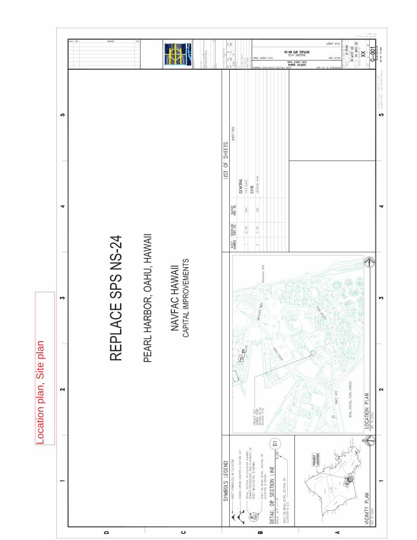
Loca
tion
plan
,Site
plan
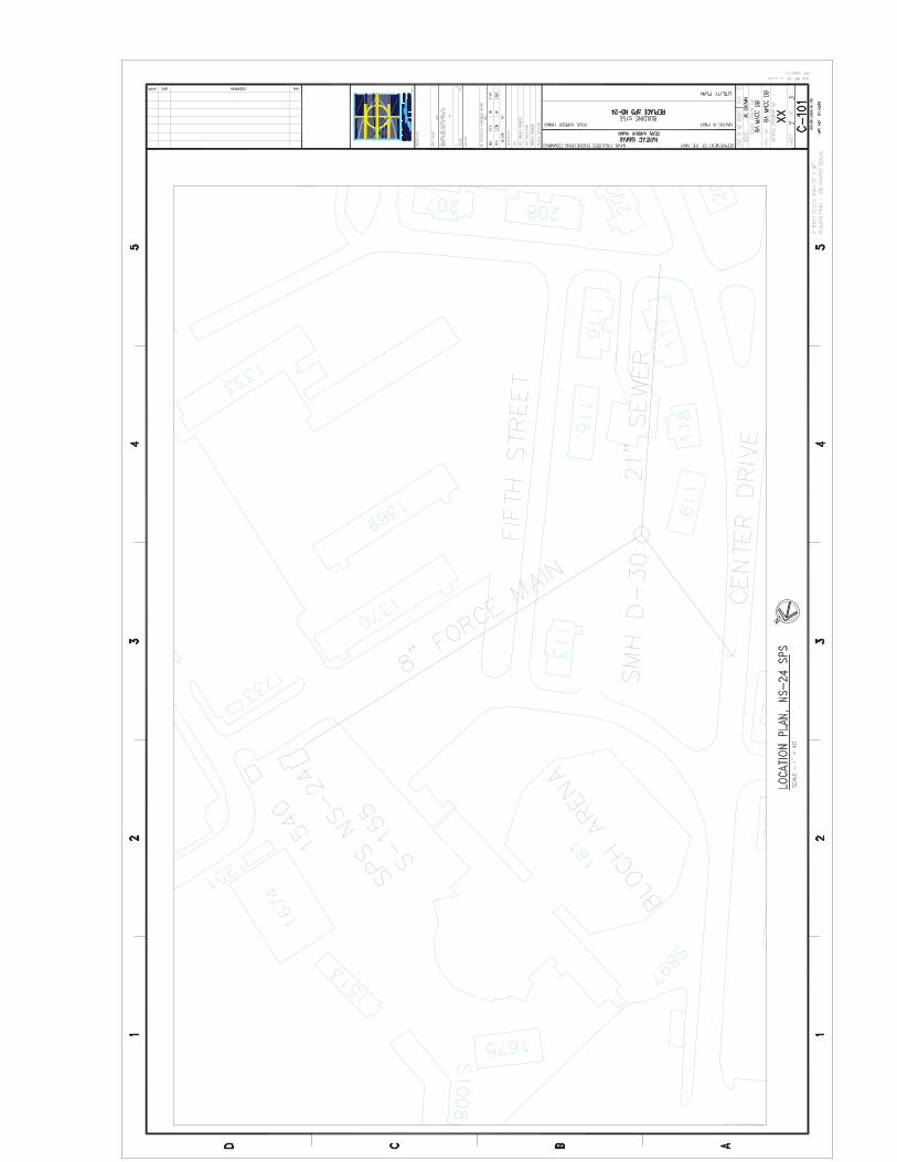
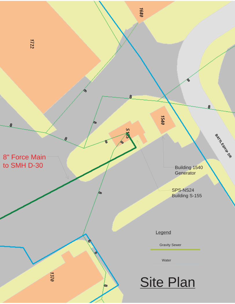
8" Force Mainto SMH D-30
Gravity Sewer
Water
SPS-NS24Building S-155
Building 1540Generator
Site Plan
Legend

STATION NUMBER: NS-24BUILDING #: S155LOCATION: NAVSTA, OLD CPO
TYPE OF STATION: DRY PRIME, CENTRIFUGALS
NUMBER OF PUMPS----2 GPM-------------------------- 800 @ 43' EMERG GEN---------------YES, 75 KW EMERG HIGH RISE------NA TYPE CONTROLS--------X-ducer, PLC SCADA SYSTEM------------------
DATE:11/24/1999 INITIATE NEW HISTORY FILE12/17/1999 STARTED DATA INPUT FOR PRIV. EFFORT.dlc
HISTORY DATA
NS-024 information

FACILITY DATA
STATION #_________________________ NS-24
BUILDING #_________________________ S155
LOCATION__________________________ NAVAL STATION
TYPE STATION (CAN, DRY PIT, ETC) DRY PRIME ,CENTRIFUGAL PUMP
NO. FLOORS 1
NO. PUMPS 3, 2 PRIMARY PUMPS AND 1 EMRG. L/NOSE
STATION DESIGN CAPACITY (GPM's) 800
PERIMITER FENCE DIMENSIONS FENCE
STRUCTURE DIMENSIONS 20' BY 30'
PUMPS TO? (LOCATION) M/HOLE BY HALE MOKU, GRAVITY TO SY01
COMMENTS:
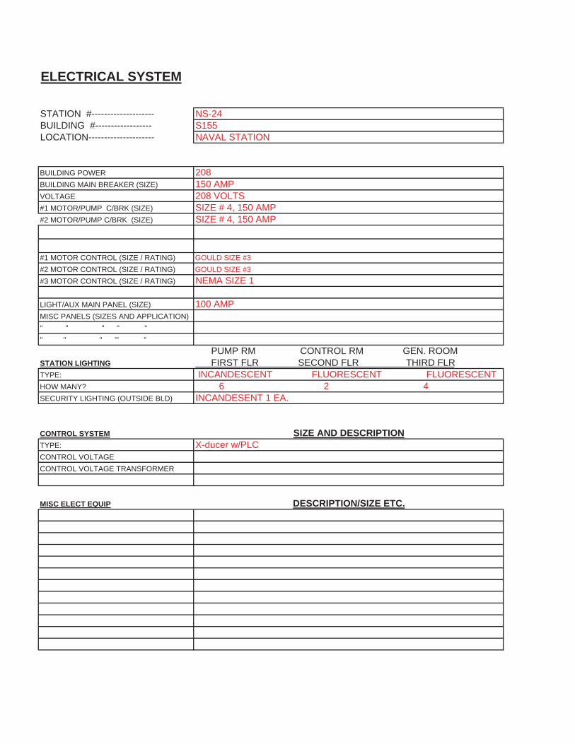
ELECTRICAL SYSTEM
STATION #-------------------- NS-24BUILDING #------------------ S155LOCATION--------------------- NAVAL STATION
BUILDING POWER 208BUILDING MAIN BREAKER (SIZE) 150 AMPVOLTAGE 208 VOLTS#1 MOTOR/PUMP C/BRK (SIZE) SIZE # 4, 150 AMP#2 MOTOR/PUMP C/BRK (SIZE) SIZE # 4, 150 AMP
#1 MOTOR CONTROL (SIZE / RATING) GOULD SIZE #3#2 MOTOR CONTROL (SIZE / RATING) GOULD SIZE #3#3 MOTOR CONTROL (SIZE / RATING) NEMA SIZE 1
LIGHT/AUX MAIN PANEL (SIZE) 100 AMPMISC PANELS (SIZES AND APPLICATION)" " " " "" " " '" "
PUMP RM CONTROL RM GEN. ROOMSTATION LIGHTING FIRST FLR SECOND FLR THIRD FLRTYPE: INCANDESCENT FLUORESCENT FLUORESCENTHOW MANY? 6 2 4SECURITY LIGHTING (OUTSIDE BLD) INCANDESENT 1 EA.
CONTROL SYSTEM SIZE AND DESCRIPTIONTYPE: X-ducer w/PLCCONTROL VOLTAGECONTROL VOLTAGE TRANSFORMER
MISC ELECT EQUIP DESCRIPTION/SIZE ETC.
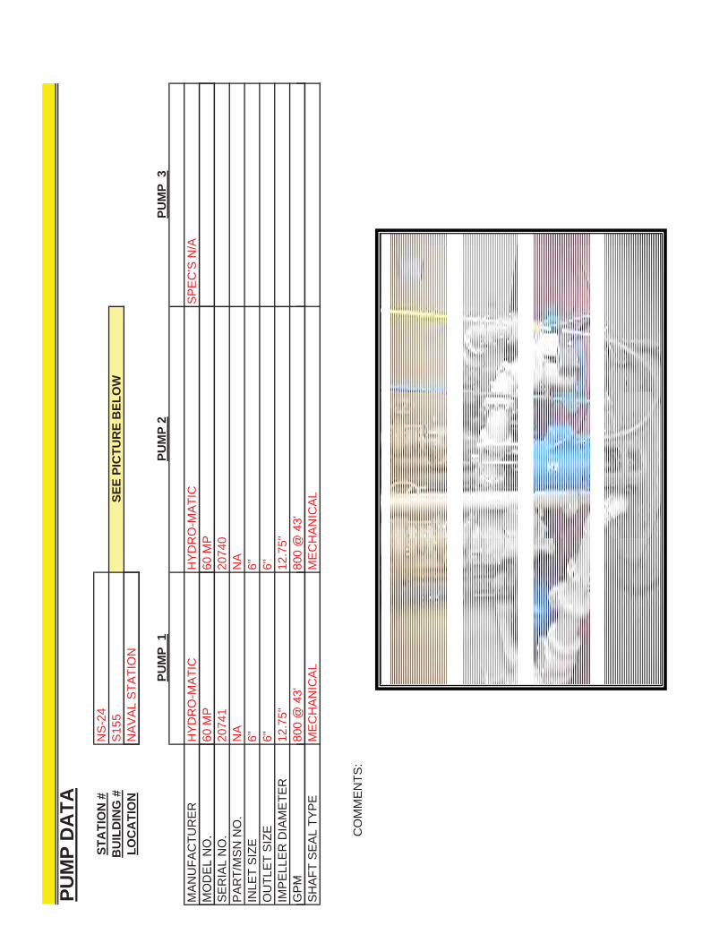
PUM
P D
ATA
STA
TIO
N #
NS
-24
BU
ILD
ING
#S
155
SEE
PIC
TUR
E B
ELO
WLO
CA
TIO
NN
AV
AL
STA
TIO
NLO
CA
TIO
NN
AV
AL
STA
TIO
N
PUM
P 1
PUM
P 2
PUM
P 3
MA
NU
FAC
TUR
ER
HY
DR
O-M
ATI
CH
YD
RO
-MA
TIC
SP
EC
'S N
/AM
OD
EL
NO
.60
MP
60 M
PM
OD
EL
NO
.60
MP
60M
PS
ER
IAL
NO
.20
741
2074
0P
AR
T/M
SN
NO
.N
AN
AIN
LET
SIZ
E6"
6"O
UTL
ET
SIZ
E6"
6"IM
PE
LLE
R D
IAM
ETE
R12
.75"
12.7
5"G
PM
800
@43
'80
0@
43'
GP
M80
0@
4380
0@
43S
HA
FT S
EA
L TY
PE
ME
CH
AN
ICA
LM
EC
HA
NIC
AL
CO
MM
ENTS
:

PIPING DATASTATION #____________________________NS-24BUILDING #____________________________S155LOCATION_____________________________NAVAL STATION
SEE PICTURES BELOW
INLET NO. 1 NO. 2 NO. 3PIPE SIZE 6" 6" 4"VALVE SIZE AND TYPE NO VALVE NO VALVE NAFACE TO FACE DIMENSIONS NA NA NANO. BOLTS AND SIZE NA NA NA
OUTLETPIPE SIZE 6" 6" 4X6"PIPE SIZE 6 6 4X6SHUT-OFF VALVE, TYPE AND SIZE 6" PLUG, DEZURIC 6" PLUG, DEZURIC 6" GATEFACE TO FACE DIMENSIONS 10 1/2" 10 1/2" 10 3/4"NO. BOLTS AND SIZE 8/ 3/4" BY 3 1/4" 8/ 3/4" BY 3 1/4" 8/ 3/4" BY 3 1/4"CHECK VALVE 6" 6" 6"FACE TO FACE DIMENSIONS 16 1/2 " 16 1/2 " 14" NO. BOLTS AND SIZE 8/ 3/4" BY 3 1/4" 8/ 3/4" BY 3 1/4" 8/ 3/4" BY 3 1/4"
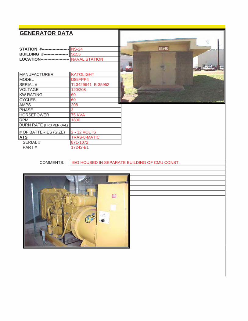
GENERATOR DATA
STATION #-------------------- NS-24BUILDING #------------------ S155LOCATION--------------------- NAVAL STATION
MANUFACTURER KATOLIGHTMODEL D85FPP4SERIAL # TL3429641 B-35952VOLTAGE 120/208KW RATING 60CYCLES 60CYCLES 60AMPS 208PHASE 3HORSEPOWER 75 KVARPM 1800BURN RATE (HRS PER GAL)
# OF BATTERIES (SIZE) 2 - 12 VOLTSATS TRAS 0 MATICATS TRAS-0-MATIC SERIAL # 871-1072 PART # 17242-B1
COMMENTS: E/G HOUSED IN SEPARATE BUILDING OF CMU CONST.
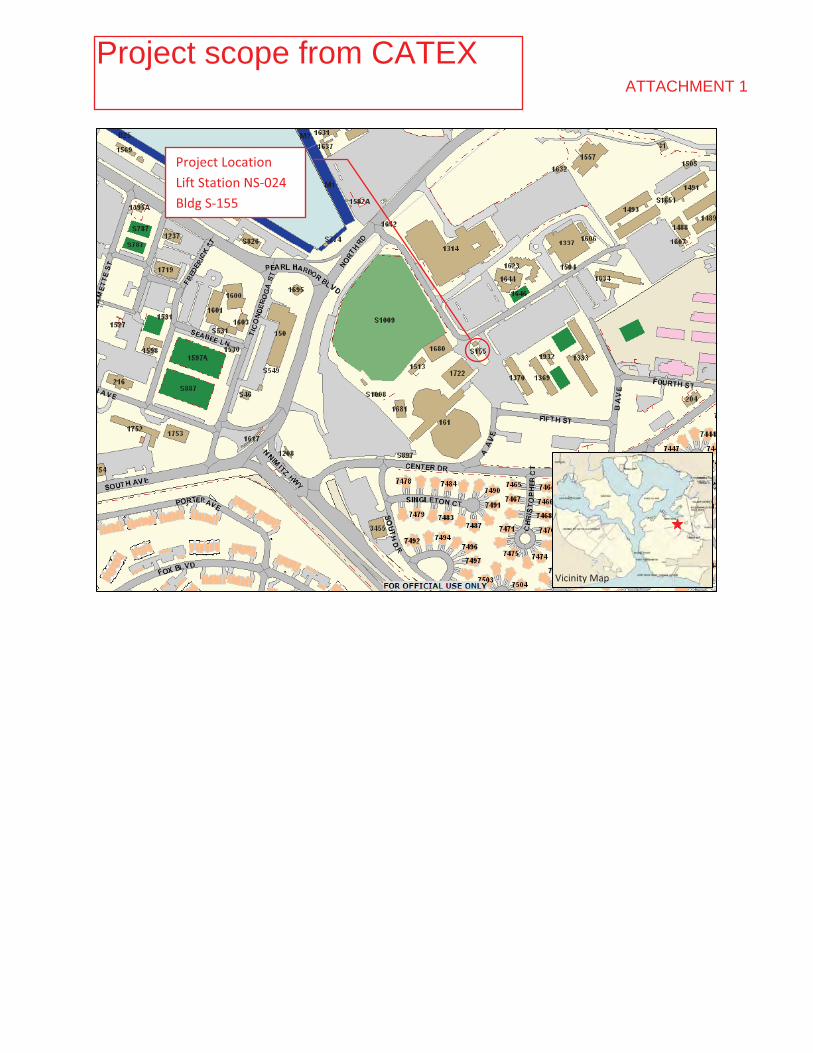
�
�
Vicinity�Map�
Project�Location��Lift�Station�NS�024������Bldg�S�155�
ATTACHMENT 1
Project scope from CATEX

�
�
�
�
ATTACHMENT 1
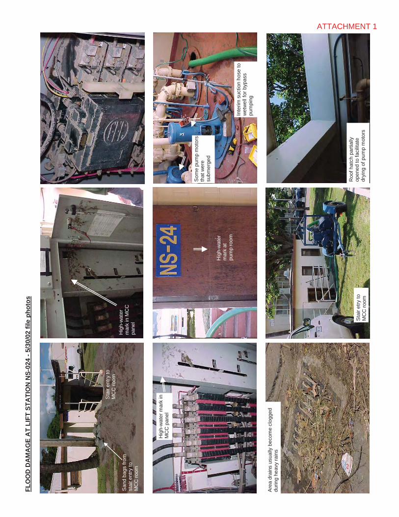
FLO
OD
DA
MA
GE
AT
LIFT
STA
TIO
N N
S-02
4 - 5
/30/
02 fi
le p
hoto
s
San
d ba
gs fr
om
stai
r ent
ry to
M
CC
room
Hig
h-w
ater
m
ark
in M
CC
pa
nel
Hi
ht
Hig
h-w
ater
mar
k in
M
CC
pan
el
Som
e pu
mp
mot
ors
that
wer
e su
bmer
ged
Sta
ir en
try to
M
CC
room
San
d ba
gs fr
om
stai
r ent
ry to
M
CC
room
Hig
h-w
ater
m
ark
in M
CC
pa
nel
Hig
h-w
ater
m
ark
at
pum
p ro
om
Hig
h-w
ater
mar
k in
M
CC
pan
el
Som
e pu
mp
mot
ors
that
wer
e su
bmer
ged
Are
a dr
ains
usu
ally
bec
ome
clog
ged
durin
g he
avy
rain
s
Sta
ir en
try to
M
CC
room
Sta
ir et
ry to
M
CC
room
Roo
f hat
ch p
artia
lly
open
ed to
faci
litat
e dr
ying
of p
ump
mot
ors
Inte
rim s
uctio
n ho
se to
w
etw
ell f
or b
ypas
s pu
mpi
ng
ATTACHMENT 1
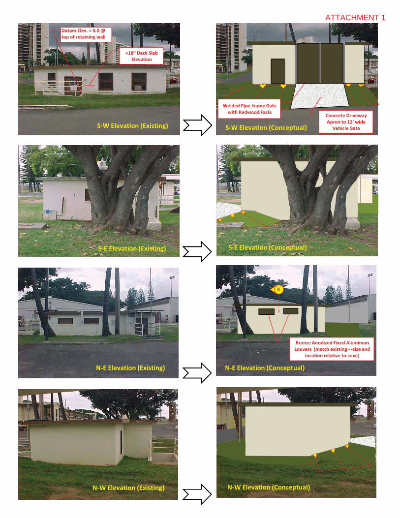
S�W�Elevation (Existing) S�W�Elevation (Conceptual)
S�E�Elevation (Existing) S�E�Elevation (Conceptual)
Datum�Elev.�=�0.0�@�top�of�retaining�wall
+18"�Deck�Slab�Elevation
Concrete�Driveway�Apron�to�12'�wide
Vehicle�Gate
Welded Pipe�frame�Gate��with�Redwood�Facia
S�W�Elevation (Existing) S�W�Elevation (Conceptual)
S�E�Elevation (Existing) S�E�Elevation (Conceptual)
N�E�Elevation (Existing) N�E�Elevation (Conceptual)
N�W�Elevation (Existing) N�W�Elevation (Conceptual)
Datum�Elev.�=�0.0�@�top�of�retaining�wall
+18"�Deck�Slab�Elevation
Concrete�Driveway�Apron�to�12'�wide
Vehicle�Gate
A
Bronze�Anodized Fixed�Aluminum�Louvers��(match�existing�� �size�and�
location�relative�to�eave)
Welded Pipe�frame�Gate��with�Redwood�Facia
ATTACHMENT 1
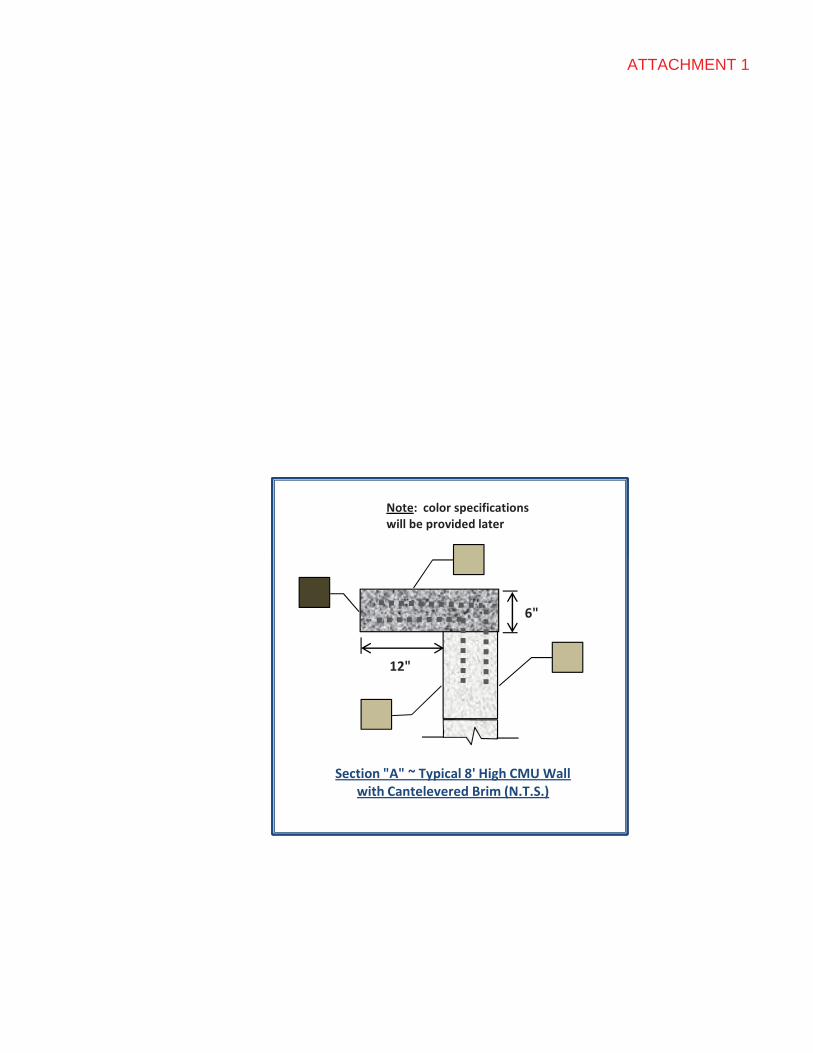
Note:��color specifications�will�be�provided�later
Section�"A"�~�Typical�8'�High�CMU�Wall�with�Cantelevered�Brim�(N.T.S.)
12"
6"
Note:��color specifications�will�be�provided�later
Section�"A"�~�Typical�8'�High�CMU�Wall�with�Cantelevered�Brim�(N.T.S.)
12"
6"
Note:��color specifications�will�be�provided�later
ATTACHMENT 1
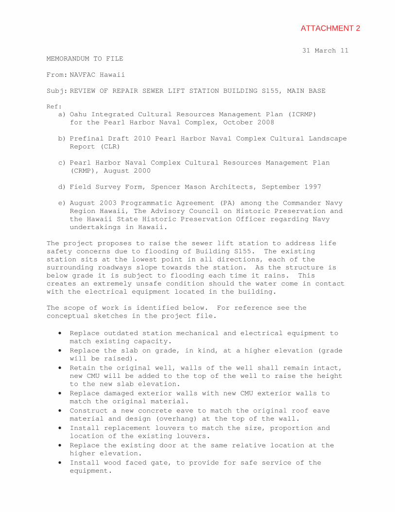
31 March 11 MEMORANDUM TO FILE
From: NAVFAC Hawaii
Subj: REVIEW OF REPAIR SEWER LIFT STATION BUILDING S155, MAIN BASE
Ref: a) Oahu Integrated Cultural Resources Management Plan (ICRMP)
for the Pearl Harbor Naval Complex, October 2008
b) Prefinal Draft 2010 Pearl Harbor Naval Complex Cultural Landscape Report (CLR)
c) Pearl Harbor Naval Complex Cultural Resources Management Plan (CRMP), August 2000
d) Field Survey Form, Spencer Mason Architects, September 1997
e) August 2003 Programmatic Agreement (PA) among the Commander Navy Region Hawaii, The Advisory Council on Historic Preservation and the Hawaii State Historic Preservation Officer regarding Navy undertakings in Hawaii.
The project proposes to raise the sewer lift station to address life safety concerns due to flooding of Building S155. The existing station sits at the lowest point in all directions, each of the surrounding roadways slope towards the station. As the structure is below grade it is subject to flooding each time it rains. This creates an extremely unsafe condition should the water come in contact with the electrical equipment located in the building.
The scope of work is identified below. For reference see the conceptual sketches in the project file.
� Replace outdated station mechanical and electrical equipment to match existing capacity.
� Replace the slab on grade, in kind, at a higher elevation (grade will be raised).
� Retain the original well, walls of the well shall remain intact, new CMU will be added to the top of the well to raise the height to the new slab elevation.
� Replace damaged exterior walls with new CMU exterior walls to match the original material.
� Construct a new concrete eave to match the original roof eave material and design (overhang) at the top of the wall.
� Install replacement louvers to match the size, proportion and location of the existing louvers.
� Replace the existing door at the same relative location at the higher elevation.
� Install wood faced gate, to provide for safe service of the equipment.
ATTACHMENT 2
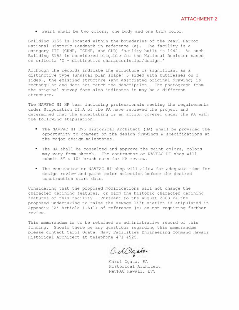
� Paint shall be two colors, one body and one trim color.
Building S155 is located within the boundaries of the Pearl Harbor National Historic Landmark in reference (a). The facility is a category III (CRMP, ICRMP, and CLR) facility built in 1942. As such Building S155 is considered eligible for the National Resister based on criteria ‘C – distinctive characteristics/design.’
Although the records indicate the structure is significant as a distinctive type (unusual plan shape; 5-sided with buttresses on 3 sides), the existing structure (and associated original drawing) is rectangular and does not match the description. The photograph from the original survey form also indicates it may be a different structure.
The NAVFAC HI HP team including professionals meeting the requirements under Stipulation II.A of the PA have reviewed the project and determined that the undertaking is an action covered under the PA with the following stipulation:
� The NAVFAC HI EV5 Historical Architect (HA) shall be provided the opportunity to comment on the design drawings & specifications at the major design milestones.
� The HA shall be consulted and approve the paint colors, colors may vary from sketch. The contractor or NAVFAC HI shop will submit 8” x 10” brush outs for HA review.
� The contractor or NAVFAC HI shop will allow for adequate time for design review and paint color selection before the desired construction start date.
Considering that the proposed modifications will not change the character defining features, or harm the historic character defining features of this facility – Pursuant to the August 2003 PA the proposed undertaking to raise the sewage lift station is stipulated in Appendix ‘A’ Article I.A(1) of reference (e) as not requiring further review.
This memorandum is to be retained as administrative record of this finding. Should there be any questions regarding this memorandum please contact Carol Ogata, Navy Facilities Engineering Command Hawaii Historical Architect at telephone 471-4525.
Carol Ogata, RA Historical Architect NAVFAC Hawaii, EV5
ATTACHMENT 2

2�w
ay�D
eck�
Slab
,�+18
"�ab
ove�
surr
ound
ing�
eart
h�gr
ades
Day
light
�to�
Asp
halt�
Pave
men
t,�S
�E�
elev
atio
n
Build
�up�
wet
ell�w
alls
�to�
high
er�e
leva
tion
Rou
ghpr
ojec
tsco
pe-2
shee
ts

Dem
o/fil
l
Dem
o/fil
l
Prov
ide�
pede
strian
�gate
Prov
ide�ov
erha
ng�ro
ofab
ove�ne
w�deck�
mou
nted
�NEM
A�4�X�
MCC
�line
�up
Dup
lexde
ck�
Emer.�pum
p�by
pass�
riser�a
ssem
bly
Dup
lex�de
ck�
mou
nted
,direct�cou
pled
,�self�prim
ing�
vacuum
�pum
ps
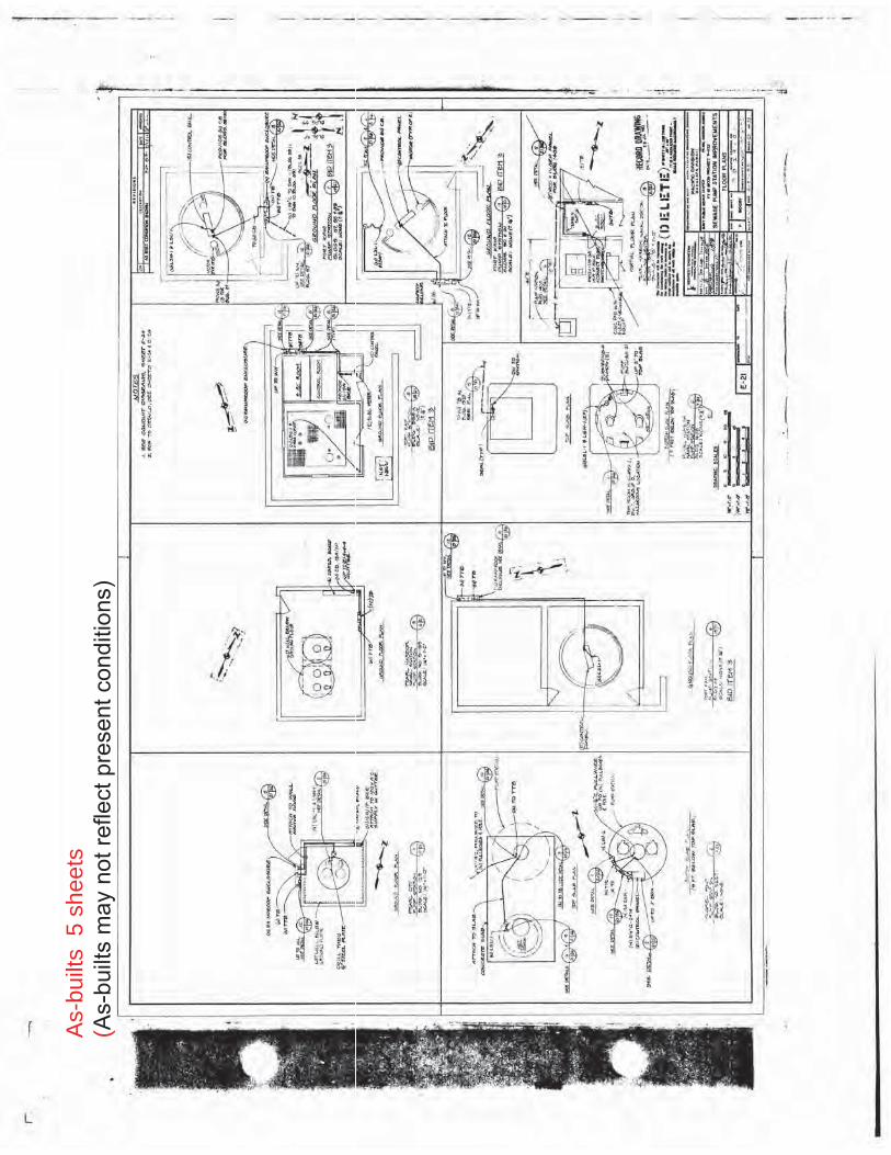
As-
built
s5
shee
ts(A
s-bu
ilts
may
not
refle
ct p
rese
nt c
ondi
tions
)
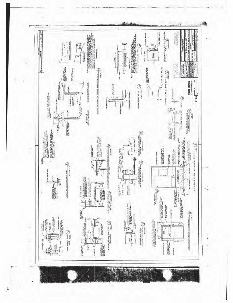
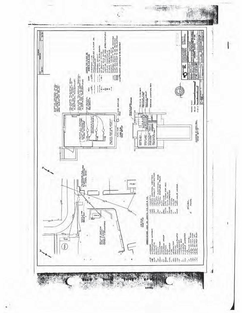
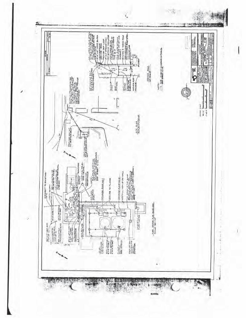
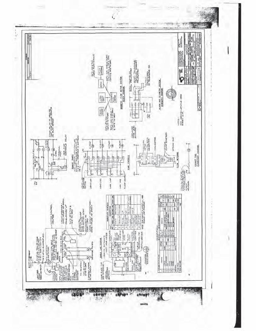
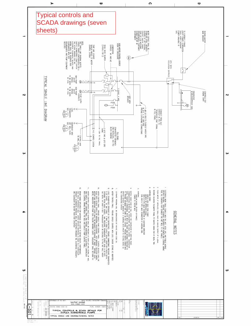
Typical controls andSCADA drawings (sevensheets)
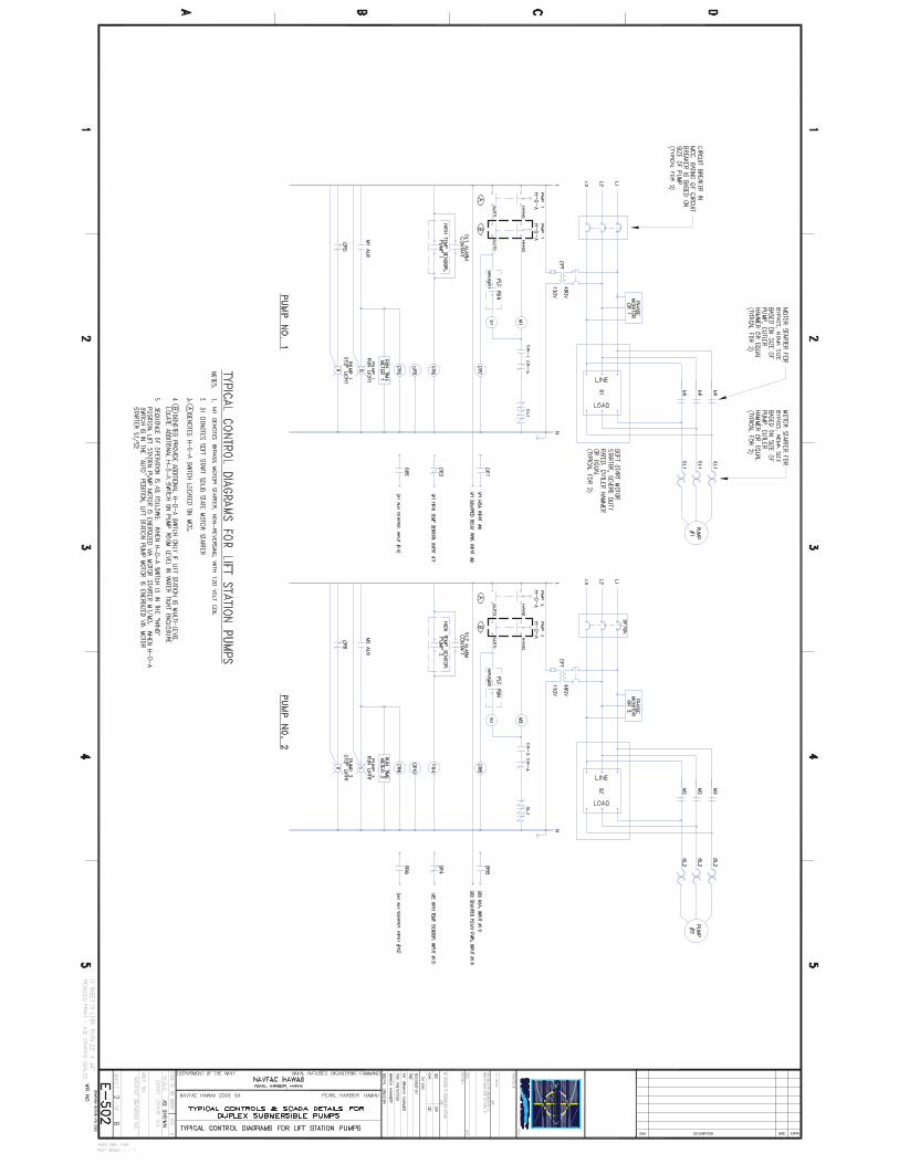

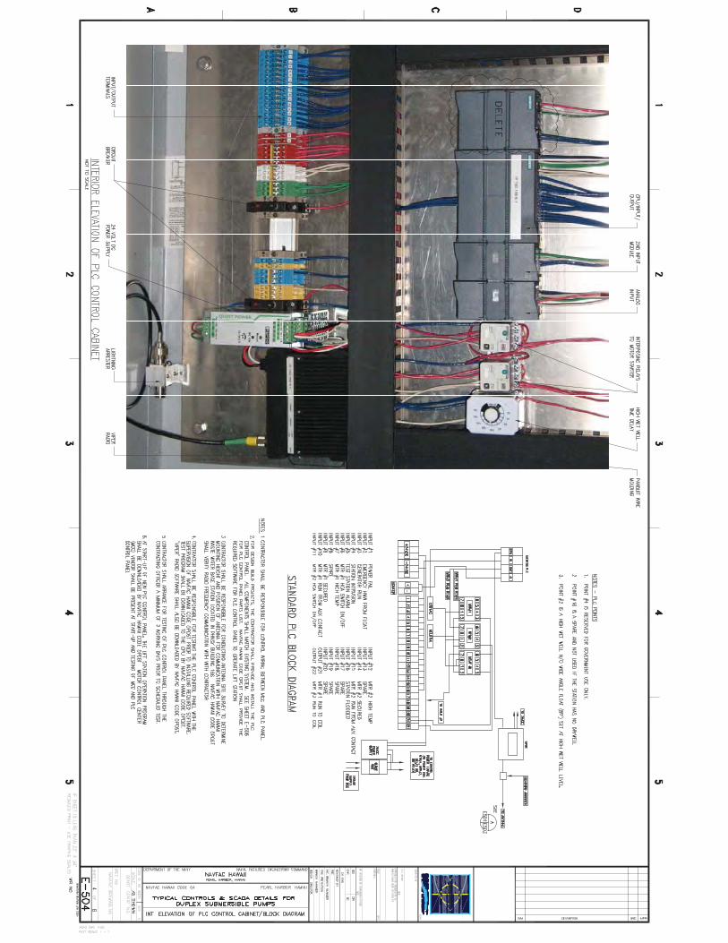
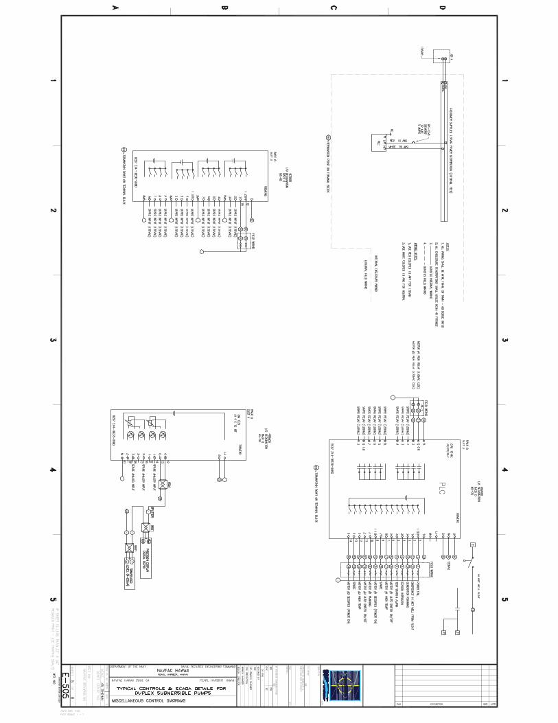
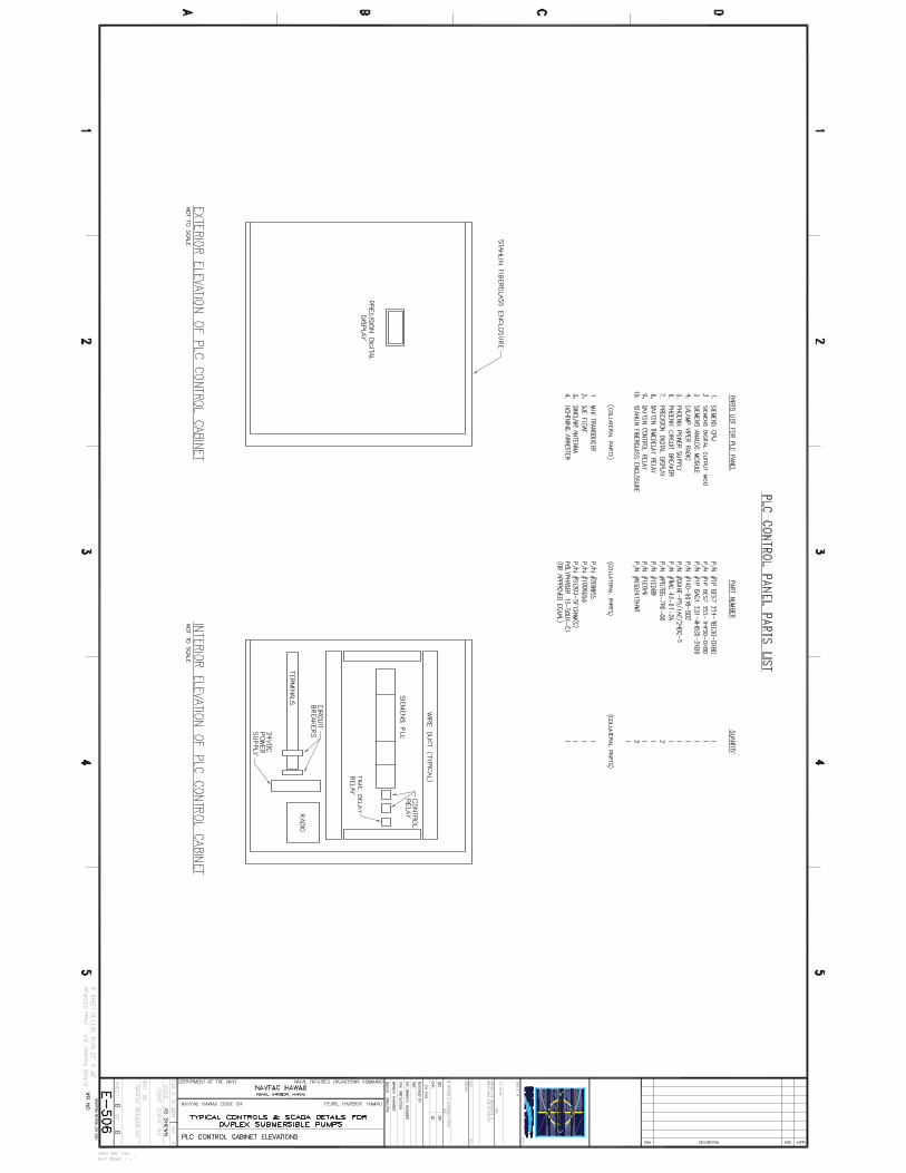

'É!
!
!
!
!!
!
)#
)#
)#
)#)#
)#
)#)# )#
)#
#
#
#
å
å
å
å
å
!
!
!!
!
!
!
! !
!
!
!
!
!
!
!
!
!
!
!
!
!
!
!
!
!
!
!
#
#
#
NH
12A
4
NH
1 2A
3
NH
6D
NH
6EN
H6F
MIA
MIC
I STA
H8
STA
H11
ST H3
STA
H6
STA
H7
STA
H21
STA
T3
STA
T1
STA
T 6
STA
T5
STA
H37
3-25
KVA
3-25
KVA
25 KVA
H33
A
H33
B
H33
C
H63
H32
B
H10
2H
101
H26
A
H
H33
H3
H32
A
H32
H32
D
H32
B1
H31
H32
C
H49
H31
A
H32
B
H49
A
H50
A
H
H32
C
H34
D
H11
6
H32
F3
H11
7
H11
8
H11
9
H11
312 4
H11
5
0
161
1314
1722
1644
1680
1 370
1681
1513
S89
7
S15
5
1009
1540
S10
08
1630
1612
1582 S
1137
1676
1915
101
111
11711
3
103
115
125
00
303
3 00
105
119
121
127
2
123
301
10910
7
BATA
AVE
SINGLETON CT
RC
T
CENTER DR
NORTH RD
R
M1
S774
H33
B1
BATT
LES
HIP
DR
S100
9
1646
SK
E-1
PA
RTI
AL
ELE
CTR
ICA
LS
ITE
PLA
NN
OT
TOS
CA
LE