navy electricity and electronics training series€¦ · module 4-electrical conductors, wiring...
TRANSCRIPT

UNCLASSIFIED
UNCLASSIFIED
Notice: NETPDTC is no longer responsible for the content accuracy of the NRTCs. For content issues, contact the servicing Center of Excellence: Center for Surface Combat Systems; (540) 284-1061 or DSN: 234. For course registration, issues, or login issues contact the NRTC Helpdesk at: 1-877-264-8583 DSN: 922-1511 or Email: [email protected] DISTRIBUTION STATEMENT A: Approved for public release; distribution is unlimited.
NONRESIDENT TRAINING COURSE
May 2013
Navy Electricity and Electronics Training
Series
Module 4—Electrical Conductors, Wiring Techniques, and Schematic Reading
NAVEDTRA 14176A
S/N 0504LP1122345

UNCLASSIFIED
UNCLASSIFIED
DISTRIBUTION STATEMENT A: Approved for public release; distribution is unlimited.
Although the words “he,” “him,” and “his” are used sparingly in this course to enhance communication, they are not intended to be gender driven or to affront or discriminate against anyone.

UNCLASSIFIED
i UNCLASSIFIED
PREFACE
By enrolling in this self-study course, you have demonstrated a desire to improve yourself and the Navy. Remember, however, this self-study course is only one part of the total Navy training program. Practical experience, schools, selected reading, and your desire to succeed are also necessary to successfully round out a fully meaningful training program. THE COURSE: This self-study course is organized into subject matter areas, each containing learning objectives to help you determine what you should learn along with text and illustrations to help you understand the information. The subject matter reflects day-to-day requirements and experiences of personnel in the rating or skill area. It also reflects guidance provided by Enlisted Community Managers (ECMs) and other senior personnel, technical references, instructions, etc., and either the occupational or naval standards, which are listed in the Manual of Navy Enlisted Manpower Personnel Classifications and Occupational Standards, NAVPERS 18068. THE QUESTIONS: The questions that appear in this course are designed to help you understand the material in the text. VALUE: In completing this course, you will improve your military and professional knowledge. Importantly, it can also help you study for the Navy-wide advancement in rate examination. If you are studying and discover a reference in the text to another publication for further information, look it up.
2013 Edition
Published by Center for Surface Combat Systems (CSCS)
NAVSUP Logistics Tracking Number 0504-LP-112-2345

UNCLASSIFIED
ii UNCLASSIFIED
Sailor’s Creed
“I am a United States Sailor. I will support and defend the Constitution of the United States of America and I will obey the orders of those appointed over me. I represent the fighting spirit of the Navy and those who have gone before me to defend freedom and democracy around the world. I proudly serve my country’s Navy combat team with honor, courage and commitment. I am committed to excellence and the fair treatment of all.”

UNCLASSIFIED
iii UNCLASSIFIED
TABLE OF CONTENTS CHAPTER PAGE 1 Electrical Conductors........................................................................... 1-1 2 Wiring Techniques…………................................................................ 2-1 3 Schematic Reading............................................................................... 3-1 APPENDIX A Glossary................................................................................................ A-1 B Electrical and Electronic Symbols........................................................ B-1 C References…………............................................................................. C-1
Course Assignments follow Appendix C

UNCLASSIFIED
iv UNCLASSIFIED
NAVY ELECTRICITY AND ELECTRONICS TRAINING SERIES
The Navy Electricity and Electronics Training Series (NEETS) was developed for use by personnel in many electrical and electronic-related Navy ratings. Written by, and with the advice of, senior technicians in these ratings, this series provides beginners with fundamental electrical and electronic concepts through self-study. The presentation of this series is not oriented to any specific rating structure, but is divided into modules containing related information organized into traditional paths of instruction. The series is designed to give small amounts of information that can be easily digested before advancing further into the more complex material. For a student just becoming acquainted with electricity or electronics, it is highly recommended that the modules be studied in their suggested sequence. Considerable emphasis has been placed on illustrations to provide a maximum amount of information. In some instances, knowledge of basic algebra may be required. Course descriptions and ordering information may be found at https://www.netc.navy.mil then click on the Programs tab, then select the Nonresident Training Courses from the list. Throughout the text of this course and while using technical manuals associated with the equipment you will be working on, you will find the below notations at the end of some paragraphs. The notations are used to emphasize that safety hazards exist and care must be taken or observed.
WARNING AN OPERATING PROCEDURE, PRACTICE, OR CONDITION, ETC., WHICH MAY RESULT IN INJURY OR DEATH IF NOT CAREFULLY OBSERVED OR FOLLOWED.
CAUTION AN OPERATING PROCEDURE, PRACTICE, OR CONDITION, ETC., WHICH MAY RESULT IN DAMAGE TO EQUIPMENT IF NOT CAREFULLY OBSERVED OR FOLLOWED.
NOTE An operating procedure, practice, or condition, etc., which is essential to emphasize.

UNCLASSIFIED
v UNCLASSIFIED
STUDENT FEEDBACK AND QUESTIONS We value your suggestions, questions, and criticisms on our courses. If you would like to communicate with us regarding this course, we encourage you, if possible, to use e-mail or to post your comments on the Community of Practice (COP) page located at https://wwwa.nko.navy.mil/portal/home/. If you write or fax, please use a copy of the Student Comment form that follows this page.
For subject matter questions: E-mail: [email protected] Phone: Comm: 540-284-1061 DSN: 234-4639 Address: COMMANDING OFFICER Center for Surface Combat Systems 5395 First St Dahlgren, VA 22448-5200

UNCLASSIFIED
vi UNCLASSIFIED
Student Comments
Course Title: NEETS Module 4-Electrical Conductors, Wiring Techniques, and Schematic Reading NAVEDTRA: 14176A Date: ____________ We need some information about you: Rate/Rank and Name: _____________ Command/Unit: _________________________ Street Address: ________________ City: _____________ State/FPO: _____ Zip _____ Your comments, suggestions, etc.:
Privacy Act Statement: Under authority of Title 5, USC 301, information regarding your military status is requested in processing your comments and in preparing a reply. This information will not be divulged without written authorization to anyone other than those within DOD for official use in determining performance.

UNCLASSIFIED
vii UNCLASSIFIED
This page left intentionally blank.

Module 4-Electrical Conductors, Wiring Techniques, and Schematic Reading UNCLASSIFIED
1-1 UNCLASSIFIED
1 ELECTRICAL CONDUCTORS
LEARNING OBJECTIVES Upon completing this chapter, you should be able to: 1. Recall the definitions of unit size, mil-foot, square mil, and circular mil and the
mathematical equations and calculations for each. 2. Define specific resistance and recall the three factors used to calculate it in ohms. 3. Describe the proper use of the American Wire Gauge when making wire
measurements. 4. Recall the factors required in selecting proper size wire. 5. State the advantages and disadvantages of copper or aluminum as conductors. 6. Define insulation resistance and dielectric strength including how the dielectric
strength of an insulator is determined. 7. Identify the safety precautions to be taken when working with insulating materials. 8. Recall the most common insulators used for extremely high voltages. 9. State the type of conductor protection normally used for shipboard wiring. 10. Recall the design and use of coaxial cable. 1.1 INTRODUCTION TO ELECTRICAL CONDUCTORS
In the previous modules of this training series, you have learned about various circuit components. These components provide the majority of the operating characteristics of any electrical circuit. They are useless, however, if they are not connected together. Conductors are the means used to tie these components together. Many factors determine the type of electrical conductor used to connect components. Some of these factors are the physical size of the conductor, its composition, and its electrical characteristics. Other factors that can determine the choice of a conductor are the weight, the cost, and the environment where the conductor will be used.

Module 4-Electrical Conductors, Wiring Techniques, and Schematic Reading UNCLASSIFIED
1-2 UNCLASSIFIED
1.2 CONDUCTOR SIZES
To compare the resistance and size of one conductor with that of another, we need to establish a standard or unit size. A convenient unit of measurement of the diameter of a conductor is the mil (0.001, or one-thousandth of an inch). A convenient unit of conductor length is the foot. The standard unit of size in most cases is the MIL-FOOT. A wire will have a unit size if it has a diameter of 1 mil and a length of 1 foot. 1.2.1 Square Mil
The square mil is a unit of measurement used to determine the cross-sectional area of a square or rectangular conductor (views A and B of figure 1-1). A square mil is defined as the area of a square, the sides of which are each 1 mil. To obtain the cross-sectional area of a square conductor, multiply the dimension of any side of the square by itself. For example, assume that you have a square conductor with a side dimension of 3 mils. Multiply 3 mils by itself (3 mils ⋅ 3 mils). This gives you a cross-sectional area of 9 square mils.
Figure 1-1 Cross-sectional areas of conductors

Module 4-Electrical Conductors, Wiring Techniques, and Schematic Reading UNCLASSIFIED
1-3 UNCLASSIFIED
Q1. State the reason for the establishment of a "unit size" for conductors.
Q2. Calculate the diameter in MILS of a conductor that has a diameter of 0.375 inch.
Q3. Define a mil-foot.
To determine the cross-sectional area of a rectangular conductor, multiply the length times the width of the end face of the conductor (side is expressed in mils). For example, assume that one side of the rectangular cross-sectional area is 6 mils and the other side is 3 mils. Multiply 6 mils ⋅ 3 mils, which equals 18 square mils. Here is another example. Assume that a conductor is 3/8 inch thick and 4 inches wide. The 3/8 inch can be expressed in decimal form as 0.375 inch. Since 1 mil equals 0.001 inch, the thickness of the conductor will be 0.001 ⋅ 0.375, or 375 mils. Since the width is 4 inches and there are 1,000 mils per inch, the width will be 4 ⋅ 1,000, or 4,000 mils. To determine the cross-sectional area, multiply the length by the width; or 375 mils ⋅ 4,000 mils. The area will be 1,500,000 square mils. Q4. Define a square mil as it relates to a square conductor.

Module 4-Electrical Conductors, Wiring Techniques, and Schematic Reading UNCLASSIFIED
1-4 UNCLASSIFIED
1.2.2 CIRCULAR MIL
The circular mil is the standard unit of measurement of a round wire cross-sectional area (view C of figure 1-1). This unit of measurement is found in American and English wire tables. The diameter of a round conductor (wire) used to conduct electricity may be only a fraction of an inch. Therefore, it is convenient to express this diameter in mils to avoid using decimals. For example, the diameter of a wire is expressed as 25 mils instead of 0.025 inch. A circular mil is the area of a circle having a diameter of 1 mil, as shown in view B of figure 1-2. The area in circular mils of a round conductor is obtained by squaring the diameter, measured in mils. Thus, a wire having a diameter of 25 mils has an area of 252, or 625 circular mils. To determine the number of square mils in the same conductor, apply the conventional formula for determining the area of a circle (A = πr2). In this formula, A (area) is the unknown and is equal to the cross-sectional area in square mils, π is the constant 3.14, and r is the radius of the circle, or half the diameter (D). Through substitution, A = 3.14, and (12.5)2; therefore, 3.14 ⋅ 156.25 = 490.625 square mils. The cross-sectional area of the wire has 625 circular mils but only 490.625 square mils. Therefore, a circular mil represents a smaller unit of area than the square mil.
Figure 1-2 A comparison of circular and square mils

Module 4-Electrical Conductors, Wiring Techniques, and Schematic Reading UNCLASSIFIED
1-5 UNCLASSIFIED
If a wire has a cross-sectional diameter of 1 mil, by definition, the circular mil area (CMA) is A = D2, or A = 12, or A = 1 circular mil. To determine the square mil area of the same wire, apply the formula A = πr2; therefore, A = 3.14 x (.5)2 (.5 representing half the diameter). When A = 3.14 x 25, A = .7854 square mil. From this, it can be concluded that 1 circular mil is equal to .7854 square mil. This becomes important when square (view A of figure 1-2) and round (view B) conductors are compared as in view C of figure 1-2. When the square mil area is given, divide the area by 0.7854 to determine the circular mil area, or CMA. When the CMA is given, multiply the area by 0.7854 to determine the square mil area. For example, Problem: A 12-gauge wire has a diameter of 80.81 mils. What is (1) its area in circular mils and (2) its area in square mils? Solution: (1) A = D2 = 80.812 = 6,530 circular mils (2) A = 0.7854 x 6,530 = 5,128.7 square mils Problem: A rectangular conductor is 1.5 inches wide and 0.25 inch thick. What is (1) its area in square mils and (2) in circular mils? What size of round conductor is necessary to carry the same current as the rectangular bar? Solution: (1) 1.5 inches = 1.5 inches x 1,000 mils per inch = 1,500 mils 0.25 inch = 0.25 inch x 1,000 mils per inch = 250 mils A = 1,500 x 250 = 375,000 square mils (2) To carry the same current, the cross-sectional area of the round conductor must be equal. There are more circular mils than square mils in this area. Therefore,
A = 375,0000.7854
= 477,000 circular mils

Module 4-Electrical Conductors, Wiring Techniques, and Schematic Reading UNCLASSIFIED
1-6 UNCLASSIFIED
A wire in its usual form is a single slender rod or filament of drawn metal. In large sizes, wire becomes difficult to handle. To increase its flexibility, it is stranded. Strands are usually single wires twisted together in sufficient numbers to make up the necessary cross-sectional area of the cable. The total area of stranded wire in circular mils is determined by multiplying the area in circular mils of one strand by the number of strands in the cable. Q5. Define a circular mil.
Q6. What is the circular mil area of a 19-strand conductor if each strand is 0.004 inch?
1.2.3 Circular-Mil-Foot
A circular-mil-foot (figure 1-3) is a unit of volume. It is a unit conductor 1foot in length and has a cross-sectional area of 1 circular mil. Because it is a unit conductor, the circular-mil-foot is useful in making comparisons between wires consisting of different metals. For example, a basis of comparison of the RESISTIVITY (to be discussed shortly) of various substances may be made by determining the resistance of a circular-mil-foot of each of the substances. In working with square or rectangular conductors, such as ammeter shunts and bus bars, you may sometimes find it more convenient to use a different unit volume. A bus bar is a heavy copper strap or bar used to connect several circuits together. Bus bars are used when a large current capacity is required. Unit volume may be measured as the centimeter cube. Specific resistance, therefore, becomes the resistance offered by a cube-shaped conductor 1centimeter in length and 1 square centimeter in cross-sectional area. The unit of volume to be used is given in tables of specific resistances.
Figure 1-3 Circular-mil-foot

Module 4-Electrical Conductors, Wiring Techniques, and Schematic Reading UNCLASSIFIED
1-7 UNCLASSIFIED
1.3 SPECIFIC RESISTANCE OR RESISTIVITY
Specific resistance, or resistivity, is the resistance in ohms offered by a unit volume (the circular-mil-foot or the centimeter cube) of a substance to the flow of electric current. Resistivity is the reciprocal of conductivity. A substance that has a high resistivity will have a low conductivity, and vice versa. Thus, the specific resistance of a substance is the resistance of a unit volume of that substance. Many tables of specific resistance are based on the resistance in ohms of a volume of a substance 1 foot in length and 1 circular mil in cross-sectional area. The temperature at which the resistance measurement is made is also specified. If you know the kind of metal a conductor is made of, you can obtain the specific resistance of the metal from a table. The specific resistances of some common substances are given in table 1-1.
Table 1-1 Specific Resistances of Common Substances
Substance Specific resistance at 20°C Centimeter cube
(microhoms) Circular-mil-foot
(ohms) Silver 1.629 9.8 Copper (drawn) 1.724 10.37 Gold 2.44 14.7 Aluminum 2.828 17.02 Carbon (amorphous) 3.8 to 4.1 ............................................ Tungsten 5.51 33.2 Brass 7.0 42.1 Steel (soft) 15.9 95.8 Nichrome 109.0 660.0

Module 4-Electrical Conductors, Wiring Techniques, and Schematic Reading UNCLASSIFIED
1-8 UNCLASSIFIED
The resistance of a conductor of a uniform cross section varies directly as the product of the length and the specific resistance of the conductor, and inversely as the cross-sectional area of the conductor. Therefore, you can calculate the resistance of a conductor if you know the length, cross-sectional area, and specific resistance of the substance. Expressed as an equation, the "R" (resistance in ohms) of a conductor is
R = 𝜌LA
Where: ρ = (Greek rho) the specific resistance in ohms per circular-mil-foot (refer to table 1-1) L = length in feet A = the cross-sectional area in circular mils Problem: What is the resistance of 1,000 feet of copper wire having a cross-sectional area of 10,400 circular mils (No. 10 wire) at a temperature of 20º C? Solution: The specific resistance of copper (table 1-1) is 10.37 ohms. Substituting the known values in the preceding equation, the resistance, R, is determined as Given: ρ = 10.37 ohms L = 1,000 ft A = 10,400 circular mils Solution:
R = ρLA
= 10.37 x 1,000
10,400= 1 ohm (approximately)

Module 4-Electrical Conductors, Wiring Techniques, and Schematic Reading UNCLASSIFIED
1-9 UNCLASSIFIED
If R, ρ, and A are known, the length (L) can be determined by a simple mathematical transposition. This has many valuable applications. For example, when locating a ground in a telephone line, you will use special test equipment. This equipment operates on the principle that the resistance of a line varies directly with its length. Thus, the distance between the test point and a fault can be computed accurately. Q7. Define specific resistance.
Q8. List the three factors used to calculate resistance of a particular conductor in ohms.
1.3.1 Wire Sizes
The most common method for measuring wire size in the Navy is by using the American Wire Gauge (AWG). An exception is aircraft wiring, which varies slightly in size and flexibility from AWG standards. For information concerning aircraft wire sizes, refer to the proper publications for specific aircraft. Only AWG wire sizes are used in the following discussion. Wire is manufactured in sizes numbered according to the AWG tables. The various wires (solid or stranded) and the material they are made from (copper, aluminum, and so forth) are published by the National Bureau of Standards. An AWG table for copper wire is shown at table 1-2. The wire diameters become smaller as the gauge numbers become larger. Numbers are rounded off for convenience but are accurate for practical application. The largest wire size shown in the table is 0000 (read "4 naught"), and the smallest is number 40. Larger and smaller sizes are manufactured, but are not commonly used by the Navy. AWG tables show the diameter in mils, circular mil area, and area in square inches of AWG wire sizes. They also show the resistance (ohms) per thousand feet and per mile of wire sizes at specific temperatures. The last column shows the weight of the wire per thousand feet. An example of the use of table 1-2 is as follows.

Module 4-Electrical Conductors, Wiring Techniques, and Schematic Reading UNCLASSIFIED
1-10 UNCLASSIFIED
Table 1-2 Standard Solid Copper (American Wire Gauge)

Module 4-Electrical Conductors, Wiring Techniques, and Schematic Reading UNCLASSIFIED
1-11 UNCLASSIFIED
Problem: You are required to run 2,000 feet of AWG 20 solid copper wire for a new piece of equipment. The temperature where the wire is to be run is 25º C (77º F). How much resistance will the wire offer to current flow? Solution: Under the gauge number column, find size AWG 20. Now read across the columns until you reach the "ohms per 1,000 feet for 25º C (77º F)" column. You will find that the wire will offer 10.4 ohms of resistance to current flow. Since we are using 2,000 feet of wire, multiply by 2. 10.4 ohms x 2 = 20.8 ohms An American Standard Wire Gauge (figure 1-4) is used to measure wires ranging in size from number 0 to number 36. To use this gauge, insert the wire to be measured into the smallest slot that will just accommodate the bare wire. The gauge number on that slot indicates the wire size. The front part of the slot has parallel sides, and this is where the wire measurement is taken. It should not be confused with the larger semicircular opening at the rear of the slot. The rear opening simply permits the free movement of the wire all the way through the slot.
Figure 1-4 Wire gauge

Module 4-Electrical Conductors, Wiring Techniques, and Schematic Reading UNCLASSIFIED
1-12 UNCLASSIFIED
Q9. Using table 1-2, determine the resistance of 1,500 feet of AWG 20 wire at 25º C.
Q10. When using an American Standard Wire Gauge to determine the size of a wire, where should you place the wire in the gauge to get the correct measurement?
1.3.2 Stranded Wires and Cables
A wire is a single slender rod or filament of drawn metal. This definition restricts the term to what would ordinarily be understood as "solid wire." The word "slender" is used because the length of a wire is usually large when compared to its diameter. If a wire is covered with insulation, it is an insulated wire. Although the term "wire" properly refers to the metal, it also includes the insulation. A conductor is a wire suitable for carrying an electric current. A stranded conductor is a conductor composed of a group of wires or of any combination of groups of wires. The wires in a stranded conductor are usually twisted together and not insulated from each other. A cable is either a stranded conductor (single-conductor cable) or a combination of conductors insulated from one another (multiple-conductor cable). The term "cable" is a general one and usually applies only to the larger sizes of conductors. A small cable is more often called a stranded wire or cord (such as that used for an iron or a lamp cord). Cables may be bare or insulated. Insulated cables may be sheathed (covered) with lead, or protective armor. Figure 1-5 shows different types of wire and cable used in the Navy.
Figure 1-5 Conductors

Module 4-Electrical Conductors, Wiring Techniques, and Schematic Reading UNCLASSIFIED
1-13 UNCLASSIFIED
Conductors are stranded mainly to increase their flexibility. The wire strands in cables are arranged in the following order: The first layer of strands around the center conductor is made up of six conductors. The second layer is made up of 12 additional conductors. The third layer is made up of 18 additional conductors, and so on. Thus, standard cables are composed of 7, 19, and 37 strands, in continuing fixed increments. The overall flexibility can be increased by further stranding of the individual strands. Figure 1-6 shows a typical cross section of a 37-strand cable. It also shows how the total circular-mil cross-sectional area of a stranded cable is determined.
Figure 1-6 Stranded conductor

Module 4-Electrical Conductors, Wiring Techniques, and Schematic Reading UNCLASSIFIED
1-14 UNCLASSIFIED
1.4 SELECTION OF WIRE SIZE
Several factors must be considered in selecting the size of wire to be used for transmitting and distributing electric power. These factors will be discussed throughout this section. Military specifications cover the installation of wiring in aircraft, ships, and electrical/electronic equipment. These specifications describe the technical requirements for material purchased from manufacturers by the Department of Defense. An important reason for having these specifications is to ensure uniformity of sizes to reduce the danger of fires caused by the improper selection of wire sizes. Wires can carry only a limited amount of current safely. If the current flowing through a wire exceeds the current-carrying capacity of the wire, excess heat is generated. This heat may be great enough to burn off the insulation around the wire and start a fire. 1.5 FACTORS GOVERNING THE CURRENT RATING
The current rating of a cable or wire indicates the current capacity that the wire or cable can safely carry continuously. If this limit, or current rating, is exceeded for a length of time, the heat generated may burn the insulation. The current rating of a wire is used to determine what size is needed for a given load, or current drain. The factors that determine the current rating of a wire are the conductor size, the location of the wire in a circuit, the type of insulation, and the safe current rating. Another factor that will be discussed later in this chapter is the material the wire is made of. As you have already seen, these factors also affect the resistance in ohms of a wire-carrying current. 1.5.1 Conductor Size
An increase in the diameter, or cross section, of a wire conductor decreases its resistance and increases its capacity to carry current. An increase in the specific resistance of a conductor increases its resistance and decreases its capacity to carry current.

Module 4-Electrical Conductors, Wiring Techniques, and Schematic Reading UNCLASSIFIED
1-15 UNCLASSIFIED
1.5.2 Wire Location
The location of a wire in a circuit determines the temperature under which it operates. A wire may be located in a conduit or laced with other wires in a cable. Because it is confined, the wire operates at a higher temperature than if it were open to the free air. The higher the temperature under which a wire is operating, the greater will be its resistance. Its capacity to carry current is also lowered. Note that, in each case, the resistance of a wire determines its current-carrying capacity. The greater the resistance, the more power it dissipates in the form of heat energy. Conductors may also be installed in locations where the ambient (surrounding) temperature is relatively high. When this is the case, the heat generated by external sources is an important part of the total conductor heating. This heating factor will be explained further when we discuss temperature coefficient. We must understand how external heating influences how much current a conductor can carry. Each case has its own specific limitations. The maximum allowable operating temperature of insulated conductors is specified in tables. It varies with the type of conductor insulation being used. 1.5.3 Insulation
The insulation of a wire does not affect the resistance of the wire. Resistance does, however, determine how much heat is needed to burn the insulation. As current flows through an insulated conductor, the limit of current that the conductor can withstand depends on how hot the conductor can get before it burns the insulation. Different types of insulation will burn at different temperatures. Therefore, the type of insulation used is the third factor that determines the current rating of a conductor. For instance, rubber insulation will begin deteriorating at relatively low temperatures, whereas varnished cloth insulation retains its insulating properties at higher temperatures. Other types of insulation are fluorinated ethylene propylene (FEP), silicone rubber, or extruded polytetrafluoroethylene. They are effective at still higher temperatures.

Module 4-Electrical Conductors, Wiring Techniques, and Schematic Reading UNCLASSIFIED
1-16 UNCLASSIFIED
1.5.4 Safe Current Ratings
The National Board of Fire Underwriters prepares tables showing the safe current ratings for sizes and types of conductors covered with various types of insulation. The allowable current-carrying capacities of single copper conductors in free air at a maximum room temperature of 30º C (86º F) are given in table 1-3. At ambient temperatures greater than 30º C, these conductors would have less current-carrying capacity.
Table 1-3 Temperature Ratings and Current-Carrying Capacities (in Amperes) of Some Single Copper Conductors at Ambient Temperatures of 30°C
Size Moisture Resistant
Rubber or Thermoplastic
Varnished Cambric or Heat
Resistant Thermoplastic
Silicone Rubber or
Fluorinated Ethylene
Propylene (FEP)
Polytetra- Fluoroethylene
0000 300 385 510 850 000 260 330 430 725 00 225 285 370 605 0 195 245 325 545 1 165 210 280 450 2 140 180 240 390 3 120 155 210 335 4 105 135 180 285 6 80 100 135 210 8 55 70 100 115 10 40 55 75 110 12 25 40 55 80 14 20 30 45 60
Q11. List the four factors you should use to select wire for a specified current rating.
Q12. What are three types of nonmetallic insulating materials that can be used in a high-temperature environments?
Q13. State why it is important for you to consider the ambient (surrounding) temperature of a conductor when selecting wire size.

Module 4-Electrical Conductors, Wiring Techniques, and Schematic Reading UNCLASSIFIED
1-17 UNCLASSIFIED
1.6 COPPER-VERSUS-ALUMINUM CONDUCTORS
Although silver is the best conductor, its cost limits its use to special circuits. Silver is used where a substance with high conductivity or low resistivity is needed. The two most commonly used conductors are copper and aluminum. Each has positive and negative characteristics that affect its use under varying circumstances. A comparison of some of the characteristics of copper and aluminum is given in table 1-4.
Table 1-4 Comparative Characteristics of Copper and Aluminum
CHARACTERISTICS COPPER ALUMINUM Tensile strength (lb/in2) 55,000 25,000 Tensile strength for same conductivity (lb)
55,000 40,000
Weight for same conductivity (lb) 100 48 Cross section for same conductivity (C.M.)
100 160
Specific resistance (Ω/mil ft) Copper has a higher conductivity than aluminum. It is more ductile (can be drawn out). Copper has relatively high tensile strength (the greatest stress a substance can bear along its length without tearing apart). It can also be easily soldered. However, copper is more expensive and heavier than aluminum. Although aluminum has only about 60 percent of the conductivity of copper, its lightness makes long spans possible. Its relatively large diameter for a given conductivity reduces corona. Corona is the discharge of electricity from the wire when it has a high potential. The discharge is greater when smaller diameter wire is used than when larger diameter wire is used. However, the relatively large size of aluminum for a given conductance does not permit the economical use of an insulation covering. Q14. State two advantages of using aluminum wire for carrying electricity over long distances.
Q15. State four advantages of copper over aluminum as a conductor.

Module 4-Electrical Conductors, Wiring Techniques, and Schematic Reading UNCLASSIFIED
1-18 UNCLASSIFIED
1.6.1 Temperature Coefficient
The resistance of pure metals, such as silver, copper, and aluminum, increases as the temperature increases. However, the resistance of some alloys, such as constantan and manganin, changes very little as the temperature changes. Measuring instruments use these alloys because the resistance of the circuits must remain constant to get accurate measurements. In table 1-1, the resistance of a circular-mil-foot of wire (the specific resistance) is given at a specific temperature, 20º C in this case. It is necessary to establish a standard temperature. As we stated earlier, the resistance of pure metals increases with an increase in temperature. Therefore, a true basis of comparison cannot be made unless the resistances of all the substances being compared are measured at the same temperature. The amount of increase in the resistance of a 1-ohm sample of the conductor per degree rise in temperature above 0º C is called the temperature coefficient of resistance. For copper, the value is approximately 0.00427 ohm. A length of copper wire having a resistance of 50 ohms at an initial temperature of 0º C will have an increase in resistance of 50 x 0.00427, or 0.214 ohms. This applies to the entire length of wire and for each degree of temperature rise above 0º C. A 20º C increase in resistance is approximately 20 x 0.214, or 4.28 ohms. The total resistance at 20º C is 50 + 4.28, or 54.28 ohms. Q16. Define the temperature coefficient of resistance.
Q17. What happens to the resistance of copper when it is heated?

Module 4-Electrical Conductors, Wiring Techniques, and Schematic Reading UNCLASSIFIED
1-19 UNCLASSIFIED
1.7 CONDUCTOR INSULATION
To be useful and safe, electric current must be forced to flow only where it is needed. It must be "channeled" from the power source to a useful load. In general, current-carrying conductors must not be allowed to come in contact with one another, their supporting hardware, or personnel working near them. To accomplish this, conductors are coated or wrapped with various materials. These materials have such a high resistance that they are, for all practical purposes, nonconductors. Nonconductors are generally referred to as "insulators" or "insulating material." Only the necessary minimum amount of insulation is applied to any particular type of conductor designed to do a particular job. This is done because of several factors. The expense, stiffening effect, and a variety of physical and electrical conditions under which the conductors are operated must be taken into account. Therefore, there are a variety of insulated conductors available to meet the requirements of any job. Two fundamental properties of insulating materials (that is, rubber, glass, asbestos, or plastic) are insulation resistance and dielectric strength. These are two entirely different and distinct properties. 1.7.1 Insulation Resistance
Insulation resistance is the resistance to current leakage through the insulation materials. Insulation resistance can be measured with a megger without damaging the insulation. Information so obtained is a useful guide in appraising the general condition of insulation. Clean, dry insulation having cracks or other faults may show a high value of insulation resistance but would not be suitable for use. 1.7.2 Dielectric Strength
Dielectric strength is the ability of an insulator to withstand potential difference. It is usually expressed in terms of the voltage at which the insulation fails because of the electrostatic stress. Maximum dielectric strength values can be measured only by raising the voltage of a TEST SAMPLE until the insulation breaks down.

Module 4-Electrical Conductors, Wiring Techniques, and Schematic Reading UNCLASSIFIED
1-20 UNCLASSIFIED
Q18. Compare the resistance of a conductor to that of an insulator.
Q19. State two fundamental properties of insulating materials.
Q20. Define insulation resistance.
Q21. Define dielectric strength.
Q22. How is the dielectric strength of an insulator determined?

Module 4-Electrical Conductors, Wiring Techniques, and Schematic Reading UNCLASSIFIED
1-21 UNCLASSIFIED
1.7.3 Types of Insulation
The insulating materials discussed in the next paragraphs are commonly used in Navy electrical and electronic equipment. 1.7.3.1 Rubber
One of the most common types of insulation is rubber. The voltage that may be applied to a rubber-covered conductor is dependent on the thickness and the quality of the rubber covering. Other factors being equal, the thicker the insulation, the higher may be the applied voltage. Rubber insulation is normally used for low- or medium-range voltage. Figure 1-7 shows two types of rubber-covered wire. One is a two-conductor cable in which each stranded conductor is covered with rubber insulation; the other is a single, solid conductor. In each case, the rubber serves the same purpose: to confine the current to its conductor. Referring to the enlarged cross-sectional view in figure 1-7, note that a thin coating of tin separates the copper conductor from the rubber insulation. If the thin coating of tin were not used, a chemical action would take place and the rubber would become soft and gummy where it makes contact with the copper. When small, solid, or stranded conductors are used, a winding of cotton threads is applied between the conductors and the rubber insulation.
Figure 1-7 Rubber insulation

Module 4-Electrical Conductors, Wiring Techniques, and Schematic Reading UNCLASSIFIED
1-22 UNCLASSIFIED
CODE-GRADED RUBBER - Code-graded rubber is the standard that the National Electrical Code (NEC) has adopted as the minimum requirements for rubber insulation as specified by Underwriters' Laboratories. In this code system, the letter R indicates the use of a rubber insulator. Type R signifies that the wire is rubber coated. The NEC codes Type RH and Type RHH signify a rubber heat-resistant compound. Type RW signifies a rubber moisture-resistant compound. A Type RHW signifies a rubber heat- and moisture-resistant compound. Type RHW is approved for use in wet or dry locations at a maximum conductor temperature of 75º C. Neoprene, a low-voltage compound, is the one exception to Type RHW. Although not a rubber compound, neoprene meets the requirements of Underwriters' Laboratories and was designated Type RHW. LATEX RUBBER - Latex rubber is a high-grade compound consisting of 90 percent unmilled grainless rubber. There are two designations for this type of insulation: Type RUH and Type RUW. Type RUH (rubber unmilled heat-resistant) is used in dry locations when the conductor temperature does not exceed 75º C. Type RUW (rubber unmilled moisture-resistant) is used in wet locations when the conductor does not exceed 60º C. SILICONE - Silicone is a rubber compound that does not carry the "R" designator for many of its applications. An example of this is Type SA (silicone-asbestos). In Type SA, the insulator around the conductor is silicone rubber, but the outer covering must consist of heavy glass, asbestos-glass, or asbestos braiding treated with a heat, flame, and moisture-resistant compound. Q23. What is the purpose of coating a copper conductor with tin when rubber insulation is used?

Module 4-Electrical Conductors, Wiring Techniques, and Schematic Reading UNCLASSIFIED
1-23 UNCLASSIFIED
1.7.3.2 Plastics
Plastic is one of the more commonly used types of insulating material for electrical conductors. It has good insulating, flexibility, and moisture-resistant qualities. Although there are many types of plastic insulating materials, thermoplastic is one of the most common. With the use of thermoplastic, the conductor temperature can be higher than with some other types of insulating materials without damage to the insulating quality of the material. Plastic insulation is normally used for low- or medium-range voltage. The designators used with thermoplastics are much like those used with rubber insulators. The following letters are used when dealing with NEC type designators for thermoplastics:
Letter Designates T Thermoplastic H Heat-Resistant W Moisture-resistant A Asbestos N Outer nylon jacket M Oil-resistant
For example, a NEC designator of Type THWN would indicate thermoplastic heat- and moisture-resistant with an outer nylon jacket.

Module 4-Electrical Conductors, Wiring Techniques, and Schematic Reading UNCLASSIFIED
1-24 UNCLASSIFIED
1.7.3.3 Varnished Cambric
Varnished cambric insulation can withstand much higher temperatures than rubber insulation. Varnished cambric is cotton cloth that has been coated with an insulating varnish. Figure 1-8 shows a cable covered with varnished cambric insulation. The varnished cambric is in tape form and is wound around the conductor in layers. An oily compound is applied between each layer of the tape to prevent water from seeping through the insulation. It also acts as a lubricant between the layers of tape, so they will slide over each other when the cable is bent. Cambric insulation is used on extremely high-voltage conductors used in substations and powerhouses. It is also used in other locations subjected to high temperatures. In addition, it is used on the coils and leads of high-voltage generators. Transformer leads also use this insulation because it is unaffected by oils or grease and has high dielectric strength. Varnished cambric and paper insulation for cables are the two types of insulating materials most widely used at voltages above 15,000 volts. Such cable is always lead covered to keep out moisture.
Figure 1-8 Varnished cambric insulation

Module 4-Electrical Conductors, Wiring Techniques, and Schematic Reading UNCLASSIFIED
1-25 UNCLASSIFIED
1.7.3.4 Extruded Polytetrafluoroethylene
Extruded polytetrafluoroethylene is a high-temperature insulation used extensively in aircraft and equipment installations. It will not burn, but will vaporize when subjected to intense heat. Conductors for high temperatures use a nickel coating rather than tin or silver to prevent oxidation. Nickel-coated wire is more difficult to solder, but makes satisfactory connections with proper soldering techniques.
WARNING Avoid breathing the vapors from extruded polytetrafluoroethylene insulation when it is heated. Symptoms of overexposure are dizziness or headaches. These symptoms disappear upon exposure to fresh air. Q24. What safety precaution should you take when working with extruded polytetrafluoroethylene insulated wiring?
1.7.3.5 Fluorinated Ethylene Propylene (FEP)
FEP has properties similar to extruded polytetrafluoroethylene, but will melt at soldering temperatures. It is rated at 200º C and is, therefore, considered a high-temperature insulation. There are no known toxic vapors from FEP. Common-sense practice, however, requires that you provide adequate ventilation during any soldering operation. 1.7.3.6 Asbestos
Asbestos insulation was used extensively in the past for high-temperature insulation. Today, it is seldom used by the Navy. Many naval ships and aircraft, however, still contain asbestos-insulated wiring. Aboard ship, this is particularly true in galley and laundry equipment. The reason for discontinuing the use of asbestos as an insulator is that breathing asbestos fibers can produce severe lung damage. It can render you disabled or cause fatal fibrosis of the lungs. Asbestos is also a factor in the development of cancer in the gastrointestinal tract. Safety precautions concerning asbestos will be covered in more detail at the end of chapter 3.
WARNING Avoid inhalation of asbestos fibers. Asbestos fibers have been found to cause severe lung damage (asbestosis) and cancer of the gastrointestinal tract. Follow Navy safety precautions when working with all asbestos products.

Module 4-Electrical Conductors, Wiring Techniques, and Schematic Reading UNCLASSIFIED
1-26 UNCLASSIFIED
One type of asbestos-covered wire is shown in figure 1-9. It consists of stranded copper conductors covered with felted asbestos. The wire is, in turn, covered with asbestos braid. This type of wire is used in motion-picture projectors, arc lamps, spotlights, heating element leads, and so forth. Another type of asbestos-covered cable is shown in figure 1-10. It is combination of asbestos and varnished cambric. This type of insulation serves as leads for motors and transformers that sometimes must operate in hot, damp locations. The varnished cambric covers the inner layer of felted asbestos. This prevents moisture from reaching the innermost layer of asbestos. Asbestos loses its insulating properties when it becomes wet. It will, in fact, become a conductor. Varnished cambric prevents this from happening because it resists moisture. Although this insulation will withstand some moisture, it should not be used on conductors that may at times be partially immersed in water. Under those circumstances, the insulation must be protected with an outer lead sheath.
Figure 1-9 Asbestos Insulation
Figure 1-10 Asbestos and varnished cambric insulation

Module 4-Electrical Conductors, Wiring Techniques, and Schematic Reading UNCLASSIFIED
1-27 UNCLASSIFIED
The NEC has designators for eight types of asbestos wire. The designators and a description of each are listed below. Type A Nonimpregnated asbestos without an asbestos braid Type AA Nonimpregnated asbestos with an outer asbestos braid or glass Type AI Impregnated asbestos without an asbestos braid Type AIA Impregnated asbestos with an outer asbestos braid or glass Type AVA Asbestos, varnish-cambric insulation with an outer asbestos braid or glass Type AVL Asbestos, varnish-cambric insulation with an outer asbestos braid covered with a
lead sheath Type AVB Asbestos, varnish-cambric insulation with an outer flame-retardant cotton
braid Type SA Silicone rubber insulated with outer heavy glass, asbestos-glass, or asbestos
braid
Q25. State the reasons that the Navy is getting away from the use of asbestos insulation.
Q26. State what happens to the insulating characteristics of asbestos when it gets wet.

Module 4-Electrical Conductors, Wiring Techniques, and Schematic Reading UNCLASSIFIED
1-28 UNCLASSIFIED
1.7.3.7 Paper
Paper has little insulation value alone. However, when impregnated with a high grade of mineral oil, it serves as a satisfactory insulation for extremely high-voltage cables. The oil has a high dielectric strength, and tends to prevent breakdown of the paper insulation. The paper must be thoroughly saturated with the oil. The thin paper tape is wrapped in many layers around the conductors, and then soaked with oil. The three-conductor cable shown in figure 1-11 consists of paper insulation on each conductor. It has a spirally wrapped nonmagnetic metallic tape over the insulation. The space between conductors is filled with a suitable spacer to round out the cable. Another nonmagnetic metal tape is used to secure the entire cable. Over this, a lead sheath is applied. This type of cable is used on voltages from 10,000 volts to 35,000 volts. Q27. What are the most common insulators used for extremely high voltages?
Figure 1-11 Paper-insulated power cables

Module 4-Electrical Conductors, Wiring Techniques, and Schematic Reading UNCLASSIFIED
1-29 UNCLASSIFIED
1.7.3.8 Silk and Cotton
In certain types of circuits (for example, communications circuits), a large number of conductors are needed, perhaps as many as several hundred. Figure 1-12 shows a cable containing many conductors. Each is insulated from the others by silk and cotton thread. Because the insulation in this type of cable is not subjected to high voltage, the use of thin layers of silk and cotton is satisfactory. Silk and cotton insulation keeps the size of the cable small enough to be handled easily. The silk and cotton threads are wrapped around the individual conductors in reverse directions. The covering is then impregnated with a special wax compound.
Figure 1-12 Silk and cotton Insulation

Module 4-Electrical Conductors, Wiring Techniques, and Schematic Reading UNCLASSIFIED
1-30 UNCLASSIFIED
1.7.3.9 Enamel
The wire used on the coils of meters, relays, small transformers, motor windings, and so forth, is called magnet wire. This wire is insulated with an enamel coating. The enamel is a synthetic compound of cellulose acetate (wood pulp and magnesium). In the manufacturing process, the bare wire is passed through a solution of hot enamel and then cooled. This process is repeated until the wire acquires from 6 to 10 coatings. Thickness for thickness, enamel has higher dielectric strength than rubber. It is not practical for large wires because of the expense and because the insulation is readily fractured when large wires are bent. Figure 1-13 shows an enamel-coated wire. Enamel is the thinnest insulating coating that can be applied to wires. Hence, enamel-insulated magnet wire makes smaller coils. Enameled wire is sometimes covered with one or more layers of cotton to protect the enamel from nicks, cuts, or abrasions. Q28. What is the common name for enamel-insulated wire?
Figure 1-13 Enamel Insulation

Module 4-Electrical Conductors, Wiring Techniques, and Schematic Reading UNCLASSIFIED
1-31 UNCLASSIFIED
1.7.3.10 Mineral Insulated
Mineral-insulated (MI) cable was developed to meet the needs of a noncombustible, high heat-resistant, and water-resistant cable. MI cable has from one to seven electrical conductors. These conductors are insulated in a highly compressed mineral, normally magnesium oxide, and sealed in a liquid-tight, gastight metallic tube, normally made of seamless copper (figure 1-14).
Figure 1-14 Two-conductor mineral-insulated (MI) cable

Module 4-Electrical Conductors, Wiring Techniques, and Schematic Reading UNCLASSIFIED
1-32 UNCLASSIFIED
1.8 CONDUCTOR PROTECTION
Wires and cables are generally subject to abuse. The type and amount of abuse depends on how and where they are installed and the manner in which they are used. Cables buried directly in the ground must resist moisture, chemical action, and abrasion. Wires installed in buildings must be protected against mechanical injury and overloading. Wires strung on crossarms on poles must be kept far enough apart so that the wires do not touch. Snow, ice, and strong winds make it necessary to use conductors having high tensile strength and substantial frame structures. Generally, except for overhead transmission lines, wires or cables are protected by some form of covering. The covering may be some type of insulator like rubber or plastic. Over this, additional layers of fibrous braid or tape may be used and then covered with a finish or saturated with a protective coating. If the wire or cable is installed where it is likely to receive rough treatment, a metallic coat should be added. The materials used to make up the protection for a wire or cable are grouped into one of two categories: nonmetallic or metallic. Q29. If a cable is installed where it receives rough treatment, what should be added?
1.8.1 Nonmetallic Protection
The category of nonmetallic protective coverings is divided into three areas. These areas are (1) according to the material used as the covering, (2) according to the saturant in which the covering was impregnated, and (3) according to the external finish on the wire or cable. These three areas reflect three different methods of protecting the wire or cable. These methods allow some wire or cable to be classified under more than one category. Most of the time, however, the wire or cable will be classified based upon the material used as the covering regardless of whether or not a saturant or finish is applied. Many types of nonmetallic materials are used to protect wires and cables. Fibrous braid is by far the most common and will be discussed first.
Module 4-Electrical Conductors, Wiring Techniques, and Schematic Reading UNCLASSIFIED
1-33 UNCLASSIFIED
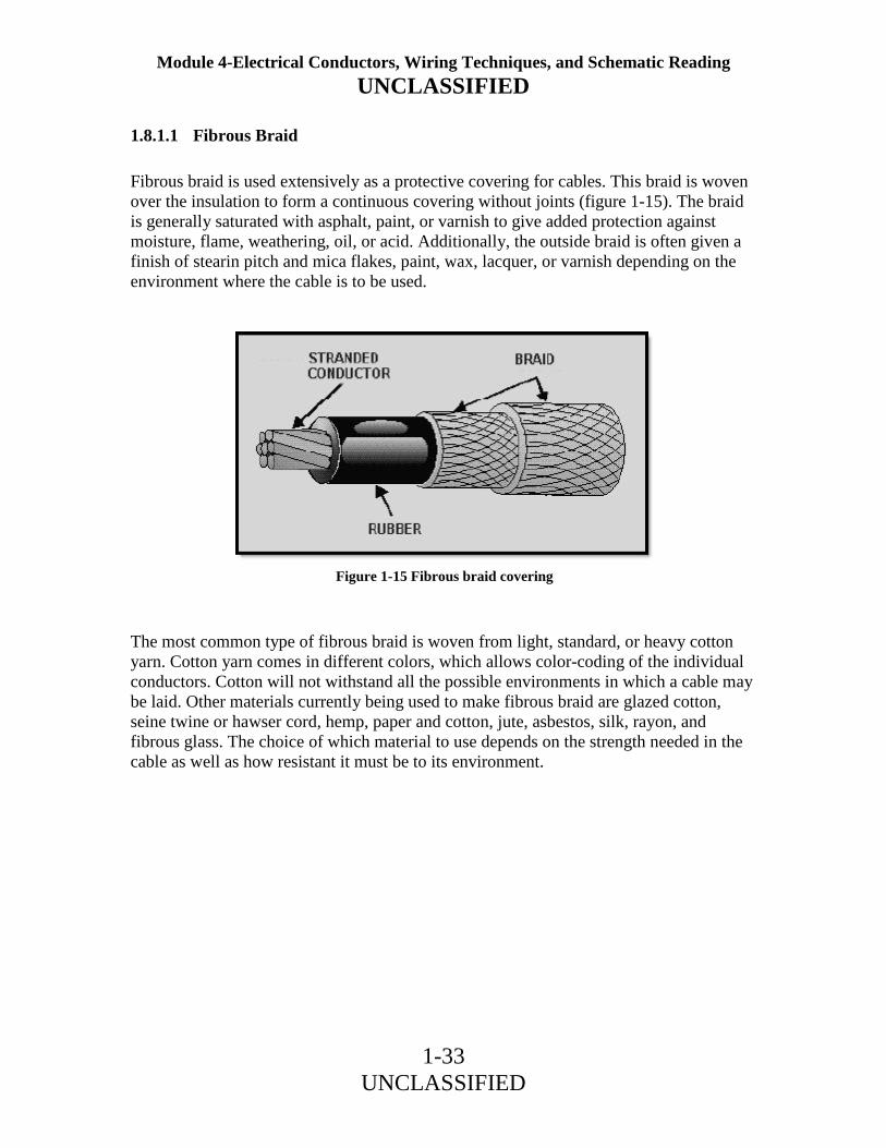
1.8.1.1 Fibrous Braid
Fibrous braid is used extensively as a protective covering for cables. This braid is woven over the insulation to form a continuous covering without joints (figure 1-15). The braid is generally saturated with asphalt, paint, or varnish to give added protection against moisture, flame, weathering, oil, or acid. Additionally, the outside braid is often given a finish of stearin pitch and mica flakes, paint, wax, lacquer, or varnish depending on the environment where the cable is to be used. The most common type of fibrous braid is woven from light, standard, or heavy cotton yarn. Cotton yarn comes in different colors, which allows color-coding of the individual conductors. Cotton will not withstand all the possible environments in which a cable may be laid. Other materials currently being used to make fibrous braid are glazed cotton, seine twine or hawser cord, hemp, paper and cotton, jute, asbestos, silk, rayon, and fibrous glass. The choice of which material to use depends on the strength needed in the cable as well as how resistant it must be to its environment.
Figure 1-15 Fibrous braid covering

Module 4-Electrical Conductors, Wiring Techniques, and Schematic Reading UNCLASSIFIED
1-34 UNCLASSIFIED
1.8.1.2 Fibrous Tape
Fibrous tape coverings are frequently used as a part of the protective covering of cables. The material of tape coverings is made into the tape before application to the cable. The material in yarns for braid covering is woven into fabric during the application to the cable. When tape covering is used, it is wrapped helically around the cable with each turn overlapping the previous turn. The most common types of fibrous tape are rubber-filled cloth tape and a combination of cotton cloth and rubber. Except for duct tape, tape covering is never used as the outer covering on a cable. Tape coverings are used directly over the insulation of individual conductors and for the inner covering over the assembled conductors of a multi-conductor cable. Frequently, tape coverings are used under the sheath of a lead-sheathed cable. Duct tape, which is made of heavy canvas webbing saturated with an asphalt compound, is often used over a lead-sheathed cable for protection against corrosion and mechanical injury. Q30. How many categories of nonmetallic protective coverings are there?
Q31. What is the most common type of nonmetallic material used to protect wires and cables?
Q32. What are the most common types of fibrous tape?
1.8.1.3 Woven Covers
Woven covers, commonly called loom, are used when exceptional abrasion-resistant qualities are required. These covers are composed of thick, heavy, long-fibered cotton yarns woven around the cable in a circular loom, much like that used on a fire hose. They are not braids, although braid covering are also woven; they are designated differently.

Module 4-Electrical Conductors, Wiring Techniques, and Schematic Reading UNCLASSIFIED
1-35 UNCLASSIFIED
1.8.1.4 Rubber and Synthetic Coverings
Rubber and synthetic coverings are not standardized. Different manufactures have their own special compounds designated by individual trade names. These compounds are different from the rubber compounds used to insulate cable. These compounds have been perfected not for insulation qualities but for resistance to abrasion, moisture, oil, gasoline, acids, earth solutions, and alkalies. None of these coverings will provide protection against all types of exposure. Each covering has its own particular limitations and qualifications. 1.8.1.5 Jute and Asphalt Coverings
Jute and asphalt coverings are commonly used as a cushion between cable insulation and metallic armor. Frequently, they are also used as a corrosive-resistant covering over a lead sheath or metallic armor. Jute and asphalt coverings consist of asphalt-impregnated jute yarn heli-wrapped around the cable or of alternate layers of asphalt-impregnated jute yarn. These coverings serve as a weatherproofing. 1.8.1.6 Unspun Felted Cotton
Unspun felted cotton is commonly used only in special classes of service. It is made as a solid felted covering for a cable. Q33. What materials are commonly used as cushions between cable insulation and metallic armor?

Module 4-Electrical Conductors, Wiring Techniques, and Schematic Reading UNCLASSIFIED
1-36 UNCLASSIFIED
1.8.2 Metallic Protection
Metallic protection is of two types: sheath or armor. As with all wires and cables, the type of protection needed will depend on the environment where the wire or cable will be used. 1.8.2.1 Metallic Sheath
Cables or wires that are continually subjected to water must be protected by a watertight cover. This watertight cover is either a continuous metal jacket or a rubber sheath molded around the cable. Figure 1-16 is an example of a lead-sheathed (jacketed) cable used in power work. This cable is a standard three-conductor type. Each conductor is insulated and then wrapped in a layer of rubberized tape. The conductors are twisted together, and rope or fillers are added to form a round core. Over this is wrapped a second layer of tape called a serving. Finally, a lead sheath is molded around the cable. Lead-sheathed cable is one of three types currently being used: alloy lead, pure lead, and reinforced lead. An alloy-lead sheath is much like a pure lead sheath but is manufactured with 2-percent tin. This alloy is more resistant to gouging and abrasion during and after installation. Reinforced lead sheath is used mainly for oil-filled cables where high internal pressures can be expected. Reinforced lead sheath consists of a double lead sheath. A thin tape of hard-drawn copper, bronze, or other elastic metal (preferably nonmagnetic) is wrapped around the inner sheath. This tape gives considerable additional strength and elasticity to the sheath, but must be protected from corrosion. For this reason, a second lead sheath is applied over the tape.
Figure 1-16 Lead-sheathed cable

Module 4-Electrical Conductors, Wiring Techniques, and Schematic Reading UNCLASSIFIED
1-37 UNCLASSIFIED
1.8.2.2 Metallic Armor
Metallic armor provides a tough protective covering for wires and cables. The type, thickness, and kind of metal used to make the armor depend on three factors: (1) the use of the conductors, (2) the environment where the conductors are to be used, and (3) the amount of rough treatment that is expected. Figure 1-17 shows three examples of metallic armor cable: wire braid, steel tape, and wire armor. WIRE-BRAID ARMOR - Wire-braid armor (view A of figure 1-17 ), also known as basket-weave armor, is used when light and flexible protection is needed. Wire braid is constructed much like fibrous braid. The metal is woven directly over the cable as the outer covering. The metal used in this braid is galvanized steel, bronze, copper, or aluminum. Wire-braid armor is mainly for shipboard use.
Figure 1-17 Metallic armor cable

Module 4-Electrical Conductors, Wiring Techniques, and Schematic Reading UNCLASSIFIED
1-38 UNCLASSIFIED
STEEL TAPE - A second type of metallic armor is steel tape. Steel tape covering (view B of figure 1-17) is wrapped around the cable and then covered with a serving of jute. There are two types of steel tape armor. The first is called interlocking armor. Interlocking armor is applied by wrapping the tape around the cable so that each turn is overlapped by the next and is locked in place. The second type is flat-band armor. Flat-band armor consists of two layers of steel tape. The first layer is wrapped around the cable but is not overlapped. The second layer is then wrapped around the cable covering the area that was not covered by the first layer. WIRE ARMOR - Wire armor is a layer of wound metal wire wrapped around the cable. Wire armor is usually made of galvanized steel and can be used over a lead sheath (see view C of figure 1-17). It can be used with the sheath as a buried cable where moisture is a concern, or without the sheath (view D of figure 1-17) when used in buildings. Q34. What are the two types of metallic protection?
Q35. What are the three types of lead-sheathed cables?
Q36. What are the three examples of metallic armor cable that were discussed?

Module 4-Electrical Conductors, Wiring Techniques, and Schematic Reading UNCLASSIFIED
1-39 UNCLASSIFIED
1.9 COAXIAL CABLE
Coaxial cable (figure 1-18) is defined as two concentric wires, cylindrical in shape, separated by a dielectric of some type. One wire is the center conductor and the other is the outer conductor. These conductors are covered by a protective jacket. The protective jacket is then covered by an outer protective armor. Coaxial cables are used as transmission lines and are constructed to provide protection against outside signal interference.
Figure 1-18 Coaxial cable

Module 4-Electrical Conductors, Wiring Techniques, and Schematic Reading UNCLASSIFIED
1-40 UNCLASSIFIED
1.10 SUMMARY
In this chapter you learned that conductors are the means for tying the various components of an electrical or electronic system together. Many factors determine the type of conductor to be used in a specific application. In order for you to compare the different types and sizes of conductors, we discussed the following factors: Unit Size - The unit size of a conductor is the mil-foot. A mil-foot is a circular conductor 1foot long with a diameter of 1 mil (0.001 inch, or one-thousandth of an inch). Conductor Sizes - The square mil and the circular mil are the units of measure used to determine the cross-sectional area of electrical conductors. The square mil, as it relates to a square conductor, is the cross-sectional area of a square conductor that has a side of 1 mil. The circular mil is the cross-sectional area of a circular conductor having a diameter of 1 mil. The circular mil area (CMA) of a conductor is computed by squaring the diameter of the circular conductor is mils. Thus, a wire having a diameter of 4 mils (0.004 inch) has a CMA of 42, or 16 circular mils. If the conductor is stranded, the CMA for a strand is computed, and the CMA for the conductor is computed by multiplying the CMA of the strand by the number of strands. The relationship of the square mil to the circular mil is determined by comparing the square mil area of a circular conductor having a diameter of 1 mil (A = πr2) to the circular mil area of the same conductor (D2). Therefore, there is 0.7854 square mil to 1 circular mil. There are more circular mils than square mils in a given area. Specific Resistance - The specific resistance of a substance is the resistance in ohms offered by a unit volume (the circular-mil-foot) to the flow of electric current. The three factors that are used to calculate the specific resistance of a particular conductor are (1) its length, (2) its cross-sectional area, and (3) the specific resistance of a unit volume of the substance from which the conductor is made. The specific resistance for various sizes and lengths of standard solid copper wire can be determined by the use of tables. Wire Gauge - A wire gauge is used to determine the American Standard Wire Gauge size of conductors. The measurement of a bare conductor is taken in the slot, not in the circular area at the bottom of the slot. Selection of Wire Size - Four factors must be considered in selecting the proper wire size for a particular electrical circuit. These factors are (1) conductor size, (2) the material it's made of, (3) the location of the wire in the circuit, and (4) the type of insulation used. Some of the types of insulation used in a high-temperature environment are FEP, extruded polytetrafluoroethylene, and silicone rubber. The ambient (surrounding) temperature of a conductor is an important part of total conductor heating.

Module 4-Electrical Conductors, Wiring Techniques, and Schematic Reading UNCLASSIFIED
1-41 UNCLASSIFIED
Copper-versus-Aluminum Conductors - The two most common metals used for electrical conductors are copper and aluminum. Some advantages of copper over aluminum as a conductor are that copper has higher conductivity, is more ductile, has a higher tensile strength, and can be easily soldered. Two advantages of aluminum wire for carrying electricity over long distances are its lightness and it reduces corona (the discharge of electricity from a wire at high potential). Temperature Coefficient of Resistance - The temperature coefficient of resistance is the amount of increase in the resistance of a 1-ohm sample of a conductor per degree of temperature rise above 0º C. The resistance of copper and other pure metals increases with an increase in temperature. Conductor Insulation - Insulators have a resistance that is so great that, for all practical purposes, they are nonconductors. Two fundamental properties of insulating materials are (1) insulation resistance and (2) the resistance to current leakage through the insulation. Dielectric strength is the ability of the insulation material to withstand potential difference. The dielectric strength of an insulator is determined by raising the voltage on a test sample until it breaks down. Insulating Materials - Some common insulating materials have properties and safety precautions that should be remembered. These are:
• The purpose of coating a copper conductor with tin when rubber insulation is used is to prevent the insulation from deteriorating due to chemical action.
• When extruded polytetrafluoroethylene insulation is heated, caution should be observed not to breathe the vapors.
• The most commonly used insulating materials for extremely high-voltage conductors are varnished cambric and oil-impregnated paper.
• Magnet wire is the common name for enamel-insulated wire used in meters, relays, small transformers, motor windings, and so forth.
• The Navy is getting away from using asbestos insulation because asbestos fibers can cause lung disease and/or cancer.
• Asbestos insulation becomes a conductor when it gets wet. Conductor Protection - There are several types of conductor protection in use. The type commonly used aboard Navy ships is wire-braid armor.

Module 4-Electrical Conductors, Wiring Techniques, and Schematic Reading UNCLASSIFIED
1-42 UNCLASSIFIED
ANSWERS TO QUESTIONS Q1. THROUGH Q36. A1. To allow comparisons between conductors of different sizes and resistance. A2. 375 mils (move the decimal three places to the right). A3. A circular conductor with a diameter of 1 mil and a length of 1 foot. A4. The cross-sectional area of a square conductor with a side of 1 mil. A5. The cross-sectional area of a circular conductor with a diameter of 1 mil. A6. Circular mil area (CMA) = D2 (in mils) × number of strands0.0004 inch = 4 mils (CMA) = 4 2 ×19 (strands)(CMA) = 16 × 19 = 304 mils. A7. The resistance of a unit volume of a substance. A8. Length, cross-sectional area, and specific resistance of a unit volume of the substance from which the conductor is made. A9. 1,000 ft = 10.4 ohms1,500 ft = 1.5 × 0.4 = 15.6 ohms A10. In the parallel walled slot not the circular area. A11. Conductor size, the material it is made of the location of the wire in a circuit, and the type of insulation used. A12. FEP, extruded polytetrafluoroethylene, and silicone rubber. A13. The heat surrounding the conductor is an important part of total conductor heating. A14. It is light and reduces corona. A15. It has higher conductivity, it is more ductile, it has relatively high tensile strength, and it can be easily soldered. A16. The amount of increase in the resistance of a 1-ohm sample of the conductor per degree of temperature rise above 0º C A17. It increases. A18. Conductors have a very low resistance and insulators have a resistance that is so great that, for all practical purposes, they are nonconductors.

Module 4-Electrical Conductors, Wiring Techniques, and Schematic Reading UNCLASSIFIED
1-43 UNCLASSIFIED
A19. Insulation resistance and dielectric strength. A20. The resistance to current leakage through the insulation. A21. The ability of the insulation material to withstand potential difference. A22. By raising the voltage on a test sample until it breaks down. A23. To prevent the rubber insulation from deteriorating due to chemical action. A24. Avoid breathing the vapors when the insulation is heated. A25. Breathing asbestos fibers can cause lung disease and/or cancer A26. It will become a conductor. A27. Varnished cambric and oil-impregnated paper. A28. Magnet wire. A29. Metallic coat. A30. Three. A31. Fibrous Braid. A32. Rubber-filled cloth tape and a combination of cotton cloth and rubber. A33. Jute and Asphalt coverings. A34. Sheath and armor A35. Alloy lead, pure lead, and reinforced lead. A36. Wire braid, steel tape, and wire armor

Module 4-Electrical Conductors, Wiring Techniques, and Schematic Reading UNCLASSIFIED
2-1 UNCLASSIFIED
2 WIRING TECHNIQUES
LEARNING OBJECTIVES Upon completing this chapter, you should be able to: 1. State the basic requirements for any splice and terminal connection, including the
preferred wire-stripping method. 2. State the reason the ends of the wire are clamped down after a Western Union splice
has been made. 3. Explain the major advantage of the crimped terminal over the soldered terminal. 4. Name the two types of insulation commonly used for noninsulated splices and
terminal lugs. 5. State an advantage of using preinsulated terminal lugs and the color code used for
each. 6. Explain the procedures for crimping terminal lugs with a hand crimp tool. 7. Recall the physical description and operating procedures for the HT-900B/920B
compressed air/nitrogen heating tool. 8. Recall the safety precautions for using the compressed air/nitrogen heating tool. 9. Recall the procedures, precautions, and tools associated with soldering. 10. Explain the procedures and precautions for tinning wire. 11. Recall the types of soldering irons and their uses. 12. State the purposes and required properties of flux. 13. State the purpose for lacing conductors. 14. Recall when double lacing of wire bundles is required. 15. Recall the requirements for using spot ties. 2.1 WIRING TECHNIQUES
This chapter will assist you in learning the basic skills of proper wiring techniques. It explains the different ways to terminate and splice electrical conductors. It also discusses various soldering techniques that will assist you in mastering the basic soldering skills. The chapter ends with a discussion of the procedure to be followed when you lace wire bundles within electrical and electronic equipment.
Module 4-Electrical Conductors, Wiring Techniques, and Schematic Reading UNCLASSIFIED
2-2 UNCLASSIFIED
2.2 CONDUCTOR SPLICES AND TERMINAL CONNECTIONS
Conductor splices and connections are an essential part of any electrical circuit. When conductors join each other or connect to a load, splices or terminals must be used. Therefore, it is important that they be properly made. Any electrical circuit is only as good as its weakest link. The basic requirement of any splice or connection is that it be both mechanically and electrically as sound as the conductor or device with which it is used. Quality workmanship and materials must be used to ensure lasting electrical contact, physical strength, and insulation. The most common methods of making splices and connections in electrical cables is explained in the discussion that follows. 2.2.1 Insulation Removal
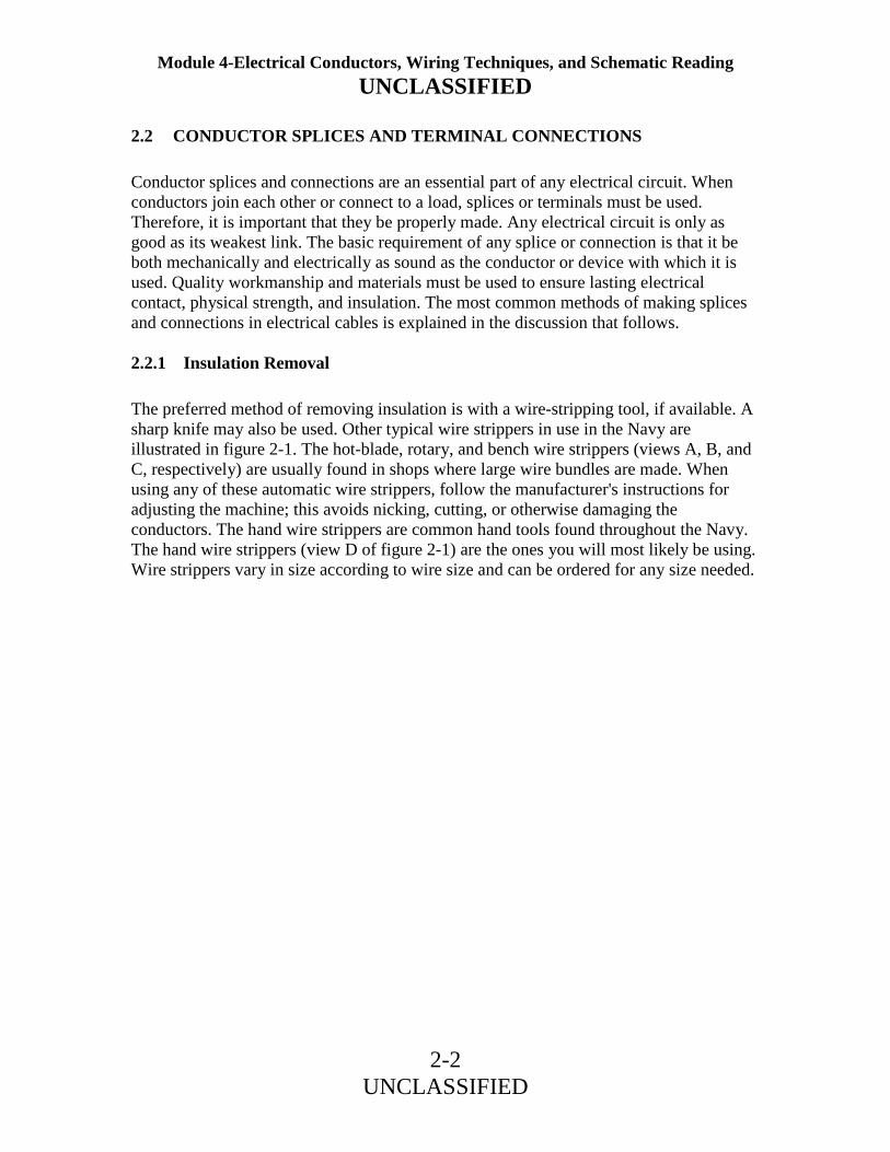
The preferred method of removing insulation is with a wire-stripping tool, if available. A sharp knife may also be used. Other typical wire strippers in use in the Navy are illustrated in figure 2-1. The hot-blade, rotary, and bench wire strippers (views A, B, and C, respectively) are usually found in shops where large wire bundles are made. When using any of these automatic wire strippers, follow the manufacturer's instructions for adjusting the machine; this avoids nicking, cutting, or otherwise damaging the conductors. The hand wire strippers are common hand tools found throughout the Navy. The hand wire strippers (view D of figure 2-1) are the ones you will most likely be using. Wire strippers vary in size according to wire size and can be ordered for any size needed.

Module 4-Electrical Conductors, Wiring Techniques, and Schematic Reading UNCLASSIFIED
2-3 UNCLASSIFIED
Figure 2-1 Typical wire-stripping tools

Module 4-Electrical Conductors, Wiring Techniques, and Schematic Reading UNCLASSIFIED
2-4 UNCLASSIFIED
2.2.1.1 Hand Wire Stripper
The procedure for stripping wire with the hand wire stripper is as follows (refer to figure 2-2): 1. Insert the wire into the center of the correct cutting slot for the wire size to be stripped. The wire sizes are listed on the cutting jaws of the hand wire strippers beneath each slot. 2. After inserting the wire into the proper slot, close the handles together as far as they will go. 3. Slowly release the pressure on the handles so as not to allow the cutting blades to make contact with the stripped conductor. On some of the newer style hand wire strippers, the cutting jaws have a safety lock that helps prevent this from happening. Continue to release pressure until the gripper jaws release the stripped wire, then remove.
Figure 2-2 Stripping wire with a hand stripper

Module 4-Electrical Conductors, Wiring Techniques, and Schematic Reading UNCLASSIFIED
2-5 UNCLASSIFIED
2.2.1.2 Knife Stripping
A sharp knife may be used to strip the insulation from a conductor. The procedure is much the same as for sharpening a pencil. The knife should be held at approximately a 60º angle to the conductor. Use extreme care when cutting through the insulation to avoid nicking or cutting the conductor. This procedure produces a taper on the cut insulation as shown in figure 2-3.
Figure 2-3 Knife stripping

Module 4-Electrical Conductors, Wiring Techniques, and Schematic Reading UNCLASSIFIED
2-6 UNCLASSIFIED
2.2.1.3 Locally Made Hot-Blade Wire Stripper
If you are required to strip a large number of wires, you can use a locally made hot-blade stripper (figure 2-4) as follows: 1. In the end of a piece of copper strip, cut a sharp-edged "V." At the bottom of the "V," make a wire slot of suitable diameter for the size wire to be stripped. 2. Fasten the copper strip around the heating element of an electric soldering iron as shown in figure 2-4. The iron must be rated at 100 watts or greater in order to transfer enough heat to the copper strip to melt the wire insulation. 3. Lay the wire or cable to be stripped in the "V"; a clean channel will be melted in the insulation. 4. Remove the insulation with a slight pull.
Figure 2-4 Locally made hot-blade stripper

Module 4-Electrical Conductors, Wiring Techniques, and Schematic Reading UNCLASSIFIED
2-7 UNCLASSIFIED
2.2.1.4 General Wire-Stripping Instructions
When stripping wire with any of the tools mentioned, observe the following precautions: 1. Do not attempt to use a hot-blade stripper on wiring with glass braid or asbestos insulation. These insulators are highly heat resistant. 2. When using the hot-blade stripper, make sure the blades are clean. Clean the blades with a brass wire brush as necessary. 3. Make sure all stripping blades are sharp and free from nicks, dents, and so forth. 4. When using any type of wire stripper, hold the wire perpendicular to the cutting blades. 5. Make sure the insulation is clean-cut with no frayed or ragged edges; trim if necessary. 6. Make sure all insulation is removed from the stripped area. Some types of wire are supplied with a transparent layer between the conductor and the primary insulation. If this is present, remove it. 7. When the hand strippers are used to remove lengths of insulation longer than 3/4 inch, the stripping procedure must be done in two or more operations. The strippers will only strip about 3/4 inch at one time. 8. Retwist strands by hand, if necessary, to restore the natural lay and tightness of the strands. 9. Strip aluminum wires with a knife as described earlier. Aluminum wire should be stripped very carefully. Care should be taken not to nick the aluminum wire as the strands break very easily when nicked. Q1. What are the basic requirements for any splice or terminal connection?
Q2. What is the preferred method for stripping wire?

Module 4-Electrical Conductors, Wiring Techniques, and Schematic Reading UNCLASSIFIED
2-8 UNCLASSIFIED
Q3. What stripping tool would NOT be used to strip glass braid insulation?
Q4. What tool should be used to strip aluminum wire?
2.2.2 TYPES OF SPLICES
There are six commonly used types of splices. Each has advantages and disadvantages for use. Each splice will be discussed in the following section. 2.2.2.1 Western Union Splice
The Western Union splice joins small, solid conductors. Figure 2-5 shows the steps in making a Western Union splice.
Figure 2-5 Western Union splice

Module 4-Electrical Conductors, Wiring Techniques, and Schematic Reading UNCLASSIFIED
2-9 UNCLASSIFIED
1. Prepare the wires for splicing. Enough insulation is removed to make the splice. The conductor is cleaned. 2. Bring the wires to a crossed position and make a long twist or bend in each wire. 3. Wrap one end of the wire and then the other end four or five times around the straight portion of each wire. 4. Press the ends of the wires down as close as possible to the straight portion of the wire. This prevents the sharp ends from puncturing the tape covering that is wrapped over the splice. The various types of tape and their uses are discussed later in this chapter. 2.2.2.2 Staggering Splices
Joining small multiconductor cables often presents a problem. Each conductor must be spliced and taped. If the splices are directly opposite each other, the overall size of the joint becomes large and bulky. A smoother and less bulky joint can be made by staggering the splices. Figure 2-6 shows how a two-conductor cable is joined to a similar size cable by using a Western Union splice and by staggering the splices. Care should be taken to ensure that a short wire from one side of the cable is spliced to a long wire, from the other side of the cable. The sharp ends are then clamped firmly down on the conductor. The figure shows a Western Union splice, but other types of splices work just as well.
Figure 2-6 Staggering splices

Module 4-Electrical Conductors, Wiring Techniques, and Schematic Reading UNCLASSIFIED
2-10 UNCLASSIFIED
2.2.2.3 Rattail Joint
A splice that is used in a junction box and for connecting branch circuits is the rattail joint (figure 2-7). Wiring that is installed in buildings is usually placed inside long lengths of steel or aluminum pipe called a conduit. Whenever branch or multiple circuits are needed, junction boxes are used to join the conduit. To create a rattail joint, first strip the insulation off the ends of the conductors to be joined. You then twist the wires to form the rattail effect. This type of splice will not stand much stress.
Figure 2-7 Rattail joint

Module 4-Electrical Conductors, Wiring Techniques, and Schematic Reading UNCLASSIFIED
2-11 UNCLASSIFIED
2.2.2.4 Fixture Joint
The fixture joint is used to connect a small-diameter wire, such as in a lighting fixture, to a larger diameter wire used in a branch circuit. Like the rattail joint, the fixture joint will not stand much strain. Figure 2-8 shows the steps in making a fixture joint. The first step is to remove the insulation and clean the wires to be joined. After the wires are prepared, the fixture wire is wrapped a few times around the branch wire. The end of the branch wire is then bent over the completed turns. The remainder of the bare fixture wire is then wrapped over the bent branch wire. Soldering and taping completes the job.
Figure 2-8 Fixture joint

Module 4-Electrical Conductors, Wiring Techniques, and Schematic Reading UNCLASSIFIED
2-12 UNCLASSIFIED
2.2.2.5 Knotted Tap Joint
All the splices discussed up to this point are known as butted splices. Each was made by joining the free ends of the conductors together. Sometimes, however, it is necessary to join a branch conductor to a continuous wire called the main wire. Such a junction is called a tap joint. The main wire, to which the branch wire is to be tapped, has about 1 inch of insulation removed. The branch wire is stripped of about 3 inches of insulation. The knotted tap is shown in figure 2-9. The branch wire is laid behind the main wire. About three-fourths of the bare portion of the branch wire extends above the main wire. The branch wire is brought under the main wire, around itself, and then over the main wire to form a knot. The branch wire is then wrapped around the main conductor in short, tight turns; and the end is trimmed off. The knotted tap is used where the splice is subject to strain or slippage. When there is no strain, the knot may be eliminated.
Figure 2-9 Knotted tap joint

Module 4-Electrical Conductors, Wiring Techniques, and Schematic Reading UNCLASSIFIED
2-13 UNCLASSIFIED
2.2.2.6 Wire Nut and Split Bolt Splices
The wire nut (view A of figure 2-10) is a device commonly used to replace the rattail joint splice. The wire nut is housed in plastic insulating material. To use the wire nut, place the two stripped conductors into the wire nut and twist the nut. In so doing, this will form a splice like the rattail joint and insulate itself by drawing the wire insulation into the wire nut insulation. The split bolt splice (view B of figure 2-10) is used extensively to join large conductors. In the illustration, it is shown replacing the knotted tap joint. The split bolt splice can also be used to replace the "butted" splices mentioned previously when using large conductors. Q5. Why are the ends of the wire clamped down after a Western Union splice is made?
Q6. Why are splices staggered on multiconductor cables?
Figure 2-10 Wire nut and split bolt splices

Module 4-Electrical Conductors, Wiring Techniques, and Schematic Reading UNCLASSIFIED
2-14 UNCLASSIFIED
Q7. Where is the rattail joint normally used?
Q8. Which type of splice is used to splice a lighting fixture to a branch circuit?
2.2.3 Splice Insulation
The splices we have discussed so far are usually insulated with tape. The following discussion will cover some characteristics of rubber, friction, and plastic insulation tapes. 2.2.3.1 Rubber Tape
Latex (rubber) tape is a splicing compound. It is used where the original insulation was rubber. The tape is applied to the splice with a light tension so that each layer presses tightly against the one beneath it. This pressure causes the rubber tape to blend into a solid mass. Upon completion, insulation similar to the original is restored. In roll form, there is a layer of paper or treated cloth between each layer of rubber tape. This layer prevents the latex from fusing while still on the roll. The paper or cloth is peeled off and discarded before the tape is applied to the splice. The rubber splicing tape should be applied smoothly and under tension so no air space exists between the layers. Start the first layer near the middle of the joint instead of the end. The diameter of the completed insulated joint should be somewhat greater than the overall diameter of the original wire, including the insulation.
WARNING
Some rubber tapes are made for special applications. These types are semiconducting and will pass electrical current, which presents a shock hazard. These types of tape are packaged similar to the latex rubber tape. Care should be taken to insulate splices only with latex rubber insulating tape.

Module 4-Electrical Conductors, Wiring Techniques, and Schematic Reading UNCLASSIFIED
2-15 UNCLASSIFIED
2.2.3.2 Friction Tape
Putting rubber tape over the splice means that the insulation has been restored to a great degree. It is also necessary to restore the protective covering. Friction tape is used for this purpose. It also provides a minor degree of electrical insulation. Friction tape is a cotton cloth that has been treated with a sticky rubber compound. It comes in rolls similar to rubber tape except that no paper or cloth separator is used. Friction tape is applied like rubber tape; however, it does not stretch. The friction tape should be started slightly back on the original insulation. Wind the tape so that each turn overlaps the one before it. Extend the tape over onto the insulation at the other end of the splice. From this point, a second layer is wound back along the splice until the original starting point is reached. Cutting the tape and firmly pressing down the ends completes the job. When proper care is taken, the splice and insulation can take as much abuse as the rest of the original wire. 2.2.3.3 Plastic Electrical Tape
Plastic electrical tape has come into wide use in recent years. It has certain advantages over rubber and friction tape. For example, it can withstand higher voltages for a given thickness. Single thin layers of certain plastic tape will withstand several thousand volts without breaking down. However, to provide an extra margin of safety, several layers are usually wound over the splice. The extra layers of thin tape add very little bulk. The additional layers of plastic tape provide the added protection normally furnished by friction tape. Plastic electrical tape usually has a certain amount of stretch so that it easily conforms to the contour of the splice. Q9. Which of the splices discussed is NOT a butted splice?
Q10. Why is friction tape used in splicing?

Module 4-Electrical Conductors, Wiring Techniques, and Schematic Reading UNCLASSIFIED
2-16 UNCLASSIFIED
2.2.4 Terminal Lugs
Since most cable wires are stranded, it is necessary to use terminal lugs to hold the strands together to aid in fastening the wires to terminal studs (see figure 2-11). The terminals used in electrical wiring are either of the soldered or crimped type. Terminals used in repair work must be of the size and type specified on the electrical wiring diagram for the particular equipment. The increased use of crimp-on terminals is due to the limitations of soldered terminals. The quality of soldered connections depends mostly upon the operator's skill. Other factors, such as temperature, flux, cleanliness, oxides, and insulation damage due to heat, also add to defective connections. Solder-type connections are covered later in this chapter.
Figure 2-11 Noninsulated terminal lugs and splices

Module 4-Electrical Conductors, Wiring Techniques, and Schematic Reading UNCLASSIFIED
2-17 UNCLASSIFIED
An advantage of the crimp-on solderless terminal lugs is that they require relatively little operator skill to use. Another advantage is that the only tool needed is the crimping tool. This allows terminal lugs to be applied with a minimum of time and effort. The connections are made rapidly, are clean, and uniform in construction. Because of the pressures exerted and the material used, the crimped connection or splice, properly made, is both mechanically and electrically sound. Some of the basic types of terminals are shown in figure 2-11. There are several variations of these basic types, such as the use of a slot instead of a terminal hole, three- and four-way splice-type connectors, and others. Since the Navy uses both copper and aluminum wiring, both copper and aluminum terminals are necessary. Various size terminal or stud holes may be found for each of the different wire sizes. A further refinement of the solderless terminals and splices is the insulated type. The barrel of the terminal or splice is enclosed in an insulated material. The insulation is compressed along with the terminal barrel when it is crimped, but is not damaged in the process. This rids you of the need for taping or tying an insulating sleeve over the joint. There are several different types of crimping tools used with copper terminals. However, you will normally be concerned only with wire sizes AWG (American Wire Gauge) 10 or smaller. For wire of these sizes, a small plier-type crimper is used to crimp on uninsulated terminals, as shown in figure 2-12. The small plier-type crimper has several sizes of notches for the different size terminals. Care should be used to select the correct size crimping tool for the particular terminal.
Figure 2-12 Crimping small copper uninsulated terminals

Module 4-Electrical Conductors, Wiring Techniques, and Schematic Reading UNCLASSIFIED
2-18 UNCLASSIFIED
2.2.5 Noninsulated Terminal and Splice Insulation
When noninsulated terminals and splices are used, some form of insulation must be used to cover the bare conductor. The two most common forms of insulator used for terminals and splices are transparent tubing (commonly called spaghetti) and heat-shrinkable tubing. If spaghetti is used, it must be tied with lacing twine, as illustrated in figure 2-13. Heat-shrinkable tubing is shrunk to the desirable size by applying dry heat. It is also a good way to insulate terminals and splices, as illustrated in figure 2-14. This tubing shrinks to approximately one-half its original diameter when heated with an electrical hot-air gun (figure 2-15). Here are the steps for using the hot-air gun:
Figure 2-13 Spaghetti tied with lacing twine
Figure 2-14 Shrunken sleeve

Module 4-Electrical Conductors, Wiring Techniques, and Schematic Reading UNCLASSIFIED
2-19 UNCLASSIFIED
1. Hold the heat source 4 to 5 inches away from the wire. Apply a heat of 275º F to 300º F for about 30 seconds. Rotate the wire while applying the heat so that the heat is evenly distributed. 2. Remove the heat as soon as the tubing conforms to the shape of the wire. Allow the tubing to cool for at least 30 seconds before handling.
CAUTION
Do not apply heat higher than 300º F as this may damage the wire. Do not continue to apply heat after the tubing has shrunk onto the wire. Further application of heat will not cause additional shrinkage of the tubing.
Figure 2-15 Typical hot-air gun

Module 4-Electrical Conductors, Wiring Techniques, and Schematic Reading UNCLASSIFIED
2-20 UNCLASSIFIED
2.2.6 Compressed Air/Nitrogen Heating Tool
The compressed air/nitrogen heating tool (figure 2-16) is a new tool in the fleet and was designed as a portable source of heat. This tool is safe for use around fueled aircraft because an open heating element is not required. The compressed air/nitrogen heating tool can be used on heat-shrinkable tubing. The compressed air/nitrogen heating tool comes in two styles: ac or dc electrical power supplies. The power requirements are listed in table 2-1 for both styles.
Table 2-1 Compressed Air/Nitrogen Heating Tool Power Requirements
Electrical Power, HT-900B 115 VAC, 50-400 Hz, single-phase, 7 Amps Electrical Power, HT-920B 220 VAC, 50-400 Hz, single-phase, 3.5 Amps Heat gun output temperature 550-920°F (290-495°C) Compressed air/nitrogen 80-200 psig, 4 SCFM (Dry and oil-free)
Figure 2-16 Compressed air/nitrogen heating tool

Module 4-Electrical Conductors, Wiring Techniques, and Schematic Reading UNCLASSIFIED
2-21 UNCLASSIFIED
Refer to the operator's manual for safe operating procedures for the compressed air/nitrogen heating tool. A brief summary of these procedures follows: 1. Push down and fully turn the air regulator knob counterclockwise. This is to ensure that the air regulator is off. 2. Remove the dust cap from the air inlet nipple. The inlet nipple is what we connect the air or nitrogen source line to.
WARNING
If nitrogen is used, make sure that you are in a well-ventilated area. Using nitrogen is a poorly ventilated area. Using nitrogen is a poorly ventilated area can result in suffocation.
CAUTION
As noted in table 2-1, the compressed air/nitrogen source CANNOT be greater than 200 psig. 3. Attach the air/nitrogen hose to the inlet nipple, making sure there is a firm connection. 4. Once the air/nitrogen source is properly attached, push down and turn the air regulator knob clockwise until the pressure on the air pressure gauge indicates between 5 to 7 psig. 5. Plug in the power cord to an appropriate grounded power supply. 6. Set the power switch to the ON position. The power lamp and heated-air-on lamp will both illuminate. (If the lights do not come on, check the switch on the gun handle. The switch must be positioned toward the front of the handle.) 7. There is a 1-minute warm-up time. During this warm-up period, ensure that the indicated air pressure increases to 10 to 15 psig on the air-pressure gauge. 8. You can now adjust the temperature control knob to the desired temperature setting. 9. You can turn the air/nitrogen pressure off and on to the gun without powering down the module by using the switch mounted on the gun handle.

Module 4-Electrical Conductors, Wiring Techniques, and Schematic Reading UNCLASSIFIED
2-22 UNCLASSIFIED
After you complete your task with the compressed air/nitrogen heating tool, use the following shutdown procedures: 1. Push down and fully turn the air regulator knob counterclockwise. Observe that the air pressure gauge indication drops to 0 psig and the heated air lamp goes out. 2. Position the switch on the heating gun toward the rear of the handle. 3. Place the power switch to the OFF position and observe that the power lamp goes out. 4. Allow the air/nitrogen to flow for a minimum of 1 minute to cool the heating gun. (This procedure is done to extend the life of the heating element.) 5. Disconnect the power connecter from the power source. 6. Turn off air/nitrogen source at place of origin and disconnect. 7. Disconnect the compressed air/nitrogen hose from the air inlet nipple and install the dust cap on the air inlet nipple. 2.2.6.1 Noninsulated Copper Terminals
The procedure for crimping a copper terminal (noninsulated) to a copper wire is as follows: 1. With a wire stripper, trim the insulation from the wire about one thirty-second of an inch longer than the length of the terminal barrel. When using a wire stripper, be sure to use the correct size stripping slot for the wire size used. Otherwise, all the insulation will not be removed or, if the slot is too small, the outside strands of the conductor will be nicked and consequently weakened. When a knife is used for stripping wire, care should be used to prevent nicking the strands. Slip the spaghetti or heat-shrinkable tubing over the wire and back far enough to be out of the way of the crimping operation. 2. Slip the terminal barrel over the bared wire end and up against the insulation. Make certain that all wire strands are inside the tubular barrel of the terminal. 3. Center the terminal barrel in the female nest of the plier jaws as shown in figure 2-12 so that the indentation formed by the staking die will be in the center of the barrel. Crimp until the pliers reach their stop or limit. This is necessary for a good mechanical and electrical connection.

Module 4-Electrical Conductors, Wiring Techniques, and Schematic Reading UNCLASSIFIED
2-23 UNCLASSIFIED
4. Slip the tubular insulation down over the terminal barrel so that it extends a little beyond the barrel. Tie it in place if spaghetti is used. If heat-shrinkable tubing is used, shrink with a heat gun. Q11. What is a major advantage of the crimped terminal over the soldered terminal?
Q12. What are the two types of insulation most commonly used for noninsulated splices and terminal lugs?
Q13. What is the maximum allowable temperature that should be used on heat-shrinkable tubing?
Q14. What is the maximum allowable source pressure that can be used with the compressor air/nitrogen heating tool?
2.2.7 Aluminum Terminals and Splices
Terminals that are used with aluminum wire are made of aluminum. Proper crimping is more difficult with these terminals because of such factors as aluminum creep and softness. Aluminum wire has an undesirable characteristic called aluminum creep. Aluminum has the tendency to actually move away from the point where pressure is applied. This is not only true during the crimping operation but also takes place during temperature changes. The aluminum wire is softer than the terminal lugs and splice connectors and contracts faster than the connector when the temperature drops. This causes the wires to creep away from the crimped connections, which, in turn, causes loose connections. The softness of aluminum wire also makes it subject to being cut or nicked during stripping. You should be careful never to use an aluminum terminal with copper wire or a copper terminal with aluminum wire because of electrolysis. Electrolysis is the chemical action that takes place when an electric current passes through two dissimilar metals. This chemical action corrodes (eats away) the metal. Also, never use the aluminum crimping tool for crimping other than the aluminum terminals. Aluminum terminal lugs and splices are not insulated, so you must use spaghetti or heat-shrinkable tubing for insulation as discussed earlier.

Module 4-Electrical Conductors, Wiring Techniques, and Schematic Reading UNCLASSIFIED
2-24 UNCLASSIFIED
The barrels of several styles of larger size aluminum terminal lugs are filled with a petroleum abrasive compound. This compound causes a grinding action during the crimping operation. This removes the oxide film from the aluminum. It also prevents the oxide film from reforming in the connection. All aluminum terminals and splices have an inspection hole to allow checking the depth of wire insertion. This hole is sealed with a removable plug, which also serves to hold in the oxide-inhibiting compound (figure 2-17).
Figure 2-17 Aluminum terminal lug and splice

Module 4-Electrical Conductors, Wiring Techniques, and Schematic Reading UNCLASSIFIED
2-25 UNCLASSIFIED
It is recommended that only power-operated crimping tools be used to install large aluminum terminal lugs and splices. (See view A of figure 2-18.) The steps used for crimping an aluminum terminal or splice to an aluminum wire (view B of figure 2-18) is as follows: 1. Carefully remove the conductor insulation. Do not cut or nick the aluminum conductors. Do not wire-brush or scrape the aluminum conductor (the compound in the terminal or splice barrel will clean it satisfactorily). 2. Remove the protective foil wrapping from the terminal or splice and check the amount of compound in the terminal barrel. It should be one-fourth to one-half full.
Figure 2-18 Power crimping tools

Module 4-Electrical Conductors, Wiring Techniques, and Schematic Reading UNCLASSIFIED
2-26 UNCLASSIFIED
3. Slip the spaghetti or heat-shrinkable tubing over the wire and back far enough to be out of the way of the crimping operation. Insert the stripped conductor the full length of the terminal or splice barrel. While doing this, leave the plug over the inspection hole. This allows the compound to be forced in and around the strands. 4. Center the terminal lug or splice in the crimping tool. 5. Actuate the power crimping tool. 6. Wipe off the excess compound. Inspect the joint with a probe through the inspection hole. The end of the conductor should come to the edge of the inspection hole. 7. Slip the tubular insulation down over the terminal or splice barrel. Tie it in place if spaghetti is used. If using heat-shrinkable tubing, shrink with a heat gun. Q15. Should aluminum wire be cleaned prior to installing an aluminum terminal lug or splice?
Q16. What tools should be used to install large aluminum terminal lugs and splices?
Q17. Why should a lockwasher never be used with an aluminum terminal?
Improper crimping procedures eventually cause terminal failure. Be especially careful of under crimping, over crimping, using wrong crimping tools, improper cleaning methods, and cutting or nicking the conductors. A loose contact allows an oxide film to form between the wire and the terminal. This results in increased resistance, and the resistance causes heat. The heat accelerates deterioration, and eventually a failure results.

Module 4-Electrical Conductors, Wiring Techniques, and Schematic Reading UNCLASSIFIED
2-27 UNCLASSIFIED
2.2.8 Preinsulated Copper Terminal Lugs and Splices
The use of preinsulated terminal lugs and splices has become the most common method for copper wire termination and splicing in recent years. It is by far the best and easiest method. There are many tools used for crimping terminal lugs and splices. Hand, portable power, and stationary power tools are available for crimping terminal lugs. These tools crimp the barrel to the conductor and, at the same time, form the insulation support to the wire insulation. The power tools, both stationary and portable, are usually found in large shops where wire bundles are made up. In the next paragraphs, we will discuss the more common hand-crimping tools you will most likely be using in your day-to-day work. 2.2.9 Terminating Copper Wire with Preinsulated Terminal Lugs
Small-diameter copper wires are terminated with solderless, preinsulated copper terminal lugs. As shown in figure 2-19, the insulation is part of the terminal lug. It extends beyond the barrel so that it covers a portion of the wire insulation. This makes the use of spaghetti or heat-shrinkable tubing unnecessary. Preinsulated terminal lugs also have an insulation support (a metal reinforcing sleeve) beneath the insulation for extra supporting strength of the wire insulation. Some preinsulated terminals fit more than one size of wire. The insulation is color coded, and the range of wire sizes is marked on the tongue. This identifies the wire sizes that can be terminated with each of the terminal lug sizes. (See table 2-2.)
Figure 2-19 Preinsulated straight copper terminal lug

Module 4-Electrical Conductors, Wiring Techniques, and Schematic Reading UNCLASSIFIED
2-28 UNCLASSIFIED
Table 2-2 Color Coding of Copper Terminal Lug or Splice Insulation
Color of Terminal Lug or Splice Insulation To Be Used on Wire Sizes Yellow (Bright) #26 - #24 Red #22 - #20, #18 Blue #16 - #14 Yellow (Dull) #12 - #10
For crimping small copper terminal lugs, several hand-crimping tools can be used for wire sizes AWG 26 through 10 (figure 2-20). These hand-crimping tools have a self-locking ratchet, which prevents the tool from opening until the crimp is completed. Some of these tools have a color-coded selector knob to match the color-coded terminal lug or splice being used. Other tools have a replaceable set of dies for several wire sizes. The hand-crimping procedure for preinsulated copper terminal lugs in wire sizes No. 26 through No. 10 with the standard hand-crimp tool is as follows:
Figure 2-20 Hand-crimping tools

Module 4-Electrical Conductors, Wiring Techniques, and Schematic Reading UNCLASSIFIED
2-29 UNCLASSIFIED
1. Strip the wire insulation using the recommended stripping procedures already discussed. 2. Ensure that the tool handles are fully open and the proper die set has been installed correctly. 3. Insert the terminal lug, tongue first, into the wire side of the hand tool barrel crimping jaws. Be certain the terminal lug barrel butts flush against the tool stop on the locator. See figure 2-21 for the correct insertion method. 4. Squeeze the tool handles slowly until the tool jaws hold the terminal lug barrel firmly in place, but without denting it. 5. Insert the stripped wire into the terminal lug barrel until the wire insulation butts flush against the near end of the wire barrel. (See figure 2-22.)
Figure 2-21 Crimping tool with terminal lug inserted

Module 4-Electrical Conductors, Wiring Techniques, and Schematic Reading UNCLASSIFIED
2-30 UNCLASSIFIED
6. Squeeze the tool handles until the ratchet releases. 7. Remove the completed assembly and examine it for the proper crimp in accordance with the following:
a. Indent centered on the terminal lug barrel. b. Indent in line with the barrel. c. Terminal lug not cracked. d. Terminal lug insulation not cracked. e. Insulation grip crimped.
CAUTION
If not properly stripped, some of the smaller gauge, thin-wall wire insulation can be inadvertently inserted and crimped in the terminal wire barrels. This will cause a bad electrical connection. Do not use any connection that is found defective as a result of a visual inspection. Cut off the defective connection and remake using a new terminal lug.
Figure 2-22 Proper insertion of stripped wire in insulation terminal lug for crimping

Module 4-Electrical Conductors, Wiring Techniques, and Schematic Reading UNCLASSIFIED
2-31 UNCLASSIFIED
2.2.10 Preinsulated Splices
Preinsulated permanent copper splices are used to join small copper wire AWG sizes No. 26 through No. 10. A typical splice is shown in figure 2-23. Note that the splice preinsulation extends over the wire insulation. Each splice size can be used for more than one wire size. Splices are color coded in the same manner as preinsulated small copper terminal lugs (see table 2-2). 2.2.10.1 Crimping Procedure for Splices
Crimping small preinsulated copper splices in the No. 26 to No. 14 wire-size range can be accomplished with several recommended tools. In this section, we will discuss the basic crimping procedures. 1. Strip wire to length following one of the procedures already discussed. 2. With the tool handles fully open, set the wire size selector knob to the proper position for the wire size being crimped. Slide the terminal lug locator down below the die surface into the fully retracted position. (See figure 2-24.) Slide the splice locator back into the retracted position. Insert the splice into the tool so that the "locating shoulder" on the side of the splice to be crimped is in the space between the two crimping dies. The insulation barrel on this side of the splice should protrude from the "wire side" of the tool. (See figure 2-24.) Slide the splice locator into the fully extended position. Insert the splice into the stationary die so that the locator "finger" fits into the locator groove in the splice.
Figure 2-23 Preinsulated copper splice

Module 4-Electrical Conductors, Wiring Techniques, and Schematic Reading UNCLASSIFIED
2-32 UNCLASSIFIED
3. Squeeze the tool handles slowly until the tool jaws hold the spice barrel firmly in place, but without denting he barrel. 4. Insert the stripped wire into the splice barrel, which protrudes from the "wire side" of the splice, until the stripped end of wire butts against the stop in the center of the splice. This can be seen through the splice inspection window. 5. Crimp by closing the tool handles. The tool will not open until the full crimping cycle has been completed. 6. After crimping, check that the wire end is still visible through the splice inspection window. 7. Reverse the position of the splice in the crimping tool (or location of the crimping tool on the splice) and repeat steps 1 through 6 to crimp the wire into the other side of the splice.
Figure 2-24 Locating splice in crimping tool

Module 4-Electrical Conductors, Wiring Techniques, and Schematic Reading UNCLASSIFIED
2-33 UNCLASSIFIED
If the correct tools are used and the proper procedures followed, crimp-on connections are more effective electrically, as well as mechanically, than soldered connections. A visual inspection is very important. It reveals oxidation, deterioration, overheating, and broken conductors. In some cases it may be necessary to check these connections with an ohmmeter. The proper resistance, for all practical purposes, should be zero. Any defective terminal should be removed and a new terminal crimped on. Q18. What is the most common method of terminating and splicing wires?
Q19. Besides not having to insulate a noninsulated terminal, what other advantage is gained by using a preinsulated terminal lug?
Q20. Why are preinsulated terminal lugs and splices color coded?

Module 4-Electrical Conductors, Wiring Techniques, and Schematic Reading UNCLASSIFIED
2-34 UNCLASSIFIED
2.3 SOLDERING
The following information will aid you in learning basic soldering skills. It should enable you to solder wires to electrical connectors, splices, and terminal lugs that we have discussed earlier in the chapter. Special skills and schooling are required for the soldering techniques used in printed circuit boards and microminiature component repair. 2.3.1 Soldering Process
Cleanliness is essential for efficient, effective soldering. Solder will not adhere to dirty, greasy, or oxidized surfaces. Heated metals tend to oxidize rapidly. This is the reason the oxides, scale, and dirt must be removed by chemical or mechanical means. Grease or oil films can be removed with a suitable solvent. Connections to be soldered should be cleaned just prior to the actual soldering operation. Items to be soldered should normally be "tinned" before making a mechanical connection. Tinning is the coating of the material to be soldered with a light coat of solder. When the surface has been properly cleaned, a thin, even coating of flux should be placed over the surface to be tinned. This will prevent oxidation while the part is being heated to soldering temperature. Rosin-core solder is usually preferred in electrical work. However, a separate rosin flux may be used instead. Separate rosin flux is frequently used when wires in cable fabrication are tinned. Q21. Why must items to be soldered be cleaned just prior to the soldering process?
2.3.2 Tinning Copper Wire and Cable
Wires to be soldered to connectors should be stripped so that when the wire is placed in the barrel; there will be a gap of approximately 1/32 inch between the end of the barrel and the end of the insulation. This is done to prevent burning the insulation during the soldering process and to allow the wire to flex easier at a stress point. Before copper wires are soldered to connectors, the ends exposed by stripping are tinned to hold the strands solidly together. The tinning operation is satisfactory when the ends and sides of the wire strands are fused together with a coat of solder. Do not tin wires that are to be crimped to solderless terminals or splices.

Module 4-Electrical Conductors, Wiring Techniques, and Schematic Reading UNCLASSIFIED
2-35 UNCLASSIFIED
Copper wires are usually tinned by dipping them into flux (view A of figure 2-25) and then into a solder bath (pot) (view B of the figure). In the field, copper wires can be tinned with a soldering iron and rosin-core solder. Tin the conductor for about half its exposed length. Tinning or solder on the wire above the barrel causes the wire to be stiff at the point where flexing takes place. This will result in the wire breaking. The flux used in tinning copper wire is a mixture of denatured alcohol and freshly ground rosin. This type of flux may be mixed just prior to use. A premixed paste flux may also be used. The solder used for terminal lugs, splices, and connectors is a mixture of 60-percent tin and 40-percent lead. Maintain the temperature of the solder bath (pot) between 450 and 500º F. This keeps the solder in a liquid state. Skim the surface of the solder pot, as necessary, with a metal spoon or blade. This keeps the solder clean and free from oxides, dirt, and so forth.
Figure 2-25 Dip-tinning In a solder pot

Module 4-Electrical Conductors, Wiring Techniques, and Schematic Reading UNCLASSIFIED
2-36 UNCLASSIFIED
Dip-tin wires smaller than No. 8 in groups of 8 or 10. Dip-tin wires size No. 8 and larger individually. The procedure for dip-tinning is as follows: 1. Prepare the flux and solder as previously described. 2. Make sure the exposed end of the wire is clean and free from oil, grease, and dirt. Strands should be straight and parallel. Dirty wire should be re-stripped. 3. Grasp the wire firmly and dip it into the prepared flux to a depth of about 1/8 inch (see view A of figure 2-25). 4. Remove the wire and shake off the excess flux. 5. Immediately dip the wire into molten solder. Dip only half of the stripped conductor length into the solder (see view B of figure 2-25). 6. Turn the wire slowly in the solder bath until the wire is well tinned. Watch the solder fuse to the wire. Do not keep the wire in the bath longer than necessary. 7. Remove the excess solder by wiping the tinned conductor on a cloth.
WARNING
Do not shake off excess solder. It can cause serious burns if it contacts your skin. It can also cause short circuits in exposed electrical equipment that may be in the immediate area of the tinning operation.
CAUTION
Use only rosin flux or rosin-core solder for tinning copper wires to be used in electrical and electronics systems. Corrosive flux will cause damage. During the tinning operation, do not melt, scorch, or burn the insulation. Q22. What does "tinning" mean in relationship to soldering?
Q23. Why should wire be stripped 1/32 inch longer than the depth of the solder barrel?
Q24. How much of the stripped length of a conductor should be tinned?

Module 4-Electrical Conductors, Wiring Techniques, and Schematic Reading UNCLASSIFIED
2-37 UNCLASSIFIED
2.3.3 Alternative Dip-Tinning Procedure
If an electrically heated solder pot is not available, a small number of wires can be tinned using the following procedure (see figure 2-26): 1. Cut off the beveled section of the tip of a discarded soldering iron tip. 2. Drill a hole (1/4- to 3/8-inch diameter) in the round part of the tip about two-thirds through. 3. Heat the iron and melt the rosin-core solder into the hole. 4. Tin the wires by dipping them into the molten solder one at a time. 5. Keep adding fresh rosin-core solder as the flux burns away.
Figure 2-26 Alternate dip-tinning method

Module 4-Electrical Conductors, Wiring Techniques, and Schematic Reading UNCLASSIFIED
2-38 UNCLASSIFIED
2.3.4 Procedure for Tinning Copper Wire with a Soldering Iron
In the field, wires smaller than size No. 10 can be tinned with a soldering iron and rosin-core solder as follows (see figure 2-27): 1. Select a soldering iron with the correct heat capacity for the wire size (see table 2-3). Make sure that the iron is clean and well tinned.
Table 2-3 Approximate Soldering Iron Size for Tinning
Wire Size (AWG) Soldering Iron Size (Heat Capacity) #20 - #16 65 Watts #14 & #12 100 Watts #10 & #8 20 Watts
2. Start by holding the iron tip and solder together on the wire until the solder begins to flow. 3. Move the soldering iron to the opposite side of the wire and tin half of the exposed length of the conductor. The tinned surfaces to be joined should be shaped, fitted, and then mechanically joined to make a good mechanical and electrical contact. The parts must be held still. Any motion between the parts while the solder is cooling usually results in a poor solder connection, commonly called a "fractured solder" joint. Q25. What causes a "fractured solder" joint?
Figure 2-27 Tinning wire with a soldering iron

Module 4-Electrical Conductors, Wiring Techniques, and Schematic Reading UNCLASSIFIED
2-39 UNCLASSIFIED
2.3.5 Soldering Tools
Many types of soldering tools are in use today. Some of the more common types are the soldering iron, soldering gun, resistance soldering set, and pencil iron. The following discussion will provide you with a working knowledge of these tools. 2.3.5.1 Soldering Irons
Some common types of hand soldering irons are shown in figure 2-28. All high-quality soldering irons operate in the temperature range of 500 to 600º F. Even the 25-watt midget irons produce this temperature. The important difference in iron sizes is not temperature, but thermal inertia. Thermal inertia is the capacity of the iron to generate and maintain a satisfactory soldering temperature while giving up heat to the joint to be soldered. Although it is not practical to solder large conductors with the 25-watt iron, this iron is quite suitable for replacing a half-watt resistor in an electronic circuit or soldering a miniature connector. One advantage of using a small iron for small work is that it is light and easy to handle and has a small tip that is easily used in close places. Even though its temperature is high enough, a midget iron does not have the thermal inertia to solder large conductors.
Figure 2-28 Types of hand soldering Irons

Module 4-Electrical Conductors, Wiring Techniques, and Schematic Reading UNCLASSIFIED
2-40 UNCLASSIFIED
A well-designed iron is self-regulating. The resistance of its element increases with rising temperature. This limits the flow of current. Some common tip shapes of the soldering irons in use in the Navy are shown in figure 2-29.
Figure 2-29 Soldering iron tip shapes

Module 4-Electrical Conductors, Wiring Techniques, and Schematic Reading UNCLASSIFIED
2-41 UNCLASSIFIED
An iron should be tinned (the application of solder to the tip after the iron is heated) prior to soldering a component in a circuit. After extended use of an iron, the tip tends to become pitted due to oxidation. Pitting indicates the need for retinning. The tip is retinned after first filing the tip until it is smooth (see figure 2-30). Q26. Define thermal inertia.
Q27. Why are small-wattage soldering irons not used to solder large conductors?
Q28. State why a well-designed soldering iron is self-regulating.
Q29. What should be done to a soldering iron tip that is pitted?
Figure 2-30 Reconditioning pitted soldering iron tip

Module 4-Electrical Conductors, Wiring Techniques, and Schematic Reading UNCLASSIFIED
2-42 UNCLASSIFIED
2.3.5.2 Soldering Gun
The soldering gun (figure 2-31) has gained great popularity in recent years because it heats and cools rapidly. It is especially well adapted to maintenance and troubleshooting work where only a small part of the technician's time is spent actually soldering. A transformer in the soldering gun supplies approximately 1 volt at high current to a loop of copper, which acts as the soldering tip. It heats to soldering temperature in 3 to 5 seconds. However, it may overheat to the point of incandescence if left on over 30 seconds. This should be avoided because excess heat will burn the insulation off the wiring. The gun is operated by a finger switch. The gun heats only while the switch is pressed. Since the gun normally operates only for short periods at a time, it is comparatively easy to keep clean and well tinned. Short operating time allows little oxidation to form. Because the tip is made of pure copper, it is likely to pit, due to the dissolving action of the solder.
Figure 2-31 Soldering gun

Module 4-Electrical Conductors, Wiring Techniques, and Schematic Reading UNCLASSIFIED
2-43 UNCLASSIFIED
The gun or iron should always be kept tinned to permit proper heat transfer to the connection to be soldered. Tinning also helps control the heat to prevent solder buildup on the tip. This control reduces the chance of the solder spilling over to nearby components and causing short circuits. Maintaining the proper tinning on the iron or gun, however, may be made easier by tinning with silver solder (a composition of silver, copper, and zinc). The temperature at which the bond is formed between the copper tip and the silver solder is much higher than with lead-tin solder. This tends to decrease the pitting action of the solder on the copper tip. Overheating small or delicate wiring can easily occur when a soldering gun is used. For most jobs, even the LOW position of the trigger overheats the gun after 10 seconds. With practice, the heat can be controlled by pulsing the gun on and off with its trigger. The HIGH position is used only for fast heating and for soldering heavy connections. When a soldering iron or gun is used, heating and cooling cycles tend to loosen the nuts or screws that hold the replaceable tips. When the nut on a gun becomes loose, the resistance of the tip connection increases. The temperature of the connection is increased, thus reducing the heat at the tip. Continued loosening may eventually cause an open circuit. Therefore, check and tighten the nut or screw, as needed.
CAUTION
Soldering guns should never be used to solder electronic components, such as resistors, capacitors, and transistors, because the heat generated can destroy the components. They should be used only on terminals, splices, and connectors (not the miniature type). Q30. What happens if a soldering gun switch is pressed for periods longer than 30 seconds?
Q31. What causes the nuts or screws that hold the tips on soldering irons and guns to loosen?
Q32. A soldering gun should NOT be used on what components?

Module 4-Electrical Conductors, Wiring Techniques, and Schematic Reading UNCLASSIFIED
2-44 UNCLASSIFIED
2.3.5.3 Resistance Soldering Set
A time-controlled resistance soldering set (figure 2-32) is now used at many maintenance activities. The set consists of a transformer that supplies 3 or 6 volts at a high current to stainless steel or carbon tips. The transformer is turned ON by a foot switch and OFF by an electronic timer. The timer can be adjusted for as long as 3 seconds soldering time. This set is especially useful for soldering cables to plugs and similar connectors; even the smallest types. In use, the double-tip probes of the soldering unit are adjusted to straddle the connector cup (connector barrel) to be soldered. One pulse of current heats it for tinning. After the wire is inserted, a second pulse of current solders the connection and completes the job. Since the soldering tips are hot only during the brief period of actual soldering, burning of wire insulation and melting of connector inserts are greatly reduced. The greatest difficulty with this device is keeping the probe tips free of rosin and corrosion. A cleaning block is mounted on the transformer case for this purpose. Some technicians prefer fine sandpaper for cleaning the double tips.
Figure 2-32 Resistance soldering set

Module 4-Electrical Conductors, Wiring Techniques, and Schematic Reading UNCLASSIFIED
2-45 UNCLASSIFIED
CAUTION Do not use steel wool for cleaning tips. It is dangerous when used around electrical equipment because the strands can fall into the equipment and cause short circuits. Q33. What is an advantage of using a resistance soldering iron when soldering wire to a connector?
Q34. Why is steel wool NEVER used as an abrasive to clean soldering tools?
2.3.5.4 Pencil Iron and Special Tips
An almost indispensable item is the pencil-type soldering iron with an assortment of tips (figure 2-33). Miniature soldering irons have a wattage rating of less than 40 watts. They are easy to use, and are recommended for soldering small components, such as miniature connectors. Figure 2-33 Pencil iron with special tips

Module 4-Electrical Conductors, Wiring Techniques, and Schematic Reading UNCLASSIFIED
2-46 UNCLASSIFIED
One type of pencil iron is equipped with several different tips that range from one-fourth to one-half inch in size (diameter) and are of various shapes. This feature makes it adaptable to a variety of jobs. Unlike most tips that are held in place by setscrews, these tips have threads and screw into the barrel. This feature provides excellent contact with the heating element, thus improving heat transfer efficiency. "Antiseize" compound is generally applied to the threads of the tip each time a tip is installed into the iron. This allows the tip to be easily removed when another is to be inserted. A special feature of this iron is the soldering pot that screws in like a tip and holds about a thimbleful of solder. It is useful for tinning the ends of a large number of wires. The interchangeable tips are of various sizes and shapes for specific uses. Extra tips can be obtained and shaped to serve special purposes. The thread-in units are useful in soldering small items. Another advantage of the pencil soldering iron is that it can be used as an improvised light source to inspect the completed work. Simply remove the soldering tip and insert a 120-volt, 6-watt, type 6S6 lamp bulb into the socket. If leads, tabs, or small wires are bent against a board or terminal, slotted tips are provided to simultaneously melt the solder and straighten the leads. If no suitable tip is available for a particular operation, an improvised tip can be made (see figure 2-34). Wrap a length of bare copper wire around one of the regular tips and bend the wire into the proper shape for the purpose. This method also serves to reduce thermal inertia when a larger iron must be used on small components.
Figure 2-34 Improvised tip

Module 4-Electrical Conductors, Wiring Techniques, and Schematic Reading UNCLASSIFIED
2-47 UNCLASSIFIED
Q35. Why should "antiseize" compound be used on the screw-in tips of the pencil iron?
Q36. If no suitable tip is available for a particular job, how may one be improvised?
2.3.6 Solder
Any discussion of soldering techniques should include an explanation of solder itself. Ordinary soft solder is a fusible alloy consisting chiefly of tin and lead. It is used to join two or more metals at temperatures below their melting point. In addition to tin and lead, soft solders occasionally contain varying amounts of antimony, bismuth, cadmium, or silver. These are added to change the melting point or physical properties of the alloy. Ordinary table salt has to be heated to 1,488º F before it melts. However, when a little water is added, it dissolves easily at room temperature. The action of molten solder on a metal like copper may be compared to the action of water on salt. The solder bonds the connection by dissolving a small amount of the copper at temperatures quite below its melting point. Thus, the soldering process involves a metal solvent action between the solder and the metal being joined. A solder joint is therefore chemical in nature rather than purely physical. The bond is formed in part by chemical action and part by a physical bond. The properties of a solder joint are different from those of the original solder. The solder is converted to a new and different alloy through the solvent action. Two metals soldered together behave like one solid metal. It is unlike two metals bolted, wired, or otherwise physically attached. These types of connections are still two pieces of metal. They are not even in direct contact due to an insulating film of oxide on the surfaces of the metals. Temperature change does not affect the solder alloy. It withstands stress and strains without damaging the joint. An unsoldered connection eventually becomes loosened by small movements caused by temperature variations and by the gradual buildup of oxides on the metal surfaces.

Module 4-Electrical Conductors, Wiring Techniques, and Schematic Reading UNCLASSIFIED
2-48 UNCLASSIFIED
To understand fully the alloy or solvent action on molten solder, look at the tin-lead fusion diagram shown in figure 2-35. This diagram shows that pure lead (point A) melts at 621º F. Point C shows the lowest melting point of the tin and lead alloy. The alloy at point C consists of 63-percent tin (SN63) and 37-percent lead. This is commonly called 63/37 solder. It has a melting point of 361º F. This type of solder, because of its very low melting point, is used in printed circuit boards and microminiature electronic repair. As you can see from the chart, the melting point of the alloy is lowered when tin is added to lead. The solder used to solder wires to electrical connectors, splices, and terminal lugs is a combination of 60-percent tin to 40-percent lead (60/40 solder). The melting point of 60/40 solder is 370º F, as shown at point B of the figure. Type 60/40 solder is less expensive than 63/37 solder and is suitable for all general uses.
Figure 2-35 Tin-lead fusion diagram

Module 4-Electrical Conductors, Wiring Techniques, and Schematic Reading UNCLASSIFIED
2-49 UNCLASSIFIED
Q37. What two metals are used to from soft solder?
Q38. Define the metal solvent action that takes place when copper conductors are soldered together.
Q39. What is the tin-lead alloy percentage of solder used for electrical connectors, splices, and terminal lugs?
2.3.7 Flux
As you know, flux is a cleaning agent to remove oxidation during soldering. Heating a metal causes rapid oxidation. Oxidation prevents solder from reacting chemically with a metal. Flux cleans the metal by removing the oxide layer. This operation is shown in figure 2-36. As the iron is moved in the direction shown, the boiling flux floats away the oxide film. The molten solder following the iron then fuses rapidly with the clean surface of the metal.
Figure 2-36 Action of flux

Module 4-Electrical Conductors, Wiring Techniques, and Schematic Reading UNCLASSIFIED
2-50 UNCLASSIFIED
There are two classes of flux: corrosive and noncorrosive. Zinc chloride, hydrochloric acid, and sal ammoniac are corrosive fluxes. Corrosive flux should NEVER be used in electrical or electronic repair work. Use only rosin fluxes. Any flux remaining in the joint corrodes the connection and creates a defective circuit. Rosin is a noncorrosive flux and is available in paste, liquid, or powder form. 2.3.8 Solvents
A solvent is used for cleaning and removing contaminants (oil, grease, dirt, and so forth) from the soldered connection. Solvents must be nonconductive and noncorrosive. Solvents must be used in a manner that keeps dissolved flux residue from "contact" surfaces, such as those in switches, potentiometers, or connectors. Ethyl and isopropyl alcohol are acceptable solvents.
WARNING These cleaning solvents are highly flammable and may give off toxic vapors. Follow Navy safety precautions and take extreme care when using any flammable solvent. Q40. What purpose does flux serve in the soldering process?
Q41. What type of flux must be used in all electrical and electronic soldering?
Q42. Why are solvents used in the soldering process?

Module 4-Electrical Conductors, Wiring Techniques, and Schematic Reading UNCLASSIFIED
2-51 UNCLASSIFIED
2.3.9 Soldering Aids
Some type of heat shunt must be used in all soldering operations that involve heat-sensitive components. A typical heat shunt (figure 2-37) permits soldering the leads of component parts without overheating the part itself. The heat shunt should be attached carefully to prevent damage to the leads, terminals, or component parts. The shunt should be clipped to the lead, between the joint and the part being protected. As the joint is heated, the shunt absorbs the excess heat before it can reach the part and cause damage. A small piece of beeswax may be placed between the protected unit and the heat shunt. When the beeswax begins to melt, the temperature limit has been reached. The heat source should be removed immediately, but the shunt should be left in place. Removing the shunt too soon permits the heat to flow from the melted solder into the component. The shunt should be allowed to remain in place until it cools to room temperature. A clip-on shunt is preferred because it requires positive action for removal. It does not require that the technician maintain pressure to hold it in place. This leaves both hands free to solder the connection.
Figure 2-37 Heat shunt

Module 4-Electrical Conductors, Wiring Techniques, and Schematic Reading UNCLASSIFIED
2-52 UNCLASSIFIED
Two safety devices are shown in figure 2-38. These devices prevent burns to the operator when the soldering iron is not in use for short periods of time. Q43. What is the purpose of a heat shunt?
Figure 2-38 Soldering iron safety devices

Module 4-Electrical Conductors, Wiring Techniques, and Schematic Reading UNCLASSIFIED
2-53 UNCLASSIFIED
2.3.10 Lacing Conductors
Conductors within equipment must be kept in place to present a neat appearance and aid in tracing the conductors when alterations or repairs are required. This is done by LACING the conductors into wire bundles called cables. An example of lacing is shown in figure 2-39. When conductors are properly laced, they support each other and form a neat, single cable. A narrow, flat tape should be used wherever possible for lacing and tying. This tape is not an adhesive type of tape. Round cord may also be used, but its use is not preferred because cord has a tendency to cut into wire insulation. Use cotton, linen, nylon, or glass fiber cord or tape, according to the temperature requirements. Cotton or linen cord or tape must be prewaxed to make it moisture and fungus resistant. Nylon cord or tape may be waxed or unwaxed; glass fiber cord or tape is usually not waxed. The amount of flat tape or cord required to single lace a group of conductors is about two and one-half times the length of the longest conductor in the group. Twice this amount is required if the conductors are to be double laced. Before lacing, lay the conductors out straight and parallel to each other. Do not twist them together because twisting makes conductor lacing and wire tracing difficult during troubleshooting. Q44. Besides presenting a neat appearance and supporting each other, what is the other purpose for lacing conductors?
Q45. Why is flat tape preferred instead of round cord when wire bundles are laced?
Figure 2-39 Conductor lacing

Module 4-Electrical Conductors, Wiring Techniques, and Schematic Reading UNCLASSIFIED
2-54 UNCLASSIFIED
Q46. What amount of flat tape or round cord is required to single lace a group of conductors?
A lacing shuttle on which the cord can be wound keeps the cord from fouling during the lacing operation. A shuttle similar to the one shown in figure 2-40 can easily be made from aluminum, brass, fiber, or plastic scrap. Rough edges of the material used for the shuttle should be filed smooth to prevent injury to the operator and damage to the cord. To fill the shuttle for a single lace, measure the cord, cut it, and wind it on the shuttle. For double lace, proceed as before, except double the length of the cord before you wind it on the shuttle. For double lace, start both ends of the cord or tape on the shuttle in order to leave a loop for starting the lace. This procedure is explained later in the chapter. Some equipment requires the use of twisted wires. One example is the use of "twisted pairs" for the ac filament leads of certain electron tube amplifiers to minimize radiation of their magnetic field. This prevents an annoying hum in the amplifier output. You should duplicate the original layout when relacing any wiring harness. Lace or tie bundles tightly enough to prevent slipping, but not so tightly that the cord or tape cuts into or deforms the insulation. Be especially careful when lacing or tying coaxial cable. Coaxial cable is a conductor used primarily for radio-frequency transmission. It consists of a center conductor separated from an outer conductor (usually called a shield) by an insulating dielectric. The dielectric maintains a constant capacitance between the two conductors, which is very important in radio transmission. The dielectric is soft and deforms easily if tied too tightly or with the wrong type of tape.
Figure 2-40 Lacing shuttle

Module 4-Electrical Conductors, Wiring Techniques, and Schematic Reading UNCLASSIFIED
2-55 UNCLASSIFIED
CAUTION Do not use round cord for lacing or tying coaxial cable or bundles that contain coaxial cable. Use only the approved military specification tape to lace or tie coaxial cables or bundles containing coaxial cables.
Q47. What is the purpose of a lacing shuttle?
Q48. When should wires be twisted prior to lacing?
Q49. What precautions should you take when tying bundles containing coaxial cables?
2.3.10.1 Single Lace
Single lace can be started with a square knot and at least two marling hitches drawn tightly. Details of the square knot and marling hitch are shown in figure 2-41. Do not confuse the marling hitch with a half hitch. In the marling hitch, the end is passed over and under the strand, as shown in view A of the figure. After forming the marling hitches, draw them tightly against the square knot, as shown in view B. The lace consists of a series of marling hitches evenly spaced at 1/2-inch to 1-inch intervals along the length of the group of conductors, as shown in view C of the figure.
Figure 2-41 Applying single lace

Module 4-Electrical Conductors, Wiring Techniques, and Schematic Reading UNCLASSIFIED
2-56 UNCLASSIFIED
When dividing conductors to form two or more branches, follow the procedure illustrated in figure 2-42. Bind the conductors with at least six turns between two marling hitches, and continue the lacing along one of the branches, as shown in view A. Start a new lacing along the other branch. To keep the bends in place, form them in the conductors before lacing. Always add an extra marling hitch just prior to a breakout as shown in view B.
Figure 2-42 Lacing branches and breakouts

Module 4-Electrical Conductors, Wiring Techniques, and Schematic Reading UNCLASSIFIED
2-57 UNCLASSIFIED
Double lace should be used on groups of conductors that are 1 inch or larger in total diameter. Either a single lace or a double lace may be used on groups of less than 1 inch. Q50. How is the single lace started?
2.3.10.2 Double Lace
Double lace is applied in a manner similar to single lace, except that it is started with a telephone hitch and is double throughout the length of the lacing (figure 2-43). Both double and single lace may be ended by forming a loop from a separate length of cord and using it to pull the end of the lacing back underneath a serving of approximately eight turns (figure 2-44). An alternate method of ending the lacing is illustrated in figure 2-45. This method can also be used for either single- or double-cord lacing. Another method is by using a marling hitch as a lock stitch (figure 2-46) to prevent slippage. This procedure will also prevent unraveling should a break occur to the lacing.
Figure 2-43 Starting double lace

Module 4-Electrical Conductors, Wiring Techniques, and Schematic Reading UNCLASSIFIED
2-58 UNCLASSIFIED
Figure 2-44 Terminating double lace
Figure 2-45 Alternate method of terminating the lace

Module 4-Electrical Conductors, Wiring Techniques, and Schematic Reading UNCLASSIFIED
2-59 UNCLASSIFIED
The spare conductors of a multiconductor cable should be laced separately, and then tied to active conductors of the cable with a few telephone hitches. When two or more cables enter an enclosure, each cable group should be laced separately. When groups are parallel to each other, they should be bound together at intervals with telephone hitches (figure 2-47).
Figure 2-46 Marling hitch as a lock stitch
Figure 2-47 Spot tying cable groups

Module 4-Electrical Conductors, Wiring Techniques, and Schematic Reading UNCLASSIFIED
2-60 UNCLASSIFIED
2.3.10.3 Spot Tying
When cable supports are used in equipment as shown in figure 2-48, spot ties are used to secure the conductor groups if the supports are more than 12 inches apart. The spot ties are made by wrapping the cord around the group as shown in figure 2-49. To finish the tie, use a clove hitch followed by a square knot with an extra loop. The free ends of the cord are then trimmed to a minimum of 3/8 inch.
Figure 2-48 Use of spot ties
Figure 2-49 Making spot ties

Module 4-Electrical Conductors, Wiring Techniques, and Schematic Reading UNCLASSIFIED
2-61 UNCLASSIFIED
2.3.10.4 Self-Clinching Cable Straps
Self-clinching cable straps are adjustable, lightweight, flat nylon straps. They have molded ribs or serrations on the inside surface to grip the wire. They may be used instead of individual cord ties for securing wire groups or bundles quickly. The straps are of two types: a plain cable strap and one that has a flat surface for identifying the cables.
CAUTION Do not use nylon cable straps over wire bundles containing coaxial cable. Do not use straps in areas where failure of the strap would allow the strap to fall into movable parts. Installing self-clinching cable straps is done with a Military Standard hand tool, as shown in figure 2-50. An illustration of the working parts of the tool is shown in figure 2-51. To use the tool, follow the manufacturer's instructions.
Figure 2-50 Installing self-clinching cable straps

Module 4-Electrical Conductors, Wiring Techniques, and Schematic Reading UNCLASSIFIED
2-62 UNCLASSIFIED
WARNING Use proper tools and make sure the strap is cut flush with the eye of the strap. This prevents painful cuts and scratches caused by protruding strap ends. Do not use plastic cable straps in high-temperature areas (above 250º F).
Figure 2-51 Military Standard hand tool for self-clinching cable straps

Module 4-Electrical Conductors, Wiring Techniques, and Schematic Reading UNCLASSIFIED
2-63 UNCLASSIFIED
2.3.10.5 High-Temperature Pressure-Sensitive Tape Lacing
High-temperature, pressure-sensitive tape must be used to tie wire bundles in areas where the temperature may exceed 250º F. Install the tape as follows (figure 2-52): 1. Wrap the tape around the wire bundle three times, with a two-thirds overlap for each turn. 2. Heat-seal the loose tape end with the side of a soldering iron tip.
WARNING Insulation tape (including the glass fiber type) is highly flammable and should not be used in a high-temperature environment. Only insulation tape approved for high-temperature operation (suitable for continuous operation at 500º F) should be used in high-temperature environments.
Figure 2-52 Securing wire bundles in high-temperature areas

Module 4-Electrical Conductors, Wiring Techniques, and Schematic Reading UNCLASSIFIED
2-64 UNCLASSIFIED
Q54. When are spot ties used?
Q55. What is used to install self-clinching cable straps?
Q56. What is used to tie wire bundles in high-temperature areas?
2.4 SUMMARY
In this chapter you have learned some of the basic skills required for proper wiring techniques. We have discussed conductor splices and terminal connections, basic soldering skills, and lacing and tying wire bundles. The basic requirement for any splice or terminal connection is that it is both mechanically and electrically as strong as the conductor or device with which it is to be used. Insulation Removal - The first step in splicing or terminating electrical conductors is to remove the insulation. The preferred method for stripping wire is by use of a wire-stripping tool. The hot-blade stripper cannot be used on such insulation material as glass braid or asbestos. An alternate method for stripping copper wire is with a knife. A knife is the required tool to strip aluminum wire. Take extreme care when stripping aluminum wire. Nicking the strands will cause them to break easily. Western Union Splice - A simple connection known as the Western Union splice is used to splice small, solid conductors together. After the splice is made, the ends of the wire are clamped down to prevent damage to the tape insulation. Staggered Splice - The staggered splice is used on multiconductor cables to prevent the joint from being bulky. Rattail Joint - A splice that is used in a junction box and for connecting branch circuits; wiring is placed inside conduits. Fixture Joint - When conductors of different sizes are to be spliced, such as fixture wires to a branch circuit, the fixture joint is used. Knotted Tap Joint - This type of splice is used to splice a conductor to a continuous wire. It is not considered a "butted" splice as the ones previously discussed.

Module 4-Electrical Conductors, Wiring Techniques, and Schematic Reading UNCLASSIFIED
2-65 UNCLASSIFIED
Splice Insulation - Rubber tape is an insulator for the type of splices we have discussed so far. Friction Tape - It has very little insulating value but is used as a protective covering for the rubber tape. Another type of insulating tape is plastic electrical tape, which is quite expensive. Terminal Lugs - The terminals used in electrical wiring are either of the soldered or crimped type. The advantage of using a crimped type of connection is that it requires very little operator skill, whereas the soldered connection is almost completely dependent on the skill of the operator. Some form of insulation must be used with noninsulated splices and terminal lugs. The types used are clear plastic tubing (spaghetti) and heat-shrinkable tubing. When a heat gun is used to shrink the heat-shrinkable tubing, the maximum allowable heat to be used is 300º F. When using the compressed air/nitrogen heating tool, the air/nitrogen source cannot be greater than 200 psig. Aluminum Terminals and Splices - Aluminum terminals and splices are noninsulated and very difficult to use. Some of the things you should remember when working with aluminum wire are: (1) Never attempt to clean the aluminum wire. There is a petroleum abrasive compound in the terminal lug or splice that automatically cleans the wire. (2) The only tools that should be used for the crimping operation are the power crimping type. (3) Never use lock washers next to aluminum terminal lugs as they will gouge out the tinned area and increase deterioration. Preinsulated Copper Terminal Lugs and Splices - The most common method of terminating and splicing copper wires is with the use of preinsulated terminal lugs and splices. Besides not having to insulate the terminal or splice after the crimping operation, the other advantage of this type is that it gives extra wire insulation support. Several types of crimping tools can be used for these types of terminals and splices. The tool varies with the size of the terminal or splice. Preinsulated terminal lugs and splices are color coded to indicate the wire size they are to be used with. Soldering - The basic skills required to solder terminal lugs, splices, and electrical connectors are covered in this area. Prior to any soldering operation, the items to be soldered must be cleaned; they will not adhere to dirty, greasy, or oxidized surfaces. The next step is the "tinning" process. This process is accomplished by coating the material to be soldered with a bright coat of solder. The wire to be soldered must be stripped to 1/32 inch longer than the depth of the solder cup of the terminal, splice, or connector to which it is to be soldered. This is to prevent burning the insulation. It also allows the wire to flex at the stress point. When you tin the wire, it should be done to one-half of the stripped length. When soldering a connection, take precaution to prevent movement of the parts while the solder is cooling. A "fractured solder" joint will result if this precaution is not taken.

Module 4-Electrical Conductors, Wiring Techniques, and Schematic Reading UNCLASSIFIED
2-66 UNCLASSIFIED
Soldering Tools - The important difference in soldering iron sizes is not the temperature (they all produce 500º F to 600º F), but the thermal inertia. Thermal inertia is the ability of soldering tools to maintain a satisfactory soldering temperature while giving up heat to the joint to be soldered. A well-designed soldering iron is self-regulating because its heating element increases with the rising temperature, thus inciting the current to a satisfactory level. When using a soldering gun, do not press the switch for periods longer than 30 seconds. Doing so will cause the tip to overheat to the point of incandescence. The nuts or screws that retain the tips on soldering irons and guns tend to loosen because of the continuous heating and cooling cycles. Therefore, they should be tightened periodically. You should never use a soldering gun on electronics components, such as resistors, capacitors, or transistors. An advantage of using a resistance soldering iron to solder a wire to a connector is that the soldering tips are only hot during the brief period of soldering the connection. Solder - Ordinary soft solder is a fusible alloy of tin and lead used to join two or more metals at temperatures below their melting point. The metal solvent action that occurs when copper conductors are soldered together takes place because a small amount of the copper combines with the solder to form a new alloy. Therefore, the joint is one common metal. The tin-lead alloy used for general-purpose soldering is composed of 60-percent tin and 40-percent lead (60/40 solder). Flux - Flux is used in the soldering process to clean the metal by removing the oxide layer on the metal and to prevent further oxidation during the soldering process. Always use noncorrosive, nonconducting rosin fluxes when soldering electrical and electronic components. Solvents - Solvents are used in the soldering process to remove contaminants from the surfaces to be soldered. Soldering Aids - Use a heat shunt when you solder heat-sensitive components. It dissipates the heat, thereby preventing damage to the heat-sensitive component. Some type of soldering iron holder or guard should be used to prevent the operator from being burned.

Module 4-Electrical Conductors, Wiring Techniques, and Schematic Reading UNCLASSIFIED
2-67 UNCLASSIFIED
Lacing Conductors - The purpose of lacing conductors is to present a neat appearance and to facilitate tracing the conductors when alterations or repairs are required. Flat tape is preferred for lacing instead of round cord. Cord has a tendency to cut into the wire insulation. The amount of flat tape or round cord required to lace a group of conductors is about two and one-half times the length of the longest conductor. A lacing shuttle is useful during the lacing operation to prevent the tape or cord from fouling. Wires should only be twisted prior to lacing if it is required, such as for filament leads in electron tube amplifiers. When lacing wire bundles containing coaxial cables, use the proper flat tape and do not tie the bundles too tightly. Never use round cord on coaxial cable. A single lace is started with a square knot and at least two marling Hitches. A double lace is required for wire bundles that are 1 inch or more in diameter. It is started with a telephone hitch. Cable groups are bound together by use of telephone hitch. Spot Ties - Spot ties are used when cable supports are used that are more than 12 inches apart. Self-clinching Cable Straps - If self-clinching cable straps are used, they should be installed with the Military Standard hand tool designed for their use. High-temperature Areas - When you are required to tie wire bundles in high-temperature operating areas, use only high-temperature, pressure-sensitive tape.

Module 4-Electrical Conductors, Wiring Techniques, and Schematic Reading UNCLASSIFIED
2-68 UNCLASSIFIED
ANSWERS TO QUESTIONS Q1 THROUGH Q56. A1. The connection must be both mechanically and electrically as strong as the conductor or device with which it is used A2. By use of a wire-stripping tool A3. Hot-blade stripper. A4. Knife. A5. To prevent damage to the tape insulation. A6. To prevent the joint from being bulky. A7. When wires are in conduit and a junction box is used. A8. Fixture joint. A9. Knotted tap joint. A10. As a protective covering over the rubber tape. A11. Requires relatively little operator skill to install. A12. Spaghetti or heat-shrinkable tubing. A13. 300º F A14. 200 psig. A15. No, it is done automatically by the petroleum abrasive compound that comes in the terminal or splices. A16. Power-operated crimping tools. A17. It gouges the terminal lug and causes deterioration. A18. The use of preinsulated splices and terminal lugs. A19. It has insulation support for extra supporting strength of the wire insulation. A20. To identify wire sizes they are to be used on.

Module 4-Electrical Conductors, Wiring Techniques, and Schematic Reading UNCLASSIFIED
2-69 UNCLASSIFIED
A21. Solder will not adhere to dirty, greasy, or oxidized surfaces. A22. The coating of the material to be soldered with a light coat of solder. A23. To prevent burning the insulation during the soldering process and to allow the wire to flex easier at a stress point. A24. One-half the stripped length. A25. Movement of the parts being soldered while the solder is cooling. A26. The capacity of the soldering iron to generate and maintain a satisfactory soldering temperature while giving up heat to the joint being soldered. A27. Although its temperature is as high as the larger irons, it does not have thermal inertia. A28. The resistance of its heating element increases with rising temperature, thus limiting the current flow. A29. File the tip until it is smooth and retin it. A30. It will overheat and could burn the insulation of the wire being soldered. A31. The heating and cooling cycles. A32. Electronic components, such as resistors, capacitors, and transistors. A33. The soldering tips are hot only during the brief period of soldering the connection, thus minimizing the chance of burning the wire insulation or connector inserts. A34. The strands can fall into electrical equipment being worked on and cause short circuits. A35. It enables the tip to be removed easily when another is to be inserted. A36. Wrap a length of copper wire around one of the regular tips and bend to the proper shape for the purpose. A37. Tin and lead. A38. The solder dissolves a small amount of the copper, which combines with the solder forming a new alloy; therefore, the joint is one common metal. A39. 60-percent tin and 40-percent lead (60/40 solder).

Module 4-Electrical Conductors, Wiring Techniques, and Schematic Reading UNCLASSIFIED
2-70 UNCLASSIFIED
A40. It cleans the metal by removing the oxide layer and prevents further oxidation during the soldering. A41. Noncorrosive, nonconductive rosin fluxes. A42. To remove contaminants from soldered connections. A43. To prevent damage to heat-sensitive components. A44. To aid in tracing the conductors when alterations or repairs are required. A45. Round cord has a tendency to cut into the wire insulation. A46. Two and one-half times the length of the longest conductor in the group. A47. To keep the tape or cord from fouling during the lacing operation. A48. When required, such as for the filament leads in electron tube amplifiers. A49. Do not tie too tightly and use the proper type of tape. A50. With a square knot and at least two marling hitches drawn tightly. A51. Bundles that are 1 inch or larger in diameter A52. With a telephone hitch. A53. They are bound together at intervals with telephone hitches. A54. When wire bundles are supported by cable supports that are more than 12 inches apart. A55. Military Standard hand tool. A56. High-temperature, pressure-sensitive tape.

Module 4-Electrical Conductors, Wiring Techniques, and Schematic Reading UNCLASSIFIED
3-1 UNCLASSIFIED
3 SCHEMATIC READING
LEARNING OBJECTIVES Upon completing this chapter, you should be able to: 1. Recognize the marking system for cables to include shipboard and test equipment
systems. 2. Recognize the marking system for wire to include aircraft and shipboard electronic
equipment systems. 3. Recall the seven types of electrical diagrams and the functional design of each. 4. Recall basic safety practices and precautions for working around electrical and
electronic systems. 3.1 INTRODUCTION TO SCHEMATIC READING
This chapter is divided into three subtopics.(1) cable and wire-marling systems, (2) electrical and electronic diagrams, and (3) safety precautions. First, we will discuss the systems used for marking cables and wires. We will then explain each of the types of diagrams you will encounter when troubleshooting, testing, repairing, or learning about circuit or system operation. Finally, we will briefly discuss safety practices relating to working around electrical and electronic systems. 3.2 CABLE- AND WIRE-MARKING SYSTEMS
Cables and wires are marked to give the technician a means of tracing them when troubleshooting and repairing electrical and electronic systems. Numerous cable- and wire-marking systems are used in ships, aircraft, and equipment throughout the Navy. A few of these systems are briefly discussed here to acquaint you with how marking systems are used. For a specific system or equipment, you should refer to tile applicable technical manual.

Module 4-Electrical Conductors, Wiring Techniques, and Schematic Reading UNCLASSIFIED
3-2 UNCLASSIFIED
3.2.1 Cable-Marking Systems
Two typical cable-marking systems you are likely to see are the (1) shipboard and (2) test equipment cable-marking systems. 3.2.1.1 Shipboard Cable-Marking Systems
Metal tags embossed with the cable markings are used to identify all permanently installed shipboard electrical cables. These cable tags (figure 3-1) are placed on cables close to each point of connection, and on both sides of decks, bulkheads, and other barriers to identify the cables. The markings on the cable tags identify cables for maintenance and circuit repairs. The tags show (1) the SERVICE LETTER, which identifies a particular electrical system, (2) the CIRCUIT LETTER or LETTERS, which identify a specific circuit within a particular system, and (3) the CABLE NUMBER, which identifies an individual cable in a specific circuit. In figure 3-1, note that the cable is marked "C-MB144." The letter C denotes the service; in this case, the IC (interior communication) system. The letters MB denote the circuit; in this case, the engine-order circuit. The number 144 denotes cable number 144 of the MB circuit.
Figure 3-1 Cable tag

Module 4-Electrical Conductors, Wiring Techniques, and Schematic Reading UNCLASSIFIED
3-3 UNCLASSIFIED
Q1. Why must cables and wires be identified?
Q2. Where would you find the wire identification system for a specific piece of equipment?
Q3. What does the cable number identify?
3.2.1.2 Test Equipment Cable-Marking Systems
View A of figure 3-2 shows apiece of test equipment that is used to check out electrical or electronic equipment or a system. It also shows the cables that are used to hook the tester to the equipment. The cables have metal or plastic tags at each end showing the cable number and the connector number. View B of figure 3-2 shows the method of connecting the tester to the piece of equipment to be tested. (For a specific tester, the technical manual supplied with the tester shows the method of connection.) The tester shown has four cables. These are numbered W1, W2, W3, and W4. Each cable has two connectors (plugs), one on each end, that are numbered P1 and P2. The cable tag on one end of the cable reads W1-P1, and the other end reads W1 -P2. As shown in the figure, W1-P1 is connected to the receptacle J1 on the tester. W1-P2 is then connected to receptacle J1 on the equipment to be tested. The same procedure is followed for connecting the remaining three cables. The hookup is then complete. The shipboard and the test equipment cable markings just discussed are only two of many cable-marking systems you may encounter. There are too many systems to attempt to discuss them all. As stated earlier, you should study an equipment or installation technical manual before attempting repairs or connections.

Module 4-Electrical Conductors, Wiring Techniques, and Schematic Reading UNCLASSIFIED
3-4 UNCLASSIFIED
Figure 3-2 Test equipment cable marking

Module 4-Electrical Conductors, Wiring Techniques, and Schematic Reading UNCLASSIFIED
3-5 UNCLASSIFIED
3.2.2 Wire-Marking Systems
Wire-marking systems are used to identify wires in aircraft, shipboard electronic equipment, and power tool and appliance cables. 3.2.2.1 Aircraft Wire-Marking Systems
All aircraft wiring is identified on wiring diagrams exactly as the wire is marked in the aircraft. Each wire is coded by a combination of letters and numbers (figure 3-3) imprinted on the wire at prescribed intervals along the wire run. Look at figure 3-3. The circuit function letter (P in this example) identifies the basic function of the circuit concerned. The letter P indicates that the wire is in the dc power distribution system of the aircraft. The wire number, 215, indicates that it is the 215th wire in the dc distribution system. The wire segment letter (A) identifies the position of each wire segment of the circuit. The wire segments are lettered in alphabetical sequence and change each time the wire passes through a terminal or connector. For example, after the wire passes through the first terminal or connector, the segment letter A, as in this instance, would change to B.
Figure 3-3 Aircraft wire marking

Module 4-Electrical Conductors, Wiring Techniques, and Schematic Reading UNCLASSIFIED
3-6 UNCLASSIFIED
The wire size number (4) is the AN wire size. AN wire sizes have more strands for flexibility and are slightly different in circular mil area than AWG (American Wire Gauge) wire sizes. The current-carrying capacity of each is almost the same. The last letter (N) is the ground or phase letter. The letter N identifies any wire that completes the circuit to the ground network of the aircraft. In a 3-phase ac power distribution system, a phase letter (A, B, or C) is used as the last letter of the wire marking. If aluminum wire is used as the conductor, ALUMINUM or ALUM will be added as a suffix to the wire identification code. Q4. If a wire passes through a connector what portion of the aircraft wire identification number changes?
3.2.2.2 Shipboard Electronic Equipment Wire-Marking Systems
The following explanation is an example of the type of conductor marking used in shipboard electronic equipment. These conductors may be contained in cables within the equipment. Cables within equipment are usually numbered by the manufacturer. These numbers will be found in the technical manual for the equipment. If the cables connect equipment between compartments on a ship, they will be marked by the shipboard cable-numbering system previously described.

Module 4-Electrical Conductors, Wiring Techniques, and Schematic Reading UNCLASSIFIED
3-7 UNCLASSIFIED
On the conductor lead, at the end near the point of connection to a terminal post, spaghetti sleeving is used as a marking material and an insulator. The sleeving is marked with identifying numbers and letters and then slid over the conductor. The marking on the sleeving identifies the conductor connections both "to" and "from" by giving the following information (figure 3-4): The terminal "from" The terminal board "to" The terminal "to" These designations on the sleeving are separated by a dash. The order of the markings is such that the first set of numbers and letters reading from left to right is the designation corresponding to the terminal "from" which the conductor runs. Following this is the number of the terminal board "to" which the conductor runs. ("TB" is omitted when the sleeve is marked.) The third designation is the terminal "to" which the conductor runs.
Figure 3-4 Designating conductor marking between unlike terminals

Module 4-Electrical Conductors, Wiring Techniques, and Schematic Reading UNCLASSIFIED
3-8 UNCLASSIFIED
For example, as shown in figure 3-4, the conductor is attached to terminal 2A of terminal board 101 (terminal "from" 2A on the spaghetti sleeving). The next designation on the sleeving is 401, indicating it is going "to" terminal board 401. The last designation is 7B, indicating it is attached "to" terminal 7B of TB 401. The spaghetti marking on the other end of the conductor is read the same way. The conductor is going "from" terminal 7B on terminal board 401 "to" terminal 2A on terminal board 101. On occasion, it may be necessary to run conductors to units that have no terminal board numbers; for example, a junction box. In this case, an easily recognizable abbreviation may be used in place of the terminal board number on the spaghetti sleeving. The designation "JB2" indicates that the conductor is connected to junction box No. 2. A conductor to junction box No. 2 of a piece of equipment would be identified as shown in figure 3-5. In the same manner, a plug would be identified as "P." This P number would be substituted for the terminal board number marking on the sleeving.
Figure 3-5 Marking of conductors running to a junction box

Module 4-Electrical Conductors, Wiring Techniques, and Schematic Reading UNCLASSIFIED
3-9 UNCLASSIFIED
3.3 POWER TOOL AND APPLIANCE MARKING SYSTEMS
As with the wire- and cable-numbering systems discussed so far, there are many color-coding systems used in electrical and electronic applications. The color-coding system discussed here is the one used to code conductors for power tools and appliances. An electrical power tool or appliance is required to have a three-wire cable. The conductors in the cable are color-coded black, white, and green. At shore bases or civilian facilities, one side of the electrical input is grounded. The grounded side is called the "common," and is color-coded white. The other side of the input is called the "line," or hot side, and is color coded "black". The green conductor is connected to ground and to the frame of the applicance or tool. Aboard ship, neither side is grounded; therefore, both sides are considered the "fine," or both are hot. The black or the white conductor may be connected to either line, since there is no difference. The green conductor is connected to ground. Ground aboard ship is the ship's hull. The purpose of the ground wire (green) is to prevent an electrical shock to the operator in case there is an electrical short to the frame of the appliance or tool. Q5. What markings are found on spaghetti sleeving?
Q6. What is the purpose of the green conductor in a power tool or electrical appliance cable?

Module 4-Electrical Conductors, Wiring Techniques, and Schematic Reading UNCLASSIFIED
3-10 UNCLASSIFIED
3.4 ELECTRICAL DIAGRAMS
It is absolutely essential that personnel in the electrical or electronic ratings be able to "read" (interpret) various types of electrical diagrams. Personnel working in these ratings commonly refer to all electrical diagrams as "schematics." This term is not correct, however. A schematic is a specific type of diagram with characteristics of its own and with a specific purpose. Each of the various diagrams discussed in this chapter has a specific purpose and distinguishing features that set it apart from the others. The diagrams discussed may be used for the following purposes:
• To learn a specific system operation • To locate the components of a system • To identify the components of a system • To trace a circuit • The troubleshoot equipment • The repair equipment.
When you have completed this subject, you should be able to recognize the relationship between the various diagrams, their distinguishing features, and the purpose of each type of diagram. A continuing reference to the figures in the text should help you understand the subject matter more clearly. We will use a simplified drawing of the electrical system of an automobile to explain the various electrical diagrams and how to "read" them. 3.4.1 Pictorial Diagram
The simplest of all diagrams is the pictorial diagram. It shows a picture or sketch of the various components of a specific system and the wiring between these components. This simplified diagram provides the means to readily identify the components of a system, even if you are not familiar with their physical appearance. This type of diagram shows the various components without regard to their physical location, how the wiring is marked, or how the wiring is routed. It does, however, show you the sequence in which the components are connected.

Module 4-Electrical Conductors, Wiring Techniques, and Schematic Reading UNCLASSIFIED
3-11 UNCLASSIFIED
Figure 3-6 is a pictorial diagram of an automobile starting and ignition system. If you are not already familiar with the components of this system, study the diagram. You should then be able to recognize the physical appearance of each component and its interconnections with the other components of the system.
Figure 3-6 Pictorial diagram of automotive starter and ignition systems

Module 4-Electrical Conductors, Wiring Techniques, and Schematic Reading UNCLASSIFIED
3-12 UNCLASSIFIED
3.4.2 Isometric Diagram
The purpose of an isometric diagram is to assist you in locating a component within a system. If you do not know where to look for a component, the isometric diagram is of considerable value to you. This type of diagram shows you the outline of a ship, airplane, or piece of equipment. Within the outline are drawn the various components of a system in their respective locations. The isometric diagram also shows the interconnecting cable runs between these components. Figure 3-7 is an isometric diagram of portions of the same automobile starting and lighting systems discussed in the pictorial diagram (figure 3-6). The battery, starter, and other components can now be seen, each in its actual location within the automobile.
Figure 3-7 Isometric diagram

Module 4-Electrical Conductors, Wiring Techniques, and Schematic Reading UNCLASSIFIED
3-13 UNCLASSIFIED
3.4.3 Block Diagram
A block diagram is used primarily to present a general description of a system and its functions. This type of diagram is generally used in conjunction with text material. A block diagram shows the major components of a system and the interconnections of these components. All components are shown in block form, and each block is labeled for identification purposes. The block diagram shown in figure 3-8 is an illustration of an automobile's electrical power, starting, and ignition systems. It must be emphasized that the following explanation is primarily for the purpose of assisting you in learning to "read" or interpret a block diagram. The explanation of the functions of the automobile power, starting, and ignition systems is of secondary importance. By tracing from component to component in the block diagram and following the explanation, you are given a general description of the system functions. In addition, you should be able to understand the arrangement of the components in a block diagram.
Figure 3-8 Block diagram

Module 4-Electrical Conductors, Wiring Techniques, and Schematic Reading UNCLASSIFIED
3-14 UNCLASSIFIED
The battery is the initial source of power for the starter and ignition systems. The starter is turned by power from the battery when the ignition switch is turned to the START position. Power is also supplied, through the ignition switch, to the coil. From the coil, power is supplied to the distributor and finally to the spark plugs for ignition. Once the engine is running, the starter is no longer required. The running engine acts as the prime mover for the alternator. (This is accomplished through a belt and pulley system attached to the engine's crankshaft.) The alternator now takes over as the power supplier for the ignition system. It supplies power through the ignition switch to the coil, from the coil to the distributor, and finally from the distributor to the spark plugs. At the same time, the alternator supplies power back through the voltage regulator to the battery for charging purposes. This completes the cycle until the engine is shut down and started again. Note that the engine is not shown in the block diagram as the prime mover for the alternator. The engine is a mechanical rather than an electrical function. The illustrated block diagram is of the electrical system only. There are block diagrams that show strictly mechanical components or both mechanical and electrical components. 3.4.4 Single-Line Diagram
The single-line diagram is used basically for the same purpose as the block diagram. When used with text material, it gives you a basic understanding of the functions of the components of a system. There are two major differences between the single-line diagram and the block diagram. The first difference is that the single-line diagram uses symbols, rather than labeled blocks, to represent components. Second, the single-line diagram shows all components in a single line (figure 3-9). There are no interconnections shown for selected components as were shown on the block diagram (for example, alternator to voltage regulator and back to the battery). The single-line diagram is very simplified and should be used primarily to learn (in very broad terms) the function of each of the various components as a part of the total system.
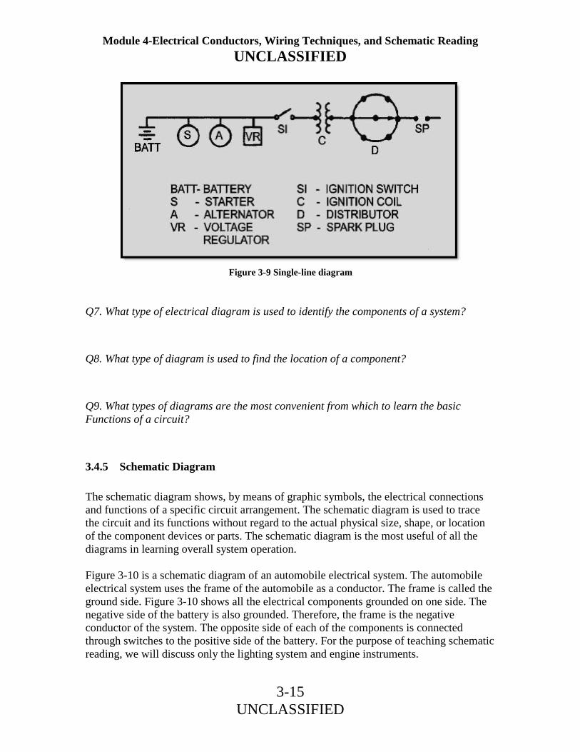
Module 4-Electrical Conductors, Wiring Techniques, and Schematic Reading UNCLASSIFIED
3-15 UNCLASSIFIED
Q7. What type of electrical diagram is used to identify the components of a system?
Q8. What type of diagram is used to find the location of a component?
Q9. What types of diagrams are the most convenient from which to learn the basic Functions of a circuit?
3.4.5 Schematic Diagram
The schematic diagram shows, by means of graphic symbols, the electrical connections and functions of a specific circuit arrangement. The schematic diagram is used to trace the circuit and its functions without regard to the actual physical size, shape, or location of the component devices or parts. The schematic diagram is the most useful of all the diagrams in learning overall system operation. Figure 3-10 is a schematic diagram of an automobile electrical system. The automobile electrical system uses the frame of the automobile as a conductor. The frame is called the ground side. Figure 3-10 shows all the electrical components grounded on one side. The negative side of the battery is also grounded. Therefore, the frame is the negative conductor of the system. The opposite side of each of the components is connected through switches to the positive side of the battery. For the purpose of teaching schematic reading, we will discuss only the lighting system and engine instruments.
Figure 3-9 Single-line diagram

Module 4-Electrical Conductors, Wiring Techniques, and Schematic Reading UNCLASSIFIED
3-16 UNCLASSIFIED
Figure 3-10 Schematic diagram

Module 4-Electrical Conductors, Wiring Techniques, and Schematic Reading UNCLASSIFIED
3-17 UNCLASSIFIED
The positive side of the 12-volt battery is connected to the starter solenoid, then to terminal B of the voltage regulator, and then down to point (1). (It should be noted that points (1), (2), (3), and so on, normally are not indicated on the schematic. They are shown here only to help you follow the diagram.) Therefore, if no faults are in the system, point (1) has a 12-volt positive potential at all times. This positive potential can be traced through the fuse to the OFF position of the light switch. The dashed line indicates the mechanical linkage of the switch. When the switch is pulled to the first position (park), +12 volts are applied to point (2). It can now be seen that the tail lights (T), the tag light, the side panel lights, and the instrument lights have +12 volts applied. The opposite side of each light is grounded. The instrument panel lights are grounded through the dimming rheostat. This completes the path for current flow from the negative side of the battery, through all the light bulbs (lamps), back to the positive side of the battery. If no faults exist, the lamps will light. When the light switch is pulled to the next position (on), the bar on the switch contacts the "off," "park," and "on" contacts of the switch. The lights that were illuminated before are still on, and the + 12 volt potential is now applied to the bright (B) side of the headlights through the dimmer switch. Since the headlights are also grounded on one side, there is now a complete path for current flow, and the headlights also light. If the dimmer switch is actuated, the positive potential is switched from the bright filament to the dim filament of the headlights, and the lights dim. The brake-light switch has +12 volts applied from point (1), directly to the stop lights (not fused). If the brake pedal is pressed, the switch is actuated, and the +12 volts are applied to both stop lights (S). Because one side of each light is tied to ground, there is a path for current flow, and the lights will light. If the dimming rheostat for the instrument lights is turned in the direction that increases the resistance, more voltage is dropped across the rheostat, less across the lights, and the lights will get dimmer. The +12 volts at point (1) are also supplied to the OFF position of the ignition switch. When the ignition switch is turned on, the +12 volts are felt at point (3). This is a common point to all the engine instruments. The gas gauge is a galvanometer with the dial graduated according to the amount of fuel in the tank. The gas gauge tank unit is a rheostat mechanically linked to a float in the gas tank. When the tank is full, the float rises to its highest level and positions the movable arm of the rheostat to a position of minimum resistance. This allows maximum current flow through the galvanometer, and the dial rests at the "full" mark on the gas gauge. As fuel is used by the engine, the float lowers, increasing the resistance of the rheostat to ground. This reduces the current through the galvanometer, and the dial shows a lesser amount of fuel.

Module 4-Electrical Conductors, Wiring Techniques, and Schematic Reading UNCLASSIFIED
3-18 UNCLASSIFIED
The oil-pressure light gets its ground through a normally closed pressure switch. (When no pressure is applied, the switch is closed.) When the engine is started, the oil pressure increases and opens the switch. This turns the light off by removing the ground. The water-temperature gauge is a galvanometer like the gas gauge, except its dial is graduated in degrees of temperature. The water-temperature element is a thermistor with a negative temperature coefficient. (A thermistor is a semiconductor device whose resistance varies with temperature.) When the engine is cold, the resistance of the thermistor is at a maximum. This reduces the current through the galvanometer, and a low temperature is indicated on the dial. As the water temperature of the engine increases, the resistance of the thermistor decreases. This allows more current to flow from ground through the galvanometer, and the temperature on the dial shows an increase. On the voltage regulator shown, the "T" terminal is grounded anytime the alternator does not have an output. This gives the alternator light a ground and causes it to illuminate. Q10. What type of diagram is the most useful in learning the overall operation of a system?
Q11. Refer to the schematic diagram in figure 3-10. If the ignition switch is placed in the ON position and all the engine instruments operate properly except the gas gauge, where would the fault probably be?
Q12. If the fuse shown on the schematic (figure 3-10) opens, what lights will operate?

Module 4-Electrical Conductors, Wiring Techniques, and Schematic Reading UNCLASSIFIED
3-19 UNCLASSIFIED
3.4.6 Wiring Diagram
A wiring diagram is a detailed diagram of each circuit installation showing all of the wiring, connectors, terminal boards, and electrical or electronic components of the circuit. It also identifies the wires by wire numbers or color coding. Wiring diagrams are necessary to troubleshoot and repair electrical or electronic circuits. The wiring diagram for an automobile is shown in figure 3-11. It shows all the electrical components and that the interconnecting wiring is color coded.
Figure 3-11 Wiring diagram

Module 4-Electrical Conductors, Wiring Techniques, and Schematic Reading UNCLASSIFIED
3-20 UNCLASSIFIED
You should use the schematic diagram previously discussed to determine where the trouble might be in the circuit when a malfunction occurs. The schematic diagram does not show the terminals, connector points, and so forth, of the circuit. Therefore, you must go to the circuit wiring diagram to determine where to make the voltage or resistance checks in the circuit when troubleshooting. Following is an example of how to use a schematic diagram in conjunction with a wiring diagram to troubleshoot a circuit. In the discussion of schematic diagrams, you will recall that when the light switch is pulled to the PARK position, the tail lights, side panel lights, tag light, and the instrument lights come on. Now, suppose that when the light switch is pulled to the PARK position all the lights come on, except the tag light. Referring to the schematic diagram (figure 3-10), you will recall that when the light switch is placed in the PARK position, +12 volts are applied to point (2). If all the lights come on except the tag light, then the fault must be between point (2) and the tag light ground. On the schematic shown in figure 3-11, you can see that there are numerous connections to point (2). Point (2) on the wiring diagram is actually composed of three different functions: terminal 1 of TB 1 (the head lamp junction block), terminals 1 and 2 of TB2 (the tail lamp junction block), and the "T" terminal of the light switch; all correspond to point (2) on the schematic. The fault here is in the tag light, which normally receives its +12 volts from terminal 1 of TB2. To use a voltmeter to find the fault, place the positive lead of the voltmeter to the ground terminal of the tag light and the negative lead to the frame. The voltmeter should read zero, because there should be no difference of potential between the two points. If the meter reads a voltage, the ground lead is either open or has a high-resistance connection. If the meter reads zero, as it should, you will have to go to another test point. In this case, place the positive voltmeter lead on the positive terminal of the tail light. If the voltmeter reads +12 volts, the light bulb is probably burned out or the light socket is defective. If the voltmeter reads zero, then the open is between terminal 1 of TB2 and the light.

Module 4-Electrical Conductors, Wiring Techniques, and Schematic Reading UNCLASSIFIED
3-21 UNCLASSIFIED
3.4.7 Terminal Diagram
A terminal diagram is useful when connecting wires to terminal boards, relays, switches, and other components of a circuit. Figure 3-12 shows two typical terminal diagrams. View A of the figure shows the wire numbers connected to each terminal of a terminal board. View B shows the different color codes of the wires that are connected to a relay. This has been a brief overview of the use and interpretation of electrical diagrams. The diagrams used were selected because of their simplicity and ease of interpretation. Many diagrams you will encounter are far more complex. Start with the simpler diagrams you will be working with on the job. Your proficiency in using the more complex diagrams will increase with experience and study.
Figure 3-12 Terminal diagrams

Module 4-Electrical Conductors, Wiring Techniques, and Schematic Reading UNCLASSIFIED
3-22 UNCLASSIFIED
Q13. What type of diagram is the most detailed?
Q14. Why must a wiring diagram be used in conjunction with a schematic to troubleshoot a system?
Q15. What type of diagram would be most useful for wiring a relay into a circuit?
3.5 SAFETY
The Secretary of the Navy, in establishing a Department of the Navy safety program, stressed, "Safety is an inherent responsibility of command...." He further outlined that, "Assignment of safety responsibility at all echelons of command is a basic requirement." This means responsibility right down through the lowest rated personnel in the command. Most noncombat accidents can be prevented if all personnel cooperate in eliminating unsafe conditions and acts. To this end, each individual is responsible for understanding and applying safety rules, standards, and regulations in all activities. Safety consciousness will help prevent personal injury and damage to property. Some safety precautions applicable to this module deal with fumes from synthetic insulation, breathing asbestos fibers, and working around/with electrical and electronic circuits and portable power tools. 3.5.1 Synthetic Insulation
Almost without exception, the fumes from synthetic materials, such as plastics in high-temperature environments, are objectionable from the standpoint of health and safety. Fluoroplastics (FEP and polytetrafluoroethylene) resist decomposition at higher temperature better than most other plastics. Exposure to fumes when working with fluoroplastics may cause a temporary flu-like condition similar to the metal fume fever (or "foundryman's fever"). These symptoms are commonly called polymer fume fever. They do not ordinarily occur until several hours after exposure, and pass within 36 to 48 hours, even in the absence of treatment. One of the largest uses of fluoroplastics is as a wire and cable insulation. When insulated wiring is installed, soldering is a routine fabricating procedure, as is the use of a heated element to remove insulation. In neither of these operations do the combined effects of temperature, quantity of resin, and exposure time produce toxic conditions of significance, as long as normal ventilation is maintained.

Module 4-Electrical Conductors, Wiring Techniques, and Schematic Reading UNCLASSIFIED
3-23 UNCLASSIFIED
Any special practices or precautions that may be required should follow the same common sense rules that apply to all soldering jobs. Prolonged soldering in confined spaces with restricted air circulation will require some ventilation for personal comfort. The same is true for open shop areas where a number of personnel are engaged in soldering or hot-wire stripping. Normal ventilation for personal comfort usually provides adequate safety. However, it is recommended that a small duct fan or "elephant trunk" exhaust be used at the workbench during soldering or wire stripping to carry away any toxic vapors. 3.5.2 Asbestos
Although asbestos-free products have been developed, older products containing asbestos materials still exist and continue to be used in the Navy. One such product is asbestos insulation used on wiring in high-temperature areas aboard ships and in aircraft. Because of the serious health hazards of asbestos exposure, the government has imposed strict occupational health and environmental protection standards for the control of asbestos. These standards must be strictly enforced and followed by all Navy personnel. Asbestos is a general term used to describe several fibrous mineral silicates. Major uses of asbestos include asbestos cement products, floor tiles, fireproofing, high-temperature insulation, asbestos cloth, friction materials (such as brake linings and clutch facings), various gasket materials, and miscellaneous other products. Inhaling asbestos fibers can produce disabling or fatal fibrosis of the lungs. Fibrosis of the lungs (asbestos) comes from inhaling asbestos fibers. Asbestos is a factor in the development of lung cancer as well as cancer of the gastrointestinal tract. It may take 20 to 40 years between initial exposure to asbestos and the appearance of a cancerous condition. Know where asbestos is in your environment and avoid or take precautions to prevent exposure.

Module 4-Electrical Conductors, Wiring Techniques, and Schematic Reading UNCLASSIFIED
3-24 UNCLASSIFIED
3.5.3 Electrical or Electronic Circuits and Portable Power Tools
When working on electrical or electronic circuits, you must observe certain general precautions. The following is a listing of common sense safety precautions that you must observe at all times:
• Remember that electrical and electronic circuits often have more than one source of power. Take time to study the schematics or wiring diagrams of the entire system to ensure that all power sources are deactivated.
• Remove all metal objects from your person. • Use one hand when turning switches on or off. Keep the doors to switch and fuse
boxes closed, except when working inside or replacing fuses. • After first making certain that the circuit is dead, use a fuse puller (figure 3-13) to
remove cartridge fuses.
Figure 3-13 Fuse puller

Module 4-Electrical Conductors, Wiring Techniques, and Schematic Reading UNCLASSIFIED
3-25 UNCLASSIFIED
• All supply switches or cutout switches from which power could possibly be fed should be secured in the OFF or OPEN (safety) position and tagged (figure 3-14). The tagging procedures must be done in accordance with the appropriate manual or instruction for your field of training.
Figure 3-14 DANGER tag

Module 4-Electrical Conductors, Wiring Techniques, and Schematic Reading UNCLASSIFIED
3-26 UNCLASSIFIED
• Keep clothing, hands, and feet dry if possible. When it is necessary to work in wet or damp locations, use a dry platform or wooden stool to sit or stand on, and place a rubber mat or other nonconductive material on top of the wood. Use insulated tools and molded insulated flashlights when you are required to work on exposed parts. In all instances, repairs on energized circuits must not be made with the primary power applied, except in an emergency, and then only after specific approval has been given by your commanding officer. When approval has been obtained to work on equipment with the power applied, keep one hand free at all times (BEHIND YOU OR IN YOUR POCKET).
• Never short out, tamper with, or block open an interlock switch. • Keep clear of exposed equipment; when it is necessary to work on it, work with
one hand as much as possible. • Avoid reaching into enclosures, except when it is absolutely necessary. When
reaching into an enclosure, use rubber blankets to prevent accidental contact with the enclosure.
• Make certain that equipment is properly grounded. • Turn off the power before connecting alligator clips to any circuit. • Never use your finger to test a "hot" line. Use approved voltmeters or other
voltage-indicating devices. 3.5.3.1 High Voltage Precautions
In addition to observing the general precautions just discussed, you must observe the following additional precautions when working with high voltages:
• Do NOT work with high voltage by yourself; have another person (safety observer), qualified in first aid for electrical shock, present at all times. This individual, stationed nearby, should also know the circuits and location of the switches controlling the equipment, and should be given instructions to pull the switch immediately if anything unforeseen happens.
• Always be aware of the nearness of high-voltage lines or circuits. Use rubber gloves where applicable and stand on approved rubber matting. Not all so-called rubber mats are good insulators.
• Always discharge the high voltage from components or terminals by using a safety probe.
• Do NOT hold the test probe when circuits over 300 volts are tested.

Module 4-Electrical Conductors, Wiring Techniques, and Schematic Reading UNCLASSIFIED
3-27 UNCLASSIFIED
3.5.3.2 Soldering Irons
When using a soldering iron, always keep in mind the following precautions and procedures:
• To avoid burns, ALWAYS ASSUME that a soldering iron is hot. • Never rest a heated iron anywhere but on a metal surface or rack provided for this
purpose. Faulty action on your part could result in fire, extensive equipment damage, and serious injuries.
• Never use an excessive amount of solder, since drippings may cause serious skin or eye burns.
• Do not swing an iron to remove excess solder. Bits of hot solder that are removed in this manner can cause serious skin or eye burns. Hot solder may also ignite combustible materials in the work area.
• When cleaning an iron, use a cleaning cloth, but DO NOT hold the cleaning cloth in your hand. Always place the cloth on a suitable surface and wipe the iron across it to prevent burning your hand.
• Hold small soldering jobs with pliers or a suitable clamping device to avoid burns. Never hold the work in your hand.
• Do not use an iron that has a frayed cord or damaged plug. • Do not solder components unless the equipment is disconnected from the power
supply circuit. Serious burns or death can result from contact with a high voltage. • After completing the task requiring the use of soldering iron, disconnect the
power cord from the receptacle and, when the iron has cooled, stow it in its assigned storage area.

Module 4-Electrical Conductors, Wiring Techniques, and Schematic Reading UNCLASSIFIED
3-28 UNCLASSIFIED
3.5.3.3 Portable Electric Power Tools
Navy specifications for portable electric power tools require that the electric cord of each tool have a distinctively marked ground wire in addition to the conductors for supplying power to the tool. (Double-insulated portable electric tools obtained from sources qualified under the applicable military specification are exempt from this grounding requirement.) The end of the ground wire within the tool must be connected to the metal housing of the tool. The other end must be connected to a positive ground. For this ground connection, specifically designed ground-type plugs and receptacles, which automatically make this connection when the plug is inserted into the receptacle, must be used. These grounded-type receptacles must be installed for all power outlets. When installed, they must be used with the grounded-type plugs to ground portable tools and equipment. If grounded-type receptacles have not yet been installed, they must be installed as soon as possible. Portable tools not provided with the ground-type plug, and miscellaneous portable electric equipment that does not have a cord with a ground conductor and grounded plug, must be given a three-conductor cord with a standard Navy grounded-type plug. The ground wire must be connected to a positive ground. Care must be exercised in connecting the plugs and cords. The grounding conductor of the cord must be connected to the ground contact of the plug at one end and to the metal equipment housing at the other end. The cord must be arranged so as not to create a tripping hazard. If the conductor connected to the metallic equipment housing is inadvertently connected to a line contact of the plug, a dangerous potential would be placed on the equipment casing. This could result in a fatal shock to the operator. If the cord is pulled loose from the plug, only a qualified electrician is authorized to repair it. If the grounded-type plugs and receptacles have not been installed in the spaces where a portable tool is to be used, other types of plugs and receptacles may be used only if a separate ground wire is connected between the tool housing and a positive ground. When the tool cord does not include an extra wire for grounding, an additional insulated wire should be connected between the metal housing of the tool and ground. If the tool housing has two or more conducting parts that are not electrically connected, each part must be connected to the ground wire. Connection of the ground wire to the tool housing and to the ground must be by means of screws or bolts. The use of spring clips for either end of the grounding wire is prohibited.

Module 4-Electrical Conductors, Wiring Techniques, and Schematic Reading UNCLASSIFIED
3-29 UNCLASSIFIED
When the ground connection is to be made by means other than a contact in the plug and receptacle, care must be taken to secure a good contact between the ground wire and the metal by scraping away paint from the metal to ensure a clean surface. The ground connection must be made before inserting the power supply connecting plug, and the plug must be pulled out before removing the ground connection. Frequent inspections of each of the connections of a portable electric tool must be made to ensure that the supply cord and its connections within the tool are suitably insulated and that the ground connection is intact. The safety precautions just discussed are to protect you and your shipmates. Follow safety precautions to the letter. DO NOT TAKE CHANCES. Carelessness could cost you your life. Q16. What safety precaution must you observe when soldering or hot-wire stripping fluoroplastic-insulated wire?
Q17. What must be used to test an activated circuit?
Q18. How should excess solder be removed from a hot soldering iron?

Module 4-Electrical Conductors, Wiring Techniques, and Schematic Reading UNCLASSIFIED
3-30 UNCLASSIFIED
3.6 SUMMARY
In this chapter, we have discussed some typical cable- and wire-marking systems, electrical diagrams, and some basic safety precautions. A brief summary of these subjects follows: Cable- and Wire-Marking Systems - Cables and wires must be identified to provide the technician with a means of tracing them when troubleshooting and repairing electrical and electronic systems. The cable and wire-marking systems discussed in this chapter are typical systems. The number of systems used throughout the Navy is too numerous to discuss. For the cable or wire identification for a specific piece of equipment, consult the technical manual for that equipment. One wire identification system you will surely come in contact with is the color coding of wires used on electrical power tools and appliances. Remember, the purpose of the green conductor in a power tool or appliance cable is to prevent electrical shock to the operator in case there is an electrical short to the frame of the appliance or tool. Pictorial Diagram - shows a picture or sketch of the various components of a system and the wiring between the components. Isometric Diagram - shows the outline of a ship, airplane, or piece of equipment. This diagram shows the components and the cable runs between the components. This diagram is used to locate components in a system. Block Diagram - shows the components in block form. Block diagrams are used in conjunction with text material. They are used to present a general description of a system and its functions. Single-Line Diagram - used for essentially the same purpose as the block diagram-to show the basic functions of a circuit. Schematic Diagram - shows, through graphic symbols, the electrical connections and functions of a specific circuit arrangement. It is used to trace the circuit without regard to the physical size, shape, or location of the component devices or parts. A schematic diagram shows the overall operation of a system. It is used during troubleshooting to identify possible circuit malfunction locations. Wiring Diagram - is a detailed diagram of each circuit installation showing all wiring, connectors, terminal boards, and the electrical or electronic components of the circuit. It also identifies the wire-by-wire numbers or color coding. This diagram must be used in conjunction with a schematic diagram to troubleshoot a system in order to find the test point for voltage and resistance checks. Terminal Diagram - is used in connecting wiring to terminal boards, relays, switches, and other components of a circuit.

Module 4-Electrical Conductors, Wiring Techniques, and Schematic Reading UNCLASSIFIED
3-31 UNCLASSIFIED
Safety - all individuals are responsible for understanding and complying with safety standards and regulations established to prevent injury to themselves and others and damage to property and equipment. Having safe working habits and adhering to safety precautions protects YOU and YOUR SHIPMATES. Follow safety precautions to the letter. DO NOT TAKE CHANCES. Carelessness could cost you your life.

Module 4-Electrical Conductors, Wiring Techniques, and Schematic Reading UNCLASSIFIED
3-32 UNCLASSIFIED
ANSWERS TO QUESTIONS Q1. THROUGH Q18. A1. To provide the technician with a means to trace the wires when troubleshooting and repairing electrical and electronic systems. A2. In the technical manual for the equipment. A3. Individual cable in a specific circuit. A4. Wire segment letter. A5. The conductor connections both "to" and "from." A6. To prevent electrical shock to the operator in case there is an electrical short to the frame of the appliance or too. A7. A pictorial diagram. A8. An isometric diagram. A9. Block or single-line diagram. A10. A schematic diagram. A11. Between point (3) and the gas gauge tank unit ground. A12. Only the brake lights. A13. Wiring diagram. A14. To find the test points. A15. Terminal diagram. A16. Adequate ventilation. A17. Approved meters or other indicating devices. A18. By use of a cleaning cloth.

Module 4-Electrical Conductors, Wiring Techniques, and Schematic Reading UNCLASSIFIED
A-1 UNCLASSIFIED
APPENDIX A Glossary ALUMINUM CREEP - The movement of aluminum wire away from a point where pressure is applied. (2) The retreat of heated aluminum wire as it cools. AMBIENT TEMPERATURE - The "surrounding temperature" - as the temperature surrounding a conductor in a compartment or within a piece of equipment. AMERICAN WIRE GAUGE (AWG) - The standards adopted in the United States for the measurement of wire sizes. ANTISEIZE COMPOUND - A silicon-based, high-temperature lubricant applied to threaded components to facilitate their removal after being subjected to rapid heating and cooling. ASBESTOS - A fiber-like mineral, noncombustible and nonconductive, used as an insulating material. BLOCK DIAGRAM - A diagram in which the major components of a piece of equipment or of a system are represented by squares, rectangles, or other geometric figures, and the normal flow of a signal or current is represented by lines. BRAID - The weaving of metal or cloth material as an outer coating to a cable; prevents cable damage from moisture and rough treatment. BRANCH - An individual current path in a parallel circuit. BUS BAR - A heavy cooper strap or bar used to connect several circuits together when a large current-carrying capacity is required. CABLE - Either a stranded conductor (single-conductor cable) or a combination of conductors insulated from one another (multiple-conductor cable). Small cable sizes are called stranded wire or cords. CENTIMETER CUBE - A unit of volume for large rectangular or square conductors. The cross-sectional area equals 1 square centimeter with a length of 1 centimeter. CIRCULAR MIL - The area of a circle having a diameter of 1 mil. The standard unit of measurement of wire cross-sectional area. One circular mil equals .7854 square miles.

Module 4-Electrical Conductors, Wiring Techniques, and Schematic Reading UNCLASSIFIED
A-2 UNCLASSIFIED
CIRCULAR-MIL-FOOT - A unit of volume of a conductor having a cross-sectional area of 1 circular mil and a length of 1 foot. COAXIAL CABLE - A cable made up of a center conductor separated from an outer conductor by a dielectric material. Normally used for radio-frequency transmission. COMPRESSED AIR/NITROGEN HEATING TOOL - A portable source of heat for use with heat-shrinkable products. CONDUIT - A tubular raceway, usually metal or plastic, for enclosing wires or cables. CONDUCTANCE - The ability of a material to conduct or carry an electric current. It is the reciprocal of the resistance of the material. CORONA - The discharge of electricity from a conductor with a high potential. CURRENT RATING - The safe current-carrying capacity of a wire or cable on a continuous basis. DIELECTRIC STRENGTH - The ability of an insulator to withstand a potential difference without breaking down. (Usually expressed in terms of voltage). DUCTILE - Easily drawn out-as to form filaments or wires. ELECTRICAL SYMBOLS - Graphic symbols used to illustrate the various electrical or electronic components of a circuit. ELECTROLYSIS - The process of changing the chemical composition of a material by passing an electric current through it. ELECTROSTATIC STRESS - The force exerted on an insulator by the voltage in a conductor. ENAMEL - Synthetic compound of cellulose acetate (wood pulp and magnesium). Used to insulate wire in meters, relays, and motor windings. EXTRUDED POLYTETRAFLUOROETHYLENE - A high-temperature insulation used extensively in aircraft and equipment installations. (Emits dangerous fumes when heated.) FEP Fluorinated Ethylene Propylene) - A synthetic type of insulation. FIBROUS BRAID - An outer covering used to protect the insulating material of a conductor. Commonly made from cotton, linen, silk, rayon, or fiberglass.

Module 4-Electrical Conductors, Wiring Techniques, and Schematic Reading UNCLASSIFIED
A-3 UNCLASSIFIED
FLUX - A material that removes oxides from surfaces to be joined by soldering or welding. GALVANOMETER - A meter used to measure small values of current by electromagnetic or electrodynamics means. HEAT-SHRINKABLE TUBING - A plastic tube that, when heated, shrinks to encapsulate, protect, or insulate connections, splices, terminations, and other configurations. HEAT SHUNT - A device (preferably a clip-on type) used to absorb heat and protect heat-sensitive components during soldering. INSULATION - Materials used to coat or wrap conductors to prevent current leakage. INSULATION RESISTANCE - The resistance offered by an insulating material to current leakage. ISOMETRIC DIAGRAM - A diagram showing the outline of a ship or aircraft or equipment, and the location of equipment and cable runs. JUNCTION BOX - A box with a cover for joining different runs of wire or cable and for providing space for the connection and branching of the enclosed conductors. LACING SHUTTLE - A device upon which lacing may be wound to prevent fouling the tape or cord and facilitate the lacing process. (Usually made from brass, aluminum, fiber, or plastic.) LEAD SHEATH - A continuous jacket of lead molded around a single-conductor or multiple-conductor cable. Generally used to ensure that conductors are protected from water or extensive moisture. MAGNET WIRE - Wire coated with an enamel insulation and used in coils, relays, transformers, motor windings, and so forth. METALLIC ARMOR - A protective covering for wires or cables. Made as a woven wire braid, metal tape, or interlocking metal cover. Made from steel, copper, bronze, or aluminum. MIL - The diameter of a conductor equal to 1/1000th (.001) inch. MIL-FOOT - A unit of measurement for conductors. (Diameter of 1 mil, 1 foot in length.)

Module 4-Electrical Conductors, Wiring Techniques, and Schematic Reading UNCLASSIFIED
A-4 UNCLASSIFIED
MILITARY SPECIFICATIONS (MIL-SPEC) - Technical requirements and standards adopted by the Department of Defense, which are to be met by vendors selling materials to DOD. MULTICONDUCTOR - More than one conductor. NEGATIVE TEMPERATURE COEFFICIENT - The temperature coefficient expressing the amount or reduction in the value of a quantity, such as resistance for each degree of increase in temperature. OXIDATION - The addition of atmospheric oxygen to metal to form rust, or to cause a breakdown in the internal construction of the metal. PETROLEUM ABRASIVE COMPOUND - A compound that causes a grinding action during the crimping operation and removes the oxide film from the aluminum. PICTORIAL DIAGRAM - A diagram showing pictorial sketches of the parts of a piece of equipment and the electrical connections between the parts. POWER LOSS - The electrical power supplied to a circuit that does no work, usually dissipated as heat. RECEPTIVITY - The reciprocal of conductivity. (See also SPECIFIC RESISTANCE.) RHEOSTAT - (1) A resistor whose value can be varied. (2) A variable resistor used to adjust the current in a circuit. RHO - Greek letter “rho” (ρ). Used in electricity to represent the specific resistance of a substance. SCHEMATIC - A diagram that shows, in graphic symbols, the electrical connections and functions of a specific circuit arrangement. The schematic diagram makes tracing the circuit and its functions easier without regard to the physical size, shape, or location of the component device or parts. SINGLE-LINE DIAGRAM - A diagram that shows, in single lines and graphic symbols, the course of an electric circuit or system of circuits and the component devices or parts used in the circuit(s). SOLDERING - The joining of metals with a higher melting point than solder. SPAGHETTI TUBING - (See TRANSPARENT TUBING.)

Module 4-Electrical Conductors, Wiring Techniques, and Schematic Reading UNCLASSIFIED
A-5 UNCLASSIFIED
SPECIFIC RESISTANCE - The resistance, measured in ohms, of a unit volume of a substance to the flow of electric current. (The unit volume used is generally the Circular-Mil-Foot.) SPLICE - A joint formed by connecting two or more conductors. SQUARE MIL - The area of a square, the sides of which are each equal to 1 mil. One square mil is equal to 1.2732 circular mils. STRANDED CONDUCTOR - A conductor composed of a group of wires. The wires in a stranded conductor are usually twisted together and not insulated from each other. STRANDS - Fine metallic filaments twisted together to form a single wire. TEMPERATURE COEFFICIENT OF RESISTANCE - The amount of increase in the resistance of a 1-ohm sample of a conductor per each degree of rise in temperature above 0º C. TENSILE STRENGTH - The greatest stress a substance can withstand along its length without tearing apart. TERMINAL - A point of connection for two or more conductors in an electrical circuit. TERMINAL BOARD - (Also called a terminal strip.) An insulating base or slab equipped with terminals for connecting wiring. TERMINAL DIAGRAM - A diagram of a switch, relay, terminal board, or other component showing the connections to the equipment. TERMINAL LUG - A device attached to a conductor for connecting to a terminal. THERMAL INERTIA - The capacity of a soldering iron to generate and maintain a satisfactory soldering temperature while giving up heat to the material being soldered. THERMISTOR - A semiconductor device whose resistance varies with temperature. THERMOPLASTIC - A synthetic mixture of rosins that is flexible and used as an insulating material. Generally used as an insulator for low- and medium-range voltages. TINNING - The process of applying a thin coat of solder to materials prior to their being soldered (for example, application of a light coat of solder to the filaments of a conductor to hold the filaments in place prior to soldering the conductor).

Module 4-Electrical Conductors, Wiring Techniques, and Schematic Reading UNCLASSIFIED
A-6 UNCLASSIFIED
TOXIC VAPORS - Vapors emitted by a substance that can do bodily harm. TRANSPARENT TUBING - (Also known as spaghetti tubing.) A plastic tubing used for insulation and wire marking. UNIT SIZE - The standards adopted to make comparisons between things of like value (for example, the unit size for conductors is the mil-foot). VARNISHED CAMBRIC - Cotton cloth coated with insulation varnish. An insulation used on high-voltage conductors. VOLTAGE DROP - The difference in voltage between two points. It is the result of the loss of electrical pressure as a current flows through a resistance. WIRE - A solid or stranded group of solid, cylindrical conductors having low resistance to current flow, with an associated insulation. WIRE STRIPPERS - A tool used to strip insulation from wire. WIRING DIAGRAM - A diagram that shows the connections for an installation or for its component devices or parts. The diagram may show internal or external connections, or both, and also show the details needed to make or trace the connections involved.

Module 4-Electrical Conductors, Wiring Techniques, and Schematic Reading UNCLASSIFIED
B-1 UNCLASSIFIED
APPENDIX B Electrical and Electronic Symbols

Module 4-Electrical Conductors, Wiring Techniques, and Schematic Reading UNCLASSIFIED
B-2 UNCLASSIFIED

Module 4-Electrical Conductors, Wiring Techniques, and Schematic Reading UNCLASSIFIED
C-1 UNCLASSIFIED
APPENDIX C References NOTE: Although the following references were current when this TRAMAN was published, their continued currency cannot be assured. Therefore, you need to ensure that you are studying the latest revision. Aircraft Electric and Electronic Wiring, NAVAIR 01-1A-505, Naval Air Systems Command, Washington, DC, June 1988. Dictionary of Standard Terminal Designations for Electronic Equipment, NAVSEA 0967-LP-146-0010, Bureau of Ships, Washington DC, March 1954 Electronic Installation and Maintenance Book, NAVSEA 0967-LP-000-0110, Naval Sea Systems Command, Washington, DC, September 1977. National Electrical Code, National Fire Protection Association, Battery March Park, Quincy, MD, 1990. Navy Occupational Safety and Health (NAVOSH) Program Manual, SPAWARINST 5100.9C, Space and Naval Warfare Systems Command, June 1987. Subsystem Design and Engineering Standards for Common Long Haul/Tactical Cable and Wire Communications, MIL-STD-188-112, Department of Defense, Washington, DC, August 1983.

Module 4-Electrical Conductors, Wiring Techniques, and Schematic Reading UNCLASSIFIED
1 UNCLASSIFIED
ASSIGNMENT 1 Textbook Assignment: Chapter 1, “Electrical Conductors,” pages 1-1 through 1-43. Chapter 2 “Wiring Techniques,” pages 2-1 through 2-33. 1-1. Why has a "unit size" for conductors been established?
1. To compare the size and resistance of one conductor with that of another 2. To establish a uniform style for conductors 3. To determine the requirements for conductors 4. To ensure all conductors are interchangeable
1-2. What is the decimal equivalent of one (1) mil?
1. 1.000 in. 2. 0.100 in. 3. 0.010 in. 4. 0.001 in.
1-3. If a conductor has a diameter of 1/4 inch, what is its diameter in mils?
1. 250.0 mil 2. 25.0 mil 3. 2.50 mil 4. 0.250 mil
1-4. What is the definition of a mil foot?
1. A conductor .001 foot in length with a diameter of .001 millimeter 2. A conductor 1 foot in length with a diameter of .001 foot 3. A conductor 1 foot in length with a diameter of 1 mil 4. A conductor .001 foot in length with a diameter of .001 inch
1-5. A square mil is defined as the area of a square, the sides of which are each equal
in length to what dimension?
1. 1 mil-foot 2. 1 mil 3. 1.0 inch 4. .001 mil

Module 4-Electrical Conductors, Wiring Techniques, and Schematic Reading UNCLASSIFIED
2 UNCLASSIFIED
IN ANSWERING QUESTION 1-6, REFER TO FIGURE 1A. 1-6. What is the cross-section area of the illustrated rectangular bar conductor in square mils?
1. 937,500,000 sq. mil 2. 3,750,000 sq. mil 3. 1,250,000 sq. mil 4. 187,500 sq. mil
1-7. A circular mil is defined as the area of a circle having what dimension?
1. A radius of 1 mil 2. A diameter of 1 mil 3. A circumference of 1 mil 4. A chord of 1 mil
1-8. If you have a 12-strand conductor and each strand has a radius (one half the
diameter) of 2/10 inch, what is the circular mil area of the conductor?
1. 1,920,000 cir. mil 2. 57,680 cir. mil 3. 48,000 cir. mil 4. 2,400 cir. mil
Figure 1A Rectangular Bar Conductor

Module 4-Electrical Conductors, Wiring Techniques, and Schematic Reading UNCLASSIFIED
3 UNCLASSIFIED
1-9. What is the square mil area for the conductor explained in question 1-8?
1. 244,344,097 sq. mil 2. 1,507,965 sq. mil 3. 61,115 sq. mil 4. 45,239 sq. mil
1-10. What is the definition of specific resistance?
1. The resistance of a length of conductor, at a given temperature, to voltage 2. The resistance of a cross-sectional area of a conductor, at a given
temperature, to the flow of current 3. The resistance of a unit volume of a substance to the flow of current
expressed in ohms 1-11. What factor(s) must be known to compute the resistance of a conductor?
1. The length of the conductor 2. The cross-sectional area of the conductor 3. The specific resistance of the substance of the conductor 4. Each of the above

Module 4-Electrical Conductors, Wiring Techniques, and Schematic Reading UNCLASSIFIED
4 UNCLASSIFIED
REFER TO THE FOLLOWING INFORMATION AND USE FIGURE 1B TO ANSWER QUESTION 1-12. ASSUME THE TEMPERTURE TO BE 25º C AND YOU HAVE TWO NEW COPPER CONDUCTORS TO RUN. RUN NO. 1 IS TO BE 2500 FEET LONG USING NO. 12 WIRE. RUN NO. 2 IS TO BE 6000 FEET LONG USING NO. 7 WIRE. 1-12. What is the approximate total resistance of (a) Run No. 1 and (b) Run No. 2?
1. 9.72 ohms (b) 1.27 ohms 2. 4.68 ohms (b) 3.52 ohms 3. 4.05 ohms (b) 3.05 ohms 4. 1.12 ohms (b) 4.98 ohms
1-13. When a wire gauge is used to determine the size of a wire, the measurement
should be made in what part of the gauge?
1. In the slot 2. In the semicircular opening 3. Either 1 or 2 above, depending on wire size
Figure 1B

Module 4-Electrical Conductors, Wiring Techniques, and Schematic Reading UNCLASSIFIED
5 UNCLASSIFIED
IN ANSWERING QUESTION 1-14, REFER TO FIGURE 1C. 1-14. Which of the following factors is used to determine the current rating of a wire?
1. B, C, E, and G 2. A, D, E, and G 3. B, D, E, and F 4. A, B, E, and F
1-15. What types of insulation are best suited for use in a high-temperature
environment?
1. Cotton, polytetrafluoroethylene, and oiled paper 2. FEP, silicone rubber, and extruded polytetrafluoroethylene 3. Oiled paper, FEP, and rubber 4. Rubber, polytetrafluoroethylene, and silk
1-16. What is the "ambient" temperature of a conductor?
1. It is the normal temperature of a conductor through which current is flowing
2. It is the heat generated by external sources and affecting a conductor’s temperature
3. It is the maximum heat a conductor can withstand according to its current rating
4. It is the temperature at which the insulation of a conductor begins to break down
Figure 1C

Module 4-Electrical Conductors, Wiring Techniques, and Schematic Reading UNCLASSIFIED
6 UNCLASSIFIED
1-17. Which of the following metals is the best conductor of current?
1. Aluminum 2. Copper 3. Silver 4. Manganin
FIGURE 1D LISTS SOME OF THE ADVANTAGES AND DISADVANTAGES OF VARIOUS CONDUCTORS. IN ANSWERING QUESTIONS 1-18 AND 1-19, REFER TO FIGURE 1D. 1-18. When electricity is carried over long distances, which of the following are
advantages for using aluminum as the conductor as opposed to copper?
1. B and C 2. D and E 3. C and I 4. E and G
1-19. Which of the following are advantages for using copper as the conductor as
opposed to aluminum?
1. B, D, and I 2. C, E, and G 3. B, E, and H 4. A, F, and I
Figure 1D

Module 4-Electrical Conductors, Wiring Techniques, and Schematic Reading UNCLASSIFIED
7 UNCLASSIFIED
1-20. Because its resistance changes very little with temperature changes, what conductor is best suited for use in measuring instruments?
1. Copper 2. Aluminum 3. Manganin 4. Silver
1-21. If a 75-ohm sample of copper wire at 0º C is heated to 30º C, what is the
approximate total resistance? (The temperature coefficient of resistance of copper at 0º C is 0.00427).
1. 0.32 ohm 2. 9.61 ohms 3. 65.39 ohms 4. 84.61 ohms
1-22. What definition best describes an insulating material?
1. A material that has a very high resistance 2. A material that has a very low resistance 3. A material that has a very high conductivity 4. A material that has a very low dielectric strength
1-23. The dielectric strength of an insulating material is a measurement of the material's
ability to resist electrostatic stress caused by what factor?
1. Resistance 2. Current 3. Voltage 4. Chafing or friction
1-24. Insulation resistance can best be defined as the ability of an insulating material to
resist what action?
1. Current leakage 2. Electrostatic stress 3. Breakdown by voltage 4. External factors acting upon the conductor

Module 4-Electrical Conductors, Wiring Techniques, and Schematic Reading UNCLASSIFIED
8 UNCLASSIFIED
1-25. For a material to be a good insulator, what two properties are most important?
1. High dielectric strength and low insulation resistance 2. High dielectric strength and high insulation resistance 3. Low dielectric strength and high insulation resistance 4. Low dielectric strength and low insulation resistance
1-26. When rubber is used as the insulating material over a copper conductor, why is a
thin coating of tin used between the two materials?
1. To decrease the electrostatic stress 2. To increase the insulation resistance of the rubber 3. To prevent a chemical action from taking place between the copper and
rubber 4. To reduce the amount of insulating material required.
1-27. What is the NEC for a rubber heat-resistance compound?
1. RHH 2. RWH 3. RTW 4. RWT
1-28. Latex rubber is a high-grade compound consisting of what percentage of unmilled
grainless rubber?
1. 70% 2. 80% 3. 90% 4. 95%
1-29. Plastic insulation is normally used for what levels of voltage?
1. Very high to high 2. High to medium 3. Medium to low 4. Low to very low
1-30. When dealing with NEC type designators for thermoplastics, the letter "W" stands
for what type of insulation?
1. Oil-resistant 2. Moisture-resistant 3. Heat-resistant 4. Asbestos

Module 4-Electrical Conductors, Wiring Techniques, and Schematic Reading UNCLASSIFIED
9 UNCLASSIFIED
1-31. When you work on synthetic insulated wiring, what safety precaution must be observed?
1. Wear protective goggles at all times 2. Avoid breathing the vapors when the insulation is heated 3. Wear a dust mask in confined spaces 4. Wear protective gloves if there are cuts or abrasions on your hands
1-32. What nonmetallic material is most commonly used to protect wires and cables?
1. Rubber 2. Jute and asphalt covering 3. Fibrous tape 4. Fibrous braid
1-33. What is the common name for woven covers?
1. Yarn 2. Loom 3. Fibrous tape 4. Unspun felted cotton
1-34. What percentage of tin is used in alloy-lead sheathing?
1. 6% 2. 2% 3. 8% 4. 4%
1-35. Why is the use of asbestos being discontinued as an insulating material in the
Navy?
1. It breaks down rapidly with continued use 2. It is not as effective as other types of insulation 3. It has not proven suitable for a shipboard environment 4. It poses a health hazard to personnel
1-36. What happens to asbestos insulation when it gets wet?
1. Its insulation resistance becomes too high 2. It emits dangerous fumes 3. It acquires too great a dielectric strength 4. It becomes a conductor

Module 4-Electrical Conductors, Wiring Techniques, and Schematic Reading UNCLASSIFIED
10 UNCLASSIFIED
1-37. What insulating materials are best suited for use with high voltage?
1. Thermoplastic and rubber 2. Varnished cambric and oil impregnated paper 3. Teflon and silk 4. Silk and cotton
1-38. What is the common name for enamel-insulated wire?
1. Winding wire 2. Motor wire 3. Magnet wire 4. Coil wire
1-39. What types of conductor protection are normally used for shipboard wiring?
1. Wire braid armor and nonmagnetic steel tape 2. Lead cable and Jute 3. Jute and nonmagnetic steel tape 4. Lead sheathing and rubberized tape
1-40. What are the basic requirements for a splice or terminal connection?
1. To be mechanically and electrically effective 2. To be preinsulated and nonconductive 3. To have minimum cost and maximum efficiency 4. To have circuit continuity and minimum cost
1-41. The preferred method for removing insulation from most types of insulated wire
is by using what tool?
1. Razor blade 2. Electrician’s pliers 3. Wire stripper 4. Knife
1-42. When a wire is insulated with glass braid or asbestos and requires stripping,
which of the following tools should NOT be used?
1. Knife 2. Rotary wire stripper 3. Hand wire stripper 4. Hot-blade wire stripper

Module 4-Electrical Conductors, Wiring Techniques, and Schematic Reading UNCLASSIFIED
11 UNCLASSIFIED
1-43. What is the preferred tool to use to strip aluminum wire?
1. Knife 2. Rotary wire stripper 3. Hand wire stripper 4. Hot-blade wire stripper
1-44. When a Western Union splice is used to connect two wires, why should the
twisted ends of the wires be pressed down as close as possible to the straight portion of the wire?
1. To increase the strength of the splice 2. To prevent the wires from puncturing the tape covering 3. To minimize the resistance change in the circuit 4. To increase the dielectric strength of the insulation
1-45. When multiconductor cables are spliced, why are the splices staggered?
1. To prevent possible shorting between conductors 2. To increase the strength of the individual splices 3. To decrease insulated resistance 4. To reduce the overall size of the joint
1-46. When is a rattail joint normally used?
1. When a branch circuit is required and a junction box is used to join conduit
2. When a Western Union splice would be too bulky 3. When asbestos or glass braid is used as insulation 4. When the branch wire will be subjected to a heavy strain
1-47. If a fluorescent light is to be attached to a branch circuit, which of the following
splices should normally be used?
1. Staggered splice 2. Knotted tap joint 3. Western Union splice 4. Fixture joint

Module 4-Electrical Conductors, Wiring Techniques, and Schematic Reading UNCLASSIFIED
12 UNCLASSIFIED
1-48. When is a knotted tap joint normally used?
1. When a branch circuit is joined to a continuous wire (main wire) 2. When a Western Union splice would be too bulky 3. When a lighting fixture is joined to a branch circuit 4. When a wire nut is used to complete the joint
1-49. Which of the following splices is NOT butted?
1. Fixture joint 2. Rattail joint 3. Knotted tap joint 4. Western Union splice
1-50. Why is friction tape used over a splice?
1. To provide a protective covering over the rubber tape 2. To provide maximum insulation to the splice 3. To prevent shock when latex rubber is used 4. To reduce the amount of rubber tape required
1-51. Why would you use a crimped terminal instead of a soldered terminal?
1. Connections can be made more rapidly 2. Less operator skill is required 3. Connections are more uniform in construction 4. Each of the above
1-52. When noninsulated splices and terminal lugs are insulated, what types of
insulation are most commonly used?
1. Rubber tape and friction tape 2. Spaghetti and heat-shrinkable tubing 3. Spaghetti and friction tape 4. Rubber tape and heat shrinkable tubing
1-53. When heat-shrinkable tubing is used, what is the maximum temperature to which
the wire should be subjected?
1. 180ºF 2. 220ºF 3. 300ºF 4. 340ºF

Module 4-Electrical Conductors, Wiring Techniques, and Schematic Reading UNCLASSIFIED
13 UNCLASSIFIED
1-54. When a large aluminum terminal lug or splice is installed, why is it NOT necessary to clean the aluminum wire?
1. It is done automatically by the tubing 2. The wire is cleaned by the abrasive compound in the lug or splice 3. Oxide film does not form on aluminum 4. The insulation used provides the necessary cleaning agent
1-55. When aluminum terminals lugs or splices are installed, which of the following
tools is generally recommended for use?
1. Pliers 2. Power crimping tool 3. Hand crimping tool 4. Vise grips
1-56. Why is a lockwasher NOT used with an aluminum terminal?
1. The washer will reduce conductivity at the terminal 2. The washer will gouge the lug and cause deterioration 3. The washer will set up a corrosive action between dissimilar metals 4. The washer will increase resistance and heat causing eventual failure
1-57. The most common method of terminating and splicing wires is by using
preinsulated terminal lugs and splices.
1. True 2. False
1-58. Which of the following is an advantage of using preinsulated splices and terminal
lugs?
1. Heat shrinkable tubing is not required 2. Spaghetti is not required 3. They offer extra supporting strength to the wire insulation 4. Each of the above

Module 4-Electrical Conductors, Wiring Techniques, and Schematic Reading UNCLASSIFIED
14 UNCLASSIFIED
1-59. Color codes are used on preinsulated terminal lugs and splices to indicate what information?
1. The resistance, in ohms, of the lugs and splices 2. The style of crimping tool to be used 3. The type of circuit in which they are to be used 4. The wire sizes on which they are to be used

Module 4-Electrical Conductors, Wiring Techniques, and Schematic Reading UNCLASSIFIED
15 UNCLASSIFIED
ASSIGNMENT 2 Textbook assignment: Chapter 2, “Wiring Techniques,” pages 2-34 through 2-70. Chapter 3, “Schematic Reading,” pages 3-1 through 3-32. 2-1. Why must materials to be soldered be cleaned just prior to the soldering process?
1. To ensure the solder will adhere to the surface 2. To prevent the solder from becoming brittle from impurities and
eventually failing 3. To prevent an uneven flow of solder to the surface 4. Each of the above
2-2. What is meant by the term "tinning"?
1. Removing the oxide coating of the material to be soldered 2. Preheating the material to be soldered to remove any impurities left from
the stripped insulation 3. Coating the material to be soldered with a light coat of solder 4. Applying pure tin to the material to be soldered to ensure adherence of the
solder 2-3. When a wire is soldered to a connector, why should the wire be stripped
approximately 1/32 inch longer than the depth of the solder barrel?
1. To prevent burning the wire insulation 2. To allow the wire to flex more easily at stress points 3. Both 1 and 2 above 4. To prevent the flux from touching the insulation
2-4. When a wire has been properly stripped and is to be soldered to a connector, what
total length of the exposed wire should be tinned?
1. One-third 2. One-half 3. Two-thirds 4. The entire exposed length
2-5. What action generally causes a fractured solder joint?
1. Movement of the soldered parts during the cooling process 2. Application of too much heat to the parts 3. Introduction of impurities to the joint from dirty solder or flux 4. Application of too much solder to the joint

Module 4-Electrical Conductors, Wiring Techniques, and Schematic Reading UNCLASSIFIED
16 UNCLASSIFIED
2-6. What term defines the capacity of a soldering iron to generate and maintain a satisfactory soldering temperature while giving up heat to the joint being soldered?
1. Iron current flow 2. Thermal inertia 3. Resistance soldering 4. Self-regulating heat
2-7. Why should a small wattage soldering iron NOT be used to solder large
conductors?
1. The current flow is limited 2. The iron cannot reach a high enough temperature 3. The iron cannot maintain a satisfactory soldering temperature while giving
up heat to the conductor 4. The tip of a small wattage iron is too small for large conduct
2-8. Which of the following features BEST describes a well designed soldering iron?
1. It may be used for both large and miniature soldering jobs 2. It is light weight with an all-purpose tip 3. It can be automatically switched from a low wattage to a high wattage
output 4. 4.It has a built-in self-regulating element
2-9. What should be done with the removable tip of a soldering gun after it becomes
pitted?
1. Dip it in flux and continue to use it 2. Discard the tip and replace it 3. Grind the tip down to the next smaller size and reuse it 4. File the tip smooth and retin it
2-10. If, during the soldering process, the soldering gun switch is depressed for longer
than 30 seconds, what danger exists?
1. The insulation of the wire may be burned 2. An oxide film will rapidly form on the conductor 3. The flux may ignite 4. The finger switch may be locked in the depressed position from the heat

Module 4-Electrical Conductors, Wiring Techniques, and Schematic Reading UNCLASSIFIED
17 UNCLASSIFIED
2-11. What condition causes the nuts or screws which hold the tip of a soldering gun to loosen?
1. The trigger is depressed for too long a period 2. The gun is pulsed too often 3. The heating and cooling cycle loosens them 4. The gun is used for soldering items beyond its capacity
2-12. Which of the following electronic components should NOT be installed or
removed by the use of a soldering gun?
1. Transistors 2. Resistors 3. Capacitors 4. Each of the above
2-13. Why are resistance soldering irons safer for electrical equipment components than
other soldering irons or guns?
1. The current flow is very low 2. The tips are hot only during the brief period of actual soldering 3. The transformer provides a high voltage for a measured period of time 4. The tips are made from highly conductive ferrous iron which heat and cool
very rapidly 2-14. For which of the following reasons is antisieze compound used with a pencil iron
equipped with removable tips?
1. To allow the tip to be easily removed 2. To prevent the tip form loosening during repeated soldering operations 3. To minimize the number of times the tip must be retinned 4. Each of the above
2-15. If you do not have a suitable tip for desoldering, how can one be improvised?
1. File an available tip down to the desired size 2. Bend a piece of wire to the desired shape and insert the ends of the wire
into the barrel 3. Bend a piece of copper wire to the desired shape after wrapping it around
a regular tip 4. File a piece of round stock, preferably steel, to the desired shape and insert
it in the barrel

Module 4-Electrical Conductors, Wiring Techniques, and Schematic Reading UNCLASSIFIED
18 UNCLASSIFIED
2-16. What are the two metals most often used to form soft solder?
1. Lead and antimony 2. Tin and lead 3. Bismuth and tin 4. Tin and cadmium
2-17. What chemical or physical change causes a joint of soldered copper conductors to
become one common metal?
1. A physical change takes place as the solder flows between the molecules of copper joining them together when cooled
2. A physical change takes place as both metals displace one another 3. A chemical change takes place as the copper is dissolved into the solder
thereby forming an alloyed metal 4. A chemical change takes place when the additional materials added to the
solder are heated causing a gluing effect between the solder and the copper 2-18. When you solder electrical connectors, splices, and terminal lugs, what type of
solder should you use?
1. 65/35 solder 2. 63/37 solder 3. 60/40 solder 4. 57/43 solder
2-19. Why is flux used in the soldering process?
1. It dilutes the molten solder and allows it to flow 2. It acts as a cleaning agent to remove oxide 3. It acts as the bonding agent between the solder and metal 4. It forms a conductive bond between the metal and the solder
2-20. When electrical and electronic components are soldered, what type of flux must
be used?
1. Hydrochloric acid 2. Sal ammoniac 3. Zinc chloride 4. Rosin

Module 4-Electrical Conductors, Wiring Techniques, and Schematic Reading UNCLASSIFIED
19 UNCLASSIFIED
2-21. What two properties must a solvent have?
1. Noncorrosive-nonconductive 2. Corrosive-conductive 3. Noncorrosive-conductive 4. Corrosive-nonconductive
2-22. Why are solvents used in the soldering process?
1. To remove the flux from the metal surface being soldered 2. To remove contaminants from the soldered connection 3. To dilute the flux and allow it to flow freely 4. To improve the conductivity of the flux
2-23. Why are heat shunts used in the soldering process?
1. To conduct heat from the component being soldered back to the iron 2. To increase the temperature of the soldering iron or gun 3. To prevent damage to adjacent heat-sensitive components 4. To decrease the temperature to the conductor being soldered
2-24. For which of the following reasons are conductors laced together?
1. To present a neat appearance 2. To help support each other 3. To aid in tracing conductors 4. Each of the above
2-25. Although it may be used, why is the use of round cord discouraged for lacing
conductors?
1. It is bulkier than the flat type 2. It is more difficult to handle 3. It is not fungus resistant 4. It has a tendency to cut into wire insulation
2-26. If you are preparing to single lace conductors, what total length must the lacing be
in relationship to the longest conductor?
1. One and one-half times the length 2. Twice the length 3. Two and one-half times the length 4. Five times the length

Module 4-Electrical Conductors, Wiring Techniques, and Schematic Reading UNCLASSIFIED
20 UNCLASSIFIED
2-27. Why is a lacing shuttle used when conductors are laced in bundles?
1. It helps prevent the conductors from twisting together 2. It helps prevent the cord or tape from fouling 3. It keeps the "lay" of the cord or tape 4. It ensures that hitches are evenly spaced
2-28. Under certain circumstances, it is permissible to twist conductors together prior to
lacing.
1. True 2. False
2-29. When coaxial cables are laced, the use of round cord is prohibited. What
additional precaution must be observed?
1. Coaxial cables may not be laced with other conductors 2. Bundles containing coaxial cables must be double laced 3. Half hitches must be used in place of marling hitches 4. Coaxial cables must not be tied so tightly as to deform the dielectric
2-30. How should a single lace be started?
1. With a square knot and two marling hitches 2. With a marling hitch and a telephone hitch 3. With a telephone hitch and two half hitches 4. With a square knot and two half hitches
2-31. Under which of the following conditions should a double lace be used?
1. Three coaxial cables form the bundle 2. A maximum of six conductors form the bundle 3. The bundle is larger than one inch in diameter 4. The bundle exceeds 10 feet in length
2-32. How should a double lace be started?
1. With a square knot 2. With a half hitch 3. With a marling hitch 4. With a telephone hitch

Module 4-Electrical Conductors, Wiring Techniques, and Schematic Reading UNCLASSIFIED
21 UNCLASSIFIED
2-33. How should laced cable groups that run parallel to each other be bound together?
1. With marling hitches 2. With telephone hitches 3. With square knots 4. With half hitches
2-34. What tool or technique should be used to install self-clinching cable straps?
1. Military standard hand tool 2. Circle snips 3. Electrician’s pliers 4. Hand installation
2-35. If a bundle of conductors passes through a very high-temperature area, what
restraint should be used to tie the bundle?
1. High-temperature pressure-sensitive tape 2. Flat glass fiber tape 3. Self-clinching cable straps 4. Double lacing
2-36. Why do cables and wires require identification?
1. To assist the technician in troubleshooting a circuit 2. To assist the technician in making repairs 3. To permit the tracing of a circuit 4. Each of the above
2-37. Of the following publications, which should be used to determine the wire
identification system for a specific piece of equipment?
1. The damage control manual 2. The technical manual for the equipment 3. The maintenance material management manual 4. The illustrated parts breakdown of the equipment
2-38. What is the purpose of the green conductor in a power tool or electric appliance
cable?
1. To complete the circuit 2. To act as the "hot" lead 3. To prevent electrical shock to the operator 4. To prevent the motor of the unit from overloading

Module 4-Electrical Conductors, Wiring Techniques, and Schematic Reading UNCLASSIFIED
22 UNCLASSIFIED
IN ANSWERING QUESTIONS 2-39 THROUGH 2-45, REFER TO FIGURE 2A. 2-39. Which of the following diagrams is primarily used to identify the components of a
system?
1. A 2. C 3. D 4. F
2-40. Which of the following diagrams is primarily used to locate the components of a
system?
1. B 2. D 3. E 4. G
2-41. What two diagrams are used in conjunction with text materials to explain basic
functions of a circuit?
1. B and D 2. C and G 3. E and F 4. G and A
Figure 2A Types of diagrams

Module 4-Electrical Conductors, Wiring Techniques, and Schematic Reading UNCLASSIFIED
23 UNCLASSIFIED
2-42. Which of the following diagrams is primarily used to explain the overall operation of a system?
1. A 2. B 3. C 4. G
2-43. What diagram must be used in conjunction with a schematic to troubleshoot a
system?
1. F 2. E 3. D 4. C
2-44. What diagram shows the most details of a system?
1. A 2. C 3. F 4. G
2-45. If you are required to wire a relay into a circuit, what diagram would be most
useful?
1. G 2. F 3. C 4. A

Module 4-Electrical Conductors, Wiring Techniques, and Schematic Reading UNCLASSIFIED
24 UNCLASSIFIED
Figure 2B Schematic Diagram

Module 4-Electrical Conductors, Wiring Techniques, and Schematic Reading UNCLASSIFIED
25 UNCLASSIFIED
IN ANSWERING QUESTIONS 2-46 AND 2-47, REFER TO FIGURE 2B. 2-46. If the headlights operate normally in the bright position but do not light in the dim
position, what would be the probable cause?
1. The dimmer switch is defective 2. The light switch is defective 3. A fuse is open 4. The ground to the headlights is open
2-47. Which of the following faults could cause the left tail light to be inoperative while
the other lights operate normally?
1. The light switch is defective 2. The bulb is defective 3. A fuse is blown 4. There is no voltage to point 2
2-48. When you solder or hot-wire strip fluoroplastic insulated wire, which of the
following safety precautions should be observed?
1. Wear a safety mask at all times 2. Wear protective gloves 3. Maintain good ventilation to carry off the fumes 4. Do not allow the resin to touch the insulation
2-49. If a circuit has power restored to it, what meter may be used to test the circuit?
1. An ohmmeter 2. A wattmeter 3. A megohmmeter 4. A voltmeter
2-50. If excess solder adheres to the tip of a soldering iron, how should you remove it?
1. Flow flux over the tip 2. Wipe it off on a clean cloth 3. Dip the tip in water 4. Shake it off