navy models ra0-3 and ra0-4 radio receiving equipment
TRANSCRIPT

•
'JI{"
INSTRUCTION BOOK
for
NAVY MODELS
RA0-3 AND RA0-4
RADIO RECEIVING
EQUIPMENT
U.S. NAVY DEPT.
Contract NXss-21446
NA VSHIPS-900, 359-IB
RESTRICTED
(For Official Use Only)
MANUFACTURED BY
WELLS-GARDNER & CO.
CHICAGO, ILI .. INOIS
FOR
lit. ____,.
BUREAU OF SHIPS
Approl'ed 27, SEPTEMBER, 1944
i
RESTRICTED
SECURITY NOTICE
NOTICE 1 This document contains information af
fecting the national defense Olf the United States within the mean
ing of the Espionage Act, 50 U.S.C., 31 and 32, as amended. Its
transmission or the revelation of its contents in any manner tol
an unauthorized person is prohibited by law. ARTS 75'h & 76, U.S.N. REGS-1920).
The information contained in restricted documents and the essen ..
tial characteristics of restricted material will not be communicated. to the public or to the press, hut may be given to any person
known to be in the service of the United States and to persons·
of undoubted loyalty and discretion who are cooperating in Gov
ernment work�
RECORD OF CORRECTIONS MADE
CHANGE No. DATE SIGNATURE OF OFFICER MAKING CORRECTION ·�---
-, -. ---1 ----------
-- - --- -----·--- -- ------·
-------- �-
----- I
-------- -----------------------
---------- --·
- ---------------- ----------
I
I -- -
----·----
I ----- I
---1-
RESTRICTED
ii

TABLE OF CONTENTS .
SECTION I DESCRIPTION
1 General
2 Shipping Information
a Model RA0-3
b Model RA0-4
3 Circuit Description
a General
b Power Supply
c Frequency Changes
d Tube Complement
e Output Connections
4 Cabinet
5 Dial
6 Mounting Base
SECTION II PREPARATION FOR USE AND OPERATION
7 Unpacking the Equipment ..... .
8 Preparation of Equipment ... .
9 Inspection
Page
1
1
1
1
2
2
2
2
2
3
3
3
3
5
5
5
10 Connections to Power Supply . .... ........ ..... ... .. . .. . . ... .... ... : ........................ 6
a Connections for AC Operation ...... . . . .. ............. ..... ... ···: ·················· 6
b Connections for Battery Operation . ... . .... . : ............ � . ... . ................. 6
11 Controls 7
a Power ........ . . . ................... . . . ................................................................... 7
b OFF-ON S-Meter Switch ..... ....... ..... ······························-�----- �------·· 7
c Limiter Control ................................................................. : .... : .. :........ 7
d Tone Control ..................... . .............................. · ..... : .. .. : . ...... :............... 7
e Control Switch .. ................. ........ . . .................... .. �............................. 7
f C-W Oscillator ControL ......... ....... , .. , ............. , ...................... , .............. 7
g A-F Gain ControL ........ . ... ....... . ..... .. . . . ..... .................. ,., ................. 7
h R-F Gain ControL ...................... , ............................................... : ........ 8
i Selectivity Control
j Phasing Control
k Tuning Knob
1 Band Switch
8
8
8
8
12 Preliminary Operating Test.. ................. , ......... ............... "·--"······----·--···· 8
a Electrical Connections ..................................... ... "............................ 8
(1) Power Connections ...... ....... ............... � ...... ; ........... ; .................. 8
iii

TABLE OF CONTENTS-Continued
Page
(2} Antenna and Ground Connections ________________________________________ 8
(3) Output Connections ---------------------------------------------------------------- 9
b Source of Test Signals and Procedure________________________________________ 9
c Test Procedure ··-------------------------------------------------------------------------------- 9
SECTION III INSTALLATION AND OPERATION
13 Receiver Location 1
14 Connections to Receiver .. ·-------------------------------------------------------------------------11
a Power Connections ·---------------------------------------------------------------------------11
b Antenna and Ground ......... ----·------------------------------- -----------------------------1 1
c Connections to Receiver's Output Stage ______________________________________ ll
15 Installation Inspection
16 Operation
a MCW Reception
b C-W Reception
SECTION IV CIRCUIT DESCRIPTION
17 Receiver Operation
18 R-F Amplifier
J.9 Mixer Stage
20 Oscillator
21 Crystal Filter
22 1-F Amplifier
23 C-W Oscillator
15
24 Automatic Volume ControL .... ---------------------------------------------------------------17
25 2nd Detector Circuit ... --------------- ------------------------------------- ---------------------------17
26 Limiter Circuit
27 Audio Stages
28 Power Rectifier
SECTION V MAINTENANCE
Z9 Periodic Inspections
30 Field Trouble Shooting ...... ·---------------------------------------------------------------------21 a Set Dead-Dial and Panel Lights Out-----------·---------------------···--------21
b Set Dead-Dial Lights On .... -----------·-----·--·--·····--··----·--·-·-·--------·--·---·--21
c Set Dead or NoisY---------···········------·····---------------·------------·-·---·---··---·-·-21
31 Trouble Location ·-----····-------·------------·--·---·---·····-,·-----····------------··-·--------------21
a Tubes ----······--------------·---------·-·----------·-·····-------------------------·--------------··----21
b Bypass Capacitors ---··--····-----·······--·····--------···------··--···-···-----·····----·--·--21
c Tuning Capacitor ··----···-·-··-·--------------------···-··-·-··------------·------·-·-··-·----22
d Resistors ·--···----····-···-----·-·-·-·-----·--··--··-··----------·····---··--·------------------------22
iv

TABLE OF CONTENTS-Continued
Page
e Coils ······------------ -------------------------------------------------------------------·--·-------------22
f Switches
g Tube Socket Contacts
h Power Transformer
i Output Transformer
j General
32 Stage Gain Measurements.·----------------------------------------------------------------------22
33 Voltage Measurements
a General
b Procedure
34 Resistance and Continuity Measurements ____ _
a General
b Procedure
35 Alignment
a General
b Equipment and Connections for Alignment _ _ _ _ _ _ ..... 23
c Alignment Procedure
(1) OW Oscillator Adjustment ____ _24
(2) I-F Adjustment
(3) Crystal Filter Adjustment __________ _ _ _ _ _ _ __ _ --------------------24
(4) S-Meter Adjustment
(5)
(6)
R-F and Oscillator Stage Adjustments________ _ _ _ _ _ _ _ _ _ _ _ _ _ _ _ _ _ _ 25
R-F and Oscillator Stage Alignment __________ ___ __ ____ _ _ _ _ _ _ _ _ _ _ 26
v

LIST OF PHOTOGRAPHS AND DRAWINGS
Fig. Title Page
1. The Model RA0-3 Radio Receiver ................................................................ xii 2. Block Diagram of Models RA0-3 and RA0-4 Radio Receivers ............ 2 3. The Type CWQ-10125-A Mounting Base .................................................... 3 4. Unpacking Procedure ················································------------------------·-·············· 4 5. Removal of Coil Carriage Screws ........ ·--·------------------------·--·······················"····· 4 6. Tube Positions ···································---------- ------------------------------------------------------- 5 7. AC Connector Plug Connections ..... ----- ------------------------------················-·-·--···-·· 6 8. Connections at Rear of Receiver .................................................................... 6 9. Battery Cable Plug Connections...................................................................... 7
10. AC Jumper Plug Connections .......................................................................... 7 11. Front Panel Controls ···························--····----·---······-······----·-······························ 8 12. Concentric Plug Connections ............................................................................ 9 13. Mounting the Model RA0-3 Radio Receiver.. ............................................. . ll
14. General Operation of Controls for MCW Reception .................................. 12 15. Functional Diagram of Equipment .................................................................. 14 16. Oscillator Stage Circuit 17. AVC Network 18. 2nd Detector CircuiL .......................................................................................... 17 19. Limiter Stage Circuit .......................................................................................... 18 20. Overall Audio Response .................................................................................... 19 21. Trouble Location Chart ................................................. -.................................... 20 22. Connections for I-F Alignment ........................................................................ 23 23. Connections for R-F Alignment ...................................................................... 24 24. Schematic Diagram, Standard RMA Dummy Antenna ............................ 25 25. Trimmer Positions 26. Bottom Socket View of Type CWQ-46187-A Radio Receiver ................ 28 27. Bottom Socket View of Type CWQ-46187-B Radio Receiver.. ............. .29 28. Drilling Plan for Mounting Base Installation .............................................. 67 29. Outline Dimensions 30. Schematic Diagram 31. Pictorial Diagram of I-F Transformer Assemblies .................................... 70 32. Pictorial Wiring Diagram of Crystal Filter Assembly .............................. 71 33. Pictorial Wiring Diagram of Coil Carriage Assembly .............................. 72 34. Pictorial Wiring Diagram of Top of Receiver Chassis .............................. 73 35. Pictorial Wiring Diagram of Bottom of Receiver Chassis ...................... 75 36. Rear View of Model RA0-3 Radio Receiver ................................................ 76 37. Rear View of Model RA0-3 Radio Receiver with Rear Cover
Removed 38. Bottom View of RA0-3 Radio Receiver Showing 1st I-F and A-F
Sections ........................................................................................................ 78 39. Bottom View of RA0-3 Radio Receiver Showing Power Supply,
Audio Output Stage and Coils ................................................................ 79 40. Top View of Model RA0-3 Radio Receiver.. .............................................. 80
vi

LIST OF TABLES
Table Title
A-Stage Gain Measurements _______________________ _
B-Socket Voltages
C-Coil Resistances
D-Cathode Currents
E-Color Coding
Page
F-List of Major Units _____________ _ _ ____________ _______________ ________________________________________________ 35
G-Parts List by Symbol Designation·---------------------------------------------------------------36
H-Equipment Spare Parts List by Navy Type Designation _ _ _ _________________ 61
!-Parts List by Navy Type Numbers ..... ---------------------------------------------------------64
J-List of Manufacturers----------------------------------------------------------------------------------------66
vii

GUARANTEE
The equipment including all parts and spare parts, except vacuum tubes, batteries, rubber and material normally consumed in operation, is guaranteed for a period of one year from the date of delivery of the equipment to and acceptance by the Government with the understanding that all such items found to be defective as to material, workmanship or manufacture will be repaired or replaced, f.o.b. any point within the continental limits of the United States designated by the Government, without delay and at no expense to the Government; provided that such guarantee will not obligate the Contractor to make repair or replacement of any such defective items unless the defect appears within the aforementioned period and the Contractor ia notified thereof in writing within a reasonable time and the defect is not the result of normal expected shelf life deterioration.
To the extent the equipment, including all parts and spare parts, as defined above, is of the Contractor's design or is of a design selected by the Contractor, it is also guaranteed, subject to the foregoing conditions, against defects in design with the understanding that if ten per cent (lOo/o) or more of any such said item, but not less than two of any such item, of the total quantity comprising such item furnished under the contract, are found to be defective as to design, such item will be conclusively presumed to be of defective design and subject to one hundred per cent (100%) correction or replacement by a suitably redesigned item.
All such defective items will be subject to ultimate return to the Contractor. In view of the fact that nbrmal activities of the Naval Service may result in the use of equipment in such remote portions of the world or under such conditions as to preclude the return of the defective items for repair or replacement without jeopardizing the integrity of Naval communications, the exigencies of the Service, therefore, may necessitate expeditious repair of such items in order to prevent extended interruption of communications. In such cases the return of the defective items for examination by the Contractor prior to repair or replacement will not be mandatory. Tf!e report of a responsible authority, including details of the conditions surrounding the failure, will be acceptable as a basis for affecting expeditious adjustment under the provisions of this contractual guarantee.
The above one year period will not include any portion of time the equipment fails to perform satisfactorily due to any such defects, and any items repaired or replaced by the Contractor will be guaranteed anew under this provision.
viii

REPORT OF FAILURE
Report of failure of any part of this equipment, during its service life, shall be
made to the Bureau of Ships in accordance with current instructions. The
report shall cover all details of the failure and give the date of installation of
the equipment. For procedure in reporting failures see Chapter 67 of the
"Bureau of Ships Manual," or superseding instructions.
PERTINENT DATES
Contract NXss 21446 Date of Contract, January 11, 1943
Serial number of equipment _____ _ _ __ _ _ _ _
Date of acceptance by the Navy _ _ _ _ _
Date of delivery to contract destination _ __ _
Date of completion of installation ____ _
Date placed in ""'r"'"'"
..
Blank spaces in this book shall be filled in at time of installation. Operating
personnel shall also mark the "date placed in service" on the date of accept
ance plate located below the model nameplate on the equipment, using suit
able methods and care to avoid damaging the equipment.
ix

REQUESTS FOR REPLACEMENT MATERIAL
All requests or requisitions for replacement material should include descriptive data covering the part desired, in the following form:
1. N arne of part desired.
2. Federal Stock number (if assigned).
3. Navy Type number (if assigned) (including prefix and suffix as
applicable). --
4. Commercial designation.
5. Model designation (including�) of equipment in which used.
6. Navy Type designation (including prefix and suffix where appli
cable) of major unit in which part is used. ·--
7. Contract, purchase order, requisition, etc., under which the equipment was procured.
8. Circuit symbol designation of part.
9. (a) Navy drawing and/or specification number (include part or
group number)
(b) Manufacturer's drawing or specification's number. (Include part or group number.)
10. Rating or other descriptive data.
X

WARNING
THIS EQUIPMENT EMPLOYS VOLTAGES WHICH ARE DANGEROUS AND MAY BE FATAL IF CONTACTED BY OPERATING PERSONNEL. EXTREME CAUTION SHOULD BE EXERCISED WHEN WORKING WITH THE EQUIPMENT.
THE ATTENTION OF OFFICERS AND OPERATING PERSONNEL IS DIRECTED TO CHAPTER 67 OF BUREAU OF SHIPS MANUAL OR SUPERSEDING INSTRUCTIONS ON THE SUBJECT OF "RADIOSAFETY PRECAUTIONS TO BE OBSERVED."
AN APPR O V E D POSTER ILLUSTRATING THE RULES FOR RESUSCITATION BY THE PRONE PRESSURE METHOD SHALL BE PROMINENTLY DISPLAYED IN EACH RADIO, RADAR OR SONAR ENCLOSURE. POSTERS MAY BE OBTAINED UPON REQUEST TO THE BUREAU OF MEDICINE AND SURGERY.
xi

""l
....
�
:- �
i::t'
CD �
g.
....
::0
�:
::t.
0
c.,
::0
Q
8-:
0
!:l::l
CD
0
CD
:::·
CD
....

SECTION I
DESCRIPTION
SPECIAL NOTICE
The Model RA0-3 and RA0-4 Radio Receiving Equipments are essentially alike except for the required AC power supply voltages. The Model RA0-3 Radio Receiving equipment is intended for operation on a 1 1 5 volt, 5 0-60 cycle power supply and the Model RA0-4 Radio Receiving Equipment is intended for operation on either a 1 1 5 or 230 volt, 50-60 cycle power supply.
IMPORTANT
Do Not Attempt to Operate the Models RA0-3 and RA0-4 Radio Receiving Equipments Without First Reading the Following Instructions:
Power Supply Voltage and Frequency _______ I 05-115 Volts, 50-60 Cycles. See Par. I , General (Page I).
. The RA0-4 may also be operated on 230 volts.
Connections to Power Supply ______________ See Par. lOa, Connections for AC Operation (Page 6} and Par. I Ob, Connections for Battery Operation (Page 6).
Antenna and Ground Connections_ ________ See Par. 12a(2) Antenna and Ground Connections (Page 8).
Antenna Connector Plug lnstallation _______ See Par. 12a(2) Antenna and Ground Connections (Page 8).
1 GENERAL
The tModel RA0-3 Radio Receiving Equipment employs l 1 tubes in a super-heterodyna circuit and covers in five bands the frequency range of 540-30,000 kc.
The receiver is suitable for the reception of MCW, CW or ICW signals. The receiving equipment is suitable for use either at Naval Shore Stations or aboard Naval vessels where the radiation of the high frequency oscillator must be less than 400 micro-micro watts as· measured at the antenna terminal.
The Model RA0-3 Radio Receiver is intended to operate on a 1 1 5 volt, 5 0-60 cycle power supply. The Model RA0-4 Radio Receiver is intended to operate on a 1 1 5 or 230 volt, 50-60 cycle power supply. The power consumption of either receiver is approximately 60 watts when operating on the AC power supply. Connections are provided at the rear of the receivers for battery operation when necessary.
All controls, as well as a head phone jack, are located on the front panel. Power, antenna, ground, additional output connections and fuses are located at the rear of the receiver.
2 SHIPPING INFORMATION
a Model RA0-3
The Model RA0-3 Radio Receiving Equipment consists of the following:
:j:The Model RA0-4 Radio Receiving Equipment is essentially the same as the Model RA0-3, except where otherwise noted.
1
Type CWQ-46187-A Radio Receiver Type CWQ-10125-A Mounting Base
I Set of Spare Parts and Tools 2 Preliminary Instruction Manuals
The equipment is packed and shipped in a
single wooden packing crate as follows:
Size-281f2 "x211f2 "x 171f2" High Cubic Volume-6.8 Cubic Feet Shipping Weight-165 lbs. Weight of Receiver-75 lbs.
Marking-
Lot-
Contract NXss 21446 Model RA0-3
Radio Receiving Equipment with
Equipment Spare Parts Serial No.
Item- Pty.-Equip. No.Wt. 165 lbs.
Of Quan.Cu. Ft. 6.8
b Model RA0-4
The Model RA0-4 Radio Receiving Equipment consists of the following:
I Type CWQ-46187-B Radio Receiver I Type CWQ-10125-A Mounting Base
2 Type 49016 Headphones with Type 49034 Plug Attached
I Set of Spare Parts and Tools 2 Preliminary Instruction Manuals

INSTRUCTION BOOK FOR NAVY MODELS RA0-3 AND RA0-4
cw.osc.
R-F AMP. MIXER
1ST 1-F &
CRYSTAL
FILTER
2ND 8.3RD
l-F AMP.
2ND A-F AMP.
AUDIO
OUTPUT
+ osc.
DELAYED
AVC
AUDIO
LIMITER
�--L ! POWER�
SUPPLY I & FILT_�: l.._ --
Fig. 2. Block Diagram of Models RA0-3 and RA04 Radio Receivers
The equipment is packed and shipped in a single wooden packing crate as follows:
Cubic Volume-6.8 Cubic Feet Shipping Weight-165lbs. Weight of Receive�-75 lbs. Size-28lf2 "x21 Y2 "x 17Y2" High
Marking-
lot-
Contract NXss 21446 Model RA0-4
Radio Receiving Equipment with
Equipment Spare Parts Serial No.
Item- Pty.-Equip. No.Wt. 165 lbs.
Of Quan.Cu. Ft. 6.8
3 cmCUIT DESCRIPTION a General The Type �CWQ-46187-A Radio Receiver uses two stages of R-F amplification, a separate high frequency oscillator, a mixer stage, a crystal filter circuit and two stages of 1-F am• plification followed by a infinite impedance type detector. A single audio amplifier stage is followed by a single-ended output stage. A separate stage is provided for the C-W oscillator and separate circuits provide automatic volume control and limiting of the peak noise signals. A self-contained power supply provides the necessary DC voltages when the receiver is operated from an AC power line.
b Power Supply Although primarily intended for operation on an AC power supply, provisions have been made for battery operation. For battery oper-
•Information concerning the Type CWQ-46187-A Radio Receiver is applicable also to the Type CWQ-4618 7 -B Radio Receiver except where otherwise stated.
2
ation it is necessary to have a six volt A battery and a 180 volt B battery supply. The six volt battery must be capable of supplying 3.45 amperes and the B battery, 30 milliamperes. Connections for battery operation are given in Par. 1 Ob, Connections for Battery Operation.
c Frequency Changes
The receiver covers the frequency range of 540-30,000 kc in five bands approximately as follows:
Band A
B
c
D
E
Frequency Range 14,000-30,000 kilocycles
6,400-14,000 kilocycles
2,800- 6,400 kilocycles
1,300- 2,800 kilocycles
540- 1,300 kilocycles
d Tube Complement
The tubes used in the Type �cWQ-46187-A Radio Receiver and the circuit in which each is used are as follows:
6K7
6K7
6J7
6J5
6K7
6K7
6C8G
6]7
6F8G
6K6GT/G 5Z3
!at R·F Amplifier
2nd R-F Amplifier
Mixer
H-F Oscillator
1st I-F Amplifier
2nd 1-F Amplifier
2nd Detector and Limiter
C-W Oscillator
I st Audio Amplifier and Automatic Volume Control
Audio Output Rectifier

SECTION I-DESCRIPTION
e Output Connections A phone jack is provided on the front panel for connecting head phones to the receiver's output stage. A terminal at the rear of the receiver provides an additional output connection in parallel with the jack on the front panel. The correct impedance for the total output load is 600 ohms.
4 CABINET
A steel cabinet with a black wrinkle finish is used to house the Type �CWQ-46187-A Radio Receiver. The cabinet is 17Ys" wide, I OYz" high and 1 6fr,;" deep. The top of the cabinet is hinged to give access to the tubes for servicing. A removable bottom plate enables the service man to reach the under side of the chassis.
5 DIAL
The main tuning dial is of the fixed scale moving pointer type, calibrated in five frequency bands. At the bottom of the main tuning dial is an additional small rotating dial that is divided into 1 00 divisions. This dial is of value when tuning in a station accurately. The drive ratio is such that the small dial revolves ten times while the tuning capacitor travels thru the tuning range.
"'Information concerning the Type CWQ-46187-A Radio Receiver is applicable also to the Type CWQ-4 6 18 7 -B Radio Receiver except where otherwise stated.
3
Fig. 3. The Type CWQ-10125-A Mounting Base
6 MOUNTING BASE
The Type CWQ-1 0 125-A Mounting Base is a metal framework with four shock absorber feet. Holes in the shock absorbers allow the Mounting Base to be bolted securely to a table or bench.
At each corner of the Mounting Base are upright corner pieces. These corner pieces position the receiver and hold slotted, knurled thumb screws that are used to fasten the receiver to the base.
Fig. 28, Drilling Plan for Mounting Base Installation, shows the dimensions for a drilling template that may be made and used whenever a permanent receiver installation is to be made.

Fig. 4. Unpacking Procedure
THIS SCREW FASTENS THE COIL CARRIAGE TO SIDE
OF CH ASSIS DURiNG SHIPMENT. BE CERTAIN TO
REMOVE IT BEFORE TURNING BAND SWiTCH f\NOB.
BAND SWITCH KNOB.
DO NOT TURN UNTIL
RECEIVER IS REMOVED.
SCREW AT SIDE OF
Fig. 5. Removal of Coil Carriage Screws
4

SECTION II
PREPARATION FOR USE AND OPERATION
7 UNPACKING THE EQUIPMENT
The Type o\<CWQ-46187-A Radio Receiving Equipment is packed in a wooden box with the Type CWQ-1 0 125-A Mounting Base, spare parts and instruction manuals.
To unpack the equipment preparatory to installation, proceed as follows:
I. Clip the two metal bands binding the box.
2. Pull out the nails from the top of the box and remove the cover.
3. Remove two cardboard fillers in the top of packing box.
4. Tear open heavy waterproof paper.
5. Open the large cardboard box.
6. Remove the two fillers that will be seen in the top of the cardboard box.
7. Remove the one large cardboard filler.
8. Pull up the handles on the top of the cabinet near each end and lift the receiver from the carton.
9. Remove the strip holding the spare parts box in place.
I 0. Remove the spare parts box from the packing case.
"'Information concerning the Type CWQ-46187-A Radio Receiver is applicable also to the Type CWQ-4618 7 -B Radio Receiver except where otherwise stated.
� --===
8 PREPARATION OF EQUIPMENT
At the right side of the receiver is a screw that fastens the coil carriage to the side of the receiver. The purpose of this screw is to prevent movement of the carriage during shipment.
IMPORTANT
Before operating the BaneZ Switch knob, remove this screw. The screw is located at the lower r·ight sicle of the cabinet near the center ancl may be easily iclentifiecl as it holds a l�tg that fastens Ci cm·cl and wa�·ning carcl.
Operation of the Band Switch knob before the screw is removed may result in damage to the mechanism.
9 INSPECTION
After the receiver and spare parts have been uncrated and accounted for, check the receiver for broken dial glass, loose knobs, and other physical damage. Fig. 6, Tube Positions shows the positions of each tube as well as the dial lights. A check should be made to ascertain that each tube and fuse is in the proper position and that the dial lights are correctly inserted. The tubes and dial lights are accessible after opening the hinged lid on the top of the cabinet.
clb�s�""'��// I·AAZDA N0.47, 6-BV,.ISAMP
Fig. 6. Tube Positions
5

INSTRUCTION BOOK FOR NAVY MODELS RA0-3 AND RA0-4
�_1 __ 0_ -ASSEMBLE THE CONNECTOR I ���---�
Fig. 7. AC Connector Plug Connections
10 CONNECTIONS TO POWER SUPPLY
a Connections for AC Operation The Type CWQ-46187-A Radio Receiver is intended for operation on a power supply of 1 05-125 volts, 50-60 cycles.
The Type CWQ-46187-B Radio Receiver is intended for operation on a power supply of 115 or 230 volts, 50-60 cycles.
A jumper terminal board is used on the Power Transformer in the Type CWQ-46187-B Radio Receiver. Function of this terminal board is to connect the Transformer primaries for operation on either a 115 or 230 volt power supply. Fig. 2 7, Bottom Socket View of Type CWQ-46187-B Radio Receiver, shows how this terminal board must be mounted for either type of power supply. For 115 Volt operation, the jumper terminal board must be mounted so that the II 5 Volt marking is visible.
TO EXTERNAL GROUND, WATER PIPE, PIPE DRIVEN INGROUND,ETC.. �
10 ANTENNA
For 230 Volt operation, the jumper terminal board must be mounted so that the 230 Volt marking is visible.
Before plugging the receiver into a power supply outlet, make certain that the voltage and frequency available at the outlet is correct for the receiver.
An AC Connector Plug is supplied with the equipment. This plug is to be connected to a two-conductor cable as shown in Fig. 7, AC Connector Plug Connections. Each conductor in the cable should be of a size not smaller than :f:l: 18 wire.
For AC operation, plug the AC Cord Connector Plug into the AC Power Socket, P-1 01, at
the rear of the receiver.
Make certain that the AC Jumper Plug is inserted in the Battery Cable and Jumper Plug receptacle, J-1 03.
Insert the two-prong plug on the AC Cord into the AC power receptacle.
b Connections for Battery Operation
Connect a seven-prong Connector Plug to a 6 volt battery and a 180 volt B battery supply as follows:
Terminal No. 4, B
T erminal No. 5, A+ Terminal No. 6, B+ Terminal No. 7, A-
TO /ERIES
SEVEN PROI�G BATIERY CABLE AND JUMPER PLUG RECEPTACLE.
If AC POWER SUPPLY IS USED, INSERT AC JUt• PER PLUG INTO SEVEN PRONG RECEPTACLE.
Fig. 8. Connections at Rear of Receiver
6

SECTION II-PREPARA'l'ION FOR USE AND OPERATION
PRY METAL COVER OFF ' PRY U[TAL COVE0 Off CONNECTOR WITH SCREWDRIVER, TO B-
-M "
INSERT SCREWDRIVER UNDER CONN�t.CTOR WITH SCREW-COVER AT THIS POINT, TO At 0 VOLTS) DR IYER. INSERT SCREW
DRIVER UNDER COVE TO B+ Qsovom) AT THIS POINT.---= TO A-
TERMINAL NO.5
Fig. 9. Battery Cable Plug Ccmnections
Terminals 1 , 2 and 3 are to be left open. See Fig. 9, Battery Cable Plug Connections for a view of the Battery Cable Connector Plug showing the above connections. To operate the receiver from a battery power supply, remove the AC Jumper Plug from the Battery Cable and Jumper Plug receptacle, J-1 03, and insert the Battery Cable Connector Plug.
If no seven-prong plug is available for the battery cable connection, remove the AC jumper Plug; pry off the top, remove the jumper leads and rewire as instructed above. For AC operation, it will be necessary to disconnect the Jumper Plug from the Battery Cable and make the original connections as shown in Fig. 1 0, AC Jumper Plug Connections.
11 CONTROLS After the equipment has been inspected, the operator should become familiar with the receiver controls. This step should be followed by a preliminary operating test.
a Power
The Power ON-OFF control is located near the left of the tuning dial. This control operates the ,switch that turns the receiver on or off. Although the receiver is primarily intended for operation on an AC supply, the function of the power switch will be the same when the receiver is operated from a battery power supply.
The switch has three positions-OFF, B+ OFF and B+ ON. The B+ OFF position may be used as a stand-by position during transmission periods.
b OFF-ON S-Meter Switch
Near the upper left corner of the front panel is a Toggle switch labeled OFF-ON. This control switches the S-Meter in and out of the circuit.
7
TERMINAL NO.2.
TERMINAL NO.I
TERMINAL N0.7 Fig. 10. AC Jumper Plug Connections
c Limiter Control
The Limiter control at the left of the front panel varies the DC potential applied to the Limiter tube. The position of the control determines the amplitude at which peak noise voltages will be cut off.
d Tone Control
The Tone control, near the lower left corner of the front panel, varies the audio band width passed by the audio amplifier. When turned to the position marked "N," the full range of the audio amplifier is utilized. In the high position, all audio frequencies above I 00 cycle-s are amplified and those below, sharply attenuated. In the low position, audio frequencies under I, 000 cycles are amplified and those above, attenuated.
e Control Switch
The Control switch near the lower left corner of the receiver's dial selects the type of operation desired. It may be used to select A VC or MVC as well as to turn the C-W Oscillator on. When the C-W Oscillator is turned on, the automatic volume control circuit is automatically switched off.
f C-W Oscillator Control
The C-W Oscillator control may be used to vary the C-W Oscillator over a range of approximately I 0, 000 cycles. This enables the operator to select whatever audio tone is most suitable for the reception of the transmission.
g A-F Gain Control
The A-F Gain control regulates the amount of audio voltage fed into the audio amplifier and thus acts as a volume control.

INSTRUCTION BOOK FOR NAVY MODELS RA0-3 AND RA0-4
h R-F Gain Control The bias applied to the I st and. 2nd R-F stages is determined by the setting of the R-F Gain control. This enables the operator to adjust the sensitivity of the R-F stages to a level suitable for reception and also to prevent overload and distortion.
i Selectivity Control The Selectivity control has six positions. When turned to the left to the OFF position, the crystal filter is cut out of the circuit. When the control is turned to any of the positions 1 through 5, the crystal filter is switched into the circuit and the selectivity increased as the knob is advanced towards the No. 5 position.
i Phasing Control When using the crystal filter, interfering heterodyne signals may usually be eliminated by balancing the crystal circuit with the Phasing control.
lc Tuning Knob Reception may be accomplished by adjusting this knob until the desired signal is tuned in.
I Band Switch The Band Switch knob permits the operator to select the desired frequency band in which the reception is to be accomplished. The knob
OF®H r�r-
must be turned approximately one and onehalf turns to change from one band to the adjacent band. A positive detent mechanism positions the coil contact pins at each position of the Band Selector knob.
12 PRELIMINARY OPERATING TEST A preliminary operating test should be made at the time the equipment is inspected in order to determine the condition of the receiving equipment.
a Electrical Connections (I) POWER CONNECTIONS Connections for AC or battery operation are to be made as instructed in Par. 1 Oa, Connections for AC Operation, and Par. 1 Ob, Connections for Battery Operation.
(2) ANTENNA AND GROUND CONNECTIONS At the rear of the receiver is the antenna jack for the antenna connection and a flat head screw for the ground connection. No separate ground connection will be necessary if a concentric lead-in cable with grounded shield is used.
A Concentric Cable connector is to be attached to the Antenna Lead-in Cable as shown in Fig. 1 2, Concentric Plug Connections.
<()
0 LIMITER If:§t�L.__L_Jv � �W
® @ I (
Jij@ ®lli c: -( I -� I I I
Fig. 11. Front Panel Controls
8

SECTION II-PREPARATION FOR USE AND OPERATION
�SLO�EY KEY
��.Y" �� INSERT CON�UCTO� AND SOLDER TO SOLDERPIN
Fig. 12. Concentric Plug Connections
If necessary, connect the receiver to a good ground such as a cold water pipe or a pipe driven into the ground.
(3) OUTPUT CONNECTIONS
If headphones are to be used for the preliminary operating test they may be inserted into the phone jack on the front panel. An amplifiet or additional sets of headphones may be con� nected to the output terminals at the rear of · ',e receiver. The total output load impedance should be 600 ohms.
b Sourc:e of Test Signals and Proc:edu e
The operating test should be made on each ot
the five frequency ranges. For this purpose both modulated and unmodulated signals should be used. Test signals may be derived from a signal generator or some station signal may be used.
If a station signal is used, connect the receiver to an antenna as mentioned in Par. 12a(2). Tf a signal generator is used as the source of the test signal, it may be connected through a capacitor, or a standard dummy antenna, to the antenna binding post.
c: Test Procedure
The procedure for the operating test is as
follows:
( I ) Adjust the signal generator for a modulated signal at some frequency in the 540-1,300 kc band. If desued, a radio station transmitting a modulated signal in this frequency range may be used.
(2) Turn the Power ON-OFF switch to the B+ ON position. Allow about 30 seconds for the tubes to warm up.
( 3) Adjust the controls on the receiver front panel as follows:
9
Controls OFF-ON S-Meter Switch Limiter Control Tone Control Control Switch C-W Oscillator A-F Gain R-F Gain ?basing Selectivity
Position OFF Zero N MVC Zero Maximum Maximum Zero OFF
( 4) Turn the Band Selector knob to the E Band.
( 5 ) Tune the receiver by means of the tuning knob and dial to the approximate test signal frequency. Slowly, rotate the tuning knob back and forth until the position is found at which the test signal comes in with maximum strength.
( o) Adjust the R-F' Gain control to a position resulting in a suitable output level in the receiver's headphones. When the R-F Gain control is turned clockwise, the output level should increase.
( 7) Vary the setting of the A-F Gain control and note result on the output signal level. The output signal should decrease when the control is turned in a counterclockwise rotation.
( 8) Turn the Control switch to the A VC position. The test signal should still be heard if correctly tuned in originally. The A-F Gain control should now be used to control the output signal level and the R-F Gain control should be set at maximum. When the receiver is tuned to a station frequency, the automatic volume control circuit will minimize fading effects. Changes of signal strength will not be as noticeable as when the Control switch is in the MVC position.
( 9) De-tune the receiver from the test frequency to some position where only back-ground noise will be heard.
( -� 0) Turn the Tone control clockwise from the "N" position. As the control is rotated, a lowering of the background noise should be noted. Return the Tone control to the "N" position.
( 11) Turn the Limiter control in a clockwise direction. All peak audio voltages or nois(; signals will be limited to a level dependent upon the position of the Limiter control. Return the Limiter control to zero.

INSTRUCTION BOOK FOR NAVY MODELS RA0-3 AND RA0-4
( 12) Turn the signal generator modulation off or select a radio station transmitting an unmodulated signal.
( 1 3) Turn the Control switch to the C-W Osc. position.
( 14) Rotate the C-W Osc. control either side of the zero center position. An audio beat note should be heard if the receiver is accurately tuned to the test signal frequency. Leave the C-W Osc. control at a position producing a suitable audio note.
( 15) Turn the Selectivity control to the No. 1 position. The receiver will now tune more sharply and the received signal may be tuned out with a much smaller movement of the tuning knob.
10
{ 16) Turn the Selectivity control step-by-step towards the No. 5 position. At each position, the receiver will tune more sharply.
( 1 7) Turn the Control switch to the AVC position, the R-F Gain control to maximum and the Selectivity control to OFF. Tune in accurately either a modulated or unmodulated signal. Tum the Toggle switch at the upper left corner of the receiver front panel to the ON position. The signal strength ctf the test signal may now be read on the S-Meter.
( 18) Repeat steps 3, 4, 5 and 6 on eacli frequency band.

SECTION III INSTALLATION AND OPERATION
13 RECEIVER LOCATION The Type �CWQ-46187-A Radio Receiver is to be fastened to the Type CWQ-1 0 125-A Mounting Base at the time of installation. The mounting base may be mounted on any flat surface that is near the antenna lead-in and power supply outlet. If a permanent or secure mounting is desired, the mounting base may be bolted to the table or bench with four %" bolts. The mounting base may be installed from the dimensions given in Fig. 28, Drilling Plan for Mounting Base Installation. Sufficient clearance must be allowed between the rear of the receiver and the wall to allow for the Concentric Cable Connector and the curvature of the Antenna Lead-in Cable. The amount of space to be allowed will depend upon the type Antenna Lead-in Cable used.
The receiver is to be placed on the Mounting Base and then fastened securely by means of four slotted thumbscrews near the corners of the Mounting Base.
14 CONNECTIONS TO RECEIVER a Power Connections The Type CWQ-46187-A Radio Receiver may be operated from either a I 05-125 volt 50-60
"'Information concerning the Type CWQ-46187-A Radio Receiver is applicable also to the Type CWQ-46187-B Radio Receiver except where otherwise stated.
cycle ( 115 or 230 volts for Type CWQ-46187-B) AC supply, or from a battery power supply. Information concerning the proper connections at the receiver for either type power supply is given in Par. I 0, Connections To Power Supply.
Do not connect the recei1;er to a power supply outlet unless certain that the voltage and frequency available are correct for the operation of the receiver.
b Antenna and Ground At the rear of the receiver is the antenna jack for the antenna connection and a screw for the ground connection.
A Concentric Cable Connector is to be attached to the Antenna Lead-in Cable as shown in Fig. 12, Concentric Plug Connections.
Connect the receiver to a good ground such as a cold water pipe or a pipe driven into the ground if a concentric type lead-in with grounded shield is not used.
e Connections to Receiver's Output Stage If headphones are to be used for the preliminary operating test, they may be inserted into the phone jack on the front panel. An amplifier or additional sets of headphones may be connected to the output terminals at the rear of the receiver. The total output load impedance should be 600 ohms.
CARRY lNG HANDLE(;:::::==== (SHOWN IN PARTlY-.... ::::::;-)
RAISED POSITIONJ
'::.] � � r=------- '\
( ==:::::::,
{_ "\
SECURE RECEIVER TO MOUNTING BASE WITH THE SLOTTED TH UMBSC!l.EWS AT EACH FRONT CORNER.
c= \ {_ ==:::,
r===�
c �
TYPE CWQ-10125-A MOUNTING BASE
="' 4£ -f DIAMETER M OUNTING BOLTS
SECURE RECEIVE1\ TO MOUNTING BASE WITH SLOTED THUMBSCREWS AT EACH REAR CORNER.
Fig. 13. Mounting the Model RA0-3 Radio Receiver .11

INSTRUCTION BOOK FOR NAVY MODELS RA0-3 AND RA0-4
15 INSTALLATION INSPECTION After the completion of the receiver and antenna installation, ,a thorough check of the installation should be made in order to insure the proper and secure fastening of the receiver and electrical connections.
16 OPERATION a MCW Reception For the reception of modulated signals, the
operation of the Type �CWQ-46 18 7 -A Radio Receiver is as follows:
( 1) Tum the Power control to the B+ ON position. Allow approximately 30 seconds for the tubes to warm up.
( 2) Turn the Band Selector control to the band in which the signals to be received are transmitted.
( 3) Turn the Control switch to the MVC position.
( 4) Set the A-F Gain control to the maximum or No. I 0 position.
( 5) Adjust the R-F Gain control to a position that produces a suitable background noise level.
( 6) Turn the Selectivity control to OFF.
( 7) Turn the Limiter control to zero.
(8) Tune the receiver to the approximate station frequency by means of the tuning knob.
•Information concerning the Type CWQ-46187-A Radio Receiver is applicable also to the Type CWQ-4618 7 -B Radio Receiver except where otherwise stated.
Slowly rotate the tuning knob back and forth Ul'ltil the signal is received with maximum strength.
(9) Adjust the R-F Gain control for a suitable output level.
( 1 0) Adjust the Tone r:ontrol to the position that results in minimum background noise.
( II ) After the receiver is tuned to the station, the Control switch may be turned to the A VC position if automatic volume control is desired.
( 12) If A VC is used, turn the R-F Gain con• trol to the maximum or No. 1 0 position and control the output level of the signal by means of the A-F Gain control.
( 13) If interference is encountered, the selec· ·�
tivity of the receiver may be increased by turning the Selectivity control to one of the numbered positions. The selectivity of the receiver will increase as the control is turned towards the No. 5 position.
When receiving MCW signals, use the Selectivity control only when absolutely necessary as the increased selectivity will result in a loss in the quality of the received signal.
( 14) Peak noise voltages of a level high enough to interfere with the received signal may often be limited by means of the Limiter control to a level that will permit reception of the desired signal.
( I 5) The strength of the received signal may be measured on the S-Meter. To make the signal strength reading, turn the Control switch to the A VC position, set the R-F Gain control at maximum or the No. I 0 position.
@ '
' .
/
Fig. ·14; General Operation ot Controls for MCW hcception
12

SECTION III-INSTALLATION AND OPERATION
Throw the Toggle switch at the upper left corner of the receiver front panel to the ON position. If the received signal is correctly tuned in, the strength may now be read on the S-Meter.
& C·W Reception
For the reception of C-W signals, proceed as
follows:
( I ) Turn the Power control to the B+ ON position. Allow approximately 30 seconds for the tubes to warm up.
(2) Turn the Band Selector control to the band in which the signals to be received are transmitted.
(3) Turn the Control switch to the CWO position.
( 4) Set the A-F Gain control at the maximum or No. I 0 position.
(5) Adjust the R-F Gain control to a position that produces a suitable background noise level.
(6) Turn the Selectivity control to OFF.
( 7) Turn the Limiter control to zero.
( 8) Turn the C-W Oscillator control away from the zero center position.
( 9) Tune the receiver to the approximate frequency of the station by means of the tuning knob. An audio beat note will be heard when the station is tuned in. Slowly rotate the tuning
13
knob back and forth until the signal is received with maximum volume.
(I 0) Adjust the R-F Gain control for a suitable output level.
( 11 ) Adjust the C-W Oscillator control until a suitable beat note is obtained.
( 12) If background noise is encountered, the Tone control may be turned clockwise in order that the noise may be minimized.
( I 3) Should a high background noise level or loud noise peaks be encountered, adjust the Limiter control to a position that will result in the leveling of the noise peaks to a level equal to that of the received signal.
( 14) If interference is encountered, the selectivity of the receiver may be increased by turning the Selectivity control to one of the numbered positions. The selectivity of the receiver will increase as the control is turned towards the No. 5 position. Should interfering heterodyne signals still persist, the Phasing control may be adjusted t.o some position that will balance the interfering signal out.
( 15 ) The strength of the received signal may be measured on the S-Meter. To make the signal strength reading, turn the Control switch to the A VC position, set the R-F Gain control at maximum or the No. I 0 position.
Throw the Toggle switch at the upper left corner of the receiver front panel to the ON position. If the received signal is correctly tuned in, the strength may now be read on the S-Meter.

Fig. 15. Functional Diagram of Equipment
14
H.V. POWER
SUPPLY
.,

SECTION IV
CIRCUIT DESCRIPTION
17 RECEIVER OPERATION
In Fig. 15, is shown a block diagram of the receiver. The operation and function of each stage in the equipment when a modulated signal is received is as follows:
The transmitted signal is picked up by the an· tenna and transferred by means of the lead-in to the receiver. Here it is amplified in two amplifier stages. Next, it is passed on to the mixer stage where it is heterodyned with a signal from the local oscillator.
This results in a third signal at 4 55 kc that ap· pears at the plate of the mixer tube. The 455 kc signal is then transferred through the 1 st I-F transformer to the crystal filter. This filter is provided as a means of eliminating interferring signals that are close to the frequency of the signal that it is desired to receive. The selectivity of the receiver is controlled by the selectivity control on the front panel and may be set to a point that will permit optimum reception of the signal. The 4 55 kc signal after passing the crystal filter is further amplified by means of the two I-F stages. Then the signal is impressed upon the second detector where it is demodulated and the resultant audio signal passed to the limiter stage where the noise peaks are removed. In the A-F amplifier and output stages the audio signal is amplified further and fed to the receiver output terminals. Headphones or a speaker may be connected across the output terminals and the A-F signal will then be reproduced as sound.
If a C-W signal is received, the function of the R-F, Mixer, Oscillator, Crystal filter and I-F stages is the same as described above. How· ever, to obtain an audio note suitable for reproduction in the headphones, the C-W signal is impressed upon the second detector together with the signal produced in the local C-W os· cillator. This C-W oscillator signal is of a fre· quency close to the 455 kc I-F signal and may be varied above or below the I-F frequency by means of a front panel control. When the two signals are mixed in the detector, a beat note or audio signal results. The frequency of this beat note depends upon the adjustment of the C-W oscillator control. This control may be set to the position producing the note most pleasing
15
to the operator. The resultant beat note or audio signal is then passed through the limiter stage, to the audio amplifier as previously de� scribed and then reproduced in the headphones or speaker.
The I-F frequency from the 2nd I�F amplifier stage in addition to being impressed upon the second detector, is also fed into the grid of the A VC tube. Here it is used to control the amount of A VC bias applied to the grid of the first and second R-F amplifier stages and the I�F ampli� fier stages. The A VC voltage controls the am� plification of the R�F and I-F stages in accord� ance with the level of the signal received at the antenna terminals.
18 R-F AMPLIFIER
The R-F Amplifier in the Type ¥CWQ-46187-A Radio Receiver consists of two 6K7 amplifier stages. Individual coils for each band are connected into the circuit by means of the Band Selector knob on the front panel. A VC voltage is supplied to each stage. The gain of the stages is controlled by means of the R-F Gain control located on the front panel. All R-F coils are mounted on the two coil carriage assemblies. Each coil with associated trimmer condensers is located in a separate shielded compartment on the carriage. Operation of the Band Selector control on the front panel moves the coil carriage to a position where contacts on the receiver chassis will connect the coils to the proper stages.
19 MIXER STAGE
A 6] 7 tube is used as a mixer. The signal from the local oscillator is coupled thru a .01 mf. capacitor to the screen of the mixer stage. Grid bias is obtained by means of a resistor connected between the cathode of the tube and ground. No A VC voltage is applied to this stage. Like the R-F and oscillator stages, in· dividual coils are used for each frequency range. These are mounted in shielded compartments on the coil carriage.
"'Information concerning the Type CWQ-46187-A Radio Receiver is applicable also to the Type CWQ-46187-B Radio Receiver except where otherwise stated.

INSTRUCTION BOOK FOR NAVY MODELS RA0-3 AND RA0-4 6J7
MIXER TUBE
r TO B+
.....
OSCILLATOR COIL
Fig. 16. Oscillator
Stage Circuit
6K7
1ST R-F
R-130
�OO�t.tf: ....
6K7 2ND R-F
TO B+
6J7 MIXER
20 OSCILLATOR A Type 6j5 tube is used in the oscillator stage. Individual coils and trimmer capacitors are employed for each frequency band. These coils are mounted on the large coil carriage assembly and each coil with its associated terminal capacitor is located in a separate shielded compartment. The circuit used in the oscillator stage is shown in Fig. 1 6.
21 CRYSTAL FILTER A Crystal Filter with 5 degrees of selectivity is provided. This filter is connected between the I st I-F transformer secondary and the grid of the first 1-F tube. The 5 position switch enables the operator to select the degree of selectivity most suitable for reception. The phasing control is provided to permit sharp rejection of interferring signals that are close to the frequency of the desired signal.
22 I-F AMPLIFIER Two I-F amplifier stages are used. Two Type 6K7 tubes are used in these stages. The I-F transformers are tuned by means of trimmer capacitors to a frequency of 4 55 kc. A VC voltage is supplied to each stage. Manual con· trol of the gain in these stages is provided by the R-F Gain control on the front panel.
6K7 1ST 1-F
6K7 2ND 1-F
6C8G 2ND DET.& LIMITER
Z-123 3RD 1-f
SECONDARY
� on
--Ec: 0 0
Fig. 17. AVC Network E�
TO B-16 .,.

SECTION IV -CIRCUIT DESCRIPTION
23 C-W OSCILLATOR
The reception of the C-W signals may be accomplished by the use of the C-W or Beat Frequency Oscillator incorporated in the receiver. A 6J7 Tube is used in the C-W Oscillator circuit and a front panel control, identified as the C-W, Osc., varies the frequency at which the oscillator circuit operates, so as to provide a beat frequency with a range of ap· proximately 10,000 cycles.
24 AUTOMATIC VOLUME CONTROL A separate stage is used to provide delayed A VC. One section of a 6F8G twin-triode tube is used for this purpose. The I-F signal reaches the grid of this tube from the secondary of the 3rd 1-F Transformer thru the coupling capaci· tor, C- 145. Rectification of the I-F signal in this stage, provides the controlling voltage for the A VC ac• tion. Proper delay voltage for the circuit is obtained from the B- network. The switch, S- 1 05, is incorporated for shorting the A VC network to ground whenever it is desired to use the receiver without automatic volume control. A control is provided on the front panel of the receiver for the operation of this switch.
25 2ND DETECTOR CIRCUIT The detector circuit used is of the infinite im· pedance type, sometimes referred to as a reflex detector. This type detector will handle a high level input signal with low distortion. Also, the input impedance of the circuit is high enough so that it does not load the tuned circuit to which it is connected.
H' INPUT 111 1
6C8G 2NO DETECTOR
0.1174
��� .J, ... � G::;N
TO B+
c-1q4 �TO FOLLOWING STAGE IMF.
Fig. 18. 2nd Detector Circuit
17
Fig. 18 shows the actual circuit used. It will be noted, that this circuit is somewhat similar to that used for the plate detector. However, here the audio signal is developed across the high load resistance connected between the cathode and ground. Unlike the plate detector the infinite impedance detector does not amplify the audio signal. The inclusion of the high load resistance in the cathode leg of the circuit results in a degenerative circuit.
The resistor, R-1 09, connected between the B+ and the plate of the tube, serves as a filter for R-F and A-F in connection with the capacitor, C- 1 7 4. The cathode load is made up of two resistors connected in series. The larger resistor, R- 11 7, is the actual load that the signal is developed across. The signal is coupled from the high side of this resistor to the following circuits by means of the capacitor, C- 194. The smaller resistor, R- 1 14, i's used with the capacitor, C- 146 as a R-F filter.
Like the plate circuit detector, rectification of the R-F signal is accomplished by operating the tube near the point of the plate current cut-off. Thus, the negative portion of the incoming radio frequency signal is cut off, and the positive portion remains for amplification in the following audio stages. The operation of the circuit is such that it minimizes the possibility of the grid driven positive with respect to cathode. This allows the tube to handle strong signals without overloading.
The high resistance between cathode and ground results in a low plate current and a high grid bias voltage with no signal at the grid. With a signal at the grid of the tube, the plate current will increase with the signal and consequently the voltage appearing across the load resistor will also increase. The high initial grid bias, plus the increase in bias due to the signal voltage at the grid, is sufficient to prevent even strong signals from overloading the tube and driving the grid positive.
Inasmuch as the cathode load resistor is not by-passed for the audio frequencies, a degenerative circuit results. This, of course, eliminates practically all gain in the stage.
26 LIMITER CIRCUIT In- Fig:-19: is shown b()th th;-;e�;;-�d detector and limiter circuits used in the type �CWQ-46 187-A Radio Receiver. It will be noted that a double triode tube 6C8G is used for these stages. The first triocfe section is used as an infinite impedance detector. The second sec· tion is connected to act as a series type diode limiter. Fig. 19B, is a simplified drawing of this
•Information concerning the Type CWQ-46187-A Radio Receiver is applicable also to the Type CWQ-46187-B Radio Receiver except where other:wis� stated,

INSTRUCTION BOOK FOR NAVY MODELS RA0-3 AND RA0-4
6C8G 2ND DET. & LIMITER
B+�
C-172 • 01 MF. 1-F 1 INPUT JiOo I ' • ·�TO
"<t
T a:
T a:
T
C-194
I MF. .,., "' T a:
T
FOLLOWING STAGES
C-147 250 MMF.
TO B-
0
6+�
1-F INP�
C-172 TO 1 1 , , n---FoLLow-
.ol MF. ���GES c: 0
-s;O d::t � .. ...,
TOB-� IOOOOA T
C-147 250 MMF .
®
Fig. 19. Limiter Stage Circuit
circuit. Here the limiter section of the 6C8G tube is shown as a diode connected in series with the detector load resistor and the first A-F stage. The limiter circuit consists of a biased diode through which the detector output passes to the first A-F stage. The cathode of the diode is biased sufficiently negative to cause conduction between it and the effective diode plate. In this case, the grid of the limiter section of the 6C8G tube is used as the diode plate. The detected A-F signal is fed from the second detector cathode through capacitor, C-194, to the cathode of the limiter diode. This A-F signal in effect modulates the limiter diode current. This results in the A-F signal being developed across the limiter load resistor, R-118, from where it is coupled through, C-1 72, to the first A-F input circuit. When a large A-F signal such as one due to noise, passes the second detector, the positive
18
portion is sufficient to overcome the negative bias on the limiter cathode. The cathode is momentarily driven positive and conduction in the limiter tube ceases. The noise signal is thus prevented from passing through the limiter to the following stage . The amplitude of the noise pulse necessary to drive the cathode positive and stop conduction is dependent on the setting of the Limiter Control, R-158. That is, the greater the negative bias applied to the limiter cathode by this control, the greater the signal that will be handled by the limiter before conduction ceases. In operation, the limiter control is adjusted to some point that will just allow the normal A-F signal to pass through the limiter tube. With this setting, noise pulses higher in amplitude than the signal will be automatically cut off. Noise pulses equal in amplitude to the desired signal or of lower amplitude, will not be eliminated by means of the limiter stage.
27 AUDIO STAGES One section of a 6F8G twin-triode tube is used as an audio amplifier. This stage is self-biased by means of a 2000 ohm resistor by-passed with a 1 mf. capacitor. A 500,000 ohm volume control is located in the grid circuit of this stage for control of the A-F gain. A 6K6GT tube is used in the audio output stage. This tube is self-biased by two 250 ohm resistors. The output transformer, T-1 02, coupleg the tube to the phone jack on the front panel and the terminal strip at the rear of the receiver. These two output connections are in parallel and headphones or a speaker may be connected to them. The correct impedance for the total output load is 600 ohms. The overall audio response of the receiver is shown in Fig. 20.
28 POWER RECTIFIER A 5Z3 full wave rectifier tube is used in the AC power supply to provide DC voltages for the operation of the receiver circuits. The Power Transformer, T-1 01, in the Type CWQ-4618 7 -A Radio Receiver is designed for operation on only a 105-125 volt, 50-60 cycle power supply. In the Type CWQ-46187-B Radio Receiver, a power transformer of the universal type is used. Jumper strips are provided on the transformer terminal board for changing the receiver to operate at either 11 5 or 2 3 0 Volts. Whenever it is desired to change over the receiver from 115 to 230 volts operation, it will be necessary to remove the receiver from the mounting base and the bottom cover from the receiver cabinet. Reconnect the power transformer jumper strips as shown in Fig. 2 7, Bottom Socket View of Type CWQ-4618 7 -B Radio Receiver.

+ 2�-:�TIIITnTI---r�-rTT.n�--����-
� a>...,
or---r-��-Hit�---�������+-�lJLlll 2
���-- �� 4 V'� �:/ '\ \, 6 �/ \ �\ 8 �� \\\ 10
V I \ I
I \
2 � \
rV>-
If \
14
/' \\1
6 � \
8 v,� \\
I '/ CONTROL AUDIO l "" II POSITIONS RESPONSE
fJ CURVE '
If TONE 'N" \ 22�--�f-t-f--+-i-t-t-l-J---j__JLIMITER '0"
I TONE 'N" 24
LIMITER '10" ------ \ ' TONE 'Low"
N
�6
LIMITER '0" 1\
I II II l 10 20 40 60 80 100 200 0.00 500 100 900
::.o 50 70 90 400 600 800 1000
AUDIO FREQUENCY- CYCLES PER SECOND
fig. 20. Overall Audio Response
19
2M 3M 4M SM 6M 8M 10M

HUM
OSCILLATION
I[ w. EA.
KOR DEAD L ALL BANDS
NOISY RECEPTION
r wEAK oR No C-W RECEPTION
Fig. 21. Trouble Location Chart
20
REMOVE H-F OSCILLATOR TUBE FEED 455 KC UNMODULATED SIGNA L INTO MIXER TUBE GRID.ROTATE THE C-W OSC. CONTROL AND LISTEN FOR BEAT NOTE
IF NO BEAT NOTE IS HEARD, CHECK PARTS IN C-W OSCILLATOR STAGE FOR CONTINUITY, SHORTS AND VALUE
AFTER CORRECTING TROUBLEALIGN STAGE.
DJUST C-W OSC. _ONTROL TO 0. FEED UNMODULATED 1455 KC SIGNAL INTO GRID OF MIXER TUBE. ADJUST TRIM MER CAPACITOR C-132 FOR ZERO
T
FEED A 455 KC SIGNAL THRU A 1.1 MF CAPACITOR TO MIXER TUBE GRID. SHORT STATOR OF OSCILLATOR TUNING CAPACITOR TO GROUND . OUTPUT OF RECEIVER WILL INCREASE IF OSCILLATOR WAS FUNCTIONING
CHECK STAGE FOR OPERATION. EXCITE GRID W!TH SCREW· DRIVER-LISTEN tOR CLICK; OR FEED SKiNAL INTO () RIO OF TUBE
CHECK ST I\GE FOR I OPERATION. EXCITE I GRID WITH SCRE'/1·· DRIVER--LISTEN FORI CLICK; OR FEED� SIGNAL INTO GRI� OF TUt)I __
SECTION V
!MAINTENANCE
NOTE: Service, either electrical or mechanical, should be attempted only by qualified personnel authorized for such work.
Operation of this equipment involves the use of high voltages. Operating personnel must at all times observe all safety regulations. Always disconnect equipment from power supply before changing tubes or attempting .<�ervice.
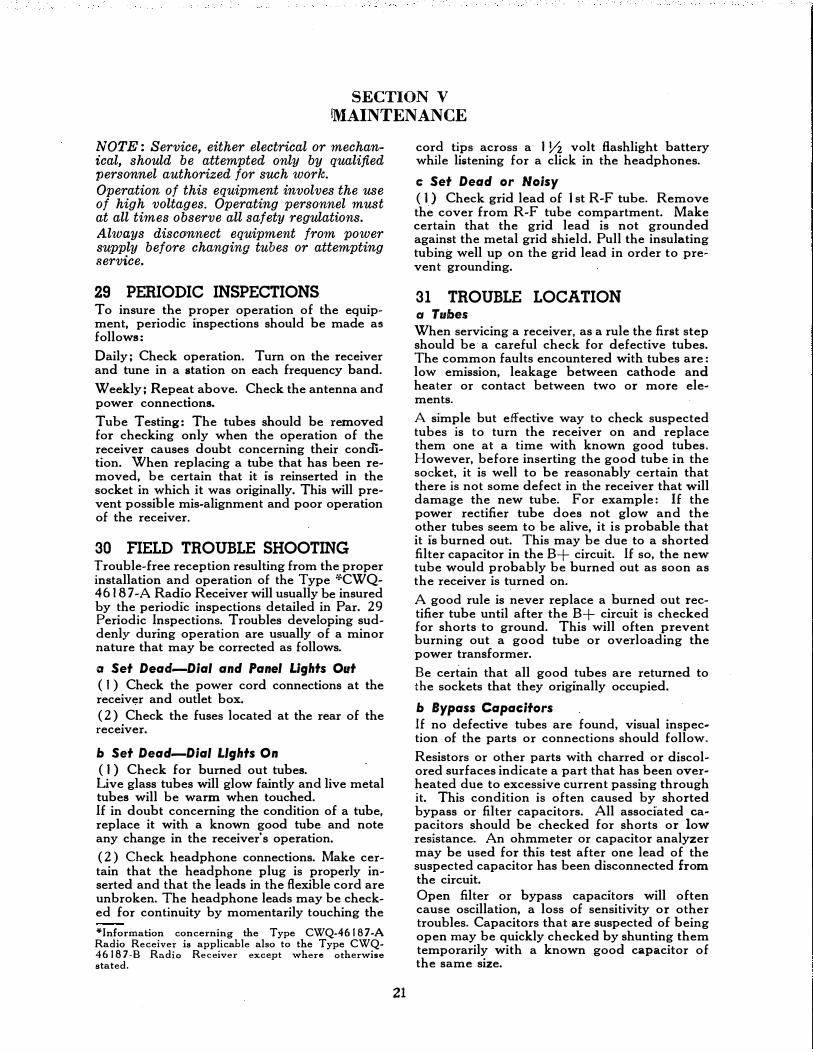
29 PERIODIC INSPECTIONS To insure the proper operation of the equipment, periodic inspections should be made as follows:
Daily; Check operation. Turn on the receiver and tune in a station on each frequency band.
Weekly; Repeat above. Check the antenna and power connections.
Tube Testing: The tubes should be removed for checking only when the operation of the receiver causes doubt concerning their condition. When replacing a tube that has been removed, be certain that it is reinserted in the socket in which it was originally. This will prevent possible mis-alignment and poor operation of the receiver.
30 FIELD TROUBLE SHOOTING Trouble-free reception resulting from the proper installation and operation of the Type '�'CWQ-4618 7 -A Radio Receiver will usually be insured by the periodic inspections detailed in Par. 29 Periodic Inspections. Troubles developing suddenly during operation are usually of a minor nature that may be corrected as follows.
a Set Dead-Dial and Panel Lights Out ( I ) Check the power cord connections at the receiver and outlet box.
( 2) Check the fuses located at the rear of the receiver.
b Set Dead-Dial L.lghts On ( I ) Check for burned out tubes. Live glass tubes will glow faintly and live metal tubes will be warm when touched. If in doubt concerning the condition of a tube, replace it with a known good tube and note any change in the receiver's operation.
( 2) Check headphone connections. Make certain that the headphone plug is properly inserted and that the leads in the flexible cord are unbroken. The headphone leads may be checked for continuity by momentarily touching the
¥Information concerning the Type CWQ-46187-A Radio Receiver is applicable also to the Type CWQ-46 I 87-B Radio Receiver except where otherwise stated.
21
cord tips across a I Yz volt flashlight battery while listening for a click in the headphones.
c: Set Dead or Noisy ( 1 ) Check grid lead of 1st R-F tube. Remove the cover from R-F tube compartment. Make certain that the grid lead is not grounded against the metal grid shield. Pull the insulating tubing well up on the grid lead in order to prevent grounding.
31 TROUBLE LOCATION a Tubes When servicing a receiver, as a rule the first step should be a careful check for defective tubes. The common faults encountered with tubes are: low emission, leakage between cathode and heater or contact between two or more elements.
A simple but effective way to check suspected tubes is to turn the receiver on and replace them one at a time with known good tubes. However, before inserting the good tube in the socket, it is well to be reasonably certain that there is not some defect in the receiver that will damage the new tube. For example: If the power rectifier tube does not glow and the other tubes seem to be alive, it is probable that it is burned out. This may be due to a shorted filter capacitor in the B+ circuit. If so, the new tube would probably be burned out as soon as the receiver is turned on.
A good rule is never replace a burned out rectifier tube until after the B+ circuit is checked for shorts to ground. This will often prevent burning out a good tube or overloading the power transformer.
Be certain that all good tubes are returned to the sockets that they originally occupied.
b Bypass Capacitors If no defective tubes are found, visual inspection of the parts or connections should follow.
Resistors or other parts with charred or discolored surfaces indicate a part that has been overheated due to excessive current passing through it. This condition is often caused by shorted bypass or filter capacitors. All associated capacitors should be checked for shorts or low resistance. An ohmmeter or capacitor analyzer may be used for this test after one lead of the suspected capacitor has been disconnected from the circuit. Open filter or bypass capacitors will often cause oscillation, a loss of sensitivity or other troubles. Capacitors that are suspected of being open may be quickly checked by shunting them temporarily with a known good capacitor of the same size.

INSTRUCTION BOOK FOR NAVY MODELS RA0-3 AND RA0-4
c Tuning Capacitor Noise encountered only while tuning the receiver is generally due to intermittently shorting plates on the tuning capacitor. Should the plates be bent far enough to contact at all times, no noise will be present. Instead, the receiver will be dead on all bands.
Often the plates are shorted only over a portion of their travel, in such a case, the receiver will be dead or noisy, only over a portion of each of the bands.
A visual inspection will usually be sufficient to discover the faulty plates. A more positive check may be made with an ohmmeter after the capacitor has been disconnected from the circuit.
d Resistors Trouble in resistors may usually be divided into three classifications, open, shorted and noisy.
Resistors that are suspected of being shorted or open may be conveniently checked with an ohmmeter. Noisy resistors may in some instances be located by tapping. However, the surest check is to first isolate the stage that the noise seems to originate in and then replace the suspected resistor. A quick way to isolate the troublesome stage is to start with the 1st R-F stage and work towards the output stage removing a tube at a time. The stage that the trouble is in will be the one where removal of the tube stops the noise.
e Coils Trouble in coils will usually be open windings, shorted turns, or a high resistance winding. Coil trouble will usually cause a loss of sensitivity. Such trouble may be found as follows: Open or high resistances, check coil with an ohmmeter. Shorted turns, a measurement of inductance will usually be necessary to discover this fault.
f Switches Switch trouble will usually be found to be dirty or weak contacts. The result of this will be noise, weak reception or possibly a dead receiver. As a rule, a slight pressure or tapping of the switch contacts will be all that will be required to determine which ones are at fault.
g Tube Socket Contacts Weak or dirty tube socket contacts may cause noisy or weak reception or sometimes even a dead receiver. Pressure on the contacts will often locate the defective part. Ohmmeter readings between contact and tube prong may in some instances be of value.
22
h Power Transformer Trouble in power transformers are usually an open winding or shorted turns. Open primary or high voltage secondary windings may be checked with an ohmmeter. It will be necessary to remove the tubes from the sockets to check the low voltage secondary windings.
Should one-half of the high voltage secondary be open, a lower B+ voltage will result and the hum level in the receiver will increase. Shorted turns will also cause low voltage output. This will also be accompanied by excessive heat.
i Output Transformer Usual troubles are open windings, shorted turns or increased resistance of the windings. These troubles may be checked by means of an ohmmeter.
j General Unsoldered terminals, loose wires or grounds caused by hidden solder may be found visually and quickly corrected.
Should such an inspection disclose no faults, the next step should be to tap the various parts, pull the wires at the connections, jar the chassis, etc. This procedure will often result in crackles, squeals, fading or distortion that will show in which circuit or part the trouble lies. If nothing is found by the procedure indicated in the preceding paragraphs, voltage and current measurements followed by resistance and continuity measurements should be made as described in the paragraphs that follow.
32 STAGE GAIN MEASUREMENTS
The approximate gain of each stage is shown in Table A, Stage Gain Measurements. To make measurements of this type, it will be necessary to have a signal generator and output meter. The signal generator must be accurately calibrated and must have an attenuator network capable of providing a signal of one microvolt.
33 VOLTAGE MEASUREMENTS
a General Table B Socket Voltages, shows voltage measurements made from the chassis ground to the more important tube socket terminals. These measurements were made with a 1 000 ohm per volt meter and are readings that will be obtained when using a similar meter on receivers in good condition.
& Procedure ( 1 ) Remove the bottom plate from the cabinet. Supply power to the radio receiver and turn the radio receiver on. Place the controls in

SECTION V -MAINTENANCE
SIGNAL GENERATOR
c:J
\� CONNECT SIGNAL GENERATOR THRU .IMF. CAPACITOR TO GRID Of 6J7 MIXER TUBE.
CONNECT OUTPUT METER TO SPEAKER TERMINAL AT REAR Of RECEIVER
Fig. 22. Connections for I-F Alignment
the positions indicated in Table B, Socket Voltages.
{2) Use the voltmeter ranges indicated in the table and make the desired readings between the terminals shown on the voltage table and ground.
34 RESISTANCE AND CONTINUITY MEASUREMENTS
a General
In Table C, Coil Resistances, are shown the resistance readings of the coils and transformers. These measurements are to b!'! made with test prods at the coil terminals or other points shown in the table. Whenever possible, use an ohmmeter range that will allow the readings to be made on the 0 to 50 portion of the ohmmeter scale.
b Procedure ( I ) Remove the bottom plate from the cabinet and disconnect the power cord from the power supply.
{2) Use the proper ohmmeter scale and adjust the meter to zero ohms. Proceed to make the desired readings.
35 ALIGNMENT
a General Correct alignment is extremely important for the proper operation of the -"'CWQ-4618 7 -A Radio Receiver; however, re-alignment should
�Information concerning the Type CWQ-4 6 18 7 -A
Radio Receiver is applicable also to the Type CWQ-46187-B Radio Receiver except where otherwise stated.
23
not be attempted unless it is certain that the receiver is mis-aligned and then, only after all other possible causes of faulty operation have been fully investigated.
The correct step-by-step alignment procedure is given here and should be followed whenever aligning the receiver. Fig. 25, Trimmer Positions, shows the position of each Trimmer Capacitor.
b Equipment and eonnedions for Alignment
A standard 600 ohm output meter and a signal generator capable of producing both modulated and unmodulated signals between 455 kc and 28 megacycles is necessary for the alignment of the Type �CWQ-46187-A Radio Receiver. This test equipment is to be connected to the �CWQ-46187-A Radio Receiver as shown in the illustrations, and as instructed in the paragraphs that follow:
Unless otherwise directed, the positions of the controls while aligning the receiver are to be as follows:
Controls Position
Power B+ ON S-Meter Switch OFF Limiter Control Zero Tone Control N Control Switch MVC C-W Oscillator Zero A-F Gain Maximum R-F Gain Maximum Phasing Zero Selectivity OFF Band Selector To Desired Band Tuning Knob Adjust for Test Signal

INSTRUCTION BOOK FOR NAVY MODELS RA0-3 AND RA0-4
CONNECT TO ANTENNA INPUT JACK
� 0
SIGNAL GENERATOR
Fig. 23. Connections for R-F Alignment
c: Alignment Proc:ed11re
(I) C-W OSCILLATOR ADJUSTMENT Connect the output meter to the output terminals at the rear of the receiver and connect a signal generator through a . 1 mf. capacitor to the grid of the 6J 7 Mixer tube. Adjust the signal generator for a modulated output at approximately 455 kc. Begin with the 3rd 1-F Transformer and work towards the Mixer tube. Adjust each 1-F tri!llmer for a maximum output as indicated on the output meter.
Turn the signal generator modulation off. Turn the Control switch to the CWO position and with the C-W Osc. control set at zero, adjust the trimmer condenser, C-132, for zero beat.
(2) 1-F ADJUSTMENT Leave the controls in the position as last used for the C-W Oscillator adjustment. Turn the Selectivity control to the No. 5 position. Adjust the signal generator until a point of peak response, as indicated on the output meter, is found. This point will be the exact frequency of the crystal filter and the I-F trimmers are to be realigned at this frequency as follows:
Turn the signal generator modulation ON.
Turn the Selectivity control to OFF and the Control switch to the MVC position. Begin with the 3rd I-F Secondary trimmer, C-1 3 1 , and work towards the Mixer tube, adjusting each trimmer for maximum output in the following sequence, C-131, C-130, C-129, C-128 and C-133. C-133 is adjusted from the underside of the chassis.
(3) CRYSTAL FILTER ADJUSTMENT Turn the Selectivity switch to the No. I position. Leave the other controls as they were for the 1-F alignment. De-tune the signal generator to 5 kc below the frequency at which the 1-F trimmers were aligned. Adjust the trimmer condenser, C-134, for maximum output.
24
Turn the Selectivity control to the OFF position and re-tune the signal generator to the Crystal frequency. Adjust the trimmer condenser, C-125, for maximum output.
Adjust the Phasing control until the capacitor is at its mid position. This may be determined by observing the position of the capacitor plates thru the hole in the top of the Crystal Filter and I st 1-F assembly provided for the adjustment of C-126. De-tune the signal generator 1 0 kc from the alignment frequency and turn the modulation off. Turn the Control switch to the CWO position and the Selectivity switch to the No. 5 position. Adjust the Trimmer Capacitor, C-1 26, for minimum output.
Re-tune the signal generator to the alignment frequency and adjust the C-W Oscillator control until a zero beat condition is obtained. Loosen the set screw that holds the C-W Oscillator knob and adjust the knob until the pointer indicates zero.
Adjust the Phasing control until the tuning plates of the capacitor are at their mid position. Loosen the set screw that holds the Phasing control knob and adjust the knob until the pointer indicates zero.
The alignment at this point may be considered satisfactory if the input required at each stage to produce a 6-milliwatt output does not exceed the following values:
2nd 1-F Grid I st I-F Grid Mixer Grid
15,000 Microvolts 250 Microvolts
2 5 Microvolts
These measurements are to be made with the signal generator modulation turned on.
(4) S-METER ADJUSTMENT
The S-Meter adjustment is to be made with the receiver turned on, the R-F Gain control set at maximum, no signal applied to the receiver

SECTION ¥-MAINTENANCE
TO RECEIVER'S ANTENNA TERMINAL
Fig. 24. Schematic Diagram, Standard RMA Dummy Antenna
and the S-Meter switch turned to ON. Adjust the S-Meter control, R-155, until the S-Meter reads zero.
(5) R-F AND OSCILLATOR STAGE ADJUSTMENTS
The table that follows gives the alignment frequency, trimmer adjustment and proper sensitivity for each of the five frequency bands.
The signal generator is to be connected through a standard RMA dummy antenna to the receiver's antenna terminal. A modulated signal is to be used. The receiver controls are to be positioned as originally specified for the alignment procedure. For the A, B, C and D bands, adjust the trimmers indicated in the table as follows:
Adjust the oscillator trimmer for maximum output. Adjust the Mixer, 2nd R-F and 1st R-F stages, in the order listed, for maximum output.
Adjustments for the E Band are as given for the other bands except that there is an additional oscillator stage adjustment at 600 kc.
TOP VIEW Cf CHASSIS
I R-1�� -�-s METER I ADJUSTMENT
After this adjustment has been made, repeat the 1.2 Me osc. adjustment. Readjust these two trimmers several times until the 600 kc adjustment does not effect the setting of the 1.2 Me osc. trimmer. This will insure correct tracking and dial calibration.
The alignment of the R-F and Oscillator stages may be considered satisfactory if the input necessary to produce a 6-milliwatt output does not exceed the value shown in the right hand column ef the table. Sensi'tivity measurements
1ST R-F 2ND R-F MIXER OS C.
r--,,.\"'--11. ""T" . '"T"' ;T'"' 11� I C-104 G !lr-l C-117 c-118-- c-119 I 0 0 I' I ·I 0 0 0 0 0 0 i A I A2 A3 A4 1 .11/ C-116 It j C-108 C-112 C-120 . 00 11 00 00 00 i B I 82 83 94 !I/ o cos I 1 o c-og o co o cT
C I C2 C3 C 4 i l C-106 C-110 C-114 C-127 11100
I oo oo oo I' D I I D 2 D 3 D 4
i C-107 I
C-1\1 C -115 LF.ADJ. C-122
II 00 I 00 00 00 I
El G II & E2 E3 [4 �
'I I il II I
@.c-133 1ST 1-f
PRI.
lj I' �I u .... a:
.... 0 ,_ z 0 "" "-
L llJUl BOTTOU VIEW OF CHASSIS ] Gbl ""''&'
r·-�-;:� C-131 1-r·, �'ii.fl C-130 ::.rc.-l, �JI PRI.
� .. C-'29� o'"; C-128 Z-12::1
�-->:t:') 3RD 1-�� TRANS.ORMER
s;:c, l�
J PRI.
2Ni:> 1-F TRANSVORMER
Z-IZZ
C-134
CRYSTAL FILTER AND 1ST 1-F ASSEMBLY
'%\ �j0c-12s
fRONT Of RECEIVER
' C-132 C-W OS .ADJ.
' r '�I �" I � 0 t10·W 0"·'"'" '' �' Z-124 ----
Fig. 25. Trimmer Positions
25

INSTRUCTiON BOOK FOR NAVY MODELS RA0-3 AND RA0-4
are to be made with a 1 0 to 1 noise ratio as Freq. of Signal Sensitivity Generator and
follows: Band Receiver Adjustment (Microvolts)
A 28 Me I st R-F C-104 14 Set the receiver to the signal generator fre- 2nd R-F C-1 I 7 quency and turn the signal generator modula- Mixer C-118
tion off. Adjust the signal generator output Osc. C-119
level to the approximate sensitivity expected. B 13.5 Me 1st R-F C-116 8 2nd R-F C-1 08
Adjust the R-F Gain control on the receiver Mixer C-112
until 600 microwatts of noise is indicated on Osc. C-120
the output meter. Turn the signal generator c �.0 Me 1st R-F C-105 16
modulation on and adjust the signal generator 2nd R-F C-1 09 Mixer C-113
level control to a position that will produce a Osc. C-121 6-milliwatt output as read on the receiver's out- D 2.6 Me I st R-F C-106 7 put meter. The strength of the signal supplied 2nd R-F C-11 0 by the signal generator indicates the sensitivity Mixer C-114
of the receiver. Osc. C-127
E 1.2 Me I st R-F C-107 3
(6) R-F AND OSCILLATOR STAGE ALIGNMENT 2nd R-F C-111 Mixer C-115
All adjustments are to be made for maximum Osc. H-F C-122 reading of the output meter. 600 kc Osc. L-F {Core)
26

TABLE A-STAGE GAIN MEASUREMENTS
A-F GAIN
Audio Oscillator-Frequency 600 Cycles
CONTROL POSITIONS
Power Control ......................... ON Tone . . . . . . . . . . . . . . . . . . . . . . . . . . . . . . . . . . . . . . N
R-F Gain ................................ 0 C-W Osc .......................... any position
A-F Gain .............................. 10 Selectivity ......................... any position
Control Switch ........................ MVC Phasing ........................... any position
Limiter ............................... OFF Band Selector ...................... any position
Tuning Knob ....................... any position
Audio Oscillator Connection at Receiver
Across R-136, 500,000 Ohm Resistor at Output Tube Grid
Across R-118, 50,000 Ohm Resistor at Limiter Grid
R-F GAIN
Volts Input Mil!iwatt Output
.7 �6
.04 6
Signal Generator Modulation-400 Cycles, 30%
CONTROL POSITIONS
Power Control .............................. ON
R-F Gain ....... Adjust For 600 microwatt noise level See column" Approximate R-F Gain control setting for noise level."
A-F Gain .................................. 10
Control Switch ............................ MVC
limiter ................................... OFF
Tone ................................ N
Phasing .............................. 0 C-W Osc . . . . . . . . . . . . . . . . . . . . .... . . . . . o
Selectivity ......................... OFF Band Selector .................... Band C Tuning Knob .................. See Below
(Grid Caps may Be Left on Tubes)
Connection Between Signal I Signal Generator Generator Signal
and Connection to Generator Receiver Receiver Frequency
.1 mf Detector Grid 456KC
.1 mf 2nd 1-F Grid 456KC
.1 mf 1st 1-F Grid 456KC
.1 mf Mixer Grid 456KC .1 mf 2nd R-F Grid 4MC .1 mf *1st R-F Grid 4MC
Standard RMA 1 Antenna 4MC Terminal Dummy Antenna
. -----------
*Remove cover from 1st R-F tube box and grid shield
Receiver Dial
Setting
. . ' ' . . . . . ' . .
. . . . . . . . . .
. . . . . . . . . . . .
4MC 4MC 4MC
27
Approximate R-F Gain
Control Setting for Correct
Noise Level --
Maximum Maximum Maximum Maximum
9.1 8.2 8 I
Noise Level
Microwatts
. . .. . . . . . . . '
400 600 600 600
Microvolt Input for Six
Milliwatt Output
720,000 10,300
150 14 14 12
3.6

5Z3 RECTIFIER 2
@15 • 215
F F
®®
9 p
187 -32 -13
POWER TRANSFORMER T-101
3 2 I BL-�01 8
8 8 8 6 5 4 8 8 8 Bt FILTER CHOKE 9 8 7
8 8 8 8L-io28
6K6GtiG AUDIO OU�PUT
'VOLTAGES R
A A G) UNDER COND����CT SOCKETS '\{}/ '\{}/ IN TABLE 8- SOC
S SPECIFIED KET VOLTAGES
BOTTOM VIEW OF CHASSIS
6K7 2ND R.F.AMP.
188
68
6K7 2ND I.F.AMP.
6F8G 1ST AUDIO
AMP.&A.V.C.
2e7H G �K .I
-39 K p H 0
188
6J7 MIXER
187
73
6C8G 2ND DET.
& LIMITER
192eH G .-...: K .S
.OS K � p H 0
6J5 H.F.OSC.
e
36
108 i4 G
0
6K7
6J7 c.w.osc.
16\JK 0
fiH c p 16 32
FRONT OF CHASSIS
Fig. 26. Bottom Socket View of Type CWQ-46187-A Radio Receiver
28

5Z3 T-101 POWER
RECTIFIER 2�15 • 215 0
G G 0
I TRANSFORMER I BL-�01 8
F F
®®
&7. p
87 -lZ -1 3
6K6Gl/r. AUDIO OU�PUT
'A<;II
0
<,} 0
0 u EJ LJ 0 u
VOLTAGES READ AT SOCKETS UNDER CONDITIONS SPECIFIED
JUMPER TERMINAL BOARD CONNECTED
FOR 115V. Bt FILTER CHOKE OPERATION
8 L-ioz 8
<DG>G> IN TABLE A-VOLTAGE READINGS
BOTTOM VIEW OF CHASSIS
6K7 2ND R.F. AMP.
6188
68
15 15
6K7 2ND I.F.AMP.
17.5
6F8G 1ST AUDIO
AMP. & A.V.C.
68
2e
7H G ..,K .I
-39 K p H
0
0 N
6J7 MIXER
e
187 7
3
c 5 5
73
6J5 H.F.OSC.
0
36
108
G 0
17.5 6K 7 17.&u H 1ST I.F .AMP.
68 .. K 17.5 p H
188 H
6C8G 2ND DET
& LIMITE.R
19.G
P H
.05 K �K '5
p H 0
6J7 c.w.osc.
16GK o
sufiH·
c p
16 32
FRONT OF CHASSIS
~ [D IT)
[0 IT)
[[) [D [[)
JUMPER TERMINAL BOARD CONNECTED FOR 230 V. OPERATION.
0
Fig. 27. Bottom Socket View of Type CWQ-46187-B Radio Receiver
29

TABLE B-SOCKET VOLTAGES
All Voltages are approximate and are read between the socket terminals and chassis ground with a I 000 ohm-per-vol(meter under the following conditions:
Line Voltage 115 Volts
Plate and Screen Voltages Read on 250 Volt Scale
Cathode Voltages Read on Highest Scale That Permits Value To Be Read Easily
Tube Plate Volts & &
Function Term. No.
Power Control - B+ ON
R-F Gain - 0
Control Switch - MVC
Limiter Control - 0
Screen Volts Cathode Vo;ts & &
Term, No. Term. No.
6K7 Tube prongs are not accessible for voltage measurements 1st R-F
6K7 188 68 15 2nd R-F No, 3 No, 4 No.8
6J7 187 73 5 Mixer No.3 No.4 No.8
6J5 36 0 H-F Osc. No.3 No.8
6K7 188 68 1 7.5 1 st I-F No. 3 No. 4 No.8
6K7 185 88 17.5 2nd 1-F No.3 No.4 No.8
6 C8G 0 .05 2nd Det. & No.3 No. 4
Lim. 192 .5 No. 6 No.8
6J7 * 32 * 16 0 C-W Osc. No. 3 No.4 No.8
6 F8G 0 -39 1st A-F & No. 3 No. 4
AVC 27 .I No. 6 No.8
6K6GT/G 175 185 -32 Audio Outpuut No.3 No. 4 No.8
5Z3 215 Rectifier Nos. I & 4
* Voltages read with Control switch tuned to the CWO position.
OCTAL SOCKET BOTTOM TERMINAL NUMBERING
30

TABLE C-COIL RESISTANCES
Resistances shown are approximate resistance values of coils and transformers. Colors shown for 1-F transformer terminals are the colors of the wires soldered to the transformer terminal..
Symbol Terminals Resistance is DC Resistance
Desig. Name of Part Winding Measured Across in Ohms
L-101 B+ Filter Choke 300
L-102 B+ Filter Choke 300
L-103 1-F Coil 9.5
*T-1 01 Power Transformer RA0-3 Primary 1-4 2.4 H.V. Secondary 3-9 179 6.3 V. Secondary 7 - 8 .051 5. V. Secondary 2-5 .091
T-102 Output Transformer Primary Red-Blue Leads 350
Secondary Green-Yellow Leads 32
T-103 1st 1-F Transformer Primary 7.12 Secondary 2.57
*T-104 Power Transformer RA0-4 Primary No. 1 1 - 10 4.35 Primary No. 2 4 - 11 5.53
Z-101 1st R-F Transformer Primary .148 Secondary .029
Z-102 1st R-F Transformer Primary .18 Secondary .087
Z-103 1st R-F Transformer Primary .372 Secondary .46
Z-104 1st R-F Transformer Primary .486 Secondary 1.335
Z-105 1st R-F Transformer Primary .811 Secondary .391
Z-106 2nd R-F Transformer Primary .812 Secondary .043
Z-107 2nd R-F Transformer Primary 3.66 Secondary .09
Z-108 2nd R-F Transformer Primary 13.95 Secondary .46
Z-109 2nd R-F Transforme; Primary 27.18 Secondary 1.37
Z-110 2nd R-F Transformer Primary .83 Secondar.y 4.05
--------
*The information given on the secondary windings of the Powec Transformer T-101 used in the RA0-3, also applies to the secondaries of the Transformer T-104 used in the RA0-4.
31

TABLE C-COIL RESISTANCES-Continued
Symbol .Terminals Resistance is DC Resistance Desig. Name of Part Winding Measured Across in Ohms
--- --
Z-111 Mixer Transformer Primary .810 Secondary .043
Z-112 Mixer Transformer Primary 3.655 Secondary .09
Z-113 Mixer Transformer Primary 13.95 Secondary .46
Z-114 Mixer Transformer Primary 27.0 Secondary 1.37
Z-115 Mixer Transformer Primary .764 Secondary 4.01
Z-116 Osc. Transformer Grid .03 Plate .068
Z-117 Osc. Transformer Grid .07 Plate .082
Z-118 Osc. Transformer Grid .133 Plate 388
Z-119 Osc. Transformer Grid .0913 Plate .156
Z-120 Osc. Transformer Grid .784 '
Plate 2.27
Z-121 Crystal Filter and 1-F Assembly See T-103 and L-103
Z-122 2nd 1-F Transformer Primary Red Tracer-Blue Tracer 7.5 Secondary Black Tracer-Grid Clip 7.5
Z-123 3rd 1-F Transformer Primary Red Tracer-Blue Tracer 7.5 Secondary Black Tracer-Green Tracer 7.5
Z-124 C-W Oscillator Coil Black Tracer-Green Tracer 9.7
(Terminals Inside Can)
-
32

TABLED-CATHODE CURRENTS
Measurements made under following conditions:
No signal received
Line Voltage . . . . ............. . . . . . . . . 11 5 Volts
Power Control .......................... B+ ON
R-F Gain . . . . . . . . . . . . . . . . . . . . . . . . . . . . . . . . . . . . 5
A-F Gain . . . . • • . . . . . . . . . . . . . . . . . . . . . . . . . . . • 10
Control Switch .. MVC except where otherwise noted
Tube
6K7
6K7
6J7
6J5
6K7
6K7
6C8G
----------
Cathode Function Current
I 1st R-F. . . . . . . . . . . . 1 4.5 Mo
2nd R-F................ .7 Ma
Mixer .................
Oscillator ..............
1st 1-F .................
2nd 1-F ................
2nd Det. and Limiter 2nd Det ................
Limiter .............. - �-----
14. Ma
2. Ma
.5 Ma
1. Ma
.1 Ma
.4 Ma ---------- �-
*Control Switch Turned to CWO Position.
33
Limiter........................ . .... 0
C-W Osc . . . . ... . ...... . ... . . . ... . . . . . 0
Selectivity ......................... OFF
Band Selector ................ any position
Tuning Knob ................. any position
Tone . . . . . . . . . . . .. . . . . . . . . . .. . . . . . . . . N
Cathode Tube Function Current
*6J7 C-W Osc .............. .4 Ma
6F8G AVC and 1st A-F I
AVC ............. .OMa
Audio ............ .5 Ma
6K6GT Output ............... 30. Ma
5Z3 Rectifier ............... 54. Ma
---- I

TABLE E-COLOR CODING
COLOR CODE FOR CAPACITORS
Color Numerals Multiplier Volts Tolerance
Black 0 Brown I Red 2 Orange 3 Yellow 4 Green 5 Blue 6 Violet 7
Gray 8 White 9 Gold Silver No Color
1ST NUIABER
WORKING VOLTAGE
I 10
100 1,000
10,000 100,000
1,000,000 10,000,000
I 00,000,000 1,000,000,000
0.1 0.01
2ND NUIABER
I
TOLERANCE
100 200 300 400 500 600 700 800 900
1000 2000
500
1% 2% 3% 4% 5% 6% 1'% 8% 9"/o 5%
10% 20%
----.--3RD NUIAB[R
DWIAAL IAULTIPLIER
AMERICAN WAR STANDARDS COLOR CODE FOR FIXED MICA CAPACITORS
VALUES READ IN MMF 1st, 2nd, · Decimal Toler- Character-
Color 3rd No. • Multiplier a nee lstic Black 0 I A Brown I 10 B Red 2 100 2% c
Orange 3 1,000 D
Yellow 4 E Green 5 F
Blue 6 G Violet 7 Gray 8 White 9 Gold 0.1 5% Silver 0.01 10'% Black 20%
34
COLOR CODE FOR RESISTORS
Color
Black Brown Red Orange Yellow Green Blue Violet Gray White
1st Number
I 2 3 4 5 6 7
8 9
2nd Number
0 I 2 3 4 5 6 7 8 9
Tolerance Color Code Values
Multiplier
I 10
100 1,000
10,000 100,000
1,000,000
Gold 5"/o Silver 10% No Color 20"/o
/.Vf//r///4j-*"£N� TOLERANCE
END, 2ND NUMBER
I ST NUMBER
2ND NUMBER
1ST NUIAB(R
DOT, MULTIPLIER
2ND NUMBER
u
� I
3RO '""""
CHARACTEAISTIC � .ttorc:."utJPLIEA
TOLERANCE

TABLE F-LIST OF MAJOR UNITS
QUANTITY ASSEMBLY NAVY TYPE NAME OF SYMBOL DRAWING
(MODEL RA0-3 MODEL RA0-4 DESIGNATION MAJOR UNIT GROUP NUMBER
1 • • • • • • 0 0 • • • • • • • • • • CW0-46187-A Radio Receiver 101 and up 25A618
. . . . . . . . . . . . . . . . . . 1 CWQ-46187-B Radio Receiver 101 and up 25A691
1 • 0 • • � • • • • • • • • • 0 • • • CW0-1 0125-A Mounting Base 301 and up 25A634
. . . . . . . . . . . . . . . . . . 1 CW0-1 0125-A Mounting Base 301 and up 25A635
. . . . . . . . . . . . . . . . . . 2 49016 Headphones . . . . . . . . . . . . . . . . . . . . . . . . . . . . . . . . . . . . . . . .
. . . . . . . . . . . . . . . . . . 2 49034 Plug . . . . . . . . . . . . . . . . . . . . . . . . . . . . . . . . . . . . . . . .
35
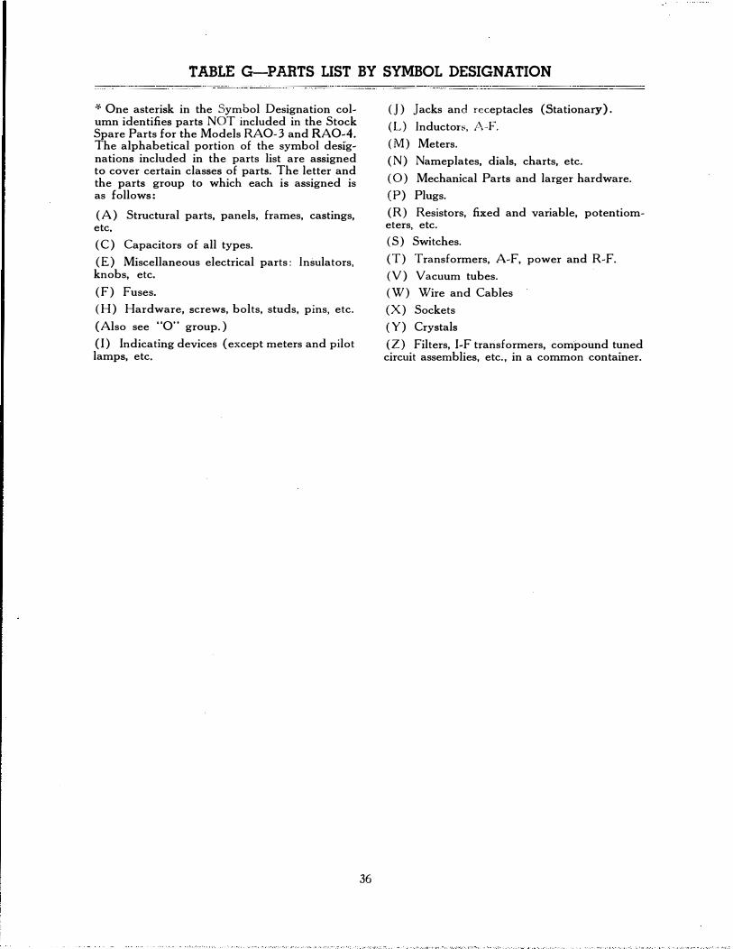
TABLE G-PARTS LIST BY SYMBOL DESIGNATION
:f. One asterisk in the Symbol Designation column identifies parts NOT included in the Stock Spare Parts for the Models RA0-3 and RA0-4. The alphabetical portion of the symbol designations included in the parts list are assigned to cover certain classes of parts. The letter and the parts group to which each is assigned is as follows:
(A) Structural parts, panels, frames, castings, etc.
(C) Capacitors of all types.
(E) Miscellaneous electrical parts: Insulators, knobs, etc.
(F) Fuses.
(H) Hardware, screws, bolts, studs, pins, etc.
(Also see "0" group.)
(I) Indicating devices (except meters and pilot lamps, etc.
36
(]) Jacks and receptacles (Stationary).
(L) Inductor::<, /\-F.
(M) Meters.
(N) Nameplates, dials, charts, etc.
( 0) Mechanical Parts and larger hardware.
(P) Plugs.
(R) Resistors, fixed and variable, potentiometers, etc.
(S) Switches.
(T) Transformers, A-F, power and R-F.
( V) Vacuum tubes.
(W) Wire and Cables
(X) Sockets
( Y) Crystals
(Z) Filters, I-F transformers, compound tuned circuit assemblies, etc., in a common container.

w 'l
TABLE G-PARTS LIST BY SYMBOL DESIGNATION
FOR NAVY MODELS RA0-3 AND RA0-4 RADIO RECEIVING EQUIPMENT *One asterisk in the Symbol Designation column identiAes parts NOT included in the Stock Spare Parts. (The Stock Spare Parts are those supplied as spare p�rts but not shipped to the same destination as the receiving equipment.)
Navy Special Contractor's Symbol Navy Type Specification Mfr. Tolerance Drawing Desig. FUNCTION DESCRIPTION Number or Drawing Mfr. Desig. Rating or and
Number Modification Part No.
*A-101 Dial Window DIAL WINDOW, Cellulose Acetate, Water Clear. 7.000" x I 7 17X79 4.000" X .093" Thick
*A-102 RectiAer Tube Clamping TUBE CLAMP, .015" High Carbon Tempered Steel. Over- 11 8527 30X424 Ring all 2.156" x 1.562" x .437" High. Cadmium Plated and Clear
Lacquer Finish
*A-103 Tuning Scale Mounting TUNING SCALE BRACKET, .031" C.R. 74 Hard Steel. Double Angle Type. Overall 3.062" x 1.718". Cadmium
41 25X1273
Plated and Clear Lacquer Finish
*A-104 Receiver Bottom Cover BOTTOM PLATE, C.R. Steel. 16.906" x 11.062" x .062" Thick; Cadmium Plated and Clear Lacquer Finish. Part of
47 34X407
A-109
*A-105 Receiver Bottom Rest GLIDER, Stainless Steel, Overall .312" x .750" Dia., .109" 44 20X1013 and A-106 x .275" Dia. Mtg. Stud, .562" R. Base. Part of A-109
*A-107 Same as A-1 05 GLIDER, Sc:me as A-105, Except Part of A-117 and A-108
*A-109 Same as A-104 and BOTTOM PLATE ASSEMBLY, Consists of A-1 04, A-1 05 47 25A679 A-105 and A-106
*A-110 Chassis Mounting CABINET, C.R. Steel, Overall, 17.532" x 11.516" x 1 0.468" 21 34X384 and Protection High. Front and Side Panels. Black Wrinkle Finish
*A-111 Cabinet Top Cover Plate TOP COVER, C.R. Steel, Overall 15.781" x 1 0.1 09" x 47 34X385 .0475" Thick; with 3 Hinges Spotwelded to Rear of Plate. Black Wrinkle Finish
*A-112 front Coil Carriage ROD, SAE 1112 Steel, 16.843" x .437" Dia. *1 0-32 Tap 3 26X428 Guide Hole Centered Each End, .500" Deep. Copper Plated
*A-113 Rear Coil Carriage Guide ROD, Same as A-112
*A-114 Shaft, 0-108, Retainer BUSHING, Brass. Overall Length .468" x .2515" J.D. Hex 31 29X436 Shoulder .093" x .500" across Flats . .437"-27 Ext. Thd. to within .062" of Shoulder. Dull White Nickel Finish
*A-115 Shaft, 0-107, Retainer BUSHING, Brass. Overall Length 1.000" x .2515" I.D. Hex 31 29X435 Shoulder .562" x .500" across Flats . . 457"-27 Ext. Thd. to within .125" of Shoulder. Cutout in Shoulder Dull White Nickel finish
•A-116 Shaft, 0-107, Locking SHAFT RETAINING SPRING, .031" Music Wire. Semi- 38 28X425 Spring Hair Pin Type. Cadmium Plated
*A-117 Rear Channel Bottom Cover BOTTOM PLATE AND GLIDER ASSEMBLY (Prese- 47 25A710 lector). C.R. Steel. 17.095" x 4.125" x .062". Cadmium Plated an� Clear Lacquer finish. Includes A-1 07 and A-1 08

TABLE G-PARTS LIST BY SYMBOL DESIGNATION FOR NAVY MODELS RA0-3 AND RA0-4
Navy Special Contractor's s0m?ot Navy Type Specification Mfr. Tolerance Drawing
es1g. FUNCTION DESCRIPTION Number or Drawing Mfr. Desig. Rating or and Number Modification Part No.
*A-118 Gear Covering at Front GEAR CASE, .025" Brass, 3.562" O.D., 2.875" J.D. Cir- 47 4X790 Panel cular Flange .250", Black Wrinkle Finish
•A-119 Jack, J-102, Mounting JACK MOUNTING BRACKET, .062" C.R. Steel, L Shaped 47 25X1245 One Side, 1.812" x 1.500". Vertical Plate 2.250" x 1.812".
it.,·�'
Jack Mtg. Opening . 765" Dia.; Cadmium Plated
*A-120 Meter, M-101, Mounting MOUNTING BRACKET, Overall Length 5.906", Meter Mtg. Opening 2.125", Two Flanges 1.000" x .593". Cad-mium Plated and Clear Lacquer Finish
47 25X1227
*A-121 Coil Carriage Covering COIL CARRIAGE COVER PLATE, Aluminum, 8.812" x 8.390" x .040". Thirty .500" Dia. Air Vents. Caustic Dip Finish
47 57X109
*A-122 Dial Opening Cover Plate ESCUTCHEON, .032" C.R. Steel. Overall 11. 750" x 6.687". Black Wrinkle Finish
47 4X770
A-301 Cradle Mounting LORD MOUNT, C.R. Steel Frame, 3.000" Square, Cadmium 33 200PH- 8X145 thru A-304 Plated. Floating Rubber Mount with Metal Insert. Mtg. 20
Opening .391" Dia.
*A-305 Receiver Mounting CRADLE ASSEMBLY, Includes Symbol Designations 47 25A634 A-301 thru A-304, A-306, H-301 thru H-304, and Hard-ware
'"A-306 Same as A-305 CRADLE, C.R. Steel. Overall, 17.686" x 16.217", Corners, 47 22X405 1.687" High; With Four Radio Receiver Unit Mtg. Hubs. Black Wrinkle Finish
CAPACITORS
*C-101A 2nd R-F Tuning CAPACITORS, Variable. Range 0.0 mmf. to 224.3 mmf. Effective
40 820-3-31 14A166
*C-101 B Mixer Tuning CAPACITOR, Same as C-101A
*C-101C Osc. Tuning CAPACITOR, Same as C-101A
*C-102 1st R-F Tuning CAPACITOR, Variable. Range 0.0 mmf. to 224.3 mmf. Effective
40 821-1-31 14A167
•C-1 03 Phasing Control CAPACITOR, Trimmer. Range, 2.5 mmf. to 6.3 mmf.; 46 17A211 Ceramic Base. Must Withstand Breakdown Test of 500 Volts R.M.S. 60 Cycle Knob Adjustment
*C-104 1st R-F Trimmer, CAPACITOR, Trimmer. Range, 2.7 mmf. to 14.0 mmf.; 46 17A206 A Band Ceramic Base. Must Withstand Breakdown Test of 500 Volts
R.M.S. 60 Cycle and 200 Hr. Salt Spray Test. Screwdriver Adjustment
*C-105 1st R-F Trimmer, C Band CAPACITOR, Same as C-104
*C-106 1st R-F Trimmer, D Band CAPACITOR, Same as C-104
l

w 1.0
s0m�ol es1g.
*C-107
*C-1 08
*C-109
*C-11 0
*C-111
*C-112
*C-113
*C-114
*C-115
*C-116
*C-117
*C-118
*C-119
*C-120
*C-121
*C-122
*C-123
*C-125
*C-126
*C-127
*C-128
*C-129
*C-130
TABLE G-PARTS LIST BY SYMBOL DESIGNATION FOR NAVY MODELS RA0-3 AND RA0-4
Navy Navy Type Specification Mfr.
FUNCTION DESCRIPTION Number or Drawing Mfr. Desig. Number
1st R-F Trimmer, E Band CAPACITOR, Same as C-104
2nd R-F Trimmer, B Band CAPACITOR, Same as C-104
2nd R-F Trimmer, C Band CAPACITOR, Same as C-104
2nd R-F Trimmer, D Band CAPACITOR, Same as C-104
2nd R-F Trimmer, E Band CAPACITOR, Same as C-104
Mixer Stage Trimmer, B Band CAPACITOR, Same as C-104
Mixer Stage Trimmer, C Band CAPACITOR, Same as C-104
Mixer Stage Trimmer, D Band CAPACITOR, Same as C-104
Mixer Stage Trimmer, E Band CAPACITOR, Same as C-104
1st R-F Trimmer, B Band CAPACITOR, Same as C-104, Except Range to 3.0 mmf. to 25.0 mmf.
46
2nd R-F Trimmer, A Band CAPACITOR, Same as C-116
Mixer Stage Trimmer, A Band CAPACITOR, Same as C-116
Osc Trimmer, A Band CAPACITOR, Same as C-116
Osc Trimmer, B Band CAPACITOR, Sam<e as C-116
Osc Trimmer, C Band CAPACITOR, Same as C-116
Osc Trimmer, E Band CAPACITOR, Same as C-116
C-W Osc Control CAPACITOR, Trimmer. Range, 3.0 mmf. to 12.0 mmf.; 46 Ceramic Base. Rotor and Stator Assemblies, Brass, Silver Plated. Must Withstand Breakdown Test of 500 Volts R.M.S. 60 Cycle and 200 Hr. Salt Spray Test. Knob Adjust-ment
Selectivity Adjustment CAPACITOR, Trimmer. Range, 3.0 mmf. to 35.0 mmf.; 46 Ceramic Base. Test for Breakdown between Capacitor Ele-ments at 350 Volts R.M.S. 60-600 Cycles for 3 Seconds
1st 1-F Secondary Trimmer CAPACITOR, Same as C-125
Osc Trimmer, D Band CAPACITOR, Same as C-104, Except Range to be 5.0 46 mmf. to 35.0 mmf.
2nd 1-F Primary Trimmer CAPACITOR, Trimmer. Range, 4.5 mmf. to 80.0 mmf.; Ceramic Base. Must Withstand Breakdown Test of 500
46
Volts R.M.S. 60 Cycle and 200 Hr. Salt Spray Test
2nd I -F Secondary Trimmer CAPACITOR, Same as C-128
3rd 1-F Primary Trimmer CAPACITOR, Same as C-128
Special Contractor's Tolerance Drawing Rating or and
Modification Part No.
17A205
17A220
17A210
17A207
17A219

TABLE G-PARTS LIST BY SYMBOL DESIGNATION FOR NAVY MODELS RA0-3 AND RA0-4
Navy srcecial Contractor's Symbol Navy Type Specification Mfr. To erance Drawing Desig. FUNCTION DESCRIPTION Number or Drawing Mfr. Desig. Rating or and
- Number Modification Part No.
*C-131 3rd 1-F Secondary Trimmer CAPACITOR, Same as C-128
*C-132 C-W Osc Trimmer CAPACITOR, Same as C-128
•C-133 1st 1-F Primary Trimmer CAPACITOR, Trimmer. Range 6.0 mmf. to 98.0 mmf.1 46 17A218 Ceramic Base. Must Withstand Breakdown Test of 500 Volts R.M.S. 60 Cycle and 200 Hr. Salt Spray Test. Screwdriver Adjustment
*C-134 1st 1-F Output Coil Trimmer CAPACITOR, Same as C-133 809A115
*C-135 Selectivity Switch Series CAPACITOR, Fixed, Ceramic, 5.0 mmf. =20% 481576 8 47X332 811-154
*C-136 Same as C-135 CAPACITOR, Fixed, Ceramic, 10.0 mmf. =10% 481577 8 47X333
*C-137 Same as C-135 CAPACITOR, Same as C-136 813-161
*C-138 1st 1-F Secondary CAPACITOR, Fixed, Ceramic, 50.0 mmf. =10% 8 47X355 and Compensating Capacitor C-139
*C-140 C-W Osc. Plate Coupling CAPACITOR, Bakelite, 1.0 mmf. =20%, 400 VDC 45 Type GA A-7344 47X365 Working
C-145 A VC Diode Coupling CAPACITOR, Fixed, Molded Mica, 50.0 mmf. 500 V DC Working
=10%, 481279 42 K-1450 47X331
C-146 2nd Det. Cathode Bypass CAPACITOR, Fixed, Molded Mica, 250 mmf. 500 V DC Working
=10%, 48690 42 K-1325 47X356
*C-147 2nd Det. Grid Bypass CAPACITOR, Same as C-146
*C-148 1st Audio Plate Bypass CAPACITOR, Same as C-146
C-149 Tone Control CAPACITOR, Fixed, Molded Mica, 700 mmf. =10%, 500 V DC Working
481016 42 C-1370 47X349
C-150 C-W Osc. Grid CAPACITOR, Fixed, Molded Mica, 1000 mmf. =10%, 500 V DC Working
48983 42 C-1210 47X340
C-151 1st R-F A VC Filter CAPACITOR, fixed, Molded Mica, 7000 mmf. V DC Working
=10% 481106 42 C-1270 47X348
*C-152 Hum Neutralizing CAPACITOR, Same as C-146
C-155 Osc. Grid Coupling CAPACITOR, Fixed, Silvered Mica, 100 mmf. 500 V DC Working
=10%, 48843 42 K-131 0 47X357
C-156 Osc. Series, E Band CAPACITOR, Fixed, 500 V DC Working
Silvered Mica, 300 mmf. =5%, 48854 42 K-1330 47X353
C-157 Osc. Series, D Band CAPACITOR, Fixed, Silvered Mica, 800 mmf. =5%, 481428 42 C-1380 47X354 500 V DC Working
I
C-158 Ant. Series, A Band CAPACITOR, Fixed, 500 V DC Working
Silvered Mica, 980 mmf. =5%, 481083 42 C-1398 47X352
*C-159 Osc. Series, A Band CAPACITOR, Same as C-158 -
C-160 . Osc. Series, C Band CAPACITOR, Fixed, Silvered Mica, 1360 mmf. =5%, i 42 C-12136 47X351 I
500 V DC Working I

"""' .....
TABLE G-PARTS LIST BY SYMBOL DESIGNATION FOR NAVY MODELS RA0-3 AND RA0-4
I Navy Symbol
I Navy Type Specification Mfr.
Desig. FUNCTION DESCRIPTION Number or Drawing Mfr. Desig. Number
C-161 Osc. Series, B Band CAPACITOR, Fixed, Silvered Mica, 3100 mmf. ='=5%, I 42 C-1310 300 V DC Working
*C-165 1st R-F Plate Bypass CAPACITOR, Fixed, Tubular, Paper, .01 mf. ='=10%, 600 481567 19 3412BB V DC Working
*C-166 2nd R-F A VC Bypass CAPACITOR, Same as C-165
*C-167 2nd R-F Plate Bypass CAPACITOR, Same as C-165
*C-168 Osc. Mixer Coupling CAPACITOR, Same as C-165
*C-169 1st 1-F A VC Bypass CAPACITOR, Same as C-165
*C-170 AVC Bypass CAPACITOR, Same as C-165
*C-171 2nd 1-F A VC Bypass CAPACITOR, Same as C-165
*C-112 Grid Coupling, CAPACITOR, Same as C-165 1st Audio Stage
*C-173 Tone Control Capacitor CAPACITOR, Same as C-165 481568 19 3483A
*C-174 2nd Det. Plate Bypass CAPACITOR, Fixed, Tubular, Paper, .05 mf. ='=10%, 600 V DC Working
*C-175 B+ Bypass CAPACITOR, Same as C-174
*C-176 1st R-F Cathode Bypass CAPACITOR, Fixed, Tubular, Paper, .01 mf. ='=10%, 400 V DC Working
481569 19 A7830
*C-177 1st R-F Filament Filter CAPACITOR, Same as C-176
*C-178 1st R-F Screen Resistor Bypass CAPACITOR, Same as C-176
*C-179 2nd R-F Cathode Bypass CAPACITOR, Same as C-176
*C-180 1st R-F Screen Bypass CAPACITOR, Same as C-176
*C-181 1st 1-F Cathode Bypass CAPACITOR, Same as C-176
*C-182 2nd 1-F Cathode Bypass CAPACITOR, Same as C-176
*C-183 2nd 1-F Screen Bypass CAPACITOR, Same as C-176
*C-184 Output Grid Coupling CAPACITOR, Same as C-176
*C-185 A VC Plate Bypass CAPACITOR, Same as C-176
*C-186 A VC Cathode Bypass CAPACITOR, Same as C-176
*C-187 C-W Osc. Screen Bypass CAPACITOR, Same as C-176
*C-188 Audio Output Cathode Bypass
CAPACITOR, Same as C-176
_*C-1_1!�- Mixer Ca�hode B_y_p�ss CAPACITOR, Same as C-176, Exce�t with Mounting Strap I 19 A7654 I
Special Contractor's Tolerance Drawing Rating or and
Modification Part No.
47X350
46X360
46X363
46X371
46X372

TABLE G-PARTS LIST BY SYMBOL DESIGNATION FOR NAVY MODELS RA0-3 AND RA0-4
Navy Special Contractor's Symbol Navy Type Specification Mfr. Tolerance Drawing Desig. FUNCTION DESCRIPTION Number or Drawing Mfr. Desig. Rating or and
Number Modification Part No.
*C-190 Mixer Plate Bypass CAPACITOR, Fixed, Tubular, 600 V DC Working
Paper, 0.1 mf. ±10%, 481570 19 A3486 46X361
*C-191 1st 1-F Plate Bypass CAPACITOR, Same as C-190 '
*C-192 2nd 1-F Plate Bypass CAPACITOR, Same as C-190
*C-193 1 sl Audio Plate Bypass CAPACITOR, Same as C-190
*C-194 2nd Det. Cathode Coupling CAPACITOR, Fixed, Tubular,· Paper, 200 V DC Working
1.0 mf. ±10%, 481572 19 7652 46X362
*C-195 1st Audio Cathode Bypass CAPACITOR, Same as C-194
*C-196 Negative Bias Supply Filter CAPACITOR, Same as C-194 and C-197
*C-200 Power Supply Filter CAPACITOR, Fixed, Oil Filled, Paper. 4.0 mf. ±10%, 481080 56 48X249 thruC-202 600 V DC Working
MISCELLANEOUS ELECTRICAL PARTS
*E-101 Meter Lamp Socket Spacer GROMMET, Rubber, .250" Groove: .062" x .500" O.D.
X .625" 0.D., .375" J.D. 6 230 6X40
*E-102 1st R-F Tube Leads GROMMET, Same as E-101 Insulator
*E-103 Rear of Tuning Capacitor GROMMET, Rubber, .312" x .625" O.D., .265" I.D. 6 1240 6X41 Mtg. Cushion Groove: .062" x .468" O.D.
*E-104thru Coil Leads from Channel GROMMET, Rubber, .250" x .437" O.D., . 187" I.D . 6 2286 6X47 E-109 Insulator Groove: .062" x .312" O.D.
*E-110 Tuning Meter Adj. Control, WASHER, Hard Black Fibre, .032" x .625" O.D., .380" I.D. 30 2X395 R-155, Mounting Insulator
*E-111 Same as E-110 SHOULDER WASHER, Hard Black Fibre. Washer: .042" x 30 2X394 .495" O.D., .380' I.D.; Shoulder: .051" x .875" O.D.
*E-112 Phone Jack, J-1 01, SHOULDER WASHER, Hard Black Fibre. Washer: .031" x 30 2X392 and E-113 Mounting Insulator .437" O.D., .380" I.D.; Shoulder: .031" x .625" O.D.
*E-114 Coil Contacts Mounting CONTACT PANEL, Bakelite. Overall, 2.500" x 1.250" x 9 1X224 thru E-116 .250" Thick. Five Contact Slots .390" x .187" Tapering to
.050"
*E-117 Speaker Connections TERMINAL PANEL. Bakelite, Two Screw Terminals with 11 1720 Marked SPKR 4A274 Lugs. Panel Lettered, SPKR
*E-118 Osc. Coil Section COIL CONTACT INSULATOR, Sheet Fibre. Overall, 28 16X82 Contact Insulator .875" x .562" x .007" Thick

� w
TABLE G-PARTS LIST BY SYMBOL DESIGNATION FOR NAVY MODELS RA0-3 AND RA0-4
Navy Symbol Navy Type Specification Mfr. Desig. FUNCTION DESCRIPTION Number or Drawing Mfr. Desig.
Number
*E-119 thru 1 Vacuum Tube Grid GRID CLIP, C.R. Steel, Hot Tin Dipped 11 6012 E-122 Cap
*E-123 1st R-F Tube Grid Shield GRID SHIELD, .031" C.R. Steel, 1.000" x .781" O.D.; 11 6020 Cadmium Plated
*E-124 Receiver Circuit AC SOLDERING LUG, Brass, Hot Tin Dipped 49 147 and E-125 Connection
*E-126 Limiter Control Knob BAR KNOB AND POINTER. Knob: Black Bakelite, 1.250" 47 x .500" x .625" High, with .375" R. at Long Side Centers. Two 6-32 Tap Mounting Holes. Pointer Plate Attached to Bottom
*E-127 Tone Control Knob BAR KNOB AND POINTER, Same as E-126
*E-128 Power Supply Control Knob BAR KNOB AND POINTER, Same as E-126
*E-129 AVC-MVC-CWO BAR KNOB AND POINTER, Same as E-126 Control Knob
*E-130 Phasing Control Knob BAR KNOB AND POINTER, Same as E-126
*E-131 Selectivity Control Knob BAR KNOB AND POINTER, Same as E-126
*E-132 CWO Control Knob BAR KNOB AND POINTER, Same as E-126
*E-133 A-F Gain Control Knob BAR KNOB AND POINTER, Same as E-126
*E-134 R-F Gain Control Knob KNOB AND DIAL ASSEMBLY. Knob; Black Bakelite, 17 17622 1.250" x .500" x .625" High, with .375" R. at Long Side Centers. Two 6-32 Tap Mtg. Holes. Dial Plate: .030" Zinc 1.625" Dia. Calibrated 0 to 10 and Letetred R-F GAIN
*E-135 Tuning Control KNOB, Black Bakelite, Fluted Edge, Rounded Front. Over- 9 all Dia. 2.375" x 1.187" Thick. Two 8-32 Tap Mtg. Holes
*E-136 Frequency Range Change Control
KNOB, Same as E-135
*E-137 thru Frequency Range Change CONTACT ASSEMBLY. Brass Screw; .343" Long x .086" 18 E-146 Grounding Contacts Dia., #2-56 Thd., .156" from End. Coin Silver Button, .016" x
.180" Dia., Soldered to Hex Head of Screw
*E-147 H-F Osc. Coil Adjustment IRON CORE, Grade GIC Iron, .250" x .437" Dia. 6-32 45 Band E Thread x .625" Brass Screw with Slot at End Embedded in Iron
*E-148 thru Connection Insulator TERMINAL BOARD ASSEMBLY, Bakelite, Two Termi- 11 6464W1 E-151 nals . . 750" x .375" x .062" Thick. Right Lug Mtg. Extension.
Wax Impregnated. All Parts to Withstand 200 Hr. Salt Spray Test
*E-152 thru Same as E-148 TERMINAL BOARD ASSEMBLY, Same as E-148, Except 11 6465W1 E-155 Left Lug Mtg. Extension
Special Contractor's Tolerance Drawing Rating or and
Modification Part No.
30X391
32X331
30X346
10A487
10A488
10A485
25A631
5X409
4A277
4A278

TABLE G-PARTS LIST BY SYMBOL DESIGNATlON FOR NAVY MODELS RA0-3 AND RA0-4
Navy Special Contractor's Symbol Navy Type Specification Mfr. Tolerance Drawing Desig. FUNCTION DESCRIPTION Number or Drawing Mfr. Desig. Rating or and
Number Modification Part No. I I *E-155 thrul Same as E-148 TERMINAL BOARD ASSEMBLY, Bakelite, Three Termi- 11 6468W1 4A276
E-168 nals. 1.125" x .375" x .062". Center Lug Mtg. Extension. Wax Impregnated. All Parts to Withstand 200 Hr. Salt Spray Test
*E-169 Same as E-148 TERMINAL BOARD ASSEMBLY, Same as E-155, Ex-cept Right Lug Mtg. Extension
11 4A2S1
*E-170 thru Same as E-148 TERMINAL BOARD ASSEMBLY, Bakelite, Four Termi- 11 4A279 E-17 3 nals, Third Lug Mtg. Extension. Wax Impregnated. All
Parts to Withstand 200 Hr. Salt Spray Test
*E-174 Same as E-148 TERMINAL BOARD ASSEMBLY, Same as E-170, Ex- 11 4A280 and E-175 cept Second Lug Mtg. Extension
*E-176 Same as E-148 TERMINAL BOARD ASSEMBLY, Same as E-170, Ex-cept Different Type Mtg. Lug Extension
11 4A283
*E-177 Coil Contacts Mounting CONTACT PANEL, Same as E-115, Except One End, 9 I 1X225 Ground Flush
*E-178 thrul Coil Contact COIL CONTACT, .020" Phosphor Bronze, Silver Plated 25 30X362 E-217
*E-218 1 s! R-F Coil Leads Insulator GROMMET, Same as E-104
*E-219 1st R-F Tube Shield 1ST R-F TUBE COVER, C.R. Steel. 2.624" x 2.406" x .031" 50 I 34X400 Cover Thick. Three Sides, .406" High. Two .187" Dia. Mtg. Holes.
Cadmium Plated and Clear lacquer finish
*E-220 1st R-F Tube Grid Shield GRID SHIELD, Same as E-123
E-221 Voltage Changeover Strip VOLT AGE CHANGEOVER BOARD, Bakelite, 2.125" x 33 4A300 for Type CW0-46187-B 1.375" x .062" Thick. 4 Terminals, Two Each Connected by Radio Receiver .031" Thick Brass Strips. Wax Impregnated. Part of Power
Transformer, T-1 04.
*E-222 Mixer Coil Section COIL CONTACT INSULATOR, .010" Black Fibre. Over- 16X101 Insulator, Primary Winding all, 1.250" x .562"
*E-223 Same as E-119 GRID CLIP, Same as E-119 thru E-226
*E-227 Capacitor, C-125, Mounting INSULATOR, Low Loss Ceramic, 1.250" x .375" Dia. Two 8 16X81 Insulator 6-32 Tap Holes, Each .375" Deep, One Each End
*E-228 Rear Coil Carriage Ground· CONTACT, Brass. Overall Length, .281". Staggered Dia. as 47 30X405 and E-229 ing Spring Contact Follows: .156" x .132" Dia., .062" x .21 0'' Dia., .063" x
.132" Dia.; Silver Plated
*E-230 Rear Coil Carriage Ground- GROUNDING ASSEMBLY, Contact Lug with Grounding 47 25A632 and E-231 ing Spring
*E-232 Meter Switch, S-1 02, TERMINAL, Brass, Overall Length, .937", Hot Tin Dipped. 53 30X316 and E-233 Contacts
I I

� 't.l'l
Symbol Desig.
*E-236
*E-237
*E-238
*E-239
*E-240
*E-241
*E-242
*E-243
*E-244
*E-.245
*E-246
*f�101 and F-1 02
*H-101
*H-102thru H-105
*H-106
TABLE G-PARTS LIST BY SYMBOL DESIGNATION FOR Nl,\.VY MODELS RA0-3 AND RA0-4
FUNCTION
Det. Section Coil Contact Panel
1st R-F Section Coil Contact Panel
2nd R-F Section Coil Contact Panel
Osc. Section Coil Contact Panel
Coil Assembly, T-1 03, Connections
Coil Assembly, L-103, Connections
2nd 1-F Transformer Assembly, Z-122, Connections
Det. Input Transformer As-sembly, Z-123, Connections
C-W Osc. Assembly, Z-124, Connections
Mo.unts Resistor, R-152, and Terminal Connections
R-F Cable, W-103, Protection
Receiver Protection
Gear, 0-104, Staking
Collars, 0-111, 0-112, and Sleeve, 0-110 to Shafts, 0-108 and 0-109, Staking
Gear, 0-103, to Shaft, 0-1 08, Staking
DESCRIPTION
CONTACT PANEL ASSEMBLY, Includes E-177, E-178 and E-222
CONTACT PANEL ASSEMBLY,Includes E-114 and E-178
CONTACT PANEL ASSEMBLY, Same as E-237
CONTACT PANEL ASSEMBLY, Includes E-114, E-118 and E-178
TERMINAL BOARD ASSEMBLY, Bakelite, Two Termi-nals, 1.875" x .750" x .062" Thick. Wax Coating
TERMINAL BOARD ASSEMBLY, Same as E-240
TERMINAL PANEL ASSEMBLY, Bakelite. Four Termi-nals. 2.375" x 1.906" x .062" Thick. Rounded Corners; Two .265" x .125" Deep Cutouts, One Each Long Side at Center. Wax Coating
TERMINAL PANEL ASSEMBLY, Same as E-242
TERMINAL BOARD ASSEMBLY, Bakelite. Four Termi-nals, 1.750" x 1.125" x .062" Thick . . 312" R. Cutout One Side at Center. Wax Coating
TERMINAL BOARD ASSEMBLY, Bakelite. Five Termi-nals. Center Lug Mounting. Wax Impregnated. All Parts to Withstand 200 Hr. Salt Spray Test
CONDUIT, Spauldite, 3.500" x .425" O.D., .375" I.D.
FUSES
FUSE, Type 3AG, 2 Amps., 250 Volts. 1.187" x .250" Dia.; All Parts to Withstand 200 Hr. Salt Spray Test
----------------- ----------------
Navy Type Number
... --
MISCELLANEOUS HARDWARE
GROOV-PIN, C.R. Steel, .375" x .062". Cadmium Plated
GROOV-PIN, C.R. Steel, .750" x .093". Cadmium Plated
GROOV-PIN, C.R. Steel, .500" x .093". Cadmium Plated
Navy Specificatioll'
or Drawing Number
--- ------------�
Mfr.
47
47
47
11
11
11
11
58
32
- -----
22
22
22
Mfr. Desig.
1042
Type #1
Type #1
Type #1
Special Contractor's Tolerance Drawing Rating or and
Modification Part No.
25A714
25A715
25A716
4A292
4A293
4A294
4A316
32X332
16X87
29X413
29X403
29X373

TABLE G-PARTS LIST BY SYMBOL DESIGNATION FOR NAVY MODELS RA0-3 AND RA0-4
Navy Special Contractor's Symbol Navy Type Specification Mfr. Tolerance Drawing Desig. FUNCTION DESCRIPTION Number or Drawing Mfr. Desig. Rating or and
Number Modification Part No.
*H-107 Pinion, 0-105, to Shaft, 0-108, Staking
GROOV-PIN, Same as H-106 I *H-108 Gear, 0-102, to Shaft,
0-107, Staking GROOV-PJN, Same as H-106
*H-109 Bar Knobs and R-F Gain SET SCREW, Allen Hd., Steel, 6-32 x .187" (.062" across 43 20X903 thru H-117 Control Knob Retainer Flats of Hex)
*H-118 Same as H-1 09 SET SCREW, Same as H-109 Except .500" Length 43 20X1002
*H-119 Main Tuning and Range SET SCREW, Allen Hd., Steel, 8-32 x .500" (.078" across 43 20X1003 thru H-122 Change Knobs Retainer Flats of Hex)
H-125 1st R-F Tube Shield Cover LOCKW ASHER, Steel. #6, External Teeth. Cadmium Plated 52 20X550 and H-126 Mounting
*H-127 Same as H-1 09 SET SCREW, Same as H-118 thru H-134
-
*H-143 Meter, M-1 01, Mounting METER CLAMP, C.R. Steel. Overall, 2.500" x 2.187" x .0475" Thick. Cutout One Side. 2.125" Dia. Center Cutout.
47 30X402
Cadmium Plated and Clear Lacquer Finish
*H-144 Spring, H-161, Mounting SET SCREW, Brass. Overall, .187" O.D. x .125" x .250" -32 47 20X1025 Thd., Slotted Head. Dull White Nickel Finish
*H-145 Spring, H-162, Mounting SET SCREW, Same as H-144
*H-146 Capacitors, C-180 and TWIN CONDENSER MOUNTING STRAP, .040" C.R. 47 30X419 and C-182, Mounting Steel. Overall Len�th, 1.250" x .375". Center Straight Por-
tion, .312". Each ide of Center Section, .281" R. Arc. ; Cadmium Plated
*H-147 Capacitors, C-187 and TWIN CONDENSER MOUNTING STRAP, Same as H-146 C-191, Mounting
*H-148 Capacitors, C-179 and TWIN CONDENSER MOUNTING STRAP, .050" C.R. 47 30X420 C-183, Mounting Steel. Overall Length, 1.812" x .375". Center Straight Por-
tion, .375". Each Side of Center Section, .406" R. Arc.; Cadmium Plated
*H-149 Tuning Capacitor, C-101, CONDENSER MOUNTING BRACKET, Overall Length, 47 25X1214 Rear Mounting 1.187" x 1.375"; Width Tapering to .312" R.; Mtg. Flange,
.500" Wide. Cadmium Plated
*H-150 Dial Escutcheon Spacer SPACER, Cardboard . . 375" x .250" x .125" 47 7X97 and H-151
*H-1 52 Receiver Unit Carrying HANDLE, .250" Dia., C.R. Steel. Straight C Shape. Overall, 47 4X786 and H-153 Handle 4.000" x 1. 750" High. Bending Point Stems at Open Side.
. 750" Long. Black Wrinkle Finish
*H-154 Holds Spur Gear, 0-103, SPRING WASHER, .0045" Spring Steel . . 437" O.D., .258" 47 28X406 thru H-1 55 in Position I.D.; .062" Straight Bulge across J.D.; Cadmium Plated
I

TABLE G-PARTS LIST BY SYMBOL DESIGNATION FOR NAVY MODELS RA0-3 AND RA0-4
Navy Special Contractor's Symbol Navy Type Specification Mfr. Tolerance Drawing Desig. FUNCTION DESCRIPTION Number or Drawing Mfr. Desig. Rating or and
Number Modification Part No.
*H-156 and H-157
Holds Drive Gear, 0-102, in Position
SPRING WASHER, Same as H-154
*H-158 and H-159
Holds Drive Pinion, 0-105, in Position
SPRING WASHER, Same as H-154
*H-160 Roller, 0-113, Mounting STUD, C.R. Steel. Overall, .546" Threaded Section, .281" x 47 20X845 10-32 Thd. to Within .062" Shoulder. Shoulder: .203" x
.247" Dia.; Slotted Head: .062" x .312" Dia.; Copper Plated
*H-161 1st R-F Section Coil COIL SPRING, .018" Music Wire. 5 Coils. Free Length, 47 20X418 and H-162 Carriage Grounding Spring .250" x .187" O.D., � T. Lap on Both Ends. Compressed
Length Not to Exceed .140". Cadmium Plated
*H-163 1st R-F Tube Shield Cover WING NUT, Steel. 6-32 Tap. Cadmium Plated 47 20X1083 and H-164 Retainer
H-165 Voltage Changeover Board, MACHINE SCREW, B.H., Brass, .312" x 6-32. Dull White 47 20X545 thru H-168 E-221, Mounting Nickel Finish
H-169 thru H-172
Same as H-165 LOCKWASHER, Same as H-125
� *H-301 Receiver to Cradle SPECIAL SCREW, Stainless Steel. Overall Length, 1.062". 24 20X851
thru H-304 Mounting .312" x 12-24 Thd. at End. Remainder of Stem, .500" x .162" .162" Dia.; Head, .250" x .500" Dia., Slotted, Knurled Edge
INDICA riNG DEVICES
*1-101 Dial Illumination DIAL LAMP, Bayonet Type. 6-8 Volts, .15 Amp . 48 Mazda 7A103 and 1-102 47
*1-103 Meter Illumination DIAL LAMP, Same as 1-101
*1-104 Frequency Indicator POINTER, .025" C.R. Steel, Overall Length 3.125". Mt g . Section .280" Dia. With .116" Dia. Mtg. Hole . . 078" Wid t h to 1.11 0 " from Mtg. Section. Remainder 90" Twist Taperi ng 25 15X210 to .046" Width at Tip. Smooth Black Finish
*1-105 Split Frequency POINTER, .015" C.R. Steel. Overall Length 1.218". Pointer Indicator .562" x .062", 90 o Twist From Mtg. Section. Mt� Section
.625" x .375" with One .098" and One .126" ia. M tg. 14 15X209 Hole. Smooth Black Finish
I
I I - ��----

Symbol Desig.
* J-101
* J-102
* J-103
* J-1 04
*J-105 and J-1 06
L-101 and L-1 02
*L-1 03
M-101
*N-101
•N-10!
TABLE G-PARTS LIST BY SYMBOL DESIGNATION FOR NAVY MODELS RA0-3 AND RA0-4
FUNCTION
Head Phones Connector
Ant. Connector
Power Supply Connector
AC Power Cord Connector
Fuse Receptacle
Power Supply Filter
Crystal Filter Output
Signal Strength Indicator
Frequency Reading
Fine Frequency Reading
DESCRIPTION Navy Type
Number
JACKS AND RECEPTACLES
PHONE JACK1 Circuit Reversing Switch Circuit. All Metal Parts to Withstand 200 Hr. Salt Spray Test
CONCENTRIC JACK1 Length 1.312" . . 500" x .875" O.D.; .812" x .750"-20 Thread. Single Pin Plug with Hex Nut
SOCKET1 Flush Mounting Type1 7 Prongs1 (2 Large Prongs) Body: 1.375" Dia.1 1.187'1 Deep1 with Mtg. Plate. All Parts to Withstand 200 Hr. Salt Spray Test
CORD CONNECTOR1 Bakelite1 1.187" x .968'1 Dia. with Steel Clamp Cord Grip
FUSE EXTRACTOR POST1 For Type 3AG Fuse. All Parts to Withstand 200 Hr. Salt Spray Test. Screwdriver Operation
INDUCTORS
FILTER CHOKE1 Single Winding1 Two Terminals. Inductance to Ex ceed 17 Henries at an Impressed Potential of 3.0 Volts R.M.S. 60 Cycles with 55 Ma. Through Windin�. Must Withstand Breakdown Test of 21000 Volts R.M .. 60-500 Cycles from Winding to Core and between Winding Terminals
COIL ASSEMBLY/ Single Winding. 297 T. #10-41 S.S.E. Litz Wire. Inductance in Air at 11000 Cycles1 1.87 MH ==5%. DC Resistance 9.5 Ohms ==5%. The 01 at 455 Kc1 110 Min.; Wax Coating
METERS
METER. 50 ° DeHection Calibrated to 9 S Unit Divisions; Remainder: 4 Divisions1 Range 0 to 40 Decibels. Current for Full Scale DeHection 1.0 MA. DC "= 1 0%. All Parts to Withstand 200 Hr. Salt Spray Rest
NAME PLATES
MAIN TUNING SCALE1 .028'1 Brass Plate1 6.868" x 4.931 ". Five Ranges. Full Range1 540 Kc to 30.0 Me; Range E1 540 Kc to 1.3 Me; Range D1 1.3 Me to 2.8 Me; Range C1 2.8 Me to 6.4 Me; Range B1 6.4 Me to 14.0 Me; Range A1 14 Me to 30.0 Me Approx. Calibrations an d Characteristics Dull Black1 Cream Colored Etched Backgroun d
VERNIER DIAL ASSEMBLY1 Brass 4.000" Dia.1 with Centered .500" Mtg. Opening1 100 Calibrations to 360 °·
Dull Black Calibrations and Characteristics1 Cream Colored Background
49200
49120
49201
30931
Navy Specification Mfr.
or Drawing Mfr. Desig. Number
B-116306 34 Type
7058
RA-49F-215 39
4 61CP75
23 7464 Twist-lock
32 1075
36 C1955
47
I
I 35 Type
52RM
14
14
Special Contrector's Tolerance Drewing Rating or and
Modification Part No.
3A373
3A375
3A363
3A374
16X84
52X62
9A1687
16A9
58X580
25A607

TABLE G-PARTS LIST BY SYMBOL DESIGNATION FOR NAVY MODELS RA0-3 AND RA0-4
Navy Special Contractor's Symbol Navy Type Specification Mfr. Tolerance Drawing Desig. FUNCTION DESCRIPTION Number or Drawing Mfr. Desig. Rating or and
Number Modification Part No.
MECHANICAL PARTS
I I RANGE INDICATOR GEAR ASSEMBLY. Gear: 74 Hard *0-101 Range Drive
Brass, .023" Thick, 72 Teeth, 32 Pitch, 2.!50" Pitc� Dia., 47 25A678
14.5°(Pressure Angle, Involute Tooth form. With Hub and 3;1Collets Staked Securely. Dull White Nickel Finish
I
*0-102 Main Drive Gear DRIVE GEAR, Doler Zink #3, .250" Thick, 36 Teeth, 32 15 !4X521 Pitch, 1.125" Pitch D ia., 14.5 o Pressure Angle, Involute
�Tooth Form. Hub: .250" x .500" O.D., .251" J.D. Clear. :.Di-Chromate Dip Finish
0-103 Shafts, 0-1 08 and 0-1 09 SPUR GEAR, Doler Zink #3, .250" Thick, 48 Teeth, 32 15 24X519 Drive Pitch, 1.500" Pitch Dia., 14.5 o Pressure Angle, Involute
Tooth Form. Hub: .187" x .500" O.D., .251" J.D. Clear. Di-Chromate Dip Finish
*0-104 Range Gear, 0-101, PINION GEAR, Brass, .125" Thick, 12 Teeth, 32 Pitch, 20 24X518 Drive .375" Pitch Dia., 14.5 o Pressure Angle, Involute Tooth
Form. Hub: .250" x .297" O.D., .1875" J.D. Clear . . 059" Dia. Mtg. Hole. Dull White Nickel Finish
t *0-105 Front Coil Carriage DRIVE PINION, Brass, .250" Thick, 12 Teeth, 24 Pitch, 20
I 24X520
Drive .500" Pitch Dia ., 14.5 o Pressure Angle. Involute Tooth Form. Hub: .187" x .400" O.D., .251" J.D. Clear. Dull White Nickel Finish
*0-106 Rear Coil Carriage Drive DRIVE PINION, Same as 0-105
*0-107 Range Change Knob CONTROL SHAFT , Stainless Steel. Overall 2.875" x .249" 31 26X447 Mounting Dia
*0-108 Mounts Gears 0-103, 0-104 and 0-105
FRONT DRIVE SHAFT, Stainless Steel. Overall 11.500" x
.!49" Dia. with .375" x .1875" Dia. Section at One End 3 26X430
*0-109 Mounts Gear 0-106 REAR DRIVE SH AFT, Stainless Steel. Overall 4.187" x 37 26X433 .249" Dia.
0-110 Shafts 0-108 and 0-109, Coupling Sleeve
SLEEVE, Bakelite, 1 .000" x .499" O.D., .250" I.D. 30 2X390
*0-111 Shafts 0-108 and 0-109 COLLAR, Brass, .375" x .750" O.D., .500" I.D. Dull White 24 17290 29X359 and 0-112 Coupling Nickel Finish
*0-113 Rear Coil Carriage Rider ROLLER, Bakel ite, .250" x .750" O.D., .383" J.D. 28 2X391
*0-114 Roller, 0-113, Insert INSERT, Brass, .25 0" x .383" O.D., .062" x .320" and .188" x .250" I. D. Outer S urface. Medium Straight Knurl
24 17292 29X370
*0-115 Front Coil Carriage Rider ROLLER, B3kelite, .312" x .625" O.D., .281" J.D. 28 2X406
�---------����-�

TABLE G-PARTS LIST BY SYMBOL DESIGNATION FOR NAVY MODELS RA0-3 AND RA0-4
Navy Special Contractor's Symbol Navy Type Specification Mfr. Tolerance Drawing Desig. FUNCTION DESCRIPTION Number or Drawing Mfr. Desig. Rating or and
Number Modification Part No.
"'0-116 Roller, 0-115, Bushing I ROLLER BUSHING, Brass. Body: .281" x .285" O.D., 24 29X429 .219"1.D. Straight Knurled Surface. Shoulder: .062" x .375" O.D . . 219" I.D.
* 0-117 Shaft, 0-119, to Tuning COUPLING, .031" x 1.093" Dia. Bakelite Plate, One Brass 47 25A624 Capacitor, C-1 01, Insulated Coupling Each Side; with Two 8-32 x .187" Allen Hd. Cup Connector Point Set Screws in Each Coupling. Cadmium Plated
* 0-118 Shaft, 0-119, to 1st R-F Tuning Capacitor, C-102, Insulated Connector
COUPLING, Same as 0-117
I
*0-119 Tuning Capacitors, C-101 SHAFT, Steel. 2.375" x .249" Dia., .164" x .013" Deep 47 26X427 and C-102, Connecting Undercut Both Ends .. 031" from End. Cadmium Plated Shaft
I -
PLUGS
*P-1 01 AC Line Connector FLUSH MOTOR PLUG, Twist Lock Type, Male Base, 23 7466 6A266 .875" Deep Twist-lock
*P-1 02 Ant. Connector CONCENTRIC PLUG, Female Contact 49121 RA-49F-216 39 6A267
*P-103 AC Jumper Plug PLUG, 7 Prong, Female Type. Bakelite. Two Large Prongs. 49202 4 PF7S 3A369 Wired by W. G. & Co. as follows: Terms: 1 to 2 and 3 to 7 with #18 Bare Copper Wire. All Parts to Withstand 200 Hr. Salt Spray Test
RESISTORS
*R-1 01 2nd R-F Cathode RESISTOR, Fixed, Carbon, Uninsulated. 350 Ohms ±10%, 63360 2 Type E B94351 0.5 W. Pigtail Type Terminals
*R-102 1 st R-F Cathode RESISTOR, Fixed, Carbon, Uninsulated, 500 Ohms ±10%, 0.5 W. Pigtail Type Terminals
63360 2 Type E B94501
*R-103 2nd 1-F Plate Decoupling RESISTOR, Fixed, Carbon, Uninsulated, 1000 Ohms ±10%, 63360 2 Type E B94102 0.5 W. Pigtail Type Terminals
*R-104 1st R-F Screen RESISTOR, fixed, Carbon, Uninsulated. 2000 Ohms ± 10%, 0.5 W. Pigtail Type Terminals
63360 2 Type E B94202
*R-1 05 1st R-F Plate Isolating RESISTOR, Same as R-104
"'R-106 2nd R-F Plate Isolating RESISTOR, Same as R-104

tn -
Symbol Desig.
*R-107
*R-108
*R-109
*R-110
*R-111
*R-112
*R-113
*R-114
*R-115
*R-116
*R-117
*R-118
*R-119
*R-120
*R-121
*R-122
*R-123
*R-124
*R-125
*R-126
*R-127
I I
I
TABLE G-PARTS LIST BY SYMBOL DESIGNATION FOR NAVY MODELS RA0-3 AND RA0-4
Navy Specialj Contractor's Navy Type Specification Mfr. 1Tolerance Drawing
FUNCTION DESCRIPTION Number or Drawing Mfr. Desig. 'Rating or and Number Modification Part No.
Mixer Plate Isolating RESISTOR, Same as R-104
1st 1-F Plate Isolating RESISTOR, Same as R-104
2nd Det. Plate RESISTOR, Same as R-104
1st Audio Cathode RESISTOR, Same as R-104
1st 1-F Cathode RESISTOR, Fixed, Carbon, Uninsulated, 3000 Ohms± 1 0%, 0.5 W. Pigtail Type Terminals
63360 2 Type E 894302
2nd 1-F Cathode RESISTOR, Same as R-111
Mixer Cathode RESISTOR, Fixed, Carbon, Uninsulated, 5000 Ohms ± 10%, 0.5 W. Pigtail Type Terminals
63360 2 Type E 894502
2nd Det. Cathode RESISTOR, Same as R-113
1st Audio Plate RESISTOR, Fixed, Carbon, Uninsulated, 10,000 Ohms ±10%, 0.5 W. Pigtail Type Terminals
63360 2 Type E 894103
Screen Circuit Bleeder RESISTOR, Fixed, Carbon, Uninsulated, 50,000 Ohms, ±10%, 0.5 W. Pigtail Type Terminals
63360 2 Type E 894503
2nd Det. Cathode RESISTOR, Same as R-116
Limiter Grid RESISTOR, Same as R-116
C-W Osc. Grid RESISTOR, Same as R-116
Osc. Grid RESISTOR, Same as R-116
2nd 1-F Screen RESISTOR, Fixed, Carbon, Uninsulated, 70,000 Ohms 63360 2 Type E B94703 ±10%, 0.5 W. Pigtail Type Terminals
Mixer Screen Bleeder RESISTOR, Fixed, Carbon, Uninsulated, 100,000 Ohms 63360 ±10%, 0.5 W. Pigtail Type Terminals
2 Type E B94104
Mixer Screen RESISTOR, Same as R-122
2nd 1-F Screen Bleeder RESISTOR, Same as R-122
2nd Det. Cathode RESISTOR, Same as R-122
C-W Osc. Screen Resistor RESISTOR, Same as R-122
C-W Osc. Screen RESISTOR, Same as R-122 Bleeder

TABLE G- PARTS LIST BY SYMBOL DESIGNATION FOR NAVY MODELS RA0-3 AND RA0-4
Navy sr.ecial Contractor's Symbol Navy Type Specification Mfr. To erance Drawing Desig. FUNCTION DESCRIPTION Number or Drawing Mfr. Desig. Rating or ;md
Number Modification Part No.
*R-128 1st Audio Plate RESISTOR, Fixed, Carbon, Uninsulated. 250,000 Ohms 63360 2 Type E 894254 ==10%, 0.5 W. Pigtail Type Terminals
*R-129 C-W Osc. Plate RESISTOR, Same as R-128
*R-130 1st R-F A VC Filter RESISTOR, Fixed, Carbon, Uninsulated. =10%, 0.5 W. Pigtail Type Terminals
500,000 Ohms 63360 2 Type E 894504
*R-131 2nd R-F A VC Filter RESISTOR, Same as R-130
*R-132 1st 1-F A VC Filter RESISTOR, Same as R-130
*R-133 2nd 1-F A VC Filter RESISTOR, Same as R-130
*R-134 AVC Plate RESISTOR, Same as R-130 and
R-135
*R-136 Audio Output Grid RESISTOR, Same as R-130
*R-137 AVCGrid RESISTOR, Fixed, Carbon, Uninsulated, 5 Megohms -" 10%, 63360 2 Type E 894505 0.5 W. Pigtail Type Terminals
*R-145 Audio Output Cathode RESISTOR, Fixed, Carbon, Uninsulated. 250 Ohms ±10%, 1.0 W. Pigtail Type Terminals
63288 2 Type G C94251
*R-146 Same as R-145 RESISTOR, Same as R-145
*R-147 A VC Bias Supply RESISTOR, Fixed, Carbon, Uninsulated. 500 Ohms-0.0%, 63288 45 C96501 +10%, 1.0 W. Pigtail Type Terminals
*R-148 AVC Cathode RESISTOR, Fixed, Carbon, Uninsulated. 2000 Ohms -10%, 63288 45 C96202 +0.0%, 1.0 W. Pigtail Type Terminals
*R-149 Same as R-148 RESISTOR, Same as R-148
*R-150 Screen Circuit Voltage RESISTOR, Fixed, Carbon, Uninsulated, 10,000 Ohms 63288j 2 Type G C94f03 and Dropping ±10%, 1.0 W. Pigtail Type Terminals
R-151
*R-152 R-F Screen Bleeder RESISTOR, Fixed, Carbon, Uninsulated, =10%, 1.0 W. Pigtail Type Terminals
20,000 Ohms 63288 2 Type G (94203
*R-153 Osc. Plate Supply RESISTOR, Fixed, Carbon, Uninsulated, 50,000 Ohms 63288 2 Type G (94503 =10%, 1.0 W. Pigtail Type Terminals
*R-155 Tuning Meter Adjustment POTENTIOMETER, W.W. Total Resistance 1000 Ohms, 631288 12 E-9029A 43X153 Control Screwdriver Slot Shaft .125" Long. All Parts to Withstand ape
200 Hr. Salt Spray Test M -1000
*R-157 R-F Gain Control POTENTIOMETER, W. W. Total Resistance 10,000 Ohms 631286 RE-13A-492 10 2� Wire 43X157 ±10%. Split Winding, Each Section Linear. First 50% Clock- ound wise Rotation 7,800 Ohms ±10%. Rating, 4 Watts Approx. Knob Control Shaft .500" Long. All Parts to Withstand 200 Hr. Salt Spray Test

c.n w
.,.
TABLE G-PARTS LIST BY SYMBOL DESIGNATION FOR NAVY MODELS RA0-3 AND RA0-4 ---- -- --�-
s0m�ol es1g.
*R-1581
*R-159
*R-160
*S-101A S-101B
S-102
S-103
FUNCTION
Limfter Control
Tone Control
Volume:Control
� -- ----
Crvstal Control Selectivity Control
Meter ON-OFF Control
Ill B+Power OFF-ON, Control
DESCRIPTION
POTENTIOMETER, Same as R-157
POTENTIOMETER AND SWITCH, Composition. Total Resistance 500,000 Ohms =20%. Switch S.P.S.T., 1 Amp., 250 V
A 3 Amp. 125 V. Rating. Knob Control Shaft .500"
Long. II Parts to Withstand 200 Hr. Salt Spray Test. In· eludes S-1 07.
POTENTIOMETER, Composition. First 50% Clockwise Ro-tation 25,000 Ohms =20%, Total Resistance 500,000 Ohms =20%. Knob Control Shaft .500" Long. All Parts to Withstand 200 H .. Salt Spray Test
---------
SWITCHES
SWITCH, Two Section, Rotary, D.P. Six Position. Shorting Contacts. One Break per Circuit
SWITCH, Toggle, S.P.S.T., One Break Per Circuit. Rating, 3 Amps., 250 V.; All Finishes to Withstand 200 Hr. Salt Spray Test
SWITCH, Toggle, S.P.S.T. One Break Per Circuit. Rating 3 Amps., 125 V. All Parts to Withstand 200 Hr. Salt Spray Test. Part of S-1 08
*S-104
*S-105
C-W Osc. ON-OFF Control I SWITCH, Same as S-1 03. Part of S-1 09
A VC-OFF-ON Control
S-106A
I AC Power
.OFF-ON
Control ,, S-1 06B DC Heater Supplr
OFF-ON Contro
*S-107 High-Low Frequency Control
SWITCH, Same as S-104
SWITCH, Toggle, D.P.S.T., Single Break Per Circuit. Rating 3 Amps., 125 V. All Parts to Withstand 200 Hr. Salt Spray Test. Part of S-1 08
SWITCH, Part of Tone Control, R-159
*S-108 Same as S-103 and S-106 POWER SWITCH ASSEMBLY, Includes Sym. Desigs. S-103 and S-106
*S-109 Same as S-104 and S-105 CONTROL SWITCH ASSEMBLY, Includes Sym. Desigs. S-104 and S-105
Navy Type Number
631289
63757
24146
24147
Navy Specification Mfr.
or Drawing Mfr. Desig. Number
10 Series AC-35
10 Series No. 35
8 6803
5 80994
5 80993
5 I 81009
5 11570NQ
5 1 1570NR
S�ecial Contractor's To erance Drawing Rating or and
Modification Part No.
40X273
36X331
'- �
2A271
2A273
E 2A279
AB 2A280
2A282
2A283

TABLE G-PARTS LIST BY SYMBOL DESIGNATION FOR NAVY MODELS RA0-3 AND RA0-4
Navy Special Contractor's Symbol Navy Type Specification Mfr. Tolerance Drawing Deslg. FUNCTION DESCRIPTION Number or Drawing Mfr. Desig. Rating or and
Number Modification Part No.
TRANSFORMERS
T-101 Power Transformer, �pe POWER TRANSFORMER, 4 Windings, 9 Terminals. Excit- 30883 36 P-1959 53X269 CW0-46187-A Ra io ing Current .120 Amp., Exciting Power 4 Watts. Rating: Rating Primary, 64 Watts; Secondary, 60 VA. Primary �Terms. 1-4)
115 V., 50-60 Cycles, 390 T. {f20 E. Wire, D Resistance 2.4 Ohms. ST. Shield, One T . . 002" Cop. Secondary ff1 (Terms. 3-9) 290 V.D.C., .055 Amp. with a 5Z3 Rectifier and a 4 mf. Capacitor; 1780 T. {f31 E. Wire, DC Resistance 179 Ohms; Center Tapped (Term. 6). Secondary ff2 (Terms. 7-8) 6.3 V., 3.85 Amps., 22 T. ff14 E. Wire, DC Resistance .051 Ohms. Secondary ff3 (Terms. 2-5) 5.0 V., 3.0 Amps., 18 T. ff18 E. Wire, DC Resistance .091 Ohms
*T-102 Audio Output Transformer AUDIO OUTPUT TRANSFORMER, Two Windings, 5 30884 36 A-1956 51X109 Leads. Source Imp. 36,000 Ohms, Load Imp. 600 O hms. Turns Radio Full Primary to Secondary 7.9 to 1. Primary �Red-Blue): 3280 T. {f36 E. Wire; DC Resistance 438 Ohms.
hield (Black) One Layer ff36 E. Wire. Secondary: (Yellow to Green) 414 T. ff30 E. Wire; DC Resistance 18 Ohms; Center Tapped (Connected to Shield Lead). Primary lmpe· dance at 10 V., 60 Cycles, 28 MA. DC 5500 Ohms Min.
*T-103 1st I-F Input COIL ASSEMBLY, Two Windings. Primary (Blue to Red 47 9A1686 Tracer): 239 T., Secondary (Green to Yellow Tracer): 97 T. #10-41 S.S.E. Litz Wire . . 750" x .562" O.D., .437" I.D. Bakelite Form. Inductance in Air at 1,000 Cycles: Primary 1.15 MH ± 5%, Secondary 180 MH ± 5%. DC Resistance: Primary 7.12 Ohms ±5%, Secondary 2.57 Ohms ±5%. Wax Coated. Includes C-133, C-138, C-139.
T-104 Power Transformer, Type POWER TRANSFORMER, 11 Terminals, 5 Windings. 2 33 P-2006 53X273 CW0-46187-B Radio Primary Windings: Jumper Terminals For 115 V. (Terms.1-1 0 Receiver and 11-4) or 230 V . .f_Terms. 10-11 ), 50-60 Cycle Operation;
Each Winding, 390 . {f23 Wir0 DC Resistance: Primary {f1, 4.35 Ohms; Primary {f2, 5.53 hms. Secondary ff1 (Terms. 3-9), Center Tapped (Term. 6), 494 V., 0.055 Amp.; 1780 T. ff31 E. Wire; DC Resistance, 170 Ohms. SecondaC ff2 (Terms. 7-8) 6.3 V., 3.85 Amps.; 22 T. {f14 Wire; D Re-sistance, .051 Ohms. Secondary ff3 (Terms. 2-5) 5.0 V., 3 Amps.; 18 T. {f17 Wire; DC Resistance, .091 Ohms. Rating: Primary, 64 Watts; Secondary, 60 V. Amps. Exciting Power 4 Watts; Exciting Current, .120 Amps.
VACUUM TUBES
*V-101 1st R-F Amplifier VACUUM TUBE, Receiving Type, Metal, Super Control 6K7 RE-13A-600E 27 6K7 6K7 R-F Pentode Heater. 6.3 Volts, 0.30 Amps.
•V-102 2nd R-F Amplifier VACUUM TUBES, Same as V-101
•

tn tn
Symbol Desig.
•V-103
•V-104
*V-105
*V-106A *V-106B
*V-107A *V-107B
*V-108
*V-109
*V-110
*V-111
*W-101
•W-102
*W-103
•W-104
TABLE G-PARTS LIST BY SYMBOL DESIGNATION FOR NAVY MODELS RA0-3 AND RA0-4
Navy Navy Type Specification Mfr.
FUNCTION DESCRIPTION Number or Drawing Mfr. Desig. Number
Mixer VACUUM TUBE, Receiving Type, Metal, Detector Am- 6J7 I RE-13A-600E 27 6J7 plifier Pentode. Heater 6.3 Volts, 0.30 Amps.
1st 1-F Amplifier VACUUM TUBE, Same as V-1 01
2nd 1-F Amplifier VACUUM TUBE, Same as V-101
Second Detector VACUUM TUBE, Receiving Type, Glass, Double Triode. 6C8G RE-13A-600E 27 6C8G Limiter Heater 6.3 Volts, 0.30 Amp.
1st Audio Amplifier VACUUM TUBE, Receiving Type, Glass, Double Triode. 6F8G RE-13A-600E 27 6f8G Automatic Volume Control Heater 6.3 Volts, 0.60 Amp.
Audio Output VACUUM TUBE, Receiving Type, Glass. Power Amplifier. Pentode. Heater 6.3 Volts, 0.40 Amp.
6V6GT/G RE-13A-600E 27 6V6GT/G
H-F Oscillator VACUUM TUBE, Receiving Type, Metal, General Purpose Triode. Heater 6.3 Volts, 0.40 Amp.
6J5 RE-13A-600E 27 6J5
C-W Oscillator VACUUM TUBE, Same as V-103
Power Rectifier VACUUM TUBq, ReceivinA Type, Glass, Full Wave Recti- 5Z3 RE-13A-600E 27 5Z3 fier. Heater 5.0 olts, 3.0 mp.
WIR.E AND CABLES
Jade, J-1 01, to 1st R-F ANTENNA CABLE ASSEMBLY. 6.750" #20 Stranded, 47 Coil Section Lead Tinned, Copper Wire. Double Butyrate Tape, Double Glass
Braid, Flame Proof Lacquer Finish Insulation; Rating 1000 V. 4.500" Round Tinned Copper Braid Sheathing. Ground-ing Lug Connected to Braid
Audio Circuit Connections AUDIO CABLE ASSEMBLY. 21 Leads Stranded, Tinned, 47 Copper Wire. Double Butyrate Tape. Double Glass Braid, Flame Proof Lacquer Finish Insulation; Rating 1000 V. 15 Leads #20 Wire; 5 Blue, 4 Red, 2 Red-Yellow, 2 Black, One Each Red-Green and Red-Blue Tracer. 6 Leads #18 Wire: 3 Each Orange and Gray Tracer. Bound with Lacing Cord
R-F Circuit Connections R-F CABLE ASSEMBLY, 15 Leads. Stranded, Tinned, Cop- 47 per Wire. Double Butyrate Tape Double Glass Braid, Flame Proof Lacquer Finish Insulation. Rating, 1000 V.; 12 Leads, #20 Wire; 3 Each Black, Red and Green, One Each Red-Green Yellow and Brown Tracer. 3 Leads #18 Wire: One Each Orange and Gray and Black Tracer. Bound with Lacing Cord
Power Leads Connections POWER SUPPLY CABLE ASSEMBLY. 8 Leads Stranded, 47 Tinned, Copper Wire. Double Butyrate Tape, Double Glass Braid, Flame Proof Lacquer Finish Insulation, Rating 1000 V. 6 Leads #20 Wire: 3 Red, 2 Black and 1 Yellow Tracer, 2 Leads #18 Wire: One Each, Orange and Gray Tracer, Bound with Lacing Cord
S�ecial Contractor's To erance Drawing Rating or and
Modification Part No.
6J7
6C8G
6F8G
6V6GT/G
6J5
5Z3
--------------
13X493
13X489
13X490
13X491
I

TABLE G-PARTS LIST BY SYMBOL DESIGNATION FOR NAVY MODELS RA0-3 AND RA0-4
Navy Special Contractor's Svnobol Navy Type Specification Mfr. Tolerance Drawing D�sig. FUNCTION DESCRIPTION Number or Drawing Mfr. Desig. Rating or and
Number Modification Part No.
S O C K E T S
X-101 1st R-F Tube Mounting VACUUM TUBE SOCKET, Receiving Type, Octal, As- 49373 RE-49A-300B 4 RSS8M 3A364 sembled with Mounting Plate and Retainer Ring. Tube Locating Slot in Line with Mounting Holes. All Parts to Withstand 200 Hr. Salt Spray Test
*X-102 2nd R-F Tube Mounting VACUUM TUBE SOCKET, Same as X-101
*X-103 Mixer Tube Mounting VACUUM TUBE SOCKET, Same as X-101
*X-104 1st 1-F Tube Mounting VACUUM TUBE SOCKET, Same as X-101
*X-105 2nd 1-F Tube Mounting VACUUM TUBE SOCKET, Same as X-101
*X-106 2nd Det. and Limiter Tube VACUUM TUBE SOCKET, Same as X-101 Mounting
*X-107 1st A-F and A VC Tube VACUUM TUBE SOCKET, Same as X-101 Mounting
*X-108 Audio Output Tube VACUUM TUBE SOCKET, Same as X-101 Mounting
*X-109 High Frequency Osc. VACUUM TUBE SOCKET, Same as X-101 Tube Mounting
*X-110 C-W Osc. Tube Mounting VACUUM TUBE SOCKET, Same as X-101
X-111 Power Rectifier Tube VACUUM TUBE SOCKET, Receiving Type, Ceramic. 4 49368 RE-49A-300B 4 RSS4M 3A372 Mounting Prong, Assembled with Mounting Plate and Retainer Ring.
Silver Plated Phosphor Bronze Contacts. All Parts to With-stand 200 Hr. Salt Spray Test
*X-112 Dial Lamp Mounting DIAL LAMP SOCKET ASSEMBLY, with Spring Mounting 1 85UL 7A173 Clips. Cadmium Plated. Bayonet Type Socket with Exterior Fibre Insulation .875" Long. 12.250" #22 Stranded Insulated Yellow Tracer Lead to Center of Base. 12.750" #22 Stranded Insulated Black Tracer Lead to Socket Shell. All Parts to Withstand 200 Hr. Salt Spray Test
*X-113 Same as X-112 DIAL LAMP SOCKET ASSEMBLY, Same as X-112 Ex-cept Black Lead 11.250" and Yellow Lead 1 0. 750"
1 85UL 7A174
*X-114 Meter Lamp Mounting METER LIGHT SOCKET ASSEMBLY, Min. Bayonet Type. 16 217H 7A175 All Parts to Withstand 200 Hr. Salt Spray Test
CRYSTALS
*Y-101 1-F Filter CRYSTAL ASSEMBLY. Crystal Frequency 455 Kc ±0.5 Kc. Impedance, Less than 2,000 Ohms, at Resonance. Enclosed in Bakelite Covers. Assembly, Wax Coated. I
47 30A2

01 ......
Symbol Desig.
Z-101
Z-102
Z-103
Z-104
Z-105
Z-106
Z-107
TABLE G-PARTS LIST BY SYMBOL DESIGNATION FOR NAVY MODELS RA0-3 AND RA0-4
FUNCTION
Anl to 1st R-F Tube Coupling, A Band
Ant. to 1st R-F Tube Coupling, B Band
Ant. to 1st R-F Tube Coupling, C Band
Ant. to 1st R-F Tube Coupling, D Band
Ant. to 1st R-F Tub: Coupling, E Band
1st R-F Tube to 2nd R·f Tube Coupling, A Band
1st R-F Tube to 2nd R·F Tube Coupling, B Band
DESCRIPTION
INDUCTORS
1ST R-F TRANSFORMER ASSEMBLY, Two Windings iro Opposite Direction on • 750" x .575" O.D. Bakelite Form. Primary: 3.875 T. #32 D.S. Wire, Close-wound
S DC Re·
sistance .148 Ohms =5%, a at 20 Me 83. econdary 5.875 T. #22 E. Wire, Space Wound; DC Resistance.029 Ohms =5%, a at 20 Me 137. Wax Coated.lncludes C-104
1ST R-F TRANSFORMER ASSEMBLY, Two Windings in Same Direction on 1.500" x 1.005" O.D. Bakelite Form. Primary: 2.875 T. #32 D.S. Wire, Close-wound; DC Re-sistance 0.18 Ohms =5%, a at 20 Me 83. Secondary: 9.4 T. #24 E. Wire; DC Resista.,ce .087 Ohms =5%, a at 8 Me 137. Wax Coated. Includes C-116
1ST R-F TRANSFORMER ASSEMBLY, Two Windings in Same Direction on 1.500" x 1.005" O.D. Bakelite Form. , Primary: 7.125 T. #32 D.S. Wire
M Close-wound, DC Re- \
sistance .372 Ohms =5%, a at 8 c 80. Secondary: 2::.s T. #28 E. Wire, Space-wound; DC Resistance .46 Ohms =5%, a at 5 Me 101. Wax Coated. Includes C-105
1ST R-F TRANSFORMER ASSEMBLY, Two Windings, j . 750' x .562" O.D. Bakelite Form. Primary: 24 T. #30 D.S. Wire; Inductance at 1,000 Cycles in Air, 12 MH, DC Re-
l sistance .468 Ohms =5%, 0 at 3 Me 50. Secondary: 56 T. #1 0-41 S.S.E. Wire11nductance at 1,000 c0cles in Air 62.0 MH, DC Resistance 1.335 Ohms =5%, at 1.5 Me 65. Wax Coated. Includes C-106
1ST R-F TRANSFORMER ASSEMBLY, Two Windings on 1.000" x .562" O.D. Bakelite Form. Primary: 39 T. #30 D.S. Wire; Inductance at 1,000 Cycles 30.0 MH, DC Re-sistance .811 Ohms =5%, a at 2,000 Kc 40. Secondary: Double-wound; Each 74 T. #10-41 S.S.E. Wire; Inductance at 1,000 Cycles 353 MH, DC Resistance 3.91 Ohms =5%, a at 600 Kc 97. Wax Coated. Includes C-107
2ND R-F TRANSFORMER ASSEMBLY, Three Windings. Primary: 9.5 l. #36 D S. Wire. Secondary: 9.875 T. #22 E. Wire. Both Wound on • 750" x .575" O.D. Bakelite Form. Primary: DC Resistance .812 Ohms =5%, a at 20 Me 28. Secondary: DC Resistance. 043 Ohms =5%, a at 20 Me 40. Tertiar� Winding 47 T. #38 E. Wire on .812" x .625" O.D. Bake ite Form; DC Resistance 5.98 Ohms =5%, a at 3 Me 31; Inductance at 1000 Cycles in Air, 51.0 MH. Wax Coated. Includes C-117
2ND R-F TRANSFORMER ASSEMBLY, Two Windings Primary: 73 T. #36 S.S.E. Wire • • 500" x .375" O.D. Bakelite Form; Inductance at 1,000 Cycles in Air 56.0 MH, DC Re-sist.;nce 3.66 Ohms =5%, a at 2 Me 30. Secondary: 9.4 T. #24 E. Wire. 1.500" x 1.005" O.D. Bakelite Form; DC Resistance .09 Ohms =5%, a at 8 Me 95. Capacity Turn lnterwound with Secondary 1 T. #28 D.S. Wire. Wax Coated. Includes C-1 08
Navy ",ype Number
------- --------- ------ -- -------
I
I
I
Navy Specification
or Drawing Number
Mfr. ' Tolerance I I Special
Mfr. I
Desir,. I
Rating or Modification
47
47
47
47
47
47
47
I ----�----- ------·····--- ----
Contractor's Drawing
and Part No
9A1625
9A1624
9A1623
9A1622
9A1621
9A1640
9A1637

TABLE G-PARTS LIST BY SYMBOL DESIGNATION FOR NAVY MODELS RA0-3 AND RA0-4
\ Navy Special Contractor's
s0m?ol Navy Type Specification Mfr. Tolerance Drawing es1g. I FUNCTION DESCRIPTION Number or Drawing Mfr. Desig. Rating or and
Number Modification Part No.
Z-108 1st R-F Tube to 2nd R-F 2ND R-F TRANSFORMER ASSEMBLY,TwoWindings, Pri- 47 9A1636 Tube Coupling, C Band mary: 252 T. #36 S.S.E. Wire on 1.500" x .375" O.D. Bake-
lite Form; Inductance at 1,000 Cycles in Air 690 MH, DC '
Resistance 13.95 Ohms ,;,5%, a at 0.6 Me 30. Secondary: 23.5 T. #28 E. Wire, Space-wound on 1.500" x .880" O.D. Bakelite Formf DC Resistance .46 Ohms ,;,5%, a at 5 Me 84. Capacity urn, 1T. Wound Close to Secondary. #28 D.S. Wire. Wax Coated. lncludes C-109
Z-109 1st R-F Tube to 2nd R-F 2ND TRANSFORMER ASSEMBLY,TwoWindings. Primary: 47 9A1634 Tube Coupling, D Band 347 T. #36 S.S.E. Wire; Inductance at 1,000 Cycles in Air
2,200 MH, DC Resistance 27.18 Ohms ,;,5%, a at 0.2 \
Me 63. Secondary: 58 T. #10-41 S.S.E. Wire; Inductance at 1,000 Cycles in Air 64.5 MH, DC Resistance 1.37 Ohms =5 %, a at 1.5 Me 51. Capacity Turn, 1 T. Wound Close to Secondary #28 D.S. Wire. 1.000" x .562" O.D. Bakelite Form. Wax Coated. Includes C-11 0
Z-110 1st R-F Tube to 2nd R-F 2ND R-F TRANSFORMER ASSEMBLY,TwoWindings, Pri- 47 9A1631 Tube Coupling, E Band mary: 39 T. #30 D.S. Wire;lnductance at 1,000 Cycles in Air
30.0 MH, DC Resistance .83 Ohms ±5%, a at 1,500 Kc 35. Secondary: 123 T. #1 0-41 S.S.E. Wire; Inductance at 1,000 Cycles in Air 353.5 M� DC Resistance 4.05 Ohms ±5%, a at 600 Kc 83. Wax oated. Includes C-111
Z-111 2nd R-F Tube to Mixer MIXER TRANSFORMER ASSEMBLY,ThreeWindings. Pri- 47 9A1651 Tube Coupling, A Band mary: 9.5 T. #36 D.S.Wire; DC Resistance .810 Ohms ,;,5%,
a at 27 Me 25. Secondary: 9.875 T. #22 E. Wire; DC Resistance .043 Ohms ±5%, a at 20 Me 38. Both Wind-ings on .750" x .575" O.D. Bakelite Form. Tertiary Winding 47 T. #38 E. Wire on .812" x .625" O.D. Bakelite Form; Inductance at 1,000 Cycles in Air 51 MH
C DC Resistance
5.909 Ohms =5%, a at 3 Me 32. Wax oated. Includes C-118
Z-112 2nd R-F Tube to Mixer MIXER TRANSFORMER ASSEMBLY, Two Windings. Pri- 47 9A1648 Tube Coupling, B Band mary: 73 T. #36 S.S.E. Wire on .500" x .375" O.D. Bakelite
Form; Inductance at 1,000 Cycles in Air 56 MH, DC Resistance 3.655 Ohms ±5%, a at 2 Me 30. Secondary: 9.4 T. #24 E. Wire; DC Resistance .09 Ohms ±5%, a at 8 Me 100. Capacity Turn, 1 T. #28 D.S. Wire; Both on 1.500" x 1.005" O.D. Bakelite Form. Wax Coated. In-eludes C-112
Z-113 2nd R-F Tube to Mixer MIXER TRANSFORMER ASSEMBLY, Two Windings. Pri- 47 9A1646 Tube Coupling, C Band mary: 252 T. #36 S.S.E. Wire on .500" x .375" O.D. Bakelite
Form; Inductance at 1,000 Cycles in Air 690 MH, DC Resistance 13.95 Ohms ± 5%, a at 0.6 Me 30. Secondary: 23.5 T. #28 E. Wire; DC Resistance .46 Ohms ±5%, a at 5 Me 84. Capacity Turn Ys T. #28 D.S. Wire; Both on 1.500" x 1.005" O.D. Bakelite Form. Wax Coated. In-eludes C-113

01 \0
s0m�ol es1g.
Z-114
Z-115
Z-116
Z-117
Z-118
Z-119
Z-120
TABLE G-PARTS LIST BY SYMBOL DESIGNATION FOR NAVY MODELS RA0-3 AND RA0-4
Navy Navy Type Specification Mfr.
FUNCTION DESCRIPTION Number or Drawing Mfr. Desig. Number
2nd R-F Tube to Mixer MIXER TRANSFORMER ASSEMBLY, Two Windings. Pri- 47 Tube Coupling, D Band mary: 347 T. #36 S.S.E. Wire; Inductance at 1,000 Cycles in
Air 2,200 MH, DC Resistance 27.0 Ohms ±5%, a at 0.2 Me 60. Secondary: 58 T. #1 0-41 S.S.E. Wire, Inductance at 1,000 Cycles in Air 64 MH, DC Resistance 1.37 Ohms ±5%, a at 1.5 Me 50. Capacity Torn 1 T. #28 D.S. Wire.
Both on 1.000" x .562" O.D. Bakelite Form. Wax Coated. Includes C-114
2nd R-F Tube to Mixer MIXER TRANSFORMER ASSEMBLY, Two Windings. Pri- 47 Tube Coupling, E Band mary: 39 T. #30 D.S. Wire; Inductance at 1,000 Cycles in Air
30 MH, DC Resistance .764 Ohms ±5%, a at 1,500 Kc 35. Secondary: 123 T. #1 0-41 S.S.E. Wire; Inductance at 1,000 codes in Air 345 MH, DC Resistance 4.01 Ohms ±5%, at 600 Kc 85. Both on .750" x .562" O.D.
Bakelite Form. Wax Coated. Includes C-115
Osc. Coupling, A Band H-F OSC. TRANSFORMER ASSEMBLY, Two Windings. 47 Grid Winding: 2.25 T. #30 D.S. Wire; DC Resistance .068 Ohms ±5%, a at 20 Me 76. Plate Winding: 5.25 T. #22 E. Wire; DC Resistance .03 Ohms :m5%, a at 20 Me 120 . . 750" x .575" O.D
J .437" J.D. Bakelite Form. Wax Coated.
Includes C-119 an C-159
Osc. Coupling, B Band H-F OSC. TRANSFORMER ASSEMBLY, TwoWindings. Grid Winding: 2.6 T. #28 D.S. Wire; DC Resistance .07 Ohms 47 ±5%, a at 14 Me 68. Plate Winding: 8.75 T. #24 E. Wire1 DC Resistance .082 Ohms ± 5%, a at 8 Me 113. Wound on 1.500" x 1.005" O.D. Bakelite Form. Wax Coated. Includes C-120 and C-161
Osc. Coupling, C Band H-F OSC. TRANSFORMER ASSEMBLY, Two Windings. 47 Plate Windings: 20 T. #28 E. Wire; D.C. Resistance .388 Ohms ±5%, at 5 Me 87. Grid Winding: 5.75 T. #28 E. Wire; DC Resistance .133 Ohms ± 5%, a at 8 Me 73. 1.500" X
1.005" O.D. Bakelite Form. Wax Coated. Includes C-121 and C-160.
Osc. Coupling, D Band H-F OSC. TRANSFORMER ASSEMBLY, Two Windings. 47 Plate Winding: 48.25 T. #28 E. Wire; Inductance at 1,000 Cycles inAir 3.1 MH,DC Resistance 0.1560hms ±5%,aat 10 Me 51. Grid Winding: 7.2 T. #28 E. Wire; Inductance at 1,000 Cycles 4 8 MH, DC Resistance .0 9 13 Ohms ±5 %, a at 1.5 Me 80 1.500" X 1.005" O.D. Bakelite
Form. Wax Coated. Includes C-127 and C-157
Osc. Coupling, E Band H-F OSC. TRANSFORMER ASSEMBLY, Two Windings. 47 Grid Winding: 39 T. #30 D.S. Wire; Inductance at 1,000 Cycles in Air 30 MH, DC Resistance .784 Ohms ±5%, a at 1,500 Kc 26. Plate Winding: 93 T. #10-41 S.S.E. Wire; Inductance at 1,000 Cycles in Air 184 MH, DC Resistance 2.27 Ohms ±5%, a at 600 Kc 50. 1.000" X .562" O.D. Bakelite Form. Wax Coated. Includes C-122 and E-147
---
srcecial Contractor's To erance Drawing Rating or and
Modification Part No.
9A1645
9At643
9A1661
9A1659
9A1657
9A1655
9A1653

TABLE G-PARTS LIST BY SYMBOL DESIGNATION FOR NAVY MODELS RA0-3 AND RA0-4 '
i Navy
I Mfr.
Special Contractor's s0m�ol
I Navy Type Specification Mfr. Tolerance Drawing
est g. FUNCTION DESCRIPTION Number or Drawing Desig. Rating or and Number I Modification Part No.
Z-121 Mixer Tube to 1st 1-F
I CRYSTAL FILTER AND I-F ASSEMELY. Includes Capaci· 47 25A547
Tube Coupling tors C-103, C-125, C-126, C-133, C-134, C-135, C-136,
I C-137, C-138 and C-139, Coil L-103, ::.witch S-101, 1st
I'·',, .. ,,.,.� 1-103 ••• Uy.tol A-bly Y-101
Z-122 1st 1-F Tube to 2nd 1-F 2ND 1-F TRANSFORMER ASSEMBLY, Two Windings in 47254 47 9A1619 Tube Coupling Same Direction. Primar(5 (Red to Blue Tracer Lead$); Secon·
dary fBiack Tracer to reen Tracer, Grid Cap Lead), Each 260 . #10-41 S.S.E. Litz Wire. 2,000" x .562" O.D .437" I.D. Bakelite Form. Inductance in Air at 1,000 Cycles Each 1.40 MH ±5%. Wax Coated .. lncludes C-128 and C-129
Z-123 2nd 1-F Tube to 2nd Det DETECTOR INPUT TRANSFORMER ASSEMBLY, Two 47242 47 9A1688 Tube Coupling WindinSs in Same Direction. Primary (Red to Blue Tracer
Leads) econdary (Green to Black Tracer Leads) Each 260 T. #10-41 S.S.E. Litz Wire. 2.000" x .562" O.D., .437" J.D. Bakelite Form. Inductance in Air at 1,000 Cycles Each Wind-ing 1.40 MH Wax Coated Includes C-130 and C-131
Z-124 C-W Osc. Tube, Plate C-W OSCILLATOR ASSEMBLY, Single Winding. 305 T. 47i53 47 9A1620 to Grid Coupling #32 S.S.E. Wire; Tapped at 57 T . . 750" x .500" O.D.( .375"
I.D. Bakelite Form. Inductance in Air at 1,000 Cyc es 1.5 MH ±5%. Wax Coated Includes C-123, C-132, C-150 and R-119
MISCELLANEOUS
• Replacement Contact for CONTACT LU� Phosphor Bronze, Overall Length . 750" . 4 9-17f- 30X378 All Tube Sockets Except Silver Plated to ithstand 200 Hr. Salt Spray Test X-111 Rectifier Socket
"' Replacement Contact for Rectifier Tube Socket
SOCKET CONTACT, Phosphor Bronze. Silver Plated 4 30X422
.. Maintenance Tool WRENCH, Allen Type, Steel. 1.750" x .562" x .062" Across 43 77X8 Hex Flats, to Fit Allen Hd. Set Screw #6. Cadmium Plated
"' Maintenance Tool ' WRENCH, Allen Type, Steel, 2.125" x . 750" x .078" Across 43 67X9 Hex Flats, to Fit Allen Hd. Set Screw #8. Cadmium Plated
• 1-F Adjustment 1-F WRENCH, Plexiglas, Overall 6.000" x .500", Socket 29 67X22 Body 1.187" x .390" Dia. With .256" Across Flats Hex Socket 1.000" Deep
* Equipment Spare Parts Container
METAL SPARE PARTS BOX 26 34X402
.. Equipment Spare Ports WINDOW, Cellulose Acetate, Water Clear, 6.000" x 7 17X81 Listing Card Cover · 4.625" X .031"

C\ .......
Box No.
1
1
Oty. Navy Type
Number
2 I 481080
5 481567
481568
7 I 481569
2 481570
2 I 481572 481576
481577
1
1
I 2 l
TABLE H-EQUIPMENT SPARE PARTS LIST BY NAVY TYPE DESIGNATION
All Symbol Desigs. Involved
C-200, C-201, C-202
C-165 to C-173, Incl.
C-174, C-175
C-176 to C-188, Incl.
C-190, C-191, C-192, C-193
I C-194, C-195, C-196
I C-135
C-136, C-137
C-138, C-139
C-140
C-189
i F-1 01, F-1 02
DESCRIPTION
CAPACITORS �--�
CAPACITOR, Oil Filled, Paper, 4.0 mf. ='=10%, 600 V.
CAPACITOR, Tubular, Paper, .01 mf. ±10%, 600 V.
CAPACITOR, Tubular, Paper, .05 mf. ±10%, 600 V.
CAPACITOR, Tubular, Paper, 0.1 mf. ±10%, 400 V.
CAPACITOR, Tubular, Paper, 0.1 mf. ='=10%, 600 V.
CAPACITOR, Tubular, Paper, 1.0 mf. ='= 1 0%, 200 V.
CAPACITOR, Ceramic, 5 mmf. ±20%
CAPACITOR, Ceramic,10 mmf. ±10%, 600 V.
CAPACITOR, Ceramic, 50 mmf. ±10%
CAPACITOR, Bakelite, 1 mmf. ±20%
CAPACITOR, Same as C-176 Except with Mounting Strap
FUSES
Navy Drawing I I Mfg.
I Special I Contractor's
or SpeciRcation Mfr. Desig. Tolerance or Drawing and 1 Modification Part Number
19
19
19
19
19
19
8
I 8
8
45
1 19
I 7670 I I
3412BB I 3483A
A7830
3486A
7652
809A115
811-154
813-161
I A7654 I I
--
--
-
-
-
-
-
-
--
I 48X249
I 46X360 I I 46X363
I • 46X371
46X361
I 46X362 I
47X332 I
I 47X333
47X355 I
47X365
46X372 l ______
I TYPE 3AG, 2 Amps., 250 V. �-�=�=--�---�-----l-=-2-�-��42 _l ____ _
16X87
INDICATING DEVICES
I E I I �---
3 1 1-101,1-102,1-103 DIAL LAMP,Bayonet Type,6-8 Volts,.15 Amp.
I 48 I �4ta I
7A103
-
--
-
-
--
-
-
--
��
-
�-
--
�
-
-
�-
-
-
�-
-
-
-
-
-
- ---
-
--
-----
-
---
-
--
63360
63360
63360
R-101
R-102
R-103
RESISTORS (CLASS 631
RESISTOR, Carbon, 350 Ohms ±10%, 0.5 W.
RESISTOR, Carbon, 500 Ohms ='=10%, 0.5 W.
RESISTOR, Carbon, 1,000 Ohms ='=10%, 0.5 W.
-
-
--
2 Type E
2
I Type E
2 Type E
894351
894501
894102
__ _.!_ __ ...L--------'--------------'------------------------------------------'-----------'----�------�---·---�----�-

TABLE H-EQUIPMENT SPARE PARTS LIST BY NAVY TYPE DESIGNATION
Box Navy Type All Symbol Navy Drawing Mfg. Special Contractor's No. Oty. Number Desigs. Involved DESCRIPTION or Specification Mfr. Desig. Tolerance or Drawing end
Modification Part Number
1 4 63360 R-104 to R-1 1 0 RESISTOR, Carbon, 2,000 Ohms ±1 0%, 0.5 W. 2 Type E 894202
1 1 63360 R-1 1 1 , R-1 1 2 RESISTOR, Carbon, 3,000 Ohms ±1 0%, 0.5 W. 2 Type E 894302
1 1 63360 R-1 1 3, R-1 1 4 RESISTOR, Carbon, 5,000 Ohms ±1 0%, 0.5 W. 2 Type E 894502
1 1 63360 R-1 1 5 RESISTOR, Carbon, 1 0,000 Ohms ±1 0%, 0.5 W. 2 Type E 8941 03
1 3 63360 R-1 1 6 to R-120 RESISTOR, Carbon, 50,000 Ohms ±1 0%, 0.5 W. 2 Type E 894503
1 1 63360 R-1 21 RESISTOR, Carbon, 70,000 Ohms ±1 0%, 0.5 W. 2 Type E 894703
1 3 63360 R-122 to R-127 RESISTOR, Carbon, 1 00,000 Ohms ±1 0%, 0.5 W. 2 Type E 8941 04
1 1 63360 R-1 28, R-1 29 RESISTOR, Carbon, 250,000 Ohms ±1 0%, 0.5 W. 2 Type E 894254
1 4 63360 R-130 to R-136 RESISTOR, Carbon, 500,000 Ohms ±1 0%, 0.5 W. 2 Type E 894504
1 1 63360 R-1 37 RESISTOR, Carbon, 5 Megohms ±1 0%, 0.5 W. 2 Type E 894505
1 1 63288 R-1 45, R-146 RESISTOR, Carbon, 250 Ohms ±1 0%, 1 .0 W. 2 Type G C94251
1 1 63288 R-147 RESISTOR, Carbon, 500 Ohms -0% ±1 0%, 1 .0 W. 2 Type G C94501
1 1 63288 R-1 48, R-149 RESISTOR, Carbon, 2,000 Ohms ± 1 0%, 1 .0 W. 2 Type G C94202
1 1 63288 R-1 50, R-1 51 RESISTOR, Carbon, 1 0,000 Ohms ±1 0%, 1 .0 W. 2 Type G C941 03
1 1 63288 R-1 52 RESISTOR, Carbon, 20,000 Ohms ±1 0%, 1 .0 W. 2 Type G C94203
1 1 63288 R-153 RESISTOR, Carbon, 50,000 Ohms ±1 0%, 1 .0 W. 2 Type G C94503
1 1 63757 R-160 POTENTIOMETER, Variable, Comp., 500,000 Ohms ±20% 1 0 Series 36X331 No. 35
1 1 631 286 R-1 57, R-158 POTENTIOMETER, Variable, W.W., 1 0,000 Ohms ±1 0%, RE-1 3A-492 1 0 25 Wire 43X1 57 4 w. Wound
1 1 631 288 R-155 POTENTIOMETER, Variable, W.W., 1 ,000 Ohms 1 2 E-9029A 43X1 53 Type
MH-1000
1 1 631 289 R-1 59 POTENTIOMETER AND SWITCH ASSEMBLY, Variable, Series 40X273
I Comp., 500,000 Ohms ±20% AC-35
TRANSFORMERS A. F. (CLASS 30)
I
I A-1 956 1 1 30884 T-1 02 AUDIO TRANSFORMER, Source Impedance 36,000 Ohms, 36 51 X 1 09 Load Impedance 600 Ohms
I

�
Box No. Oty.
1 4
1 2
1 1
1 1
1 1
1 1
1 1
1 I
40
2
1 I 1
1
I 1
1 1
-
Navy Type Number
6K7
6J7
6C8G
6F8G
6K6GT/G
6J5
5Z3 -- ---
I I
TABLE H-EQUIPMENT SPARE PARTS LIST BY NAVY TYPE DESIGNATION
All Sr.mbol Desigs. nvolved DESCRIPTION
Navy Drawing or Specification Mfr.
VACUUM TUBES
V-101, V-102, V-104, VACUUM TUBE, R-F Amplifier, 2nd R-F Amplifier, 1st 1-F RE-13A-600E 27 V-105 Amplifier, 2nd 1-F Amplifier
V-103, V-110 VACUUM TUBE, Detector Amplifier, C-W Oscillator RE-13A-600E 27
V-106 VACUUM TUBE, Dual Triode RE-13A-600E 27
V-107 VACUUM tUBE, Dual Triode RE-13A-600E 27
V-108 VACUUM TUBE, Power Amplifier Pentode RE-13A-600E 27
V-109 VACUUM TUBE, General Purpose Triode RE-13A-600E 27
V-111 VACUUM TUBE, Rectifier RE-13A-600E 27
MISCELLANEOUS
SOCKET CONTACTS 4
SOCKET CONTACTS 4
1-F WRENCH 29
WRENCH, Allen Type #6 43
WRENCH, Allen Type #8 43
I METAL SPARE PARTS BOX 26
WINDOW 7
Mfg. Special Contractor's Desig. Tolerence or Drawing end
Modification Pert Number
6K7 6K7
6J7 6J7
6C8G 6C8G
6F8G 6F8G
6K6GT/G 6K6GT/G
6J5 6J5
5Z3 5Z3
9-17F 30X378
30X422
67X22
67X8
67X9
34X402
17X81

TABLE I-PARTS LIST BY NAVY TYPE NUMBERS -------------------------.�-----�--- . · - - -------�--------�--�--��-------- --- --- �---- ---·------ ----- ·
Quantity
1 1 1 1 4 1 1 1 2 1 1 1 1 1 1 1 1 I 4 1 1
4 1 1 1 1 3 2 1 1 1 1 2
1 3 4 4 1 2 1 1 1
1 2 7 1 2 1
Navy Type Number
All Symbol Designations Involved
STRUCTURAL PARTS
48690 48843 48854 48893 481 01 6 481 080 481083 481 1 06 481 279 481 428 481 567 481 568 481 569 481 570 481 572 481 576 481 577
A-1 01 A-102 A-103 A-104 A-105 thru A-108 A-1 09 A-1 1 0 A-1 1 1 A-1 1 2, A-1 1 3 A-1 1 4 A-1 1 5 A-1 1 6 A-1 1 7 A-1 1 8 A-1 1 9 A-1 20 A-1 21 A-1 22 A-301 thru A-304 A-305 A-306
CAPACITORS
C-1 46, C-1 47, C-1 48, C-152 C-155 C-156 C-150 C-149 C-200, C-201, C-202 C-1 58, C-159 C-1 51 C-145 C-157 C-165 thru C-173 C-1 74,(-1 75 C-176 thru C-188 C-190 thru C-193 C-194 thru C-197 C-135 C-1 36,C-137 C-1 0 1 A, C-1 0 1 8, C-1 01 C C-102 C-1 03 C-1 04 thru C-1 1 5 C-1 1 6 thru C-122 C-123 C-1 25, C-1 26 C-1 27
Navy Type Quantity Number
All Symbol Designations Involved Quantity
Navy Type Number
All Symbol Designations Involved
1------------�--------- j �----��-------·
CAPACITORS- Continued MISCELLANEOUS ELECTRICAL PARTS-Continued --·------�--------· -�---------·------� -- - ---·-------------
5 C-128 thru C-1 32 2 C-1 33, C-1 34 2 C-1 38, C-139 1 C-140 1 C-160 1 C-1 61 1 C-189
MISCELLANEOUS ELECTRICAL PARTS 1--------------·--·---···-·---------
2 1 7 1 1 2 3 1 1 8
1 2 8 1 2
1 0 1 4 3
1 4 1 4 2 1 1
40 1 1 1 1 1 2 2 2 1 2 1 2
E-1 01 , E-1 02 E-103 E-1 04 thru E-1 09 and E-21 8 E-1 1 0 E-1 1 1 E-1 1 2, E-1 1 3 E-1 1 4, E-1 1 5, E-1 1 6 E-1 1 7 E-1 1 8 E-1 1 9 thru E-1 22, E-223 thru E-226 E-123 E-124, E-125 E-126 thru E-1 33 E-1 34 E-1 35, E-136 E-137 thru E-146 E-147 E-148 thru E-1 51 E-1 52 thru E-154 E-1 55 thru E-1 68 E-169 E-170 thru E-1 73 E-1 74, E-1 75 E-176 E-177 E-1 78 thru E-2 1 7 E-21 9 E-220 E-221 E-222 E-227 E-228, E-229 E-230, E-231 E-232, E-233 E-236 E-237, E-238 E-239 E-240, E-241
2 1 1 1
E-242, E-243 E-244 E-245 E-246
1------- ----·-·-·--·--- · - · ---- --· -
FUSES
2 F-1 01 , F-1 02
MISCELLANEOUS HARDWARE ------�---------- ··---- ---�--
1 4 3 9 1 4 6
3 5 1 2 2 1 1 2 2 4 1 2 2 4 4
H-1 01 H-102 thru H-105 H-106 thru H-108 H-1 09 thru H-1 1 7 H-1 1 8, H-127 thru H-1 34 H-1 1 9 thru H-122 H-1 25, H-1 26, H-169 thru
H-172 H-1 35 thru H-137 H-138 thru H-142 H-143 H-1 44, H-1 45 H-1 46, H-1 47 H-1 48 H-1 49 H-1 50, H-1 51 H-1 52, H-153 H-154 thru H-159 H-160 H-1 61, H-162 H-1 63, H-164 H-165 thru H-168 H-301 thru H-304
INDICATING DEVICES 1------------------- --�--------
3 1 1
1-1 01 thru 1-103 1-104 1-105
1------------------ ·· ··----�- --·----
JACKS AND RECEPTACLES ---··--- --·-·----- ··----·-··--···· ·--------
1 1 1 1 2
49120 49200 49201
J-102 J-1 01 J-103 J-1 04 J-1 05, J-1 06
-------------�-----�-----·------------· ----- ··-·--··-·----�-- ------ --- ---- ---

0'Vl
Quantity Navy Type
Number All Symbol Designations
Involved
INDUCTORS ---------- -- -- ------2 30931 L-101, L-1 02
L-103 1
-�----
1 1 1 1 2 1 1 1 1 2 1 1 1 1 2 1
METERS
M-101
NAME PLATES
N-101 N-102
MECHANICAL PARTS
0-101 0-102 0-103 0-104 0-105,0-106 0-107 0-108 0-109 0-110 0-111, 0-112 0-113 0-114 0-115 0-116 0-117, 0-118 0-119
--�--�------------------
2 1 2
PLUG5
49121-A P-1 02 49202 P-103
63288 63288 63288
P-101
RESISTORS
R-145, R-146 R-147 R-148, R-149
TABLE I-PARTS LIST BY NAVY TYPE NUMBERS
Navy Type Quantity Number
All Symbol Designations Involved
1 1 1 1 1 1 7 2 2 1 5
1 6 2 7 1 1 2 1 1 ------- --�----
3 1 1 1 1 1
1 1 1 1 1 2 4
RESISTORS-Continued
63288 R-1 SO, R-1 51 63288 R-1 52 63288 R-1 53 63360 R-101 63360 R-102 63360 R-103 63360 R-1 04 thru R-11 0 63360 R-111, R-112 63360 R-113, R-114 63360 R-115 63360 R-116, R-117, R-119, R-119,
R-120 63360 R-121 63360 R-122 thru R-127 63360 R-128, R-129 63360 R-130 thru R-136 63360 R-137 63757 R-160 631286 R-157, R-158 631288 R-155 631289 R-159
.. -�--------�-· ---------------
_ _____ , 24146 24147
SWITCHES
S-103, S-104, S-105 S-106A, S-106B, S-101A, S-1018 S-1 02 S-108 S-109
TRANSFORMERS
30883 30884
T-101 T-102 T-1 03 T-1 04
VACUUM TUBES
5Z3 6C8G 6F8G 6K6G/TG 6J5 6J7 6K7
V-111 V-106A, V-1068 V-107A, V-107B V-108 V-109 V-103, V-110 V-101, V-102, V-104, V-105
I
Quantity
1 10
1 1 1
Navy Number
All Symbol Designations Involved
WIRES AND CABLES
49368 48373
W-101 W-102 W-103 W-104 ------
SOCKETS
X-111 X-1 01 thru X-11 0 X-112 X-113 X-114
CRYSTALS
Y-1 01 ---------- ·-·------------- ------ - ----- -
--------1 1 1 1 1 1 1 1 1 1 1 1 1 1 1 1 1 1 1 1 1 1 1 1
80 4 1 1 1 1 1
INDUCTORS
47242 Z-123 47253 Z-124 47254 Z-122
Z-101 Z-102 Z-103 Z-104 Z-105 Z-106 Z-107 Z-108 Z-109 Z--110 Z-111 Z-112 Z-113 Z-114 Z-115 Z-116 Z-117 Z-118 Z-119 Z-120 Z-121 �-- - ---------
MISCELLANEOUS
30X378 30X422 67XS 77X9 67X22 34X402 17X81

Code Number
1 2 3 4 5
6 7 8 9
10 11 12 13 14 15 16 17 18 19 20 21 22 23 24 25 26 27 28 29 30 31 32 33 34 35 36 37 38 39 40 41 42
43
44
45
46
47 48 49 50 51 52 53
Mfr. Prefix
CBZ
CPH
CTC
CMC
CBV
CKR
CLF
CN coc
CAN
CSA
CWO CAY
TABLE J-LIST OF MANUFACTURERS
Name
Alden Products Co ...................... .
Allen-Bradley Co ....................... .
American Metalcraft Co • . . . . . . . . . . . . . . . . . .
American Phenolic Corporation ............. . Arrow Electric Division, The Arrow-Hart & Hegeman Electric Co ..... . Atlantic India Rubber Works, Inc . ......... . J. B. Carroll Co ......................... .
Centralab .............................. .
Chicago Die Mold Mfg. Co ............... .
Chicago Telephone Supply Co • . . . . . . . . . . . . .
Cinch Manufacturing Corporation .......... . Clarostat Manufacturing Company, Inc ....... .
Crescent Tool & Die Co ................... .
Crowe Name Plate & Manufacturing Co. . . . . .
Doehler Die Casting Co ... ................ . Drake Manufacturing Company ............ .
Etching Company of America .............. . Fansteel Metallurgical Corporation .......... .
John E. Fast & Co ........................ .
Franke Gear Works ...................... .
Grand Sheet Metal Works ................ .
Groov-Pin Corporation ................... .
Harvey Hubbell, Inc ...................... .
Hudson Screw Machine Products Co ........ .
International Spring Company .............. .
Invincible Metal Furniture Co .............. .
Ken-Rad Tube & Lamp Corporation ......... .
The Kirby Company ..................... . Klise Mfg. Co., Inc ....................... .
Lamicoid Fabricators, Inc .................. .
Lemke Screw Products Company ........... .
Littlefuse Incorporated ................... .
Lord Manufacturing Company .............. .
P.R. Mallory & Co.,lnc .................. .
Marion Electrical Instrument Co ............ .
Merit Coil & Transformer Corp ............. .
Metal & Glass Products Company . ......... .
Micro-Matic Spring Co., Not Inc. . . . . National Electrical Machine Shops, Inc, ..... .
Oak Manufacturing Company .............. .
Olson Manufacturing Co • . . . . . . . , , , , . . , . . . .
Sangamo Electric Company ........ , , . . . . , .
Set Screw a Mfg. Co • . . . • . . . . . . . . . . . . . . . . .
Slingerland BanJo a Drum Co .............. . Stackpole Carbon Company ............... .
Underwood Electric a Mfg. Co., Inc . ....... .
Wells-Gardner & Co ....... . ............. .
Westinghouse Electric Mfg. Co., Lamp Division Zierick Manufacturing Corp • . . . . . . . . . . . . . . .
A-AN-E Manufacturing Corp • . . . . . . . . . . . . .
Manufacturers Screw Products ............ .
Shakeproof,lnc ......................... .
Rhopac, Inc . ........................... .
66
Brockton, Mass. Milwaukee, Wis.
Address
2144 N. Western Avenue, Chicago,lllinois. 1830 S. 54th Avenue, (Cicero P.O.), Chicago, Illinois
103 Hawthorn Street, Hartford, Conn. 1453 W. Van Buren Street, Chicago, Illinois Carroll & Albany Aves., Chicago, Illinois 900 E. Keefe Avenue, Milwaukee, Wisconsin 4001 W. Wrightwood Avenue, Chicago,lllinois Elkhart, Indiana 2335 W. Van Buren Street, Chicago, Illinois 285 North Sixth Street, Brooklyn, N.Y. 4140-50 Belmont Avenue, Chicago, Illinois 3701 Ravenswood Avenue, Chicago,lllinois 386 Fourth Avenue, New York, N.Y. 1713 W. Hubbard Street, Chicago, Illinois 1520 Montana Street, Chicago, Illinois North Chicago,lllinois 3123 N. Crawford Avenue, Chicago, Illinois 3246 N. Hoyne Avenue, Chicago, Illinois 2501 W. 24th Street, Chicago, Illinois 2017 Kerrigan Avenue, Union City, N.J. 1930 Thomas Street, Bridgeport, Conn. 4500 W. Augusta Blvd., Chicago,lllinois 222 N. Washtenaw Avenue, Chicago,lllinois Manitowoc, Wisconsin Owensboro, Kentucky 13000 Athens Avenue, Cleveland, Ohio Grand Rapids, Michigan 3610 Potomac Avenue, Chicago, Illinois 1913 N. Le Claire Avenue, Chicago, Illinois 4757 Ravenswood Avenue, Chicago, Illinois Erie, Pennsylvania 3029 East Washington Street, Indianapolis, Indiana Stark Street Gate, Manchester, N.H. 311 N. Des Plaines Avenue, Chicago,lllinois 165 N. Morgan Street, Chicago,lllinois 1218 North 37th Street, Melrose Park, Illinois 2014 Fifth Street, N.E., Washington, D.C. 1260 Clybourn Avenue, Chicago, Illinois 1820-22 W. Grand Avenue, Chicago, Jllinoi• SprlngReld, Illinois Benaenvllle, Illinois 1325 Belden Avenue, Chicago, Illinois St. Mary's, Pennsylvania 3120 W. Grand Avenue, Chicago, Illinois 2701 N. Kildare Avenue, Chicago, llllnols 20 N. Wacker Drive, Chicago, lllinois Bronx Lehigh Building,385 Gerard Ave., New York, N. Y. 2110 Marshall Blvd., Chicago,lllinois 216-222 W. Hubbard St., Chicago,lllinois 2501 N. Keeler Ave., Chicago, Illinois 168-72 North Clinton St., Chicago, Illinois

NOTE: PROVIDE SUFFICIENT CLEA RANCE BETWEEN THE REA R OF THE RECEIVER CABINET AND THE WALL TO ALLOW FOR THE CURVATURE OF THE CABLES �ro�ANTEHHAAHOPOWER CON H�TION S.
__________ 1 __ l )I- - - -I I I
I
I I I DRILL FOUR�fDIA. HOLES ', I AT POSJTIONS INDICATED
I I I
I - - - - , I I w1 I I I � I sf'' a� I � ! I 32
I I �I
I -4 ',
- -THE D�TTED OUTLINE SHOWS- - I DIMENSIONS OF L_t' ----���� BA S=-�r I
I �... 6�1 .... , I .,. sa?" ,.j
32 Jill �--------------------17� •
Fig. 28. Drilling Plan for Mounting Base Installation
67
Ill 16J6

I 124
t-
3" 138
fig. 29.
-� ,. (""'""""' � 1 0 64 "��...,
��
"'"''"""""-,""'"'" ""':::::,:·:::::_�,
'�"'
IMPORTANT ALLOW SUFFICIENT CLEARANCE AT THE REAR OF THE REC.[IVER roR THE CONCENTRIC PLUG AND
CURVATURE Of THE ANTENNA l(AO-IN CABLE (THE CONCENTRIC PLUG ALONE REQUIRES APPROX
I MATE LV 2f fOR INSERTION)
19j_" 8
I' 1616
Outline Dimensions
68
_j


C-128
4.5-BO
MMF.
I I'
i \O If'�' BLUE--.� �BLACK
3RD.I.F. TRANSFORMER ASSEMBLY
Z-123
Fig. 31. Pictorial Diagram of 1-F Transformer Assemblies
70

Fig. 32. Pictorial Wiring Diagram of Crystal Filter Assembly
71
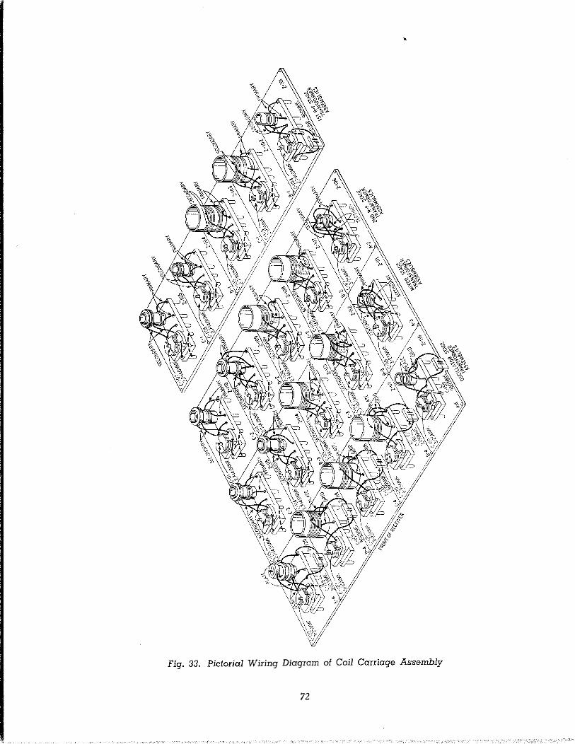
�
::;·
�·
0
;j
�·
� Q..
�
::::.;

,JOJ____,L---1\';--FUSE ilECEPTACLE J-i05
1
c,�:�� LAMP (Ul/ oOCOi ',�"'""''
' H.F. OSC.
0
"'
� 0
Fig. 34. PictO'rial Wiring Diagram of Top of Receiver Chassis
73
•
0


C-104
Z-101
C-158
C-116
Z-102
C-105
Z-103
C-106
Z-104
C-107
Z-105
C-165
R-105
C-179
R-131
C-180
C-183
C-182
R-121
R-124
R-112
C-171
C-170
R-133
C-192
C-186
R-137
11 T l'j'l �1'1' 1'111.'11 111\111 1 2 3 '.1
R-134 C-185 C-145 R-117 R-114 "' C-147 C-172
Fig. 38. Bottom View of RA0-3 Radio Receiver Showing 1st 1-F and A-F Sections
78

R-146
R-145
C-188
C-!18
Z-lll
C-117
Z-106
C-112
Z-112
Z-107
C-108
C-113
Z-108
C-109
z.n3
Z-109
�
C-110
Z-il4
C-114
R-136 C-197 C-152 R-155
' 11 I:! �l- I I' _1'1 �I' 11 I I! �I I I I f I I� Z-110 c.m
C-184 R-128 C-196 R-147 R-148
Z-115 C-115 C-156 Z-120 C-122
Fig. 39. Bottom View of RA0-3 Radio Receiver Showing Power Supply, Audio Output Stage and Coils
79

,__ ___ Z-121
X-113
C-202 T-102 ,--S��� X-112
'"' �� .·· . . «?;,; �''':5. �;;;; . .. I ""'
"'"� H-123
I T-101 � 'B'Jtliil! C.i�\�1IL'?��¥1�47§Yt:f<:5J.\?all/t5.111�: ':�:;}:\':.[' .'(.\ :;r:�:s-:;!:,.;' ,,�i��,iiiJiij
111!111 1111111 '1'1'1' l'j'l' l 2 3 4
�Q&
Fig. 40. Top View of Model RA0-3 Radio Receiver
80
11' H-125 1f
� � 0
M-101 R-158
E-219