nchrp report 350 - otw safetyotwsafety.com/.../mb42x72-jss-lcd-nchrp-report-350-test-3-71.pdf ·...
TRANSCRIPT

NCHRP Report 350 Test 3-71
Of the Multi-Barrier Model MB-42x72 JSS LCB
Longitudinal Channelizing Barricade System
TRC Inc. Test Number: 061221
Prepared by:
Transportation Research Center Inc.
10820 State Route 347
East Liberty, OH 43319
Final Report
December 2006 - January 2007
Prepared for:
Off the Wall Products, LLC
180 South 300 West, Suite 314
Salt Lake City, UT 84101


Technical Report Documentation Page 1. Report No. 061221
2. Government Accession No. 3. Recipient’s Catalog No.
4. Title and Subtitle NCHRP Report 350 Test 3-71
5. Report Date January 11, 2007
6. Performing Organization Code TRC
7. Author(s) Christopher Krouskop, Project Manager Transportation Research Center Inc.
8. Performing Organization Report No. Test Report 061221
9. Performing Organization Name and Address Transportation Research Center Inc.
10. Work Unit No. (TRAIS)
10820 State Route 347 East Liberty, OH 43319
11. Contract or Grant No.
12. Sponsoring Agency Name and Address Off the Wall Products, LLC 180 South 300 West, Suite 314
13. Type of Report and Period Covered Final Report January 2007
Salt Lake City, UT 48101
14. Sponsoring Agency Code
15. Supplemental Notes 16. Abstract Reported herein are the details and results of a full-scale crash test performed on the Multi-Barrier Safety Barricade Model MB-42x72 JSS LCB longitudinal channelizing barricade system. The crash test performed was NCHRP Report 350 test designation 3-71 involving a 2001 Suzuki Swift at a nominal speed of 100 km/h.
17. Key Words Longitudinal barricade, work zones, traffic control devices, roadside safety
18. Distribution Statement No restrictions, This document, if published, is available to the public through National Technical Information Service, 5285 Port Royal Road, Springfield, Virginia 22161
19. Security Classif. (of this report) Unclassified
20. Security Classif. (of this page) Unclassified
21. Number of Pages 117
22. Price
Form DOT F 1700.7 (8-72) Reproduction of completed page authorized

SI* (MODERN METRIC) CONVERSION FACTORS
APPROXIMATE CONVERSIONS TO SI UNITS Symbol When You Know Multiply by To Find Symbol
LENGTH in inches 25.4 millimeters mm ft feet 0.305 meters m yd yards 0.914 meters m mi miles 1.61 kilometers km
AREA in2 square inches 645.2 square millimeters mm2
ft2 square feet 0.093 square meters m2
yd2 square yards 0.836 square meters m2
ac acres 0.405 hectares ha mi2 square miles 2.59 square kilometers km2
VOLUME fl oz fluid ounces 29.57 milliliters mL gal gallons 3.785 liters L ft3 cubic feet 0.028 cubic meters m3
yd3 cubic yards 0.765 cubic meters m3
NOTE: Volumes greater than 1000l shall be shown in m3
MASS oz ounces 28.35 grams g lb pounds 0.454 kilograms kg
T
short tons (2000lb)
0.907
Megagrams (or "metric ton")
Mg (or "t")
TEMPERATURE (exact) °F Fahrenheit 5(F-32)/9 Celsius °C
ILLUMINATION fc foot-candles 10.76 lux lx fl foot-Lamberts 3.426 candela/m2 cd/m2
FORCE and PRESSURE or STRESS lbf poundforce 4.45 newtons N
lbf/in2
poundforce per square inch
6.89
kilopascals
kPa
*SI is the symbol for the International System of Units.Appropriate rounding should be made to comply with Section 4 of ASTM E380.
APPROXIMATE CONVERSIONS FROM SI UNITS Symbol When You Know Multiply by To Find Symbol
LENGTH mm millimeters 0.039 inches inm meters 3.28 feet ft m meters 1.09 yards ydkm kilometers 0.621 miles mi
AREA mm2 square millimeters 0.0016 square inches in2
m2 square meters 10.764 square feet ft2
m2 square meters 1.195 square yards yd2
ha hectares 2.47 acres ac km2 square kilometers 0.386 square miles mi2
VOLUME mL milliliters 0.034 fluid ounces fl oz L liters 0.264 gallons gal m3 cubic meters 35.71 cubic feet ft3
m3 cubic meters 1.307 cubic yards yd3
MASS
g grams 0.035 ounces ozkg kilograms 2.202 pounds lb
Mg (or "t")
megagrams (or "metric ton")
1.103
short tons (2000lb) T
TEMPERATURE (exact) °C Celsius 1.8C + 32 Fahrenheit °F
ILLUMINATION lx lux 0.0929 foot-candles fccd/m2 candela/m2 0.2919 foot-Lamberts fl
FORCE and PRESSURE or STRESS N newtons 0.225 poundforce lbf
kPa
kilopascals
0.145
poundforce per square inch lbf/in2
(Revised September 1995)

i
Table of Contents
Section Title Page
1.0 Introduction 1-1 Purpose 1-2
2.0 Study Approach 2-1 Test Article 2-2 Customer Test Set-up Requirements 2-2 Actual test Set-up 2-2 Crash Test Conditions 2-7 Crash Test and Data Analysis Procedures 2-10 Electronic Instrumentation and Data Processing 2-10 Anthropomorphic Dummy Instrumentation 2-11 Photographic Instrumentation and Data Processing 2-11 Description of Timing Marks on TRC Inc. Digital High- Speed Cameras 2-11 Test Vehicle Propulsion and Guidance 2-11
3.0 Crash Test Results 3-1 NCHRP Report 350 Test Designation 3-71 3-2 Test Vehicle 3-2 Weather Conditions 3-2 Test Description 3-2 Damage to Test Installation 3-4 Damage to Test Vehicle 3-13 Occupant Risk Values 3-13 Summary Sheet for Crash Test Data 3-15
4.0 Summary of Findings and Conclusions 4-1 Summary of Findings 4-2 Conclusions 4-2 Performance Evaluation Summary for Impacting Vehicle 4-3
References 5-1
Appendix A Photographs A-1
Appendix B Data Plots B-1
Appendix C Miscellaneous Test Data C-1
Appendix D Multi-Barrier Model MB-42x72 JSS LCB Channelizing Barricade System Specifications D-1

1-1
Section 1.0
INTRODUCTION

1-2
PURPOSE
This test was conducted to obtain vehicle crashworthiness data to evaluate the
performance of the Multi-Barrier Model MB-42x72 JSS LCB channelizing barricade system
relative to the work zone traffic control device requirements of the Federal Highway
Administration’s National Cooperative Highway Research Program Report 350 (NCHRP
350) “Recommended Procedures for the Safety Performance Evaluation of Highway
Features.”

2-1
Section 2.0
STUDY APPROACH

2-2
TEST ARTICLE
The Multi-Barrier Model MB-42x72 JSS LCB longitudinal channelizing barricade
system consisted of ten (10) water-filled UV-resistant polyethylene barricades is to be tested
to the NCHRP 350 test level 3-71 guidelines.
Each polyethylene barricade consists of two equal chambers that are manufactured from
High Density Polyethylene (HDPE) plastic. Each barricade weighs approximately 19.3 kg
(42.5 lbs) empty and can be filled with up to 90 gallons (701.0 kg) of water in each of the twi
chambers.
Customer Test Set-up Requirements
The Multi-Barrier Model MB-42x72 JSS LCB channelizing barricade system consisting
of 10 interlocking barricades, is to be positioned in a longitudinal line such that the right
front corner of the impacting 820C vehicle will strike the center of the fifth barricade of the
system at a 20º angle. Each chamber of each individual barricade is to be filled with
approximately 5.38 gallons (20.4 kg) of water.
The overall length of the ten (10) interlocking barricade system is to be approximately
18.3 meters (see Figure 1).
Actual Test Set-up
The Multi-Barrier Model MB-42x72 JSS LCB channelizing barricade system, that was
tested to the NCHRP Report 350 test level 3-71 guidelines, was positioned in a longitudinal
line such that the right front corner of the impacting 820C vehicle struck the center of the
fifth barricade of the system.

2-3
Each chamber of each individual barricade was filled with approximately 5.38 gallons
(20.4 kg) of water. The overall length of the ten (10) interlocking barricade system was
approximately 18.3 meters (see Figure 1).
Details of the Multi-Barrier Model MB-42x72 JSS channelizing barricade system are
shown in Figure 1, Figure 2, and Appendix D.

Type: Multi-Barrier Channelizing Barricade Model MB-42x72 JSS LCB
Colors: Orange or White
Composition: High Impact UV Resistant High Density Polyethylene
Size: Height: 42” / 107 cm Length: 72” / 183 cm Width: 24” / 61 cm Wall: 0.22” / 5.6 mm Mass: 42.5 lb. / 19.3 kg (empty) Mass: 1545.5 lb. / 701.0 kg (full)
Scope of service: Rapidly deployable traffic / security barricade. Enhances security
and safety in less time than constructing sandbag structures or moving concrete road barriers. Weighing only 42.5 pounds, the barricade can be installed manually and once positioned each of the two compartments can be filled with up to 90 gallons of water. Compatible with lights, signage, and stanchions and fencing. Stackable and easy to ship and store. Made from High Density Polyethylene Plastic. Can form a tamper proof inseparable wall in any configuration.
Figure 1. Details of the Multi-Barrier Model MB-42x72 JSS LCB
2-4

Directionof Travel
Impact Point
Figure 1. Details of the Multi-Barrier Model MB-42x72 JSS LCB (continued)
2-5

Figure 2. Multi-Barrier Model MB-42x72 JSS LCB Barricade System before test 061221.
2-6

2-7
CRASH TEST CONDITIONS NCHRP Report 350 Test Designation
According to NCHRP Report 350, there are two tests that are required to evaluate
longitudinal barriers, such as the Multi-Barrier Model MB-42x72 JSS LCB portable water-
filled barricade, to test level two (TL-3) as described below.
NCHRP Report 350 test designation 3-701: This test involves a 700-kg passenger car
impacting the critical impact point (CIP) of the length of need (LON) of the work-zone
traffic control device at a nominal speed of 35 km/h and angle and 20 degrees. The
critical impact point (CIP) and length of need (LON) of the test article are determined
through discussion between the manufacturer and FHwA. The purpose of this test is to
evaluate the performance of the test article, at the pre-approved LON, based upon the
breakaway, fracture or yielding mechanism of the device through the evaluation criteria
(including occupant risk) for test level 3-70.
NCHRP Report 350 test designation 3-71: This test involves an 820-kg passenger car
impacting the critical impact point (CIP) of the length of need (LON) of the work-zone
traffic control device, such as plastic drums used as channelizing devices, at a nominal
speed of 100 km/h and angle and 20 degrees. The critical impact point (CIP) and length
of need (LON) of the test article are determined through discussion between the
manufacturer and FHwA. The purpose of this test is to evaluate the performance of the
test article, at the pre-approved LON, based upon the evaluation criteria (including
occupant risk) for test level 3-71; with the exception of occupant impact velocities, which
will be based upon the evaluation criteria for test level 3-10 (longitudinal barriers).
FHWA Safety Questions and Answers about Crash Testing of Work Zone Safety
Appurtenances: Work zone traffic control devices individually weighing 45 kg (empty)
have no pretext of being a barrier that can redirect an errant vehicle; therefore, the
evaluation criteria sub-part H and I, found in Table 5.1 of the NCHRP Report 350 is
optional. 1 NCHRP Report 350 TL 3-70 can be omitted when it is clearly determined that test level
3-71 is more critical.

2-8
NCHRP Report 350 test designation 3-71 was performed on the Multi-Barrier Model
MB-42x72 JSS LCB channelizing barricade system and the details and results are reported
herein. Off the Wall Products, LLC specified the Critical Impact Point (CIP) chosen for this
test. The CIP was requested to be the center of barricade 5.
The crash test and data analysis procedures were in accordance with the guidelines
presented in NCHRP Report 350. Brief descriptions of these procedures are presented
below:
Evaluation Criteria
The crash test performed was evaluated in accordance with the criteria presented in
NCHRP Report 350, with special emphasis on longitudinal channelizing devices. As stated
in NCHRP Report 350, “Safety performance of a highway appurtenance cannot be measured
directly but can be judged on the basis of three factors: structural adequacy, occupant risk,
and vehicle trajectory after collision.” Accordingly, the following safety evaluation criteria
from table 5.1 of NCHRP Report 350 were used to evaluate the crash test reported herein.
• Structural Adequacy
B. The test article should readily activate in a predictable manner by breaking
away, fracturing, or yielding.
• Occupant Risk
D. Detached elements, fragments or other debris from the test article should not
penetrate or show potential for penetration of the occupant compartment, or
present an undue hazard to other traffic, pedestrians, or personnel in a work
zone. Deformation of, or intrusions into, the occupant compartment that could
cause serious injuries should not be permitted.

2-9
E. Detached elements, fragments or other debris from the test article, or vehicular
damage should not block the driver’s vision or otherwise cause the driver to lose
control of the vehicle.
F. The vehicle should remain upright during and after collision although moderate
roll, pitching and yawing are acceptable.
H. Occupant impact velocities should satisfy the following1:
Occupant Impact Velocity Limits (m/s)
Component Preferred Maximum
Longitudinal and Lateral 9 12
I. Occupant ride down accelerations should satisfy the following:
Occupant Ridedown Acceleration Limits (G’s)
Component Preferred Maximum
Longitudinal and Lateral 15 20
J. (Optional) Hybrid III dummy. Response should conform to evaluation criteria
of Part 571.208, Title 49 if Code of Federal Regulation, Chapter V (10-1-88
Edition).
• Vehicle Trajectory
K. After collision it is preferable that the vehicle’s trajectory not intrude into
adjacent traffic lanes.
N. Vehicle trajectory behind the test article is acceptable.
1 FHwA requested the testing facility (TRC Inc.) to use the longitudinal barrier criteria for
this portion of the evaluation criteria for longitudinal channelizing barricades.

2-10
CRASH TEST AND DATA ANALYSIS PROCEDURES
The crash test and data analysis procedures were in accordance with guidelines presented
in NCHRP Report 350. Brief descriptions of these procedures are presented as follows.
Electronic Instrumentation and Data Processing
The impacting vehicle was instrumented with three angular rate transducers to measure
roll, pitch and yaw; a primary and redundant set of triaxial accelerometers near the vehicle
center-of-gravity to measure longitudinal, lateral, and vertical acceleration levels.
The electronic signals from the accelerometers and transducers were collected by means
of a self-contained onboard digital data acquisition system at a rate of 10,000 samples per
second. The onboard digital data acquisition system was connected by an umbilical cable to
the data acquisition room only for pre-test setup and checkout and post-test data
downloading.
Each data channel was filtered to SAE J211 OCT88 Channel Class 1000. Immediately
preceding each test, all data channels were checked and balanced by the data acquisition
system software. The data was downloaded from the onboard digital storage to the data
acquisition room by an umbilical cable, which is connected from the test vehicle to the
personal computer in the data acquisition room. Following initial verification of the data
signals, fiber optic cable transferred the data to the digital computer for all subsequent digital
data processing.
Subsequent digital filtering of the data was performed. As specified in NCHRP 350, the
filters conform to the Society of Automotive Engineers Recommended Practice SAE J211
OCT88.

2-11
Anthropomorphic Dummy Instrumentation
An uninstrumented anthropomorphic dummy was used for test 3-71, performed on
December 21, 2006.
Photographic Instrumentation and Data Processing
Photographic coverage of the test included eight (8) high-speed digital cameras: two (2)
overhead with a field of view perpendicular to the ground and directly over the impact point;
a third placed to have a field of view perpendicular to the impact point; a fourth placed to
have a field of view perpendicular to and upstream of the impact point; a fifth placed to have
a narrow field of view perpendicular to the impact point; a sixth placed to have a field of
view upstream to the impact point on the non-impact side; and a seventh placed to have a
field of view upstream to the impact point on the impact side. A pressure sensitive tape
switch was positioned on the impacting vehicle to indicate the instant of contact with the
MB-42x72 JSS LCB channelizing barricade system. The views from these high-speed
cameras were analyzed on a digital motion picture image analyzer to observe phenomena
occurring during the collision and to obtain time-event, displacement and angular data. One
(1) Canon real-time motion picture camera was used to record and document the conditions
of the test vehicle and installation before and after the test and to record and document the
impact event. A still camera was used to record and document conditions of the test vehicle
and installation before and after the test.
Description of Timing Marks on TRC Inc. Digital High-Speed Cameras
All TRC Inc. high-speed cameras are equipped with timing displays. When converted to
AVI files, this information is displayed in the upper left corner of the picture.
Test Vehicle Propulsion and Guidance
The test vehicle was towed into the test article by towing cables attached to each side of the
vehicle’s front suspension and connected to the drive cable by a frangible skate assembly. The
frangible skate assembly was attached to a monorail providing lateral guidance while towing the

2-12
vehicle. The test vehicle’s steering wheel was unlocked to allow proper tracking of vehicle
while attached to the monorail. At a predetermined point prior to impact, the frangible skate
assembly struck a block of steel driving the wedge portion of the assembly through the
assembly’s channels. This action simultaneously released the tension to the drive cable, the
vehicle towing cables, and the attachment to the monorail. This method allowed the vehicle to
free-roll to the impact point without influence from the propulsion system.

3-1
Section 3.0
Crash Test Results

3-2
NCHRP Report 350 Test Designation 3-71
Test Vehicle
A 2001 Suzuki Swift passenger car was used for this crash test. The test inertial weight
was 844.8 kg and the gross static weight of the vehicle was 919.6 kg. The height to the lower
edge of the vehicle bumper was 393 mm and it was 508 mm to the upper edge of the bumper.
Additional dimensions and information on the vehicle are given on page 3-8. The vehicle
was directed into the installation using the tow system, and was released to be freewheeling
and unrestrained just prior to impact.
Weather Conditions
The crash test was performed the morning of December 21, 2006. The pavement was
wet and the weather conditions at the time of testing were as follows:
Wind speed: 3.2 km/h
Wind direction: 76° NE
Temperature: 5.6° C
Relative humidity: 89 percent
Barometric pressure: 200.1 kPa
Test Description
The vehicle, traveling at 100.5 km/h, impacted the center of barricade 5 of the Multi-
Barrier Model MB-42x72 JSS LCB channelizing barricade system at 20° with the vehicle’s
right front fender (see Figure 3). The vehicle continued in a forward direction and remained
in momentary contact with barricade 5. At approximately 40 milliseconds after time zero
barricade 6 was pushed to the right and backwards slightly, as the vehicle, remaining in
contact with barricade 5, continued in a forward direction. At approximately 54 milliseconds
after time zero, barricade 5 started to become disconnected from barricades 4 and 6. At
approximately 68 milliseconds after time zero the vehicle’s right front fender impacted the
center of barricade 6, while barricade 5 was pushed slightly to the right and parallel to the
vehicle’s forward direction. At approximately 90 milliseconds after time zero the vehicle

3-3
continued in a forward direction pushing barricade 6 such that barricade 6 was bent into an
approximate 30 degree shape while being disengaged from barricade 5. At approximately
100 milliseconds the vehicle’s left front bumper area impacted the end of barricade 7; while
the vehicle’s right front bumper remained in contact with barricade 6, pushing it forward and
slightly to the right. At approximately 110 milliseconds after time zero the vehicle’s right
front wheel started to ride up barricade 6 as the vehicle moved forward. The vehicle’s right
side wheels remained airborne from approximately 110 to 860 milliseconds. At
approximately 140 milliseconds after time zero, barricade 6 became disengaged from
barricade 7 as the vehicle continued forward. From approximately 144 to 230 milliseconds,
the vehicle continued forward, pushing barricade 7 into barricade 8 thus causing barricade 8
to move sideways and into barricade 9 in a jagged saw-tooth fashion. At approximately 260
milliseconds after time zero, barricades 8 and 9 separated from each other as the vehicle
continued to move forward. At approximately 320 milliseconds after time zero, barricade 9
separated from barricade 10, as the vehicle continued forward. At approximately 400
milliseconds after time zero, barricade 8 was pushed into barricade 10 by the momentum of
the vehicle’s forward motion. As the vehicle continued in a forward direction, barricade 7
remained in contact with the vehicle’s front bumper area. From approximately 450 to 900
milliseconds after time zero, the vehicle continued to displace barricades 6 and 7 to the right
and barricades 8, 9 and 10 to the left as the vehicle continued forward. At approximately
1100 milliseconds after time zero all of the vehicle’s wheels came back to the ground, while
barricade 7 was propelled away from and to the right of the vehicle. From approximately
1160 to 4800 milliseconds after time zero, the vehicle continued forward, prior to being
stopped by TRC Inc.’s secondary back-up breaking system. The vehicle came to rest at
approximately 4800 milliseconds in a straight line from the initial impact direction. The
vehicle remained upright throughout the test event. Maximum displacement of the vehicle
into the Multi-Barrier Model MB-42x72 JSS LCB channelizing barricade system was
approximately 88.4 meters longitudinally and 1.2 meters laterally to the right from the
original impact point. Maximum roll was -23.2 degrees. Maximum pitch was 6.2 degrees.
Maximum yaw was -22.1 degrees.

3-4
Damage to Test Installation
One of the ten individual barricade sections that made up the Multi-Barrier Model MB-
42x72 JSS LCB channelizing barricade system, barricade 5, was displaced in the immediate
impact zone as shown in Appendix A, Figures A-37, A-39, A-41, A-43, A-45, A-47 and
A-50.
Five of the ten individual barricade sections that made up the Multi-Barrier Model MB-
42x72 JSS LCB channelizing barricade system, barricades 6, 7, 8, 9 and 10, were displaced
outside of the immediate impact zone as shown in Appendix A, A-37, A-39, A-41, A-43,
A-45, A-47, A-50, A-56, A-57, A-58, A-59, A-60, A-67, A-68, A-69, A-70 and A-71.
Individual barricade sections 5, 6, 7, and 8 incurred damage to their overall outer shell
sidewalls, being scored or ruptured, as shown in Appendix A, Figures A-57, A-58, A-61, A-
62, A-63, A-64, and A-65.

Figure 3. Impacting vehicle/ MB-42x72 JSS LCB channelizing barricade system geometrics for test 061221.
3-5
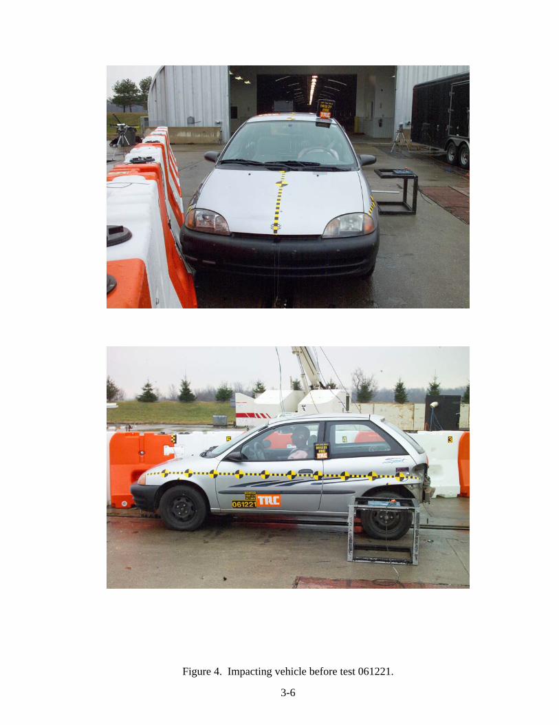
Figure 4. Impacting vehicle before test 061221.
3-6

Figure 4. Impacting vehicle before test 061221. (continued)
3-7

Date: 12/21/06 Test No: 061221 Vin No: 2S2AB21H016602815 Make: Suzuki
Model: Swift Year: 2001 Odometer: 103,220 miles GVW: 1190 kg
Tire Size: P155/80R13 Tire Inflation Pressure: Front 32 psi / Rear 32 psi Tread Type: N/A
Mass Distribution (kg) LF 301.2 RF 265.6 LR 181.4 RR 171.4 Describe any damage to vehicle prior to test:
D
CLO
H
EMM
M
21
C
F
GB
Q
L
NWheelTrack
WheelTrackVehicleA
KJ
PTire Dia.Test Inertial C.M.
Wheel Dia.
Engine Type: Transverse Engine Size: 1.3 L Transmission Type:
X Auto Manual Optional Equipment: N/A
Dummy Data: Type: Hybrid II 50th Mass: 74.8 kg Seat Position: Left front
Geometry - (mm)
A 1585 D 1405 G 905 K 508 N 1400 Q 370
B 820 E 605 H N/A L 98 O 1360
C 2360 F 3785 J 550 M 393 P 555 Mass - (kg) Curb Test Inertial1 Gross Static
M1 554.4 528.2 566.8
M2 306.2 316.6 352.8
MT 860.6 844.8 919.6
Figure 5. Vehicle properties for test 061221
1 The following components were removed to achieve test inertial weight: tail lights, hubcaps, hatch seal, rear seat belt assemblies, and rear fascia.
3-8

0.000 s
0.030 s
0.060 s
0.090 s
Figure 6. Sequential photographs for test 061221 (overhead and perpendicular views).
3-9

0.120 s
0.180 s
0.240 s
0.300 s
Figure 6. Sequential photographs for test 061221 (overhead and perpendicular views) (continued).
3-10

0.450 s
0.600 s
0.800 s
3Figure 6. Sequential photographs for test 061221 (overhead and perpendicular views) (continued).
3-11

Figure 7. MB-42x72 JSS LCB channelizing barricade system after test 061221
3-12
3-13
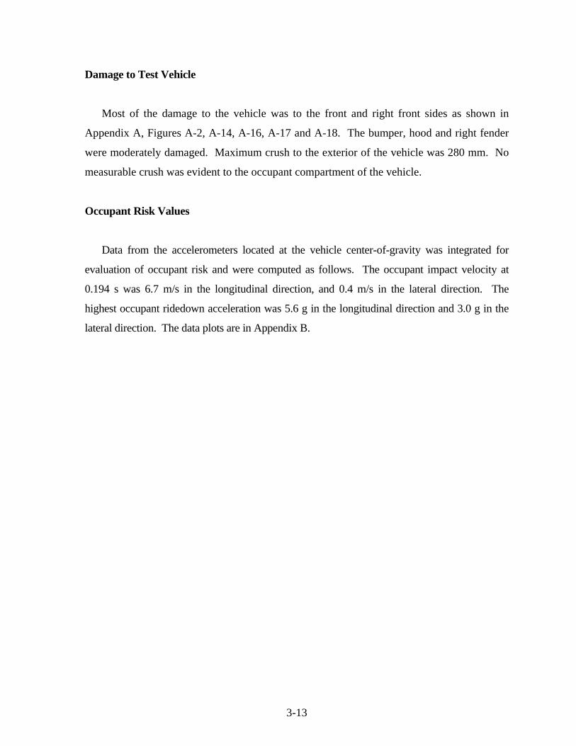
Damage to Test Vehicle
Most of the damage to the vehicle was to the front and right front sides as shown in
Appendix A, Figures A-2, A-14, A-16, A-17 and A-18. The bumper, hood and right fender
were moderately damaged. Maximum crush to the exterior of the vehicle was 280 mm. No
measurable crush was evident to the occupant compartment of the vehicle.
Occupant Risk Values
Data from the accelerometers located at the vehicle center-of-gravity was integrated for
evaluation of occupant risk and were computed as follows. The occupant impact velocity at
0.194 s was 6.7 m/s in the longitudinal direction, and 0.4 m/s in the lateral direction. The
highest occupant ridedown acceleration was 5.6 g in the longitudinal direction and 3.0 g in the
lateral direction. The data plots are in Appendix B.

Figure 8. Impacting vehicle after test 061221.
3-14

0.000 s 0.090 s 0.180 s 0.300 s 0.450 s
88.4 m
OriginalImpactPoint
1.2 m
General Information Test Agency Transportation Research Center Inc. (TRC Inc.) Test No. 061221 Date December 21, 2006 Test Article Type Longitudinal Channelizing Barricade Name or Manufacturer MB-42x72 JSS LCB by Off the Wall Products, LLC Size and/or dimension 10 individual portable polyethylene and material of key water filled barricades, each being elements 107 cm (H) 182.9 cm (L) x 61 cm (W) Soil Type and Condition N/A Test Vehicle Type Production Model Designation 820C Model 2001 Suzuki Swift Mass (kg) Curb 860.6 Test Inertial 844.8 Dummy(s) 74.8 Gross Static 919.6
Impact Conditions Speed (km/h) 100.5 Angle (deg) 20 Exit Conditions Speed (km/h) N/A Angle (deg) N/A Occupant Risk Values Impact Velocity (m/s) x-direction 6.7 y-direction 0.4 THIV (optional) 24.38 Ridedown Acceleration (g’s) x-direction 5.6 y-direction 3.0 PHD (optional) 5.59 g ASI (optional) 0.48 Max. 0.050 –s Average (g’s) x-direction -5.7 g y-direction 1.4 g z-direction -2.4 g
Test Article Deflections (m) Dynamic 13.3 Permanent 13.3 Vehicle Damage Exterior VDS N/A CDC 01FZEW1 Interior OCDI FS0000000 Maximum Exterior Vehicle Crush (mm) 280 Max. Occ. Compart. Deformation (mm) 0 Post-Impact Vehicular Behavior Maximum Roll Angle (deg) -23.2 Maximum Pitch Angle (deg) 6.2 Maximum Yaw Angle (deg) -22.1
Vehicle Trajectory Post Test The impacting
vehicle’s final most outer left trajectory stayed within twelve feet of the barrier. Assuming that the barrier was at the edge of the lane, the vehicle would have stayed within a 12-foot lane width.
Figure 9. Summary of results for test 061221

-500 0 500 1000 1500 2000 2500 3000
-12.5
-10
-7.5
-5
-2.5
0
2.5
5
10VEHCCG0000ACXD
Time [ms]Max. Value4.48 g at 840.00 ms
Min. Value-10.35 g at 75.60 ms
NCHRP350 Test 3-71 on Multi-Barrier Model MB-42x72 JSS LCBVehicle CG X-Axis Acceleration
TRC Inc. Test Lab: CTFCustomer: Off the Wall Products, LLCTest Number: 061221
Date: 12/21/2006Time: 11:11
Filter: CFC_60
Acc
ele r
atio
n [ g
]

-500 0 500 1000 1500 2000 2500 3000
-6
-4
-2
0
2
4
6
10VEHCCG0000ACYD
Time [ms]Max. Value4.80 g at 842.10 ms
Min. Value-5.01 g at 19.30 ms
NCHRP350 Test 3-71 on Multi-Barrier Model MB-42x72 JSS LCBVehicle CG Y-Axis Acceleration
TRC Inc. Test Lab: CTFCustomer: Off the Wall Products, LLCTest Number: 061221
Date: 12/21/2006Time: 11:11
Filter: CFC_60
Acc
ele r
atio
n [ g
]

-500 0 500 1000 1500 2000 2500 3000
-12.5
-10
-7.5
-5
-2.5
0
2.5
5
7.5
10VEHCCG0000ACZD
Time [ms]Max. Value6.96 g at 840.30 ms
Min. Value-11.10 g at 848.20 ms
NCHRP350 Test 3-71 on Multi-Barrier Model MB-42x72 JSS LCBVehicle CG Z-Axis Acceleration
TRC Inc. Test Lab: CTFCustomer: Off the Wall Products, LLCTest Number: 061221
Date: 12/21/2006Time: 11:11
Filter: CFC_60
Acc
ele r
atio
n [ g
]

4-1
Section 4.0
Summary of Findings and Conclusions

4-2
Summary of Findings
During test 061221 (NCHRP Report 350 TL 3-71), there were six detached individual
barricades, and four individual barricades that exhibited damage from the Multi-Barrier Model
MB-42x72 JSS LCB channelizing barricade system, with each individual barricade weighing
less than 45 kg empty. There were no detached elements from the impacting vehicle or
barricade system to penetrate the occupant compartment of the impacting vehicle or to present
hazards to others in the area. There was no measurable deformation into the occupant
compartment. The ridedown accelerations were within the recommended limits for the
impacting vehicle. The occupant impact velocity was within the stated limits when evaluating
the Multi-Barrier Model MB-42x72 JSS LCB channelizing barricade system to the
longitudinal barrier criteria for velocity. The Multi-Barrier Model MB-42x72 JSS LCB
channelizing barricade system performed acceptably per current NCHRP Report 350 TL 3-71
test standards, which require the test article to activate in a predictable manner by breaking
away, fracturing, or yielding in response to the test vehicle. The channelizing barricade system,
used as a work zone traffic control device, allowed the test vehicle to penetrate the barrier
system. The impacting vehicle’s final resting place intruded into the adjacent pedestrian area to
the right of the barricade’s initial pre-test placement location.
Conclusions
Test 061221, with the 820C vehicle, appeared to meet all NCHRP Report 350 evaluation
criteria for test designation 3-711. The impacting vehicle remained upright during and after
the impact. The impacting vehicle was not contained by the barricade system, which was
tested as a work zone traffic control device. The impacting vehicle remained within 12 feet
laterally of the barricade. There were multiple detached barricade elements however none
penetrated the vehicle’s occupant area. All occupant risk factors were within the limits
specified in NCHRP Report 350.
1 As referenced in the American Association of State Highway and Transportation Officials (AASHTO) publication “A Policy on the Geometric Design of Highways and Streets, 2001”, Chapter 4, Page 315.

4-3
Performance Evaluation Summary for Impacting Vehicle
Test Agency: Transportation Research Center Inc.
Test No.: 061221, NCHRP Report 350 Test 3-71 Test Date: 12/21/06
NCHRP Report 350 Evaluation Criteria Test Results Assessment Structural Adequacy B. The test article should readily activate in a
predictable manner by breaking away, fracturing, or yielding.
The MB-42x72 JSS LCB channelizing barricade system broke away in a predictable manner.
Pass
Occupant Risk D. Detached elements, fragments or other debris from the test article should not penetrate or show potential for penetrating the occupant compartment, or present an undue hazard to other traffic, pedestrians, or personnel in a work zone. Deformations of, or intrusions into, the occupant compartment that could cause serious injuries should not be permitted.
The MB-42x72 JSS LCB channelizing barricade system remained contained in the immediate impact location, did not allow debris to penetrate the occupant compartment, or present hazard to the immediate area. There was no deformation into the occupant compartment.
Pass
E. Detached elements, fragments or other debris from the test article, or vehicular damage should not block the driver’s vision or otherwise cause the driver to lose control of the vehicle.
The MB-42x72 JSS LCB channelizing barricade system did not appear to block the driver’s vision.
Pass
F. The vehicle should remain upright during and after collision although moderate roll, pitching and yawing are acceptable.
The impacting vehicle remained upright during and after the collision.
Pass
H. Occupant impact velocities should satisfy the following1:
Occupant Impact Velocity Limits (ms) Component Preferred Maximum
Longitudinal and Lateral
9 12
Longitudinal Velocity 6.7 m/s
Lateral Velocity 0.4 m/s
Met
Criteria1
I. Occupant ridedown accelerations should satisfy the following:
Occupant Ridedown Acceleration Limits (G’s) Component Preferred Maximum Longitudinal And Lateral
15 20
Longitudinal Ridedown Acceleration: 5.6 g’s Lateral Ridedown Acceleration: 3.0 g’s
Pass
J. (Optional) Hybrid III dummy. Response should conform to evaluation criteria of Part 571.208, Title 49 of Code of Federal Regulation, Chapter V (10-1-88 Edition)
Dummy was not instrumented
Not
Applicable
1 FHwA requested the testing facility (TRC Inc.) to use the longitudinal barrier criteria for
this portion of the evaluation criteria for longitudinal channelizing barricades.

4-4
Performance Evaluation Summary for Impacting Vehicle, Continued
Test Agency: Transportation Research Center Inc.
Test No.: 061221, NCHRP Report 350 Test 3-71 Test Date: 12/21/06 Vehicle Trajectory K. After collision, it is preferable that the vehicle’s
trajectory not intrude into adjacent traffic lanes.
The impacting vehicle’s final most outer right trajectory stayed within twelve feet of the barricade. Assuming that the barricade was at the edge of the lane, the vehicle would have stayed within a 12-foot lane width.1
Pass
N. Vehicle trajectory behind the test article is acceptable.
The impacting vehicle’s final trajectory extended behind the test article.
Pass
1 As referenced in the American Association of State Highway and Transportation Officials (AASHTO) publication “A Policy on the Geometric Design of Highways and Streets, 2001”, Chapter 4, Page 315.

5-1
References 1. H.E. Ross, Jr., D.L. Sicking, R.A. Zimmer, and J.D. Michie, “Recommended
Procedures for the Safety Performance Evaluation of Highway Features,” NCHRP Report 350, Transportation Research Board, Washington, D.C., 1995.

A-1
Appendix A
NCHRP 350 3-71 Test Photographs

A-2
List of Photographs
Title Figure
Pre-Test Vehicle Front with Channelizing Barricade View A-1
Post-Test Vehicle Front - Final Resting Position View A-2
Pre-Test Vehicle Left Front with Channelizing Barricade View A-3
Post-Test Vehicle Left Front - Final Resting Position View A-4
Pre-Test Vehicle Left Side with Channelizing Barricade View A-5
Post-Test Vehicle Left Side - Final Resting Position View A-6
Pre-Test Vehicle Left Rear with Channelizing Barricade View A-7
Post-Test Vehicle Left Rear - Final Resting Position View A-8
Pre-Test Vehicle Rear with Channelizing Barricade View A-9
Post-Test Vehicle Rear - Final Resting Position View A-10
Pre-Test Vehicle Right Rear with Channelizing Barricade View A-11
Post-Test Vehicle Right Rear - Final Resting Position View A-12
Pre-Test Vehicle Right Side View A-13
Post-Test Vehicle Right Side - Final Resting Position View A-14
Pre-Test Vehicle Right Front View A-15
Post-Test Vehicle Right Front - Final Resting Position View A-16
Post-Test Vehicle Damage - View 1 A-17
Post-Test Vehicle Damage - View 2 A-18
Pre-Test Front Underbody View A-19
Post-Test Front Underbody View A-20
Pre-Test Mid Front Underbody View A-21
Post-Test Mid Front Underbody View A-22
Pre-Test Mid Underbody View A-23
Post-Test Mid Underbody View A-24
Pre-Test Mid Rear Underbody View A-25
Post-Test Mid Rear Underbody View A-26
Pre-Test Rear Underbody View A-27
Post-Test Rear Underbody View A-28

A-3
List of Photographs, Cont’d
Title Figure
Pre-Test Engine Compartment View A-29
Pre-Test Engine Compartment View A-30
Pre-Test Overhead Impact Alignment View A-31
Pre-Test Front Impact Alignment View A-32
Pre-Test Left Front Impact Alignment - View 1 A-33
Pre-Test Left Front Impact Alignment - View 2 A-34
Pre-Test Channelizing Barricade Upstream Overall View A-35
Pre-Test Channelizing Barricade Impact Side Upstream Overall View A-36
Post-Test Channelizing Barricade Impact Side Upstream Overall View A-37
Pre-Test Channelizing Barricade Impact Side Overall View A-38
Post-Test Channelizing Barricade Impact Side Overall View A-39
Pre-Test Channelizing Barricade Impact Side Downstream Overall - View 1 A-40
Post-Test Channelizing Barricade Impact Side Downstream Overall - View 1 A-41
Pre-Test Channelizing Barricade Impact Side Downstream Overall - View 2 A-42
Post-Test Channelizing Barricade Impact Side Downstream Overall - View 2 A-43
Pre-Test Channelizing Barricade Downstream Overall View A-44
Post-Test Channelizing Barricade Downstream Overall View A-45
Pre-Test Channelizing Barricade Non-Impact Side Downstream Overall View A-46
Post-Test Channelizing Barricade Non-Impact Side Downstream Overall View A-47
Pre-Test Channelizing Barricade Non-Impact Side Overall View A-48
Pre-Test Channelizing Barricade Non-Impact Side Upstream Overall View A-49
Post-Test Channelizing Barricade Non-Impact Side Upstream Overall View A-50
Post-Test Barricade 1 View A-51
Post-Test Barricade 2 View A-52
Post-Test Barricade 3 View A-53
Post-Test Barricade 4 View A-54
Post-Test Barricade 5 View A-55
Post-Test Barricade 6 View A-56

A-4
List of Photographs, Cont’d
Title Figure
Post-Test Barricade 7 View A-57
Post-Test Barricade 8 View A-58
Post-Test Barricade 9 View A-59
Post-Test Barricade 10 View A-60
Post-Test Damage to Barricade 5 - View 1 A-61
Post-Test Damage to Barricade 5 - View 2 A-62
Post-Test Damage to Barricade 6 - View 1 A-63
Post-Test Damage to Barricade 6 - View 2 A-64
Post-Test Damage to Barricade 8 View A-65
Post-Test Channelizing Barricade Resting Position - View 1 A-66
Post-Test Channelizing Barricade Resting Position - View 2 A-67
Post-Test Channelizing Barricade Resting Position - View 3 A-68
Post-Test Channelizing Barricade Resting Position - View 4 A-69
Post-Test Channelizing Barricade Resting Position - View 5 A-70
Post-Test Channelizing Barricade and Vehicle Resting Positions View A-71
Vehicle Certification Label View A-72
Vehicle Tire Information Label A-73
Post-Test Primary Digital Light Trap Readout View A-74
Post-Test Secondary Digital Light Trap Readout View A-75

Figure A-1 Pre-Test Vehicle Front with Channelizing Barricade View
Figure A-2 Post-Test Vehicle Front - Final Resting Position View

Figure A-3 Pre-Test Vehicle Left Front with Channelizing Barricade View
Figure A-4 Post-Test Vehicle Left Front - Final Resting Position View

Figure A-5 Pre-Test Vehicle Left Side with Channelizing Barricade View
Figure A-6 Post-Test Vehicle Left Side - Final Resting Position View

Figure A-7 Pre-Test Vehicle Left Rear with Channelizing Barricade View
Figure A-8 Post-Test Vehicle Left Rear - Final Resting Position View

Figure A-9 Pre-Test Vehicle Rear with Channelizing Barricade View
Figure A-10 Post-Test Vehicle Rear - Final Resting Position View

Figure A-11 Pre-Test Vehicle Right Rear with Channelizing Barricade View
Figure A-12 Post-Test Vehicle Right Rear - Final Resting Position View

Figure A-13 Pre-Test Vehicle Right Side View
Figure A-14 Post-Test Vehicle Right Side - Final Resting Position View
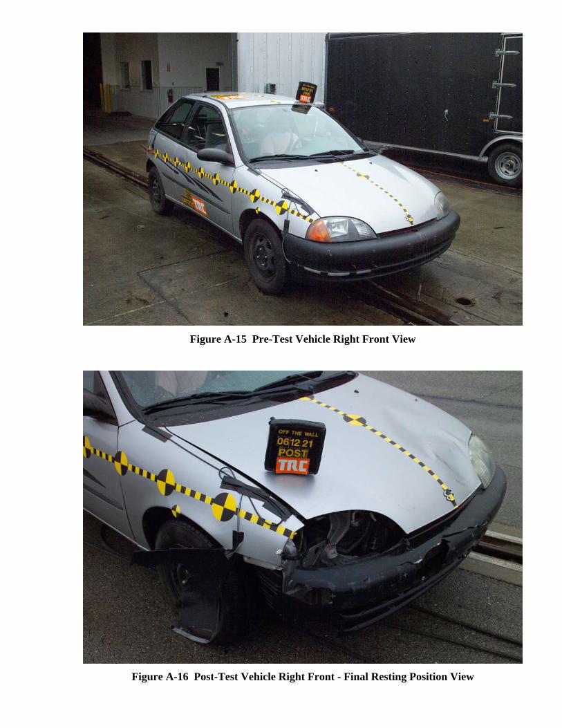
Figure A-15 Pre-Test Vehicle Right Front View
Figure A-16 Post-Test Vehicle Right Front - Final Resting Position View

Figure A-17 Post-Test Vehicle Damage - View 1
Figure A-18 Post-Test Vehicle Damage - View 2

Figure A-19 Pre-Test Front Underbody View
Figure A-20 Post-Test Front Underbody View

Figure A-21 Pre-Test Mid Front Underbody View
Figure A-22 Post-Test Mid Front Underbody View

Figure A-23 Pre-Test Mid Underbody View
Figure A-24 Post-Test Mid Underbody View

Figure A-25 Pre-Test Mid Rear Underbody View
Figure A-26 Post-Test Mid Rear Underbody View

Figure A-27 Pre-Test Rear Underbody View
Figure A-28 Post-Test Rear Underbody View

Figure A-29 Pre-Test Engine Compartment View
Figure A-30 Post-Test Engine Compartment View

Figure A-31 Pre-Test Overhead Impact Alignment View
Figure A-32 Pre-Test Front Impact Alignment View

Figure A-33 Pre-Test Left Front Impact Alignment - View 1
Figure A-34 Pre-Test Left Front Impact Alignment - View 2

Figure A-35 Pre-Test Channelizing Barricade Upstream Overall View
Intentionally Left Blank

Figure A-36 Pre-Test Channelizing Barricade Impact Side Upstream Overall View
Figure A-37 Post-Test Channelizing Barricade Impact Side Upstream Overall View
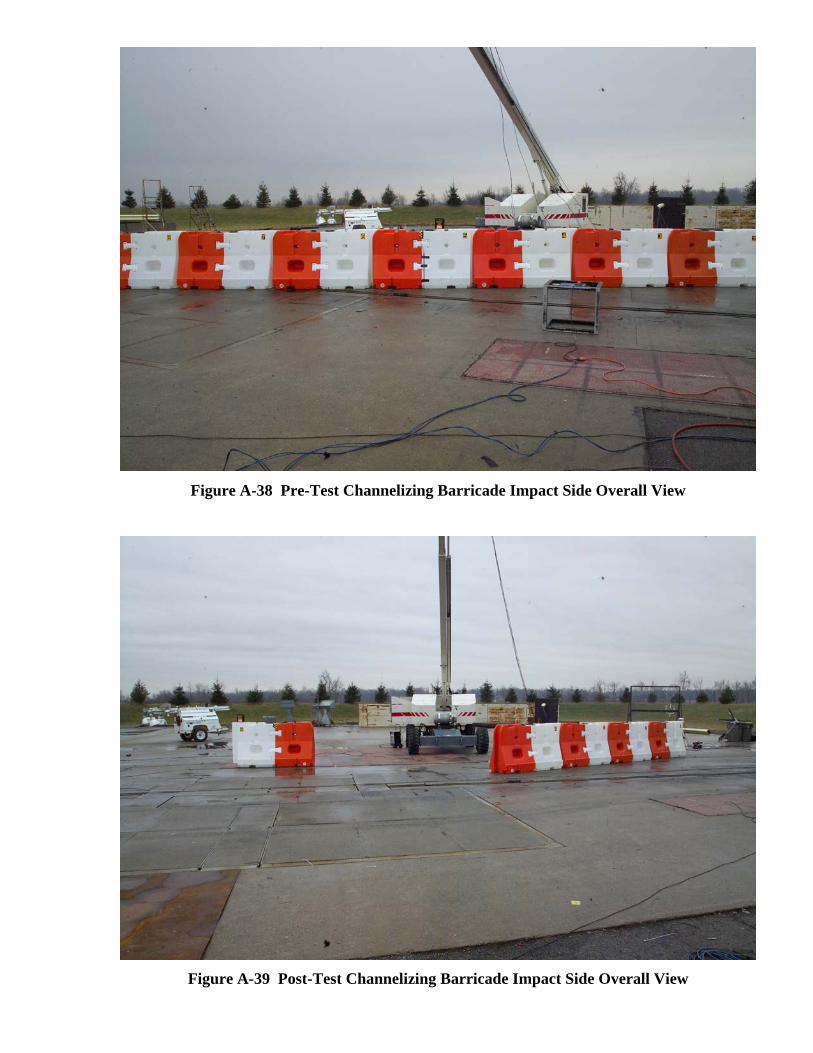
Figure A-38 Pre-Test Channelizing Barricade Impact Side Overall View
Figure A-39 Post-Test Channelizing Barricade Impact Side Overall View

Figure A-40 Pre-Test Channelizing Barricade Impact Side Downstream Overall - View 1
Figure A-41 Post-Test Channelizing Barricade Impact Side Downstream Overall - View 1

Figure A-42 Pre-Test Channelizing Barricade Impact Side Downstream Overall - View 2
Figure A-43 Post-Test Channelizing Barricade Impact Side Downstream Overall - View 2

Figure A-44 Pre-Test Channelizing Barricade Downstream Overall View
Figure A-45 Post-Test Channelizing Barricade Downstream Overall View

Figure A-46 Pre-Test Channelizing Barricade Non-Impact Side Downstream Overall View
Figure A-47 Post-Test Channelizing Barricade Non-Impact Side Downstream Overall View

Figure A-48 Pre-Test Channelizing Barricade Non-Impact Side Overall View
Intentionally Left Blank

Figure A-49 Pre-Test Channelizing Barricade Non-Impact Side Upstream Overall View
Figure A-50 Post-Test Channelizing Barricade Non-Impact Side Upstream Overall View

Figure A-51 Post-Test Barricade 1 View
Figure A-52 Post-Test Barricade 2 View

Figure A-53 Post-Test Barricade 3 View
Figure A-54 Post-Test Barricade 4 View

Figure A-55 Post-Test Barricade 5 View
Figure A-56 Post-Test Barricade 6 View

Figure A-57 Post-Test Barricade 7 View
Figure A-58 Post-Test Barricade 8 View

Figure A-59 Post-Test Barricade 9 View
Figure A-60 Post-Test Barricade 10 View

Figure A-61 Post-Test Damage to Barricade 5 - View 1
Figure A-62 Post-Test Damage to Barricade 5 - View 2

Figure A-63 Post-Test Damage to Barricade 6 - View 1
Figure A-64 Post-Test Damage to Barricade 6 - View 2

Figure A-65 Post-Test Damage to Barricade 8 View
Intentionally Left Blank

Figure A-66 Post-Test Channelizing Barricade Resting Position - View 1
Figure A-67 Post-Test Channelizing Barricade Resting Position - View 2

Figure A-68 Post-Test Channelizing Barricade Resting Position - View 3
Figure A-69 Post-Test Channelizing Barricade Resting Position - View 4

Figure A-70 Post-Test Channelizing Barricade Resting Position - View 5
Figure A-71 Post-Test Channelizing Barricade and Vehicle Resting Positions View
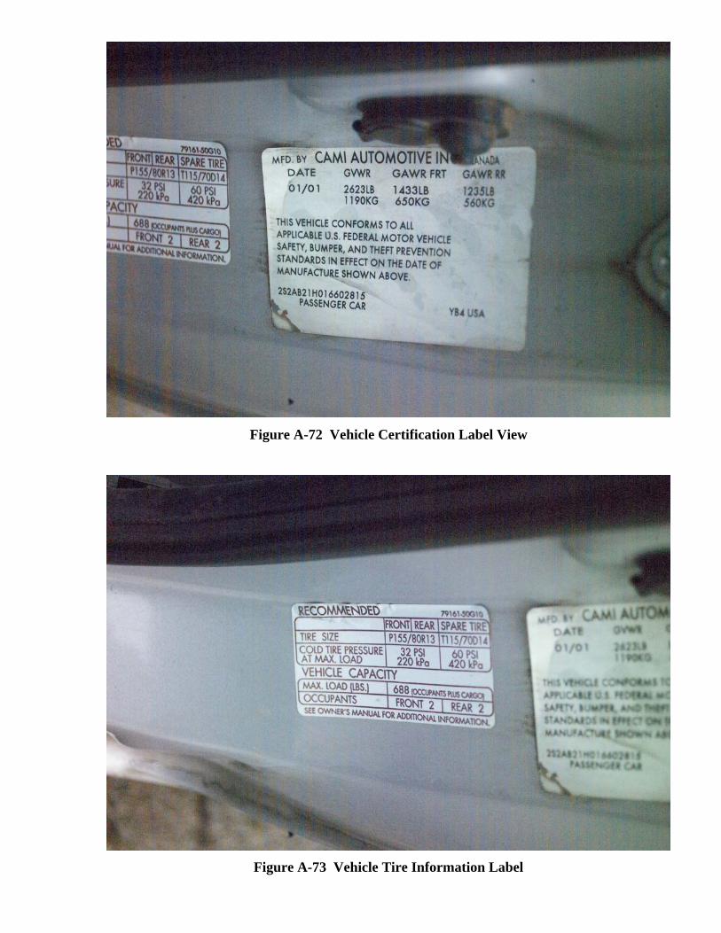
Figure A-72 Vehicle Certification Label View
Figure A-73 Vehicle Tire Information Label

Figure A-74 Post-Test Primary Digital Light Trap Readout View
Figure A-75 Post-Test Secondary Digital Light Trap Readout View

B-1
Appendix B
NCHRP 350 3-71 Test Data Plots

-500 0 500 1000 1500 2000 2500 3000
-12.5
-10
-7.5
-5
-2.5
0
2.5
5
10VEHCCG0000ACXD
Time [ms]Max. Value4.48 g at 840.00 ms
Min. Value-10.35 g at 75.60 ms
NCHRP350 Test 3-71 on Multi-Barrier Model MB-42x72 JSS LCBVehicle CG X-Axis Acceleration
TRC Inc. Test Lab: CTFCustomer: Off the Wall Products, LLCTest Number: 061221
Date: 12/21/2006Time: 11:11
Filter: CFC_60
Acc
ele r
atio
n [ g
]

-500 0 500 1000 1500 2000 2500 3000
12.5
15
17.5
20
22.5
25
27.5
30
10VEHCCG0000VEXC
Time [ms]Max. Value27.92 m/s at 5.00 ms
Min. Value13.62 m/s at 3,000.00 ms
NCHRP350 Test 3-71 on Multi-Barrier Model MB-42x72 JSS LCBVehicle CG X-Axis Velocity
TRC Inc. Test Lab: CTFCustomer: Off the Wall Products, LLCTest Number: 061221
Date: 12/21/2006Time: 11:11
Filter: CFC_180
Vel
ocity
[m/ s
]

-500 0 500 1000 1500 2000 2500 3000
0
10
20
30
40
50
60
10VEHCCG0000DCXC
Time [ms]Max. Value53.07 m at 3,000.00 ms
Min. Value0.00 m at 0.00 ms
NCHRP350 Test 3-71 on Multi-Barrier Model MB-42x72 JSS LCBVehicle CG X-Axis Displacement
TRC Inc. Test Lab: CTFCustomer: Off the Wall Products, LLCTest Number: 061221
Date: 12/21/2006Time: 11:11
Filter: CFC_180
Dis
tanc
e [m
]

-500 0 500 1000 1500 2000 2500 3000
-6
-4
-2
0
2
4
6
10VEHCCG0000ACYD
Time [ms]Max. Value4.80 g at 842.10 ms
Min. Value-5.01 g at 19.30 ms
NCHRP350 Test 3-71 on Multi-Barrier Model MB-42x72 JSS LCBVehicle CG Y-Axis Acceleration
TRC Inc. Test Lab: CTFCustomer: Off the Wall Products, LLCTest Number: 061221
Date: 12/21/2006Time: 11:11
Filter: CFC_60
Acc
ele r
atio
n [ g
]

-500 0 500 1000 1500 2000 2500 3000
-2
-1.5
-1
-0.5
0
0.5
1
1.5
2
10VEHCCG0000VEYC
Time [ms]Max. Value1.57 m/s at 648.30 ms
Min. Value-1.77 m/s at 1,456.50 ms
NCHRP350 Test 3-71 on Multi-Barrier Model MB-42x72 JSS LCBVehicle CG Y-Axis Velocity
TRC Inc. Test Lab: CTFCustomer: Off the Wall Products, LLCTest Number: 061221
Date: 12/21/2006Time: 11:11
Filter: CFC_180
Vel
ocity
[m/ s
]

-500 0 500 1000 1500 2000 2500 3000
-0.75
-0.5
-0.25
0
0.25
0.5
0.75
1
10VEHCCG0000DCYC
Time [ms]Max. Value0.77 m at 1,056.20 ms
Min. Value-0.68 m at 3,000.00 ms
NCHRP350 Test 3-71 on Multi-Barrier Model MB-42x72 JSS LCBVehicle CG Y-Axis Displacement
TRC Inc. Test Lab: CTFCustomer: Off the Wall Products, LLCTest Number: 061221
Date: 12/21/2006Time: 11:11
Filter: CFC_180
Dis
tanc
e [m
]

-500 0 500 1000 1500 2000 2500 3000
-12.5
-10
-7.5
-5
-2.5
0
2.5
5
7.5
10VEHCCG0000ACZD
Time [ms]Max. Value6.96 g at 840.30 ms
Min. Value-11.10 g at 848.20 ms
NCHRP350 Test 3-71 on Multi-Barrier Model MB-42x72 JSS LCBVehicle CG Z-Axis Acceleration
TRC Inc. Test Lab: CTFCustomer: Off the Wall Products, LLCTest Number: 061221
Date: 12/21/2006Time: 11:11
Filter: CFC_60
Acc
ele r
atio
n [ g
]

-500 0 500 1000 1500 2000 2500 3000
0
2.5
5
7.5
10
12.5
15
10VEHCCG0000ACRD
Time [ms]Max. Value13.72 g at 848.30 ms
Min. Value0.04 g at -0.20 ms
NCHRP350 Test 3-71 on Multi-Barrier Model MB-42x72 JSS LCBVehicle CG Resultant Acceleration
TRC Inc. Test Lab: CTFCustomer: Off the Wall Products, LLCTest Number: 061221
Date: 12/21/2006Time: 11:11
Filter: CFC_60
Acc
ele r
atio
n [ g
]

-500 0 500 1000 1500 2000 2500 3000
-12.5
-10
-7.5
-5
-2.5
0
2.5
5
10VEHCCGRD00ACXD
Time [ms]Max. Value4.55 g at 839.90 ms
Min. Value-10.48 g at 75.60 ms
NCHRP350 Test 3-71 on Multi-Barrier Model MB-42x72 JSS LCBVehicle CG X-Axis Acceleration - Redundant
TRC Inc. Test Lab: CTFCustomer: Off the Wall Products, LLCTest Number: 061221
Date: 12/21/2006Time: 11:11
Filter: CFC_60
Acc
ele r
atio
n [ g
]

-500 0 500 1000 1500 2000 2500 3000
12.5
15
17.5
20
22.5
25
27.5
30
10VEHCCGRD00VEXC
Time [ms]Max. Value27.92 m/s at 3.70 ms
Min. Value13.16 m/s at 3,000.00 ms
NCHRP350 Test 3-71 on Multi-Barrier Model MB-42x72 JSS LCBVehicle CG X-Axis Velocity - Redundant
TRC Inc. Test Lab: CTFCustomer: Off the Wall Products, LLCTest Number: 061221
Date: 12/21/2006Time: 11:11
Filter: CFC_180
Vel
ocity
[m/ s
]

-500 0 500 1000 1500 2000 2500 3000
0
10
20
30
40
50
60
10VEHCCGRD00DCXC
Time [ms]Max. Value52.35 m at 3,000.00 ms
Min. Value0.00 m at 0.00 ms
NCHRP350 Test 3-71 on Multi-Barrier Model MB-42x72 JSS LCBVehicle CG X-Axis Displacement - Redundant
TRC Inc. Test Lab: CTFCustomer: Off the Wall Products, LLCTest Number: 061221
Date: 12/21/2006Time: 11:11
Filter: CFC_180
Dis
tanc
e [m
]

-500 0 500 1000 1500 2000 2500 3000
-6
-4
-2
0
2
4
6
10VEHCCGRD00ACYD
Time [ms]Max. Value4.27 g at 842.60 ms
Min. Value-4.71 g at 19.20 ms
NCHRP350 Test 3-71 on Multi-Barrier Model MB-42x72 JSS LCBVehicle CG Y-Axis Acceleration - Redundant
TRC Inc. Test Lab: CTFCustomer: Off the Wall Products, LLCTest Number: 061221
Date: 12/21/2006Time: 11:11
Filter: CFC_60
Acc
ele r
atio
n [ g
]

-500 0 500 1000 1500 2000 2500 3000
-1.5
-1
-0.5
0
0.5
1
1.5
2
10VEHCCGRD00VEYC
Time [ms]Max. Value1.97 m/s at 3,000.00 ms
Min. Value-1.14 m/s at 1,452.50 ms
NCHRP350 Test 3-71 on Multi-Barrier Model MB-42x72 JSS LCBVehicle CG Y-Axis Velocity - Redundant
TRC Inc. Test Lab: CTFCustomer: Off the Wall Products, LLCTest Number: 061221
Date: 12/21/2006Time: 11:11
Filter: CFC_180
Vel
ocity
[m/ s
]

-500 0 500 1000 1500 2000 2500 3000
-0.5
0
0.5
1
1.5
2
2.5
10VEHCCGRD00DCYC
Time [ms]Max. Value2.14 m at 3,000.00 ms
Min. Value-0.03 m at 127.50 ms
NCHRP350 Test 3-71 on Multi-Barrier Model MB-42x72 JSS LCBVehicle CG Y-Axis Displacement - Redundant
TRC Inc. Test Lab: CTFCustomer: Off the Wall Products, LLCTest Number: 061221
Date: 12/21/2006Time: 11:11
Filter: CFC_180
Dis
tanc
e [m
]

-500 0 500 1000 1500 2000 2500 3000
-15
-10
-5
0
5
10
10VEHCCGRD00ACZD
Time [ms]Max. Value7.73 g at 839.80 ms
Min. Value-12.89 g at 848.00 ms
NCHRP350 Test 3-71 on Multi-Barrier Model MB-42x72 JSS LCBVehicle CG Z-Axis Acceleration - Redundant
TRC Inc. Test Lab: CTFCustomer: Off the Wall Products, LLCTest Number: 061221
Date: 12/21/2006Time: 11:11
Filter: CFC_60
Acc
ele r
atio
n [ g
]

-500 0 500 1000 1500 2000 2500 3000
0
2.5
5
7.5
10
12.5
15
17.5
10VEHCCGRD00ACRD
Time [ms]Max. Value15.21 g at 848.10 ms
Min. Value0.02 g at -11.20 ms
NCHRP350 Test 3-71 on Multi-Barrier Model MB-42x72 JSS LCBVehicle CG Resultant Acceleration - Redundant
TRC Inc. Test Lab: CTFCustomer: Off the Wall Products, LLCTest Number: 061221
Date: 12/21/2006Time: 11:11
Filter: CFC_60
Acc
ele r
atio
n [ g
]

-500 0 500 1000 1500 2000 2500 3000
-300
-200
-100
0
100
200
300
400
10VEHCCG0000AVXA
Time [ms]Max. Value331.30 º/s at 812.20 ms
Min. Value-276.97 º/s at 930.50 ms
NCHRP350 Test 3-71 on Multi-Barrier Model MB-42x72 JSS LCBGYRO at CG X
TRC Inc. Test Lab: CTFCustomer: Off the Wall Products, LLCTest Number: 061221
Date: 12/21/2006Time: 11:11
Filter: CFC_1000
Ang
ular
Ve l
ocity
[º/ s
]

-500 0 500 1000 1500 2000 2500 3000
-300
-200
-100
0
100
200
300
10VEHCCG0000AVYA
Time [ms]Max. Value287.56 º/s at 852.50 ms
Min. Value-232.71 º/s at 33.60 ms
NCHRP350 Test 3-71 on Multi-Barrier Model MB-42x72 JSS LCBGYRO at CG Y
TRC Inc. Test Lab: CTFCustomer: Off the Wall Products, LLCTest Number: 061221
Date: 12/21/2006Time: 11:11
Filter: CFC_1000
Ang
ular
Ve l
ocity
[º/ s
]

-500 0 500 1000 1500 2000 2500 3000
-150
-100
-50
0
50
100
150
200
10VEHCCG0000AVZA
Time [ms]Max. Value176.22 º/s at 125.10 ms
Min. Value-147.03 º/s at 29.20 ms
NCHRP350 Test 3-71 on Multi-Barrier Model MB-42x72 JSS LCBGYRO at CG Z
TRC Inc. Test Lab: CTFCustomer: Off the Wall Products, LLCTest Number: 061221
Date: 12/21/2006Time: 11:11
Filter: CFC_1000
Ang
ular
Ve l
ocity
[º/ s
]

0 1000 2000 3000 4000 5000 60000
0.1
0.2
0.3
0.4
0.5
NCHRP350 Test 3-71 on Multi-Barrier Model MB-42x72 JSS LCBNCHRP350 Analysis
TRC Inc. Test Lab: CTFCustomer: Off the Wall Products, LLCTest Number: 061221
Date: 12/21/2006Time: 11:11
Theoretical Head Impact VelocityChannels
10VEHCCG0000AVZC10VEHCCG0000ACXC10VEHCCG0000ACYC
Initial Yaw Angle: 0 radiansDistance of Head CG to Vehc. CG: 0 m
Distance of Head to Impact Surface (X): 0.6 mDistance of Head to Impact Surface (Y): 0.3 m
Time of Flight: 193.90 msHead Impact Velocity: 24.38 km/h
Post-Impact Head DecelerationChannels
10VEHCCG0000ACXC10VEHCCG0000ACYC
Time of Collision: 0.1939 s
Time of Maximum Head Delay: 842.70 msMaximum Head Deceleration After Impact: 5.59 g
Occupant Impact VelocityChannels
10VEHCCG0000ACXC10VEHCCG0000ACYC
Distance of Head CG to Vehc. CG: 0 mDistance of Head to Impact Surface (X): 0.6 mDistance of Head to Impact Surface (Y): 0.3 m
Time of Flight: 193.70 msOccupant Impact Velocity: 24.25 km/h (X)Occupant Impact Velocity: -1.33 km/h (Y)
Occupant Ridedown AccelerationChannels
10VEHCCG0000ACXC10VEHCCG0000ACYC
Time of Collision: 0.1937 s
Time of the Stoppage Deceleration (X): 842.70 msStoppage Deceleration After the Impact (X): 5.57 gTime of the Stoppage Deceleration (Y): 837.30 msStoppage Deceleration After the Impact (Y): 2.97 g
Channels10VEHCCG0000ACXC10VEHCCG0000ACYC10VEHCCG0000ACZC
Time Interval: 50 msASI Maximum
0.48 at 71.00 ms50ms Moving Average
x-direction = -5.7 g at 96.3 msy-direction = 1.4 g at 138.1 msz-direction = -2.4 g at 844.5 ms
Time [ms]
Acceleration Severity Index

C-1
Appendix C
Miscellaneous Test Data

820C Passenger Vehicle Accelerometer Placement
Side View
Bottom View
1 2
1 2
X
Z(Z) + Vertical
(X) + Longitudinal
Y
X(X) + Longitudinal
(Y) + Lateral
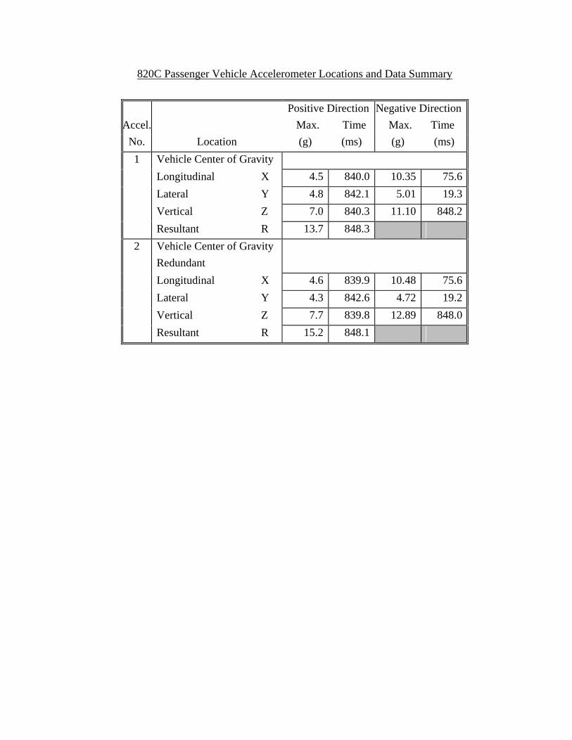
820C Passenger Vehicle Accelerometer Locations and Data Summary
Accel.
Positive Direction Max. Time
Negative Direction Max. Time
No. Location (g) (ms) (g) (ms) 1 Vehicle Center of Gravity Longitudinal X 4.5 840.0 10.35 75.6 Lateral Y 4.8 842.1 5.01 19.3 Vertical Z 7.0 840.3 11.10 848.2 Resultant R 13.7 848.3
2 Vehicle Center of Gravity Redundant
Longitudinal X 4.6 839.9 10.48 75.6 Lateral Y 4.3 842.6 4.72 19.2 Vertical Z 7.7 839.8 12.89 848.0 Resultant R 15.2 848.1

Post-Test Barrier Diagram
Directionof Travel
Impact Point

Impacting Vehicle Crush Data
NOTES: L is pre-test length of contact surface. C1 through C6 are spaced equally apart. CL is vehicle centerline. Vehicle: 2001 Suzuki Swift 2-door
Pre-test Post-test Crush L 1423 mm N/A N/A C1 3875 mm 3624 mm 251 mm C2 3990 mm 3731 mm 259 mm C3 4045 mm 3777 mm 268 mm C4 4045 mm 3765 mm 280 mm C5 3994 mm 3725 mm 269 mm C6 3878 mm 3610 mm 268 mm CL 4050 mm 3780 mm 270 mm

Impacting Vehicle Occupant Compartment Deformation
Test No. 061221
Measurement
Pre-Test
Post-Test
Difference
Percent Reduction
AL: Left Dash to Rear 1755 mm 1755 mm 0 mm 0.0% AR: Right Dash to Rear 1718 mm 1718 mm 0 mm 0.0% BL: Left Roof to Floor 1030 mm 1030 mm 0 mm 0.0% BR: Right Roof to Floor 1030 mm 1030 mm 0 mm 0.0% CL: Left Toeboard to Rear 2095 mm 2095 mm 0 mm 0.0% CR: Right Toeboard to Rear 2073 mm 2073 mm 0 mm 0.0% DL: Left Lower Dash to Floor 345 mm 345 mm 0 mm 0.0% DR: Right Lower Dash to Floor
310 mm 310 mm 0 mm 0.0%
E: Interior Width 1250 mm 1250 mm 0 mm 0.0% F: Right Window Lower Edge to Left Window Upper Edge
1250 mm 1250 mm 0 mm 0.0%
G: Left Window Lower Edge to Right Window Upper Edge
1270 mm 1270 mm 0 mm 0.0%

Camera Positions

Camera Information
Camera Lens Speed Purpose of Number Location Type (mm) (fps) Camera Data
1 Real-time panning Canon Zoom 30 Documentation
2 Overhead wide Redlake-LE 12.5 500 Vehicle dynamics
3 Overhead tight Redlake-LE 25 500 Impact alignment
4 Left wide Redlake-LE 12.5 500 Vehicle dynamics
5 Left wide upstream Redlake-LE 6.5 500 Vehicle dynamics
6 Left tight Redlake-LE 25 500 Impact alignment
7 Right oblique Redlake-LE 12.5 500 Vehicle dynamics
8 Left oblique Redlake-LE 12.5 500 Vehicle dynamics


D-1
Appendix D
Multi-Barrier Model MB-42x72 JSS LCB Channelizing Barricade System Specifications
Additional test article information to be supplied by Off The Wall Products, LLC