ndia armaments forum 2017 development of accurate finite ... · development of accurate finite...
TRANSCRIPT

GUN & ELECTRIC WEAPON SYSTEMS DEPARTMENT (E)
NAVAL SURFACE WARFARE CENTER · DAHLGREN DIVISION
NSWCDD-PN-17-00173; Distribution A. Approved for Public Release.
NDIA Armaments Forum 2017 Development of Accurate Finite Element Models and Testing Procedures for Bolted Joints in Large Caliber Gun Weapon Systems
Presented by: Greg Fish Ryan Braughler Michael Koehler

GUN & ELECTRIC WEAPON SYSTEMS DEPARTMENT
Purpose
• This briefing addresses the challenges presented to the analyst in the modeling of bolted joints to ensure the interaction between the gun weapon system and platform meets the requirements of the interface control document.
• Agenda: • Development Lifecycle in E34 • An overview of the mechanics of a bolted joint • Small Scale Testing • Traditional Finite Element Analysis
Distribution A
GUN & ELECTRIC WEAPON SYSTEMS DEPARTMENT
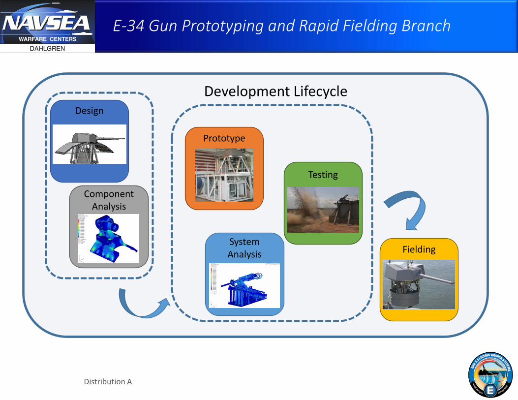
E-34 Gun Prototyping and Rapid Fielding Branch
Fielding
Testing
Component Analysis
System Analysis
Design
Prototype
Development Lifecycle
Distribution A

GUN & ELECTRIC WEAPON SYSTEMS DEPARTMENT
Analysis and Special Projects Group
Component Analysis & Optimization
System Analysis Testing Model Validation
Instrumentation and Data Acquisition
Design Realization/Validation
Distribution A

GUN & ELECTRIC WEAPON SYSTEMS DEPARTMENT
System Validation
• Large scale system models have been developed to validate the design and to ensure that requirements are met
• Systems are tested to ensure key performance parameters are met
• Test yields data which is used to validate the analytical models
• Test/Model discrepancies
Distribution A

GUN & ELECTRIC WEAPON SYSTEMS DEPARTMENT
How Bolted Joints Behave
Load Cell
• Developed by Joseph Shigley • Joint and bolts act like
springs • Joint is modeled as a soft
bolt spring in parallel with a stiff member joint
• Stress distribution modeled as frustum of a cone
Distribution A
GUN & ELECTRIC WEAPON SYSTEMS DEPARTMENT
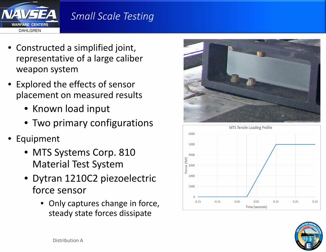
Small Scale Testing
• Constructed a simplified joint, representative of a large caliber weapon system
• Explored the effects of sensor placement on measured results
• Known load input • Two primary configurations
• Equipment • MTS Systems Corp. 810
Material Test System • Dytran 1210C2 piezoelectric
force sensor • Only captures change in force,
steady state forces dissipate
Distribution A

GUN & ELECTRIC WEAPON SYSTEMS DEPARTMENT
Small Scale Testing
Test Case A • Force sensor sandwiched
between fixtures, with a machined washer
• Typical setup for a ring style force sensor
• May not be possible to install in this configuration
• Alignment critical designs • Interface concerns
Distribution A
GUN & ELECTRIC WEAPON SYSTEMS DEPARTMENT
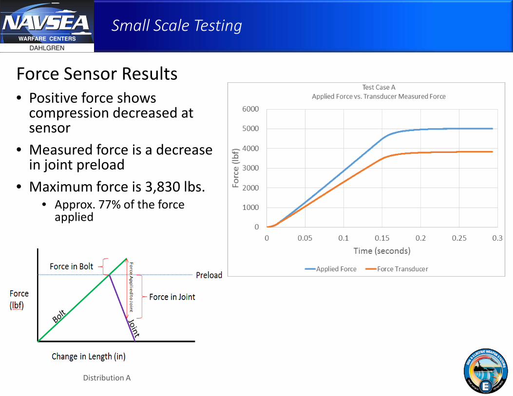
Small Scale Testing
Force Sensor Results • Positive force shows
compression decreased at sensor
• Measured force is a decrease in joint preload
• Maximum force is 3,830 lbs. • Approx. 77% of the force
applied
Distribution A

GUN & ELECTRIC WEAPON SYSTEMS DEPARTMENT
Small Scale Testing
Test Case B • Less typical usage of force
sensor • Changed where the sensor is in
the load path • Necessary if the height of the
joint cannot be changed without impacting the overall performance
Distribution A

GUN & ELECTRIC WEAPON SYSTEMS DEPARTMENT
Small Scale Testing
Force Sensor Results • Negative force shows
compression increased at the sensor
• Measured force is an increase in bolt load
• Maximum force is 310 lbs. • Approx. 6% of force applied
Distribution A

GUN & ELECTRIC WEAPON SYSTEMS DEPARTMENT
Small Scale Testing Summary
• Observer Effect • Joint behavior is changed because of the added force sensor and
change in bolt length • Test Case A + Test Case B do not equal applied force
• Moving the sensor further changed the joint behavior
• Force sensors are not plug and play • Hard to gather meaningful data using a force sensor out of the box
• Small scale testing is important • Needed to correctly interpret results from a large scale test • Can also be used to calibrate the sensors for the specific joint
• Other methods of modeling the joint may be more efficient than numerous physical tests
Distribution A
GUN & ELECTRIC WEAPON SYSTEMS DEPARTMENT
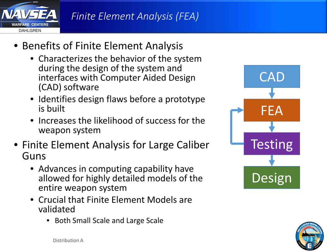
Finite Element Analysis (FEA)
• Benefits of Finite Element Analysis • Characterizes the behavior of the system
during the design of the system and interfaces with Computer Aided Design (CAD) software
• Identifies design flaws before a prototype is built
• Increases the likelihood of success for the weapon system
• Finite Element Analysis for Large Caliber Guns
• Advances in computing capability have allowed for highly detailed models of the entire weapon system
• Crucial that Finite Element Models are validated
• Both Small Scale and Large Scale
CAD
FEA
Testing
Design
Distribution A

GUN & ELECTRIC WEAPON SYSTEMS DEPARTMENT
Finite Element Analysis
• Finite Element Model (FEM) • Finite Element Model was developed
to be identical to the small scale test • The load applied to the specimen was
the same as the test, 5000 lbf. ramped over 25ms
• Data was collected for: • Load cell force • Bolt Load • Force between every surface
• LS-DYNA was used for the finite element analysis using implicit time integration
5000 lbf
5000 lbf
Distribution A
GUN & ELECTRIC WEAPON SYSTEMS DEPARTMENT
Finite Element Analysis
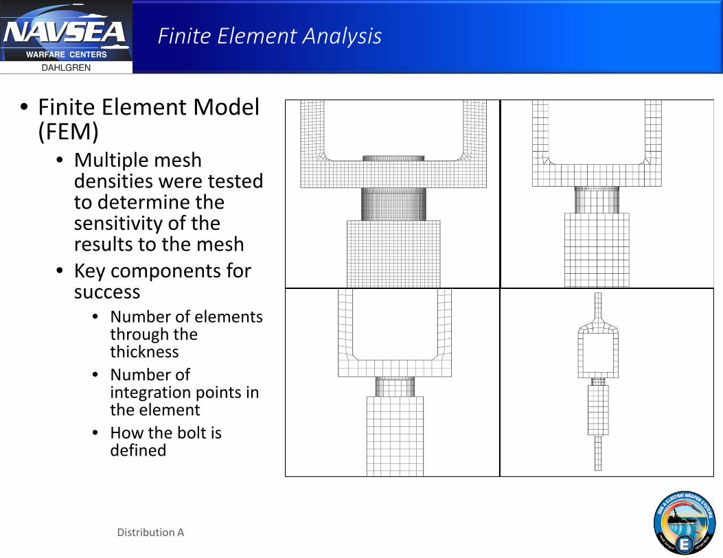
• Finite Element Model (FEM)
• Multiple mesh densities were tested to determine the sensitivity of the results to the mesh
• Key components for success
• Number of elements through the thickness
• Number of integration points in the element
• How the bolt is defined
Distribution A
GUN & ELECTRIC WEAPON SYSTEMS DEPARTMENT
Finite Element Analysis
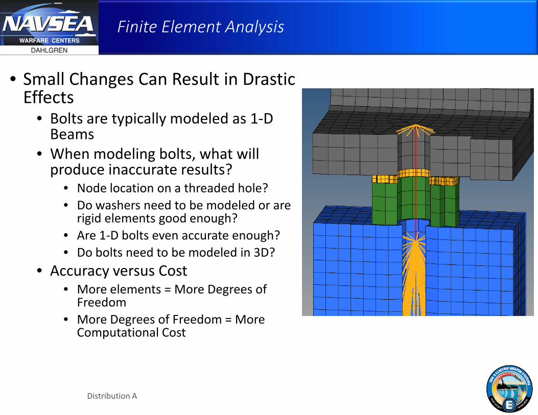
• Small Changes Can Result in Drastic Effects
• Bolts are typically modeled as 1-D Beams
• When modeling bolts, what will produce inaccurate results?
• Node location on a threaded hole? • Do washers need to be modeled or are
rigid elements good enough? • Are 1-D bolts even accurate enough? • Do bolts need to be modeled in 3D?
• Accuracy versus Cost • More elements = More Degrees of
Freedom • More Degrees of Freedom = More
Computational Cost
Distribution A

GUN & ELECTRIC WEAPON SYSTEMS DEPARTMENT
Finite Element Analysis Results
• Mesh Density • At least 2 elements
through the thickness • Fully integrated
elements • Underintegrated
elements are troublesome in a course mesh, as expected
• Modeling 1-D Bolts • Thin washers can be
replaced with rigid elements
• Accurate bolt length is imperative
• Threaded hole = ½ diameter
Distribution A

GUN & ELECTRIC WEAPON SYSTEMS DEPARTMENT
Conclusions
• Theoretical calculations are often over simplified and not capable of predicting joint loads accurately
• Joint loads can be easily underestimated during physical testing
• Instrumentation can change the joint behavior and often measures only part of the reaction load
• Can be overcome by calibrating the instrumentation for a specific joint, usually through small scale testing
• Finite Element Analysis can easily measure the entire reaction load
• Finite Element Models are sensitive to a number of variables • Fine mesh densities and accurate bolt lengths greatly improve results
• Finite Element Models should be validated • Comparing analytical models to controlled physical testing is a great way to
prove accuracy
Distribution A