network processors and web servers cs 213 lecture 17 from: ibm technical report
Post on 22-Dec-2015
214 views
TRANSCRIPT
Network Processors and Web Servers
CS 213
LECTURE 17From: IBM Technical Report
Intel® IXP2XXX Network Processor Architecture and
Programming
Prof. Laxmi Bhuyan
Computer Science UC Riverside
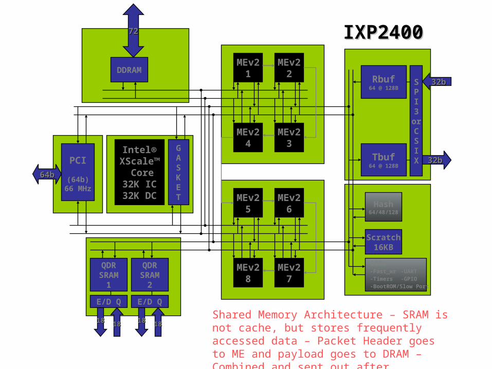
MEv26
MEv27
MEv25
MEv28
Intel®XScale™
Core32K IC32K DC
Rbuf64 @ 128B
Tbuf64 @ 128B
Hash64/48/128
Scratch16KB
QDRSRAM
1
QDRSRAM
2
DDRAM
GASKET
PCI
(64b)66 MHz
32b32b
32b32b
1818 18181818 1818
7272
64b64b
SPI3orCSIX
E/D Q E/D Q
MEv22
MEv23
MEv21
MEv24
CSRs -Fast_wr -UART-Timers -GPIO-BootROM/Slow Port
IXP2400IXP2400
Shared Memory Architecture – SRAM is not cache, but stores frequently accessed data – Packet Header goes to ME and payload goes to DRAM – Combined and sent out after processing

SSDDRRAAMM
IXP2400 Full-Duplex OC-48 System Implementation
IXF6048Framer
IXP2400Ingress Processor
IXP2400Egress Processor
SwitchFabricGasket
SSDDRRAAMM
QQDDRR
QQDDRR
DDR SDRAM Packet Memory
QDR SRAM Queues &
Tables
DDR SDRAM Packet Memory
QDR SRAM Queues &
Tables
1x OC-48 or4x OC-12
OC-48 OC48
OC48OC48
QQDDRR
QQDDRR
TTCCAAMM
ClassificationAccelerator
TTCCAAMM
ClassificationAccelerator
Host CPU(IOP or iA) SAR’ing
ClassificationMeteringPolicingInitial Congestion Management
Ingress Processor
Traffic Shaping Flexible Choices diff serve TM 4.0 …
Egress Processor
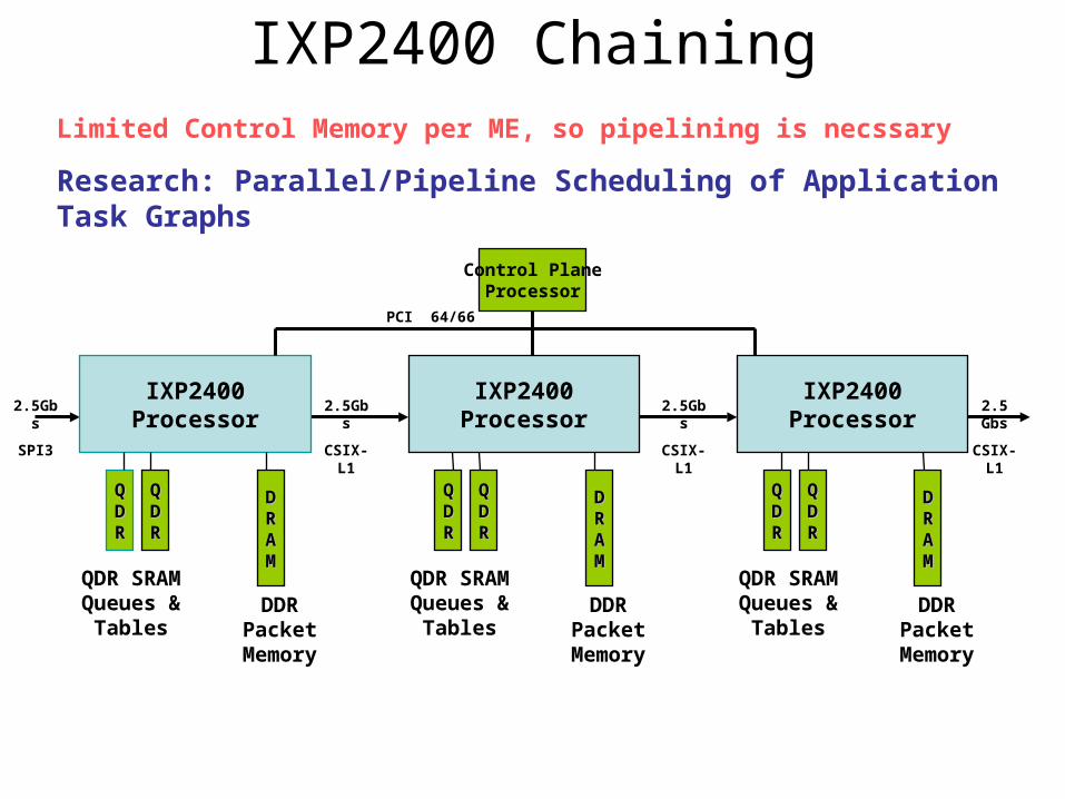
IXP2400 Chaining
PCI 64/66
2.5Gbs
CSIX-L1
IXP2400Processor
DDRPacket Memory
IXP2400Processor
QDR SRAM Queues & Tables
DDRRAAMM
QQDDRR
QQDDRR
QDR SRAM Queues & Tables
DDRRAAMM
QQDDRR
QQDDRR
DDRPacket Memory
2.5 Gbs
CSIX-L1
IXP2400Processor
QDR SRAM Queues & Tables
DDRRAAMM
QQDDRR
QQDDRR
DDRPacket Memory
Control PlaneProcessor
2.5Gbs
CSIX-L1
2.5Gbs
SPI3
Limited Control Memory per ME, so pipelining is necssary
Research: Parallel/Pipeline Scheduling of Application Task Graphs

Intel®XScale™
Core32K IC32K DC MEv2
10MEv2
11MEv2
12
MEv215
MEv214
MEv213
Rbuf64 @ 128B
Tbuf64 @ 128B
Hash48/64/128
Scratch16KBQDR
SRAM2
QDRSRAM
1
RDRAM1
RDRAM3
RDRAM2
GASKET
PCI
(64b)66 MHz
IXP2800IXP2800
16b16b
16b16b
1818 18181818 1818
1818 1818 1818
64b64b
SPI4orCSIX
Stripe
E/D Q E/D Q
QDRSRAM
3
E/D Q
1818 1818
MEv29
MEv216
MEv22
MEv23
MEv24
MEv27
MEv26
MEv25
MEv21
MEv28
CSRs -Fast_wr -UART-Timers -GPIO-BootROM/SlowPort
QDRSRAM
4
E/D Q
1818 1818

IXP2800 and IXP2400 Comparison
Dual chip full duplex OC48Dual chip full duplex OC192Performance
8 (MEv2)16 (MEv2)Number of MicroEngines
Separate 32 bit Tx & Rx configurable to SPI-3, UTOPIA 3
or CSIX_L1
Separate 16 bit Tx & Rx configurable to SPI-4 P2 or
CSIX_L1
Media Interface
2 channels QDR (or co-processor)
4 channels QDR (or co-processor)
SRAM Memory
1 channel DDR DRAM - 150MHz; Up to 2GB
3 channels RDRAM 800/1066MHz; Up to 2GB
DRAM Memory
600/400MHz1.4/1.0 GHz/ 650 MHzFrequency
IXP2400IXP2800
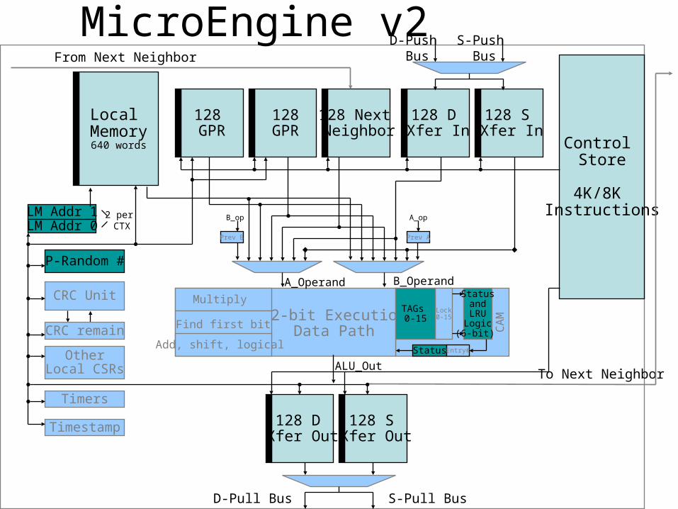
128GPR
Control Store
4K/8K Instructions
128 GPR
Local Memory640 words
128 Next Neighbor
128 S Xfer Out
128 D Xfer Out
OtherLocal CSRs
CRC Unit
128 S Xfer In
128 D Xfer In
LM Addr 1LM Addr 0
D-Push Bus
S-Push Bus
D-Pull Bus S-Pull Bus
To Next Neighbor
From Next Neighbor
A_Operand B_Operand
ALU_Out
P-Random #
32-bit ExecutionData Path
Multiply
Find first bit
Add, shift, logical
2 per CTX
CRC remain
Lock0-15
StatusandLRULogic(6-bit)
TAGs 0-15
Status Entry#
CA
M
Timers
Timestamp
Prev B
B_op
Prev A
A_op
MicroEngine v2

Microengine v2 Features – Part 1• Clock Rates
– IXP2400 – 600/400 MHz– IXP2800 - 1.4/1.0 GHz/ 650 MHz
• Control Store– IXP2400 – 4K Instruction store– IXP2800 – 8K Instruction store
• Configurable to 4 or 8 threads– Each thread has its own program counter, registers, signal and wakeup
events– Generalized Thread Signaling (15 signals per thread)
• Local Storage Options– 256 GPRs– 256 Transfer Registers– 128 Next Neighbor Registers– 640 - 32bit words of local memory
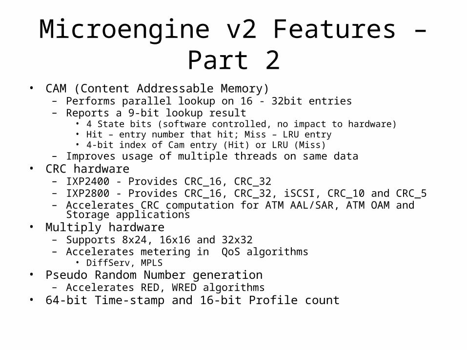
Microengine v2 Features – Part 2
• CAM (Content Addressable Memory)– Performs parallel lookup on 16 - 32bit entries– Reports a 9-bit lookup result
• 4 State bits (software controlled, no impact to hardware)• Hit – entry number that hit; Miss – LRU entry• 4-bit index of Cam entry (Hit) or LRU (Miss)
– Improves usage of multiple threads on same data• CRC hardware
– IXP2400 - Provides CRC_16, CRC_32– IXP2800 - Provides CRC_16, CRC_32, iSCSI, CRC_10 and CRC_5– Accelerates CRC computation for ATM AAL/SAR, ATM OAM and Storage
applications• Multiply hardware
– Supports 8x24, 16x16 and 32x32 – Accelerates metering in QoS algorithms
• DiffServ, MPLS• Pseudo Random Number generation
– Accelerates RED, WRED algorithms• 64-bit Time-stamp and 16-bit Profile count

Intel® XScale™ Core Overview
• High-performance, Low-power, 32-bit Embedded RISC processor
• Clock rate– IXP2400 600 MHz– IXP2800 700/500/325 MHz
• 32 Kbyte instruction cache• 32 Kbyte data cache• 2 Kbyte mini-data cache• Write buffer• Memory management unit

Web Server Architecture

Dispatching AlgorithmsStrategies to select the target server of the web
clusters• Static: Fastest solution to prevent web server
bottleneck, but do not consider the current state of the servers
• Dynamic: Outperform static algorithms by using intelligent decisions, but collecting state information and analyzing them cause expensive overheads
Requirements: (1) Low computational complexity (2) Full compatibility with web standards (3) state information must be readily available without much overhead


Cluster based Architecture Needs a Web Switch

Distributed Architecture

Two ApproachesDepends on which OSI protocol layer at which the web
switch routes inbound packets
• layer-4 switch – Determines the target server when TCP SYN packet is received. Also called content-blind routing because the server selection policy is not based on http contents at the application level
• layer-7 switch (Web Switch) – The switch first establishes a complete TCP connection with the client, examines http request at the application level and then selects a server. Can support sophisticated dispatching policies, but large latency for moving to application level – Also called Content-aware switches or Layer 5 switches in TCP/IP protocol.

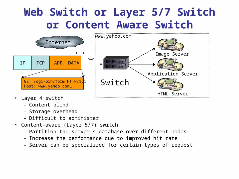
Web Switch or Layer 5/7 Switch or Content Aware Switch
• Layer 4 switch– Content blind– Storage overhead– Difficult to administer
• Content-aware (Layer 5/7) switch– Partition the server’s database over different nodes– Increase the performance due to improved hit rate– Server can be specialized for certain types of request
Switch
Image Server
Application Server
HTML Server
www.yahoo.comInternet
GET /cgi-bin/form HTTP/1.1 Host: www.yahoo.com…
APP. DATATCPIP
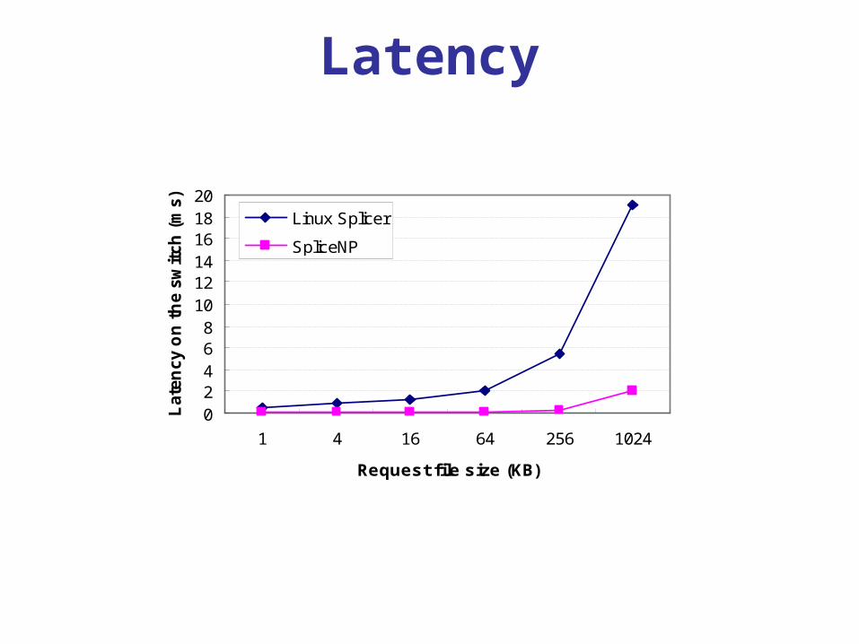
Latency
02468
101214161820
1 4 16 64 256 1024
Request file size (KB)
Late
ncy o
n t
he s
wit
ch
(m
s)
Linux Splicer
SpliceNP

Throughput
0
100
200
300
400
500
600
700
800
1 4 16 64 256 1024
Request file size (KB)
Th
rou
gh
pu
t (M
bp
s) Linux Splicer
SpliceNP