neutral gas dynamics in fireballs - ucla · neutral gas dynamics in fireballs r. l. stenzel,1,a) c....
TRANSCRIPT

Neutral gas dynamics in fireballs
R. L. Stenzel,1,a) C. Ionita,2 and R. Schrittwieser21Department of Physics and Astronomy, University of California, Los Angeles, California 90095-1547, USA2University of Innsbruck, Department for Ion Physics and Applied Physics, A-6020 Innsbruck, Austria
(Received 24 March 2011; accepted 23 April 2011; published online 6 June 2011)
Fireballs are local discharge phenomena on positively biased electrodes in partially ionized
plasmas. Electrons, energized at a double layer, heat neutral gas which expands. The gas pressure
exceeds the plasma pressure, hence becomes important to the stability and transport in fireballs.
The flow of gas moves the electrode and sensors similar to a mica pendulum. Flow speed and
directions are measured. A fireball gun has been developed to partially collimate the flow of hot
gas and heat objects in its path. New applications of fireballs are suggested. VC 2011 AmericanInstitute of Physics. [doi:10.1063/1.3594744]
I. INTRODUCTION
The coupling between charged particles and neutral gas
is of general interest in partially ionized gases. This topic
applies to many fields of plasma physics such as space plas-
mas (ionosphere,1 photosphere,2 comets,3 star formation4),
fusion plasmas (pellet injections,5 divertors6), laser-produced
plasmas,7 processing plasmas (helicons,8,9 capillary dis-
charges10), and even dusty plasmas.11 In high temperature
plasmas, burnout of neutrals is of primary interest. In low
temperature plasmas, the coupling of ion and neutral flows is
of main interest. Localized plasmas, which produce tempera-
ture gradients, lead to pressure gradients and gas flows. One
example of a localized plasma is a fireball or anode dis-
charge.12–18 Little has been reported about neutral gas prop-
erties in and surrounding fireballs. Nevertheless, the transfer
of momentum and energy from the charged particles to the
neutrals is an important topic in the physics of fireballs.
The present paper describes measurements of gas flows
created by pulsed fireballs. The paper describes first the ex-
perimental setup and diagnostics. The section on experimen-
tal results describes various properties of gas flows. A
conclusion summarizes the new findings and suggests possi-
ble applications and further investigations.
II. EXPERIMENT AND PARAMETERS
The experiments were started in the Innsbruck single-
plasma machine19 and followed up in a similar device at
UCLA. These are simple dc discharge plasmas between a fil-
amentary cathode and a grounded chamber wall as anode, as
schematically shown in Fig. 1(a). The plasma of density and
temperature indicated in Fig. 1(a) may be immersed into a
uniform axial field B0 < 40 G. Plasma diagnostics are per-
formed with Langmuir probes.
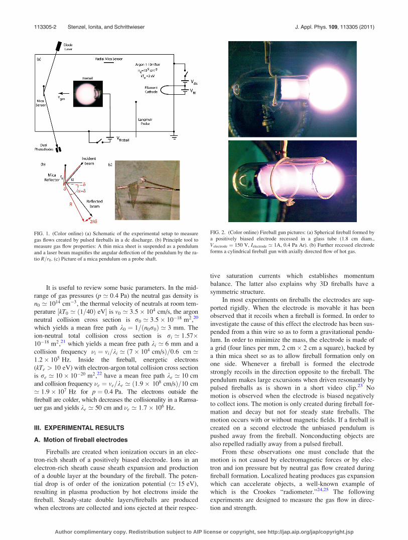
Gas flows are measured with mechanical sensors as
shown in Figs. 1(a)–1(c). The sensor consists of a thin trans-
parent mica sheet (1.5 cm� 1:5 cm� 0:05 mm) suspended
with two wires to form a pendulum. Gas flows cause small
angular deflections which are magnified and detected by
reflecting a laser beam from the mica surface. If the mica
sheet rotates by an angle d, the laser beam is deflected by a
distance 2Rd, where R ¼ 45 cm is the distance from the
mica sensor to the point of projection. The magnification is
2R=r0 ’ 60, where r0 ¼ 1:5 cm is the radius from the axis
of rotation to the laser reflection point. The laser beam is
detected with two identical photodiodes spaced by
Dx ¼ 6 mm apart in the direction of deflection. The light
spot usually swings over both diodes. By recording the two
diode signals on a dual channel oscilloscope one obtains
both the direction and speed of motion of the laser light spot
at the diodes and thereby the speed of the mica sensor. The
diode pair is also movable so as to obtain a time-of-flight
diagram of the laser spot. Two similar mica sensors were
employed, one for measuring the flow in axial direction, a
second one for measuring flows in radial direction. An actual
picture of a mica sensor is shown in Fig. 1(c). The mica sheet
has two holes through which a horizontal fiber glass string
passes which in turn is supported by a forklike probe. The
laser spot hits the bottom of the mica sheet. The actually
used mica sheets were of rectangular shape. Further
improvements included a thin wire for support which had
less friction than a fiber glass thread. Further properties of
the sensors will be discussed below.
Fireballs are created by biasing a electrodes positively
in argon at pressures 0:13 < p < 1:3 Pa (1–10 mTorr). A
new fireball electrode has been developed, consisting of a
circular electrode (1.8 cm diam), recessed up to 4 cm in a
glass cylinder closed at one end, so as to form a plasma gun
with directional gas flow properties, as shown in Fig. 2. A
spherical fireball may form at the open end of the gun with
diameter controlled by electrode voltage and gas pressure.
Gas flows are created by switching stable fireballs on and off
with an externally pulsed voltage. The electrode voltage/cur-
rent (typically 150 V, 1 A, ton > 10 ms, trep > 1 s) is
switched with a pnp transistor in the presence of dc discharge
(typically 100 V, 0:5 A) with electron density ne ’ 109 cm�3,
temperature kTe ’ 2 eV ’ 10 kTi. A digital camera is also
used to take time-averaged images of fireballs.a)Electronic mail: [email protected].
0021-8979/2011/109(11)/113305/8/$30.00 VC 2011 American Institute of Physics109, 113305-1
JOURNAL OF APPLIED PHYSICS 109, 113305 (2011)
Author complimentary copy. Redistribution subject to AIP license or copyright, see http://jap.aip.org/jap/copyright.jsp
It is useful to review some basic parameters. In the mid-
range of gas pressures (p ’ 0:4 Pa) the neutral gas density is
n0 ’ 1014 cm�3, the thermal velocity of neutrals at room tem-
perature ½kT0 ’ ð1=40Þ eV� is v0 ’ 3:5� 104 cm/s, the argon
neutral collision cross section is r0 ’ 3:5� 10�18 m2,20
which yields a mean free path k0 ¼ 1=ðn0r0Þ ’ 3 mm. The
ion-neutral total collision cross section is ri ’ 1:57�10�18 m2,21 which yields a mean free path ki ’ 6 mm and a
collision frequency �i ¼ vi=ki ’ ð7� 104 cm/sÞ=0:6 cm ’1:2� 105 Hz. Inside the fireball, energetic electrons
(kTe > 10 eV) with electron-argon total collision cross section
is re ’ 10� 10�20 m2,22 have a mean free path ke ’ 10 cm
and collision frequency �e ¼ ve=ke ’ ð1:9� 108 cm/sÞ=10 cm
’ 1:9� 107 Hz for p ¼ 0:4 Pa. The electrons outside the
fireball are colder, which decreases the collisionality in a Ramsa-
uer gas and yields ke ’ 50 cm and �e ’ 1:7� 106 Hz.
III. EXPERIMENTAL RESULTS
A. Motion of fireball electrodes
Fireballs are created when ionization occurs in an elec-
tron-rich sheath of a positively biased electrode. Ions in an
electron-rich sheath cause sheath expansion and production
of a double layer at the boundary of the fireball. The poten-
tial drop is of order of the ionization potential (’ 15 eV),
resulting in plasma production by hot electrons inside the
fireball. Steady-state double layers/fireballs are produced
when electrons are collected and ions ejected at their respec-
tive saturation currents which establishes momentum
balance. The latter also explains why 3D fireballs have a
symmetric structure.
In most experiments on fireballs the electrodes are sup-
ported rigidly. When the electrode is movable it has been
observed that it recoils when a fireball is formed. In order to
investigate the cause of this effect the electrode has been sus-
pended from a thin wire so as to form a gravitational pendu-
lum. In order to minimize the mass, the electrode is made of
a grid (four lines per mm, 2 cm� 2 cm a square), backed by
a thin mica sheet so as to allow fireball formation only on
one side. Whenever a fireball is formed the electrode
strongly recoils in the direction opposite to the fireball. The
pendulum makes large excursions when driven resonantly by
pulsed fireballs as is shown in a short video clip.23 No
motion is observed when the electrode is biased negatively
to collect ions. The motion is only created during fireball for-
mation and decay but not for steady state fireballs. The
motion occurs with or without magnetic fields. If a fireball is
created on a second electrode the unbiased pendulum is
pushed away from the fireball. Nonconducting objects are
also repelled radially away from a pulsed fireball.
From these observations one must conclude that the
motion is not caused by electromagnetic forces or by elec-
tron and ion pressure but by neutral gas flow created during
fireball formation. Localized heating produces gas expansion
which can accelerate objects, a well-known example of
which is the Crookes “radiometer.”24,25 The following
experiments are designed to measure the gas flow in direc-
tion and strength.
FIG. 2. (Color online) Fireball gun pictures: (a) Spherical fireball formed by
a positively biased electrode recessed in a glass tube (1.8 cm diam.,
Velectrode ¼ 150 V, Ielectrode ’ 1A, 0.4 Pa Ar). (b) Further recessed electrode
forms a cylindrical fireball gun with axially directed flow of hot gas.
FIG. 1. (Color online) (a) Schematic of the experimental setup to measure
gas flows created by pulsed fireballs in a dc discharge. (b) Principle tool to
measure gas flow properties: A thin mica sheet is suspended as a pendulum
and a laser beam magnifies the angular deflection of the pendulum by the ra-
tio R=r0. (c) Picture of a mica pendulum on a probe shaft.
113305-2 Stenzel, Ionita, and Schrittwieser J. Appl. Phys. 109, 113305 (2011)
Author complimentary copy. Redistribution subject to AIP license or copyright, see http://jap.aip.org/jap/copyright.jsp

B. Mica pendulum response
Time and space-resolved measurement of neutral gas
flows at pressures of 0.13 Pa are not trivial. In the present
work we use a small pendulum as a sensor for gas pressures.
It is made of a thin mica sheet, which is deflected by gas
flows. Small deflections are measured optically by reflecting
a laser beam from the mica surface which greatly enhances
the measurement sensitivity. The light-weight mica sheet
(’ 30 mg) is supported vertically by two thin W wires (0.1
mm diameter) inserted through thin holes near the upper
edges of the mica sheet. Two wires are needed to restrict the
pendulum motion to one direction. The resonance frequency
of a pendulum at small amplitudes is given by T ¼ 2p½Irot=ðmgrcmÞ�1=2
, where Irot ¼ Icm þ mr2cm ¼ ðm=3Þðr0=2Þ2
þmðr0=2Þ2 ¼ ðm=3Þr20 is the moment of inertia for a square
plate of dimension r0 ’ 1:5 cm, rcm ’ r0=2 is the distance
between the pivot point and the center of mass, m is the
mass, and g the gravitational acceleration. For a constant
mass density and thickness, and rotation axis along the
upper edge one finds an oscillation period T ¼ 2pð2=3Þ1=2
½r0=g�1=2 ’ 0:2 s, corresponding to an oscillation frequency
of 5 Hz, which agrees well with the experimental result.
The measured oscillation is shown in Fig. 3 in both the
time domain (a) and the frequency domain (b). Two light
pulses are generated per period as the laser beam oscillates
over the photodiode. Harmonics arise since the light pulses
are not sinusoidal. The weak damping is mainly due to fric-
tion at the support points and less due to the low pressure
gas.
C. Force on pendulum
In response to the turn-on of a fireball the sensor is
deflected backwards and begins to oscillate. Of particular in-
terest is the initial angular motion of the light beams from
which the force on the sensor can be derived. Figure 4(a)
shows the light signals from the two identical photodiodes
and the fireball current waveform. The time lag between the
two signals yields the velocity of the laser beam spot
between the two diodes v ¼ Dx=Dt, with Dx being the dis-
tance between the two diodes. The time lag between equal
intensity values is observed to decrease in time. Figure 4(b)
shows the velocity v versus time t0 when the laser beam spot
is between the two diodes. During the start of the oscillation
the velocity rises linearly in time, implying a constant acceler-
ation of the laser beam spot dv=dt ¼ 2Rd2d=dt2 ¼ 22 m=s2.
The mica plate is a rigid rotor whose angular acceleration is
produced by a torque s ¼ Irotd2d=dt2, where Irot ¼
Ðr2dm
¼ mr20=3 is the moment of inertia and s ¼
Ðfdr ¼ ðpr3
0Þ=2 is
a torque on the mica plate due to the gas pressure p. The latter
can be evaluated from the measured acceleration
as p¼ð2=3Þðm=r0Þd2d=dt2¼ð2=3Þ�30�10�6 kg�23ðm=s2Þ=ð1:5�50�10�4 m2Þ’3:1�10�2 Pa.
As noted before the charged particle pressure is too
small to account for this observation, nkTi < nkTe ’
FIG. 3. Oscillations of the radial mica pendulum. (a) Light detected by one
photodiode from a reflected laser beam showing a weakly damped oscilla-
tion with two light pulses per pendulum period. (b) Fourier transform of the
light pulses showing a pendulum resonance frequency of fres ¼ 5:1 Hz.
FIG. 4. (Color online) Measurement of the gas pressure at 3 cm distance
from a pulsed fireball. (a) Light from two adjacent photodiodes whose time
delay yields the instantaneous velocity of the mica sensor. Fireball current
waveform at bottom. (b) Velocity of the laser spot increases linearly with
time t’ relative to turn-on of the fireball. Slope yields acceleration from
which the gas pressure on the mica sensor is calculated.
113305-3 Stenzel, Ionita, and Schrittwieser J. Appl. Phys. 109, 113305 (2011)
Author complimentary copy. Redistribution subject to AIP license or copyright, see http://jap.aip.org/jap/copyright.jsp

109 cm�3 � 2 eV ¼ 3:2� 10�4 Pa. However, the neutral gas
pressure is very significant, n0kT0 ’ 1014 cm�3 � ð1=40ÞeV ’ 0:4 Pa at room temperature. Thus, when the gas inside
the fireball is heated a transient pressure gradient develops
which causes the gas to expand. Neutrals may also be acceler-
ated by charge exchange from ions, but only outside the
fireball where ions are radially accelerated at the double
layer. In electron-neutral collisions only a small fraction
ðme=2miÞ ’ 6� 10�6 of kTe is transferred to the neutrals.
Thus, for a collision time ��1e ’ 50 ns the electron-neutral
thermalization would take 8 ms without heat losses. However,
neutrals traverse the fireball in ’ 0:1 ms and transport the
heat to the large bath of cold gas and the chamber wall. Radial
flows will be established which last until a steady-state tem-
perature profile has been established. Next we measure the
flow velocity.
D. Flow velocity
A fireball has been produced on an axially movable
electrode. By increasing the distance between the fireball
and the mica sensor a delay in the light peaks is observed.
Thus the gas pressure on the mica pendulum exhibits a prop-
agation delay from which the gas flow velocity can be
obtained.
Figure 5 shows a time-of-flight diagram of the gas flow,
i.e., the distance between the fireball and the mica sensor
versus the time delay of the light pulses. The insert shows
the light signal from one photodiode at two different posi-
tions z, depicting clearly a time delay Dt which is determined
at the half- intensity point of the light signal during the fire-
ball pulse. The lower rectangular pulse is due to the light of
the fireball pulse which exhibits no delay. The time delay of
the laser spot only reflects the delayed motion of the sensor
with distance from the fireball and has no relation to the
speed of light. After the sensor has been accelerated the laser
spot swings back over the photodiodes and produces the sec-
ond shorter light pulse after the end of the fireball. The pulse
width gradually increases with distance implying a decrease
in the pendulum velocity with distance z.
The observed flow velocity v ’ 37 m/s is well below
the sound speed vs ’ 320 m/s. Thus, the deflection of the
mica sheet is not due to transient sound or shock waves.
Those would be excited if the gas was heated abruptly. Here
the gas heating is relatively slow which produces an expand-
ing gas puff.
The flow of gas against the mica plate exerts a pressure,
p0 ¼ m0n0v2flow, where m0 is the argon mass, n0’2�1020 m�3
is the neutral density at 0.8 Pa, and vflow’37m/s is the flow
velocity. The resultant pressure p0’1:9�10�2 Pa is close
to that inferred from the acceleration of the mica sheet in
Fig. 4 (3�10�2 Pa).
It is also interesting to consider the energy transport
from the fireball to the neutral gas and the mica sensor.
The latter is directly measured in the form of the kinetic
energy K¼ Irotx2=2¼ð1=3Þmmicav2mica=2’1:8�10�8 J, where
vmica¼r0x’0:06 m/s. The energy density of the neutral gas
flow was found to be p0’1:9�10�2 J=m3. The volume of gas
streaming toward the mica sheet is given by a cone with
spherical angle given by the sensor surface and its distance
rs’10 cm from the fireball center, X’3�10�3 sr, hence
Vcone¼ð4=3Þpr3s X’13 cm3. Assuming constant energy den-
sity the kinetic energy in the gas flow is Kgas¼p0Vcone
’2:5�10�7 J. Thus, only a fraction 1:8=25’5% of the gas
energy is transferred to the sensor.
Finally, one can also estimate the thermal energy in a
fireball of radius rfb ¼ 1:5cm with density ne ¼ 1010 cm�3
and temperature kTe ¼ 10 eV and finds U ¼ nekTeð4=3Þpr3fb
’ 2:3� 10�7J. In comparison, the total gas energy is
Kgas ¼ p0ð4=3Þpr3s ’ 8� 10�5 J or larger since the stream
extends beyond rs. Since the electron energy is small com-
pared to the kinetic energy of the neutrals the electrons are
not the energy source but only the means of transferring the
externally applied electrical energy to heat the gas. The
external power supply delivers U ¼ VItpulse ’ 150 V� 0:1A� 0:1 s ¼ 1:5 J to the fireball, most of which is dissipated
by electrons at the fireball electrode, but some of it goes into
kinetic energy of the gas via heating by elastic electron-neu-
tral collisions. Ions have a better heat transfer to neutrals but
have less energy to transfer. At a low degree of ionization
neutrals cool ions and create ion flows. Thus, the neutrals
can affect heat and charged particle transport.
E. Pendulum time-of-flight measurement
In order to further interpret the waveform of the diode
signals it is useful to perform a time-of-flight measurement
of the laser beam spot, hence mica pendulum. For this pur-
pose the pair of photodiodes has been placed at different
positions along the direction of the laser beam spot deflection
and at each location both diode signals have been recorded
simultaneously from repeated experiments. A raw trace is
shown in Fig. 6(a), which depicts both the light of the fireball
pulse and that of the dc laser beam spot. The motion of the
laser beam spot across the diodes produces light pulses
whose delay or half width are a measure of the beam veloc-
ity. Since two discrete lines are resolved the laser beam spot
is narrower than the diode separation and the beam excursion
well exceeds the diode spacing. The first pair of diode pulses
FIG. 5. (Color online) Time-of-flight measurement of the flow velocity of
neutrals. Inset shows light pulses for two different distances z between fire-
ball and mica plate. The delayed onset of pendulum oscillations is due to the
gas travel time from the fireball to the mica plate. Fireball parameters:
Velectrode ¼ 150 V, Ielectrode ¼ 0:2 A, tpulse ¼ 25 ms, trep ¼ 5 s in Ar at 0.4 Pa.
113305-4 Stenzel, Ionita, and Schrittwieser J. Appl. Phys. 109, 113305 (2011)
Author complimentary copy. Redistribution subject to AIP license or copyright, see http://jap.aip.org/jap/copyright.jsp
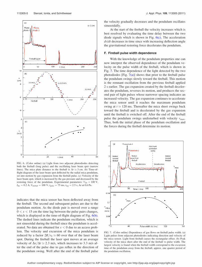
indicates that the mica sensor has been deflected away from
the fireball. The second and subsequent pulses are due to the
pendulum motion. As the diode pair is moved over a range
0 < x < 15 cm the time lag between the pulse pairs changes,
which is displayed in the time-of-flight diagram of Fig. 6(b).
The dashed lines indicate the pendulum oscillation, which is
not sinusoidal during the fireball since the pendulum is accel-
erated. No data are obtained for x < 0 due to an access prob-
lem. The velocity and excursion of the mica pendulum is
reduced by a factor 2R=r0 ’ 60 over that of the laser beam
spot. During the fireball the laser spot moves at an average
velocity of Dx=Dt ’ 2:3 m/s, which increases to 3:3 m/s af-
ter the end of the pulse due to gas reflux in the direction of
the pendulum swing. Well after the end of the fireball pulse
the velocity gradually decreases and the pendulum oscillates
sinusoidally.
At the start of the fireball the velocity increases which is
best resolved by evaluating the time delay between the two
diode signals which is shown in Fig. 6(c). The acceleration
dv/dt decreases in time since with increasing deflection angle
the gravitational restoring force decelerates the pendulum.
F. Fireball pulse width dependence
With the knowledge of the pendulum properties one can
now interpret the observed dependence of the pendulum ve-
locity on the pulse width of the fireball, which is shown in
Fig. 7. The time dependence of the light detected by the two
photodiodes [Fig. 7(a)] shows that prior to the fireball pulse
the pendulum swings slowly toward the fireball. This motion
is the remnant oscillation from the previous fireball applied
2 s earlier. The gas expansion created by the fireball deceler-
ates the pendulum, reverses its motion, and produces the sec-
ond pair of light pulses whose narrower spacing indicates an
increased velocity. The gas expansion continues to accelerate
the mica sensor until it reaches the maximum pendulum
swing at t ’ 120 ms. Thereafter the mica sheet swings back
toward the fireball and is decelerated by the gas expansion
until the fireball is switched off. After the end of the fireball
pulse the pendulum swings undisturbed with velocity vmax.
Thus, both the initial phase of the pendulum oscillation and
the forces during the fireball determine its motion.
FIG. 6. (Color online) (a) Light from two adjacent photodiodes detecting
both the fireball (long pulse) and the oscillating laser beam spot (narrow
lines). The mica plate distance to the fireball is Dr ’ 3 cm. (b) Time-of-
flight diagram of the laser beam spot deflected by the radial mica pendulum,
set into motion by gas expansion from the fireball pulse. (c) Velocity of the
laser beam spot, which is increased by the gas pressure and decreased by the
restoring force of the pendulum. Experimental parameters: Vdis ¼ 100 V,
Idis ¼ 0:2 A, Vfireball ¼ 100 V, tpulse ¼ 75 ms, trep ¼ 2:5 s, Ar at 0.6 Pa.
FIG. 7. (Color online) Dependence of gas flows on fireball pulse width. (a)
Light pulses from adjacent photodiodes indicating direction and velocity of
the mica sensor. Light from fireball causes the rectangular offset. (b) Peak
velocity of the mica sheet after the end of the fireball vs pulse width. The
largest velocity is found when the fireball width correspond to the excursion
time of the pendulum away from the fireball, approx. one quarter period of
the pendulum oscillation.
113305-5 Stenzel, Ionita, and Schrittwieser J. Appl. Phys. 109, 113305 (2011)
Author complimentary copy. Redistribution subject to AIP license or copyright, see http://jap.aip.org/jap/copyright.jsp

The peak velocity after the fireball pulse varies with
pulse width as shown in Fig. 7(b). For very short pulses
(t < 10 ms) the gas heating, hence the force on the pendu-
lum, are negligible. The largest velocity is observed when
the pulse width is approximately one quarter of the pendu-
lum period, provided the pendulum starts from at rest. When
the pulse length equals approximately half the pendulum pe-
riod the acceleration during the motion away from the fire-
ball is canceled during the back swing toward the fireball
when it moves against the gas flow.
G. Multiple fireball pulses
Successively repeated fireball pulses can influence the
pendulum motion constructively or destructively. An exam-
ple for a double pulse is shown in Fig. 8. For comparison,
Fig. 8(a) starts with a single pulse which simply sets the pen-
dulum into motion, indicated by repeated light pulses as the
laser beam spot swings back and forth over the two photodi-
odes. When a second identical fireball pulse is added with a
delay equal to half a pendulum period its force stops the
return motion of the pendulum since there are no subsequent
oscillations [Fig. 8(b)]. The effect is similar to that of a long
pulse of width equal to a half period of the pendulum oscilla-
tion except that two discrete puffs of gas have been
produced.
When the repetition time of the two pulses is increased
to one pendulum period the oscillation is constructively
enhanced. When a continuous train of pulses with
Trep ¼ Tperiod is applied the pendulum is driven resonantly to
large amplitudes.23 This amplification permits sensitive
measurements of small gas flows. When the pulse frequency
is tuned through the pendulum resonance the pendulum
reverses phase.
H. Gas expansion and contraction
The above results have clearly demonstrated that neutral
gas expands when a fireball is turned on. When now show
that a reverse gas flow is created when the fireball is turned
off and the gas streams back into the volume occupied by the
earlier fireball. Depending on the direction of motion the
pendulum may be accelerated or decelerated by the return
flow.
Figure 9 demonstrates in detail the acceleration and
deceleration of the axial pendulum by a pulsed fireball. At
the turn-on of the fireball the outflow of gas repels the mica
sheet from the fireball (see sketch at top). This causes the
laser beam spot to move from photodiode 2 to 1. The laser
beam spot passes over the diode 1, reaches its maximum
excursion, and crosses again diode 1 as the pendulum swings
back. The large excursion is caused by the acceleration due
to the gas outflow. As the pendulum returns it moves against
the flow and is decelerated. It reaches diode 2 but does not
swing beyond it since there is no second pulse from diode 2.
Continued outflow accelerates the pendulum away from the
fireball such that the beam passes again over diode 1 produc-
ing its third pulse.
Near the maximum excursion (t ’ 150 ms) the fireball
is switched off. As the pendulum swings back toward the
fireball its velocity increases as indicated by the narrow
pulse width for the fourth pulse on diode 1. The beam also
FIG. 8. (Color online) Light from two adjacent photodiodes due to multiple
short fireball pulses (large peaks) and due to the oscillating laser beam (adja-
cent double pulses). (a) A single fireball pulse causes the mica pendulum to
oscillate repeatedly. (b) When a second fireball, delayed by one half period
of the pendulum oscillation, is applied the resultant gas pressure stops the
return swing of the pendulum and no further oscillations are observed.
FIG. 9. (Color online) Acceleration and deceleration of the mica pendulum
during a long fireball pulse. Acceleration occurs when the pendulum swings
in the direction of the gas flow. The highest velocity is observed after the
end of the fireball due to the added acceleration from the gas flowing back to
the fireball after switch-off.
113305-6 Stenzel, Ionita, and Schrittwieser J. Appl. Phys. 109, 113305 (2011)
Author complimentary copy. Redistribution subject to AIP license or copyright, see http://jap.aip.org/jap/copyright.jsp

passes diode 2, overshoots it and returns to produce another
signal on diode 2. The close spacing between the two diode
signals also confirms the high speed of the laser spot
(vmax ’ 0:43 m/s).
The observation of a strong acceleration after the end of
the fireball confirms that gas streams back toward the fire-
ball. Gas heating during the fireball had created a density
depression. After the fireball pulse the gas cools which cre-
ates a pressure minimum that is equilibrated by a return flow
of ambient gas.
A fireball is a localized discharge around an electrode.
The ambient plasma is also created by a finite discharge,
although of much larger size. Thus, gas flows should also be
produced by a pulsed discharge plasma without fireballs.
Indeed, the sensitive pendulum detector indicates gas flows
at axial distances of 1 m from the filamentary cathode. Fig-
ure 10 shows the signals from the two photodiodes arranged
as shown schematically on the top. The rest position of the
laser beam spot is between both diodes.
The discharge current has a square waveform of low
repetition rate since the pendulum is weakly damped. At the
turn-off of the discharge the laser beam spot is deflected first
toward diode 1, then toward diode 2. Since there are no
repeated pulses on either diode the light beam does not over-
shoot beyond each diode. The laser beam was initially
between the diodes. Its deflection toward diode 1 implies a
gas return flow toward the decaying plasma source. The sub-
sequent pendulum oscillations decay very slowly indicating
little friction and no steady state gas flows. At the turn-on of
the discharge (t ’ 6 s) the laser beam spot happens to be on
diode 2 such that the pendulum begins to move toward the
discharge. The expanding gas from the discharge decelerates
this motion since the laser beam barely deflects toward diode
1 which results in a small diode signal. The subsequent small
diode signals show that the gas flow at turn-on has reduced
the pendulum oscillations produced at the turn-off. The tran-
sient gas flows are in opposite directions, away from the dis-
charge at turn-on, toward the discharge at turn-off, just like
in fireballs.
The mica sensor has a remarkable sensitivity which can
also detect pressure fluctuations in the background gas with-
out a discharge. It is evident that the ratio of the peak signals
from diode 1 and diode 2 varies, implying that the center
position of the beam shifts in time or the pendulum rest posi-
tion is randomly deflected due to gas flows. Small gas fluctu-
ations can be caused by the vacuum pumps and/or leak
valve.
I. Diverging and collimated flows
In order to map the flow field it would be desirable to
have a movable sensor. However, a mica pendulum is not
easily movable due to the laser beam alignment and port
access. Thus, it was easier to move the electrode which pro-
duces the fireball. A double-sided 2 cm diameter disk with-
out constricting tube, movable in axial and radial directions,
was first used to produce nearly spherical fireballs. Figure 11
shows that the mica sheet is deflected away from the fireball
on either side of the fireball. The delay between the two
diode signals is almost identical for both cases, but the direc-
tion of deflection is reversed. Because of the spherical sym-
metry of fireballs the gas flow is therefore radially outward,
except for a shadow behind the electrode. The radially
diverging flow must be transient to satisfy particle conserva-
tion without sources r � ðnvÞ þ @n=@t ¼ 0.
For some applications it would be desirable to produce a
collimated gas flow. This can be partly accomplished by pro-
ducing a fireball in a container, which prevents radial gas
flows. For this purpose the disk electrode has been inserted
into a glass cylinder as shown in Fig. 2. For a small recession
depth a spherical fireball still forms at the end of the cylin-
der. But when the electrode is recessed by about two tube
diameters (’ 4 cm for a 1.8 cm diameter tube) a long
FIG. 10. (Color online) Gas flows in a pulsed discharge without fireballs. At
turn-off of the discharge current Idis, the pendulum is accelerated toward the
discharge due to gas cooling. At turn-on the beam deflection and geometry
(see sketch on top) indicates a gas flow away from the plasma caused by gas
heating.
FIG. 11. (Color online) Radial flow from a spherical fireball is demonstrated
by placing the fireball on opposite sides of the mica pendulum. The laser
light pulses show opposite directions of pendulum motion with similar
speeds. Distance between fireball and axial mica sensor Dz ¼ 5 cm.
113305-7 Stenzel, Ionita, and Schrittwieser J. Appl. Phys. 109, 113305 (2011)
Author complimentary copy. Redistribution subject to AIP license or copyright, see http://jap.aip.org/jap/copyright.jsp

cylindrical fireball is formed. No magnetic field is applied.
For a fireball current I ¼ 1 A, electrode area A ¼ 2:5 cm2
and kTe ’ 10 eV the density inside the gun is ne ’4:6� 1010 cm�3. By varying the electrode voltage the fire-
ball can be terminated at the opening of the tube. In such a
“fireball gun” the heated gas can only escape axially in one
direction. With a gas feed into the tube a steady-state flow
can possibly be achieved.
In order to measure the gas flow as a function of angle
the gun is rotated horizontally while the radial mica sensor
remains fixed. Figure 12(a) shows a polar plot of the velocity
of the mica sensor due to the hot gas escaping from the fire-
ball. The gas flow peaks along the gun axis with a half width
of ’ 30�. Such a directional gas flow is far more intense than
that from a spherical fireball. Figure 12(b) shows that a wire
crossing the fireball is heated and glows red (Twire ’ 500� C).
Assuming that the heating is caused by hot neutrals from the
fireball their temperature must well exceed that of the wire
since the pulsed heating occurs at a low duty cycle
(ton=toff ¼ 0:1 s=2 s ¼ 5%). Further work on heat transport is
needed for new fireball applications.
IV. CONCLUSIONS
Neutral gas flows in pulsed fireballs and discharges have
been investigated experimentally. The main diagnostic tool
is a mica sensor, which is deflected by gas flows. The pendu-
lum properties have been demonstrated so as to interpret the
gas dynamics in fireballs. Heating and cooling of gas causes
gas flows which have been measured for various pulse condi-
tions. The flows from a spherical fireball are radially diverg-
ing but can be partially collimated by a cylindrical fireball
gun. High neutral gas temperatures are observed in the gun
outflow regions.
These initial observations may open up a variety of fur-
ther studies and applications. For example, the role of neu-
trals in the transfer of momentum and energy in fireball
plasmas has not received much attention. Neutral burn-out in
high current fireballs and resulting instabilities should be
investigated. Since fireballs produce measurable pressure
pulses low frequency sound waves can be excited with fire-
balls in plasmas whose dimensions exceed the sound
wavelength.
Applications of gas flows include simple mechanical
devices like the present pendulum, rotations like the
Crooke’s radiometer, convection of dust particles, possible
nanometer structures, drag of ions, etc. Flows can be used to
pump gas, separate different gases, deposit gas on surfaces,
perform plasma chemistry at high temperatures. The present
sensor could be miniaturized for improved flow measure-
ments at pressures < 0:1 Pa.
ACKNOWLEDGMENTS
One of the authors (R.L.S.) gratefully acknowledges
support and hospitality while staying as guest professor at
the University of Innsbruck. This work was supported in part
by the Austrian Science Funds (FWF) under Grant No.
P19901 and in part by NSF/DOE Grant DE-SC0004660.
1J. G. Luhmann, Space Sci. Rev. 34, 1531 (1983).2T. D. Arber, G. J. J. Botha, and C. S. Brady, Astrophys. J. 705, 1183
(2009).3H. P. Larsona, H.-Y. Hub, K. C. Hsieh, H. A. Weaver, and M. J. Mumma,
Icarus 91, 251 (1991).4B. Lehnert, Astrophys. Space Sci. 55, 25 (1978).5L. Lengyel, R. Schneider, O. Kardaun, R. Burhenn, H. Zehrfeld, I. Vese-
lova, I. Senichenkov, V. Rozhansky, and P. Lalousis, Contrib. Plasma
Phys. 48, 623 (2008).6L. Schmitz, B. Merriman, L. Blush, R. Lehmer, R. W. Conn, R. Doerner,
A. Grossman, and F. Najmabadi, Phys. Plasmas 2, 3081 (1995).7Y. Tao, M. S. Tillack, S. S. Harilal, K. L. Sequoia, B. O’Shay, and F. Naj-
mabadi, J. Phys. D 39, 4027 (2006).8J. Gilland, R. Breun, and N. Hershkowitz, Nucl. Fusion 7, 416 (1998).9G. R. Tynan, J. Appl. Phys. 86, 5356 (1999).
10D. D. Hsu and D. B. Graves, J. Phys. D 36, 2898 (2003).11P. K. Shukla and F. Verheest, Astrophys. Space Sci. 262, 157 (1998).12K. G. Emeleus, Int. J. Electron. 52, 407 (1982).13M. Sanduloviciu and E. Lozneanu, Plasma Phys. Controlled Fusion 28,
585 (1986).14B. Song, N. D.’Angelo, and R. L. Merlino, J. Phys. D 24, 1789 (1991).15L. Conde and L. Leon, Phys. Plasmas 1, 2441 (1994).16T. Gyergyek, M. Cercek, R. Schrittwieser, and C. Ionita, Contrib. Plasma
Phys. 42, 508 (2002).17R. L. Stenzel, C. Ionita, and R. Schrittwieser, Plasma Sources Sci. T. 17,
035006 (2008).18S. D. Baalrud, B. Longmier, and N. Hershkowitz, Plasma Sources Sci. T.
18, 035002 (2009).19C. Ionita, D. Dimitriu, and R. Schrittwieser, Int. J. Mass Spectrom. 233,
343 (2004).20A. V. Phelps, C. H. Greene, and J. P. Burke, Jr., J. Phys. B 33, 2965 (2000).21A. V. Phelps, J. Phys. Chem. Ref. Data 20, 557 (1991).22G. G. Raju, IEEE Trans. Dielectr. Electr. Insulation 11, 649 (2004).23Movie of a pendulum with electrode driven resonantly by pulsed fireballs
on the left side of the electrode, http://www.physics.ucla.edu/plasma-exp/
research/Gasdynamics/index.html.24W. Crookes, Philos. Trans. R. Soc. London 164, 501 (1874).25Z. Lu, J. Vac. Sci. Technol. A 23, 1531 (2005).
FIG. 12. (Color online) Properties of a fireball gun. (a) Polar plot of the ve-
locity of a mica sensor due to gas flow from the fireball. (b) Picture of the
fireball gun aimed at an oxide-coated wire, which is heated by fireball neu-
trals to emission temperatures.
113305-8 Stenzel, Ionita, and Schrittwieser J. Appl. Phys. 109, 113305 (2011)
Author complimentary copy. Redistribution subject to AIP license or copyright, see http://jap.aip.org/jap/copyright.jsp