neville harnew - university of oxford
TRANSCRIPT

TORCH: A large-area detector for precision time-of-flight measurements
Neville HarnewUniversity of Oxford
ON BEHALF OF THE TORCH COLLABORATION
(Bristol, CERN, Oxford)

2Fast Timing Workshop, Erice 20-22 November 2013 N.Harnew
Outline
Introduction: what is the TORCH detector? Concept & principles
TORCH R&D activities Customized Micro-channel Plate detectors (MCPs) Readout electronics
Application for the LHCb upgrade
Summary and future plans

3Fast Timing Workshop, Erice 20-22 November 2013 N.Harnew
1. Introduction The TORCH (Time Of internally Reflected CHerenkov
light) detector is an R&D project to develop a large-area time-of-flight system.
TORCH combines timing information with DIRC-style reconstruction (cf. the PANDA DIRC and Belle TOP detectors) - aiming to achieve 10–15 ps (per track) TOF resolution.
One application is for low-momentum (<~10 GeV/c) particle identification for the upgrade of LHCb, the dedicated flavour experiment at the LHC.
A 4-year grant for R&D on TORCH has been awarded by the ERC: to develop customised photon detectors in collaboration with industrial partners and to provide proof-of-principle with a prototype module.

4Fast Timing Workshop, Erice 20-22 November 2013 N.Harnew
25 ns
Photon arrival time
TORCH concepts & principles (1)
To achieve positive identification of kaons up to p ~ 10 GeV/c, TOF (-K) = 35 ps over a ~10 m flight path → need to aim for ~15 psresolution per track
Cherenkov light production is prompt → use a plane of quartz as source of a fast signal
Cherenkov photons travel to the periphery of the detector by total internal reflection → time their arrival with fast PMTs : Multi-Channel Plate detectors (MCPs)
Spread of arrival times span ~25ns (the LHC bunch crossing time) due to different paths taken by photons in the plate
Four tracks distributed at points
around the plate
5Fast Timing Workshop, Erice 20-22 November 2013 N.Harnew
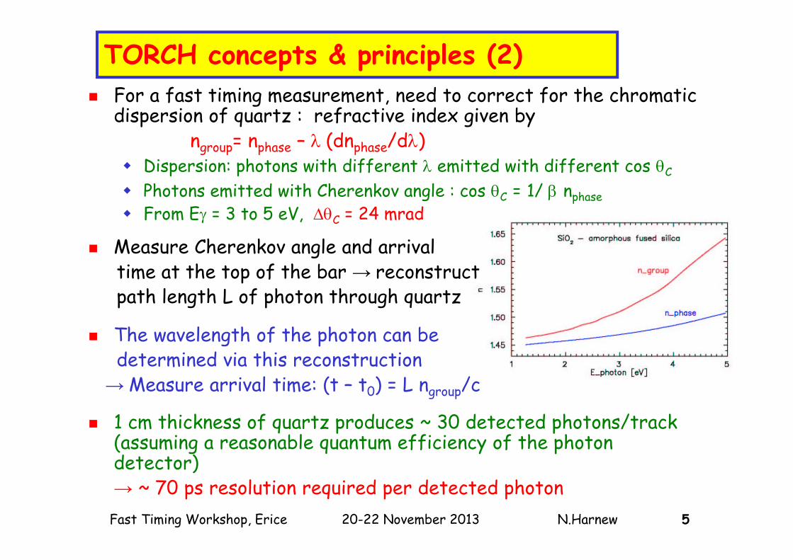
TORCH concepts & principles (2) For a fast timing measurement, need to correct for the chromatic
dispersion of quartz : refractive index given by ngroup= nphase – (dnphase/d)
Dispersion: photons with different emitted with different cos C
Photons emitted with Cherenkov angle : cos C = 1/ nphase From E = 3 to 5 eV, C = 24 mrad
Measure Cherenkov angle and arrival time at the top of the bar → reconstruct path length L of photon through quartz
The wavelength of the photon can be determined via this reconstruction
→ Measure arrival time: (t – t0) = L ngroup/c
1 cm thickness of quartz produces ~ 30 detected photons/track (assuming a reasonable quantum efficiency of the photon detector) → ~ 70 ps resolution required per detected photon

6Fast Timing Workshop, Erice 20-22 November 2013 N.Harnew
Angular measurement (x) Need to measure angles of photons: their path length can then be reconstructed From simulation, ~1 mrad precision required on the angles in both planes for intrinsic
resolution of ~50 ps Typical lever arm ~ 2 m Angular resolution ≈ 1 mrad x 2000 mm / √12 Coarse segmentation (~6 mm) sufficient for the transverse direction (x) ~8 pixels of a “Planacon-sized” MCP of 53x53 mm2 active dimension
x
z
z
c
L =h/cos z

7Fast Timing Workshop, Erice 20-22 November 2013 N.Harnew
Angular measurement (z) Measurement of the angle in the longitudinal direction (z) requires a
quartz (or equivalent) focusing block to convert angle of photon into position on photon detector
Cherenkov angular range = 0.4 rad angular resolution ~ 1 mrad: need ≈ 400/ (1 x √12) ~ 128 pixels fine segmentation needed along this direction
Representative photonpaths: 0.55 < z < 0.95 rad

8Fast Timing Workshop, Erice 20-22 November 2013 N.Harnew
TORCH modular design Dimension of quartz plane is ~ 5 6 m2 (at z = 10 m) Unrealistic to cover with a single quartz plate evolve to modular
layout 18 identical moduleseach 250 66 1 cm3
each with 11 MCPs to cover the length
Possibility of reflective lower edge increase the number of photons
MCP photon detectors at the top and bottom edges18 11 = 198 unitsEach with 1024 pads 200k channels total

9Fast Timing Workshop, Erice 20-22 November 2013 N.Harnew
Event display Event topology in
TORCH detectorfrom simulation of sterile neutrinosDNX, N
Photons colour-coded to matchtheir parent track
Track impact points
on quartz plate
Photon impact pointson detectors along
each edge (z vs. x)without dispersion or
modularity

10Fast Timing Workshop, Erice 20-22 November 2013 N.Harnew
Simulation of accumulated photons for a thousand 10 GeV/c kaons Background photons from secondary electrons that also give off Cherenkov
radiation Width of Cherenkov ring segment is due to chromatic dispersion in quartz
medium
Full GEANT simulations underway

11Fast Timing Workshop, Erice 20-22 November 2013 N.Harnew
2. TORCH R&D 4-year ERC TORCH R&D project started 18 months ago
(collaboration between CERN, Bristol and Oxford Universities)
A major focus is on MCP R&D with industrial partner: Photek (UK). Three phases defined: I. MCP extended lifetime (> 5 C/cm2 required for LHCb)
- focuses on extended lifetime using ALD coating
II. MCP with customised granularity (128×8 pixels or equivalent) - Modelling studies under way towards achieving required
granularity for Phase II64 × 8 may be sufficient if charge-sharing between neighbouringpads can be used
III. Square tubes with high active area (> 80%)
Also need to design for high occupancy in LHCb ~ 30 hits/detector/event (≈ every 25 ns)

12Fast Timing Workshop, Erice 20-22 November 2013 N.Harnew
• Micro-channel plate (MCP) photon detectors are suitable for fast timing of single photon signals. Tube lifetime is an issue.
• Anode pad structure can in principle be adjusted according to resolution required, as long as charge footprint is small enough
• Highest granularity commercially-available MCP is the 32x32 Planacon from Photonis
• TORCH needs a linear array of photon detectors with adapted pixel size: 128 × 8 pixelsDevelopment of suitable detector with this layout is a focus of the R&D with industrial partners Photek (UK)
32 × 32 channel Planacon
Overview of MCP requirements
FaceplatePhotocathode
Dual MCP
Anode
Gain ~ 106
photoelectron V ~ 200V
V ~ 200V
V ~ 2000V
photon
FaceplatePhotocathode
Dual MCP
Anode
Gain ~ 106
photoelectron V ~ 200V
V ~ 200V
V ~ 2000V
photon
~10-25 um pores
13Fast Timing Workshop, Erice 20-22 November 2013 N.Harnew
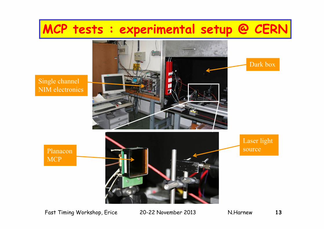
MCP tests : experimental setup @ CERN
Single channel NIM electronics
Dark box
PlanaconMCP
Laser light source
14Fast Timing Workshop, Erice 20-22 November 2013 N.Harnew
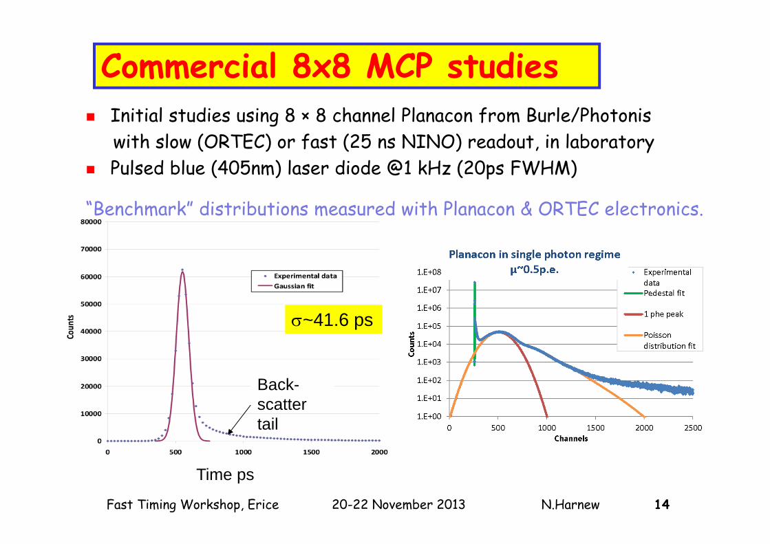
Commercial 8x8 MCP studies
Test-beam setup
Back-scatter tail
~41.6 ps
Time ps
Initial studies using 8 × 8 channel Planacon from Burle/Photoniswith slow (ORTEC) or fast (25 ns NINO) readout, in laboratory
Pulsed blue (405nm) laser diode @1 kHz (20ps FWHM)
“Benchmark” distributions measured with Planacon & ORTEC electronics.

15Fast Timing Workshop, Erice 20-22 November 2013 N.Harnew
Photek Phase I: MCP lifetime & timing
4 single-channel MCPs produced by Photek and tested in-house and by the TORCH collaboration
Again use single-channel ORTEC electronics
Pulse height spectra: Standard Poisson distribution to fit data Average number of photoelectrons per pulse
(μ) inferred from P(0)
Timing jitter distributions: Exponentially-modified Gaussian distribution to fit
prompt peak time resolution (σ)
Photek MCP

16Fast Timing Workshop, Erice 20-22 November 2013 N.Harnew
Photek tube PMT225/SN G1130614

17Fast Timing Workshop, Erice 20-22 November 2013 N.Harnew
Improved MCP lifetime[T M Conneely, J S Milnes (Photek Ltd), Vienna Conference on Instrumentation, March 2013] Use atomic Layer Deposition (ALD)
techniques to coat atomic mono-layers onto the MCP.
This improves secondary emission giving significantly higher gain for the same HV
Also prevents desorption of gaseous contaminants in the MCP glass (cause of ageing in MCP).
Accelerated life testing at Photek using a DC light source : MCP photocurrent monitored @ gain of 1×10⁶.
The ALD coated MCPs significantly outperforms the uncoated MCPs for lifetime (good up to beyond 5.1 C cm-2)
The photocathode’s quantum efficiency does not change.
NB. Early Photek demonstrators (not
TORCH tubes)

18Fast Timing Workshop, Erice 20-22 November 2013 N.Harnew
Phase II MCP R&D : customized pad layout
Traditional multi-anode manufacturing uses multiple pins: unrealistic for a 128 x 8 array
Aim is to use multilayer ceramic with filled vias
The pads on this design are 0.75 mm wide on a 0.88 mm pitch; contact made to anodes by Anisotropic Conductive Film (ACF)
Charge division between a pair of pads can improve resolution and reduce total number of channels
External PCB will house front-end electronics

19Fast Timing Workshop, Erice 20-22 November 2013 N.Harnew
Readout Electronics Readout electronics is crucial component
to achieve desired resolution.Suitable front-end chip has been developed for the ALICE TOF system: NINO + HPTDC [F. Anghinolfi et al., Nucl. Instr. and Meth. A 533, (2004), 183]
Currently using 8 channel versions, 32-channel available, ~ 10 fC threshold [M. Despeisse et al., IEEE 58 (2011) 202]
Provides time-over-threshold informationwhich is used to correct time walk(+ measure the charge, for charge-sharing)
NINO chips
2 NINO chips Planacon

20Fast Timing Workshop, Erice 20-22 November 2013 N.Harnew
Data flow
16 channels per board Laboratory and test-beam firmware have been developed Delay matched PCB tracks across all channels On board test signal injection Giga-bit Ethernet-based readout for up to 4 Front-End boards Readout system also provides NINO threshold control and HPTDC
configuration.
21Fast Timing Workshop, Erice 20-22 November 2013 N.Harnew
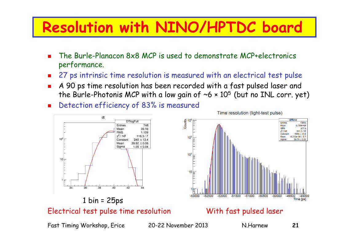
Resolution with NINO/HPTDC board
The Burle-Planacon 8x8 MCP is used to demonstrate MCP+electronicsperformance.
27 ps intrinsic time resolution is measured with an electrical test pulse A 90 ps time resolution has been recorded with a fast pulsed laser and
the Burle-Photonis MCP with a low gain of ~6 × 10⁵ (but no INL corr. yet) Detection efficiency of 83% is measured
1 bin = 25ps Electrical test pulse time resolution With fast pulsed laser

22Fast Timing Workshop, Erice 20-22 November 2013 N.Harnew
3.TORCH application : the LHCb Upgrade
RICH-1
TORCH upgrade
pp
10 – 300 mrad
Upgrade of LHCb will increase data rate by an order of magnitude to run at luminosity 1–2 × 1033 cm-2 s-1, for running in 2019
Read out complete experiment at 40 MHz, fully software trigger RICH system will be retained for particle ID, but aerogel radiator
removed since it is ineffective at high lumi. The plan is to install TORCH, taking space from muon station M1
RICH-2

23Fast Timing Workshop, Erice 20-22 November 2013 N.Harnew
Example of direct CP violation measurement (> 6) observation in B0K+π-
Separate samples into B0 and B0 using particle identification from RICH
An example of the need for good PID

24Fast Timing Workshop, Erice 20-22 November 2013 N.Harnew
TORCH expected performance at LHCb Simulate the TORCH detector & interface to a
simulation of LHCb events, plus TORCH pattern recognition
Obtain a start time t0 from the other tracks in the event originating from the primary vertex
The intrinsic arrival time resolution per photon is 50 ps giving a total resolution of: 40 ps [MCP] 50 ps [intrinsic] 70 ps(as required)
Excellent particle ID performanceachieved, up to and beyond 10 GeV/c (with some discrimination up to 20 GeV/c).Robust against increased luminosity:See also Letter of Intent for the LHCbupgrade [CERN-LHCC-2011-001]
Full GEANT simulation of TORCH is in progress, and optimization of the modular layout
LHCb Simulation
Effic
ienc
y
(Ideal reconstruction, isolated tracks)
25Fast Timing Workshop, Erice 20-22 November 2013 N.Harnew
4. Summary & future plans TORCH is a novel concept for a DIRC-type detector
to achieve high-precision time-of-flight over large areas.
Given a per-photon resolution of 70 ps, excellent K-separation can be achieved up to 10 GeV/c and beyond (with a TOF resolution of ~15 ps per track)
Ongoing R&D programme aims to produce suitable MCP within next 2.5 years, satisfying challenging requirements of lifetime, granularity, and active area. A prototype module will demonstrate the concept.
TORCH Proposal for the LHCb Upgrade to be submitted on completion of successful R&D phase.
And one last footnote …

26Fast Timing Workshop, Erice 20-22 November 2013 N.Harnew
Possible re-use of BaBar quartz bars BaBar DIRC quartz bars are available following SuperB cancellation : made up
of 12 planar ‟bar-boxesˮ each containing 12 quartz bars 1.7 x 3.5 x 490 cm3
Bar length (at z = 950 cm ) and total area ~ 30 m2 matches TORCH needs. Adapting the bars requires focusing in both projections; can use a cylindricallens for this, at the end of each bar.
Effect of wedge (glued to bars) is to give two separate beams: depending on whether photons reflected or not.
Split detector plane: assuming 60 mm square MCPs (53 mm active) requirestwo PMTs to cover 0.5 < z < 0.9 rad
Adapting the TORCH optics to re-use the BaBar DIRC seems viable: no degradation seen compared with single projection. Studies are ongoing.