nevis synchrocyclotron conversion project · pdf fileoil-cooled main current ... the original...
TRANSCRIPT

Nevis synchroc yclotron conversion project * R. Cohen, E. Martin,? J. Rainwater, R. Schneider, K. ZieglerS Columbia University, New York, U.S.A.
and S. Ohnuma Yale University, New Haven, U. S.A.
Presented by J. Rainwater
ABSTRACT
The status of the Columbia University Nevis Synchrocyclotron Modification Project is presented here. The machine will be converted to a three-fold symmetry spiral sector focusing AVF synchrocyclotron, having a long duty factor 550 MeV external proton beam. The time average external beam intensity is expected to be between 5 pA and 40 pA. The accelerating rf must cover the frequency band from -- 26.5 MHz to 18.5 MHz. One of the three pairs of sector iron shims will be incorporated in the dee and supported on A1203 insulators. Tuning will be accomplished by two rotating capacitors with axes directed toward the centre of the magnet. This design permits effective magnetic shielding of the rotor to minimise eddy current losses. The reasons leading to the particular approach of this conversion programme are given.
1. INTRODUCTION
The Columbia University Nevis Synchrocyclotron was planned and constructed before 1950. It presently produces only an internal beam of protons which are accelerated to -380 MeV at 70 Hz repetition cycle rate and - 1.5 pA time average current. Present operation mainly uses a Be vibrating (internal) target to give long duty factor external pion and muon beams via the cyclotron fringe field focusing properties. It is also used for pulsed neutron time-of-flight spectroscopy.
Planning for the revision programme began in 1965 and completion of the conversion is expected during 1971. Earlier descriptions of our revision planning extend back to the College of William and Mary Conference on High
* Research supported in part by the National Science Foundation. t On leave from Institut de Physique NuclBaire (Orsay), France. 8 On leave from the University of Heidelberg, Germany.
Proceedings of the Fifth International Cyclotron Conference
CYC69H03

Energy Cyclotron Improvement.' The most recent description is given in a series of papers at the 1969 Particle Accelerator Conference held in Washington, D.C.' The conversion programme is now reaching the stage where orders for the major components are being placed. The conversion will change the machine to a 550 MeV machine having long duty factor (5-40 pA time average) external beam facility. The building extension was finished last year.
1
2. STATUS OF THE CONVERSION PROJECT
Plans call for retention of the basic 2000-ton steel magnet and the present oil-cooled main current excitation coils. Pole iron within 30 in of the median plane will be replaced by new iron which will provide a three-fold symmetrical azimuthally varying field (AVF) for the beam. The system will remain a synchrocyclotron rather than become a fixed frequency (CW) machine. The azimuthal average magnetic field <B > will increase from -- 17 kG near the centre to -20 kG near 80 in radius. This implies a reduced FM frequency range for the dee from -26.5 MHz at injection to -1 8.5 MHz at maximum energy. Additional field excitation will be provided by the addition of new 'auxiliary' magnet coils between the main coils and outside the 170-in pole diam. These coils will carry about half as many ampere turns excitation as the main coils. Due to their position, these coils will be much more effective, per ampere turn, than the main coils in producing a high magnetic field at large radius by reducing fringe field effects.
The original plans envisaged mounting the auxiliary coils in vacuum inside the new larger cyclotron vacuum chamber. We have, however, arrived at a chamber design which has doughnut-shaped recesses, top and bottom, on the outside of the chamber so that the coils will be topologically outside (Fig. 1).
Fig. l . Side view o f the iron configuration for the modified Nevis Synchrocyclotron (suggestive)
Proceedings of the Fifth International Cyclotron Conference
CYC69H03
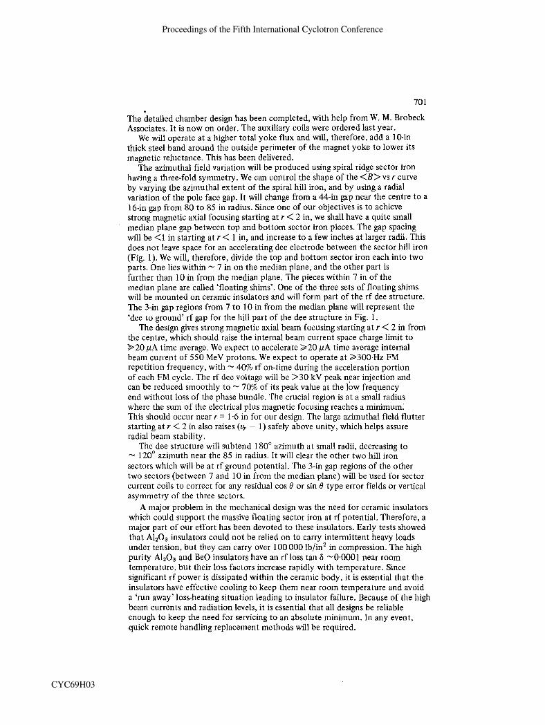
The detailed chamber design has been completed, with help from W. M. Brobeck Associates. It is now on order. The auxiliary coils were ordered last year.
We will operate at a higher total yoke flux and will, therefore, add a 10-in thick steel band around the outside perimeter of the magnet yoke to lower its magnetic reluctance. This has been delivered.
The azimuthal field variation will be produced using spiral ridge sector iron having a three-fold symmetry. We can control the shape of the <B> vs r curve by varying the azimuthal extent of the spiral hill iron, and by using a radial variation of the pole face gap. It will change from a 44-in gap near the centre to a 16-in gap from 80 to 85 in radius. Since one of our objectives is to achieve strong magnetic axial focusing starting at r < 2 in, we shall have a quite small median plane gap between top and bottom sector iron pieces. The gap spacing will be <l in starting at r < 1 in, and increase to a few inches at larger radii. This does not leave space for an accelerating dee electrode between the sector hill iron (Fig. 1). We will, therefore, divide the top and bottom sector iron each into two paris. o n e lies within - 7 in on the median plane, and the other part is further than 10 in from the median plane. The pieces within 7 in of the median plane are called 'floating shims'. One of the three sets of floating shims will be mounted on ceramic insulators and will form part of the rf dee structure. The 3-in gap regions from 7 to 10 in from the median plane will represent the 'dee to ground' rf gap for the hill part of the dee structure in Fig. 1.
The design gives strong magnetic axial beam focusing starting at r < 2 in from the centre, which should raise the internal beam current space charge limit to >20 pA time average. We expect to accelerate 2 2 0 pA time average internal beam current of 550 MeV protons. We expect to operate at 2 3 0 0 . H ~ FM repetition frequency, with - 40% rf on-time during the acceleration portion of each FM cycle. The rf dee voltage will be >30 kV peak near injection and can be reduced smoothly to - 70% of its peak value at the low frequency end without loss of the phase bundle. The crucial region is at a small radius where the sum of the electrical plus magnetic focusing reaches a minimum. This should occur near r = 1-6 in for our design. The large azimuthal field flutter starting at r < 2 in also raises (v, - 1) safely above unity, which helps assure radial beam stability.
The dee structure will subtend 180" azimuth at small radii, decreasing to - 120" azimuth near the 85 in radius. It will clear the other two hill iron sectors which will be at rf ground potential. The 3-in gap regions of the other two sectors (between 7 and 10 in from the median plane) will be used for sector current coils to correct for any residual cos 0 or sin 0 type error fields or vertical asymmetry of the three sectors.
A major problem in the mechanical design was the need for ceramic insulators which could support the massive floating sector iron at rf potential. Therefore, a major part of our effort has been devoted to these insulators. Early tests showed that ~ 1 ~ 0 ~ insulators could not be relied on to carry intermittent heavy loads under tension, but they can carry over l 0 0 000 lb/in2 in compression. The high purity A1203 and Be0 insulators have an rf loss tan 6 -0.0001 near room temperature, but their loss factors increase rapidly with temperature. Since significant rf power is dissipated within the ceramic body, it is essential that the insulators have effective cooling to keep them near room temperature and avoid a 'run away' loss-heating situation leading to insulator failure.-~ecause of the high beam currents and radiation levels, it is essential that all designs be reliable enough to keep the need for servicing to an absolute minimum. In any event, quick remote handling replacement methods will be required.
Proceedings of the Fifth International Cyclotron Conference
CYC69H03

Recently we have arrived at a superior solution to the rf support insulator cooling problem. We intend to use a hollow cylinder insulator design which has vacuum tight end pieces of metal sheet brazed to the metallised insulator ends. We shall then circulate Freon C51-12 dielectric coolant fluid through the insulators. Tests under more severe rf field conditions than we will use have shown that satisfactory results can be obtained. Insulators of this type will also be used at other places where structures at high rf voltage must be supported such as the rotating capacitor stator. A large number of the final design insulators are on order.
The main vertical magnetic forces on the floating sector iron pieces have been balanced by using a rigid 'tuning fork' metal structure connecting the top and bottom floating iron pieces beyond the 85 in radius. This is illustrated in Figs 1 and 2, which are suggestive rather than final scale drawings. The main support insulators, under compressive loads only, are beyond the 85 in radius and act on the massive metal structure. Our central region studies indicate that the first ion orbit turn, for >30 kV rf on the dee will have 2 1 in diamater. We will therefore use a non-iron metal brace to resist the magnetic forces which tend to close the l-in gap. The brace structure through the median plane will be inside the first orbit. The ion source will be positioned in the valley region at a small radius. We expect to pulse it to a value of +20 to +30 kV during injection.
We expect to operate using >300 Hz repetition rate with the rf off for -60% of each FM cycle. During this time, the long duty factor beam extraction occurs.
The planned dee-line rotating capacitor resonator system will use two rotating capacitors in parallel at the far end of the dee-line system, situated outside the magnet coils. The geometry is shown in Figs 1 and 2. The dee-line rotating capacitor system will act as a 'tuned half-wave' resonator having a voltage node before reaching the capacitors. The node moves towards the capacitors as f decreases (C increases). The system has a variable Z , (characteristic impedance) transmission line system where Zo decreases from - 4 Cl near the dee mouth to 2 C? over a region near the voltage node. A short Zo -10 i2 section is used just before the rotating capacitors. The system design was aided by extensive computer studies of various possible configurations. The programme also studied optimisation of the associated coupling system for the rf power tubes. K. MacKenzie's approach3 is used for the coupling of the power tube to the resonator.
The most troublesome undesired mode is the 'beam-excited cross mode' where opposite sides of the dee are 180' out of phase. If this mode frequency occurs at exactly twice the main mode frequency, the rotating proton bunch in the chamber will excite it. This leads to a reduction of the acceleration energy gain at each gap crossing by an amount proportional to the internal beam current. This effect was first noted at the CERN Synchrocyclotron4 and later at the Carnegie Synchrocy~lotron.~ It has also recently been observed to be a limiting factor for the SREL copy of the CERN machine.
Our plan is to lower the cross mode frequency significantly below twice the main mode frequency by adding sufficient distributed capacitance loading along the edge of the dee-line system near the dee end. This, plus extra capacitance at the dee mouth, increases the local stored charge to help reduce local dee voltage changes when the beam enters and leaves the dee. We do not expect the beam excited cross mode to be a problem with our design. We will also use other high loss cross-coupling devices to 'kill' undesired modes.
For the rotating capacitors we plan to use short rotors 48 in in diameter at the
Proceedings of the Fifth International Cyclotron Conference
CYC69H03

Fig
. 2.
Top
vie
w o
f th
e ir
on c
onfi
gura
tion
sugg
est d
ee-l
ine a
nd r
otat
ing
capa
cito
r sy
stem
for
the
mod
ifie
d N
evis
Sy
nchr
ocyc
lotr
on.
The
pos
ition
s o
f th
e ex
trac
tion
ele
men
ts: P
eele
r (P
), R
egen
erat
or (
R),
Mag
netic
Cha
nnel
(MC
), an
d T
ime
Var
ying
Mag
netic
Bum
p (T
), as
wel
l as
the
path
of
the
extr
acte
d be
am a
re a
lso
indi
cate
d
Proceedings of the Fifth International Cyclotron Conference
CYC69H03

outside of the blade circle having 4 layers of 12 blades. We first performed model studies for a rotating capacitor system having its rotor axis horizontal and perpendicular to the line to the magnet centre. We have since decided in favour of the rotor axis directed towards the dee. This scheme is presently used for the Dubna Synchrocyclotron, and is also favoured for conversion plans at CERN and at the University of California (Berkeley). This design yields the lowest rf power losses. Our rotating capacitor design differs from others in that we plan to have the stator blade ring at dee-line rf potential rather than at ground potential. The large area central rotor face will be G0.010 in from a ground face to provide a much greater capacitance from rotor to ground than from rotor to stator. This leads to a structure where the rotor drive seal and bearings are relatively near ground potential (the Dubna design has the rotor near the line rf potential). The connection of the stator ring to the dee line is via four transmission lines which extend from the end of the main vacuum chamber to the capacitor housings. The connections are at points 90" apart around the stator ring. This topology permits the use of a thick iron case for the capacitor housing. It provides almost complete magnetic shielding of the rotor from the cyclotron fringing magnetic field. This design puts the rotor drive shaft (on the chamber side) in air and readily accessible.
The capacitor voltage ranges from -90% of the dee voltage at the high frequency end to -5m of the dee voltage at the low frequency end. The stator blades will be shaped so that as the rotor blades begin to mesh, the gap is-6 mm, decreasing to -3 mm for the last half of the overlap where the voltage is low. Tests using a half-scale model of the system, including the model rotating capacitors, show that the tuning properly covers the desired frequency range.
3. THEORETICAL CONSIDERATIONS FOR OUR CONVERSION APPROACH
It may be noted that our choice of a conversion to an AVF synchrocyclotron is unique to our programme. Conversion plans for the CERN and Berkeley Synchrocyclotrons envisage retention of their magnets with no magnetic field changes. Those involved in 4 V F isochronous cyclotron design tend to regard any other approach as some kind of blasphemy. We shall attempt to indicate the logical considerations which have led to our choice, and discuss developments from our studies which relate to its feasibility.
The discussion should be related to the orbit theory in an AVF situation. The Smith-Garren formulae6 provide relatively precise expressions for the vertical (axial) focusing terms vz2, and the radial oscillation frequency, v,. The radial orbit precession frequency is up,, = I z+ - 1 l . For three-fold symmetry, the main terms in the Smith-Garren equation can be written:
where k = (r/<B>)d <B>/dr
tan y = r(dq/dr) X cp(r) is the hill azimuth angle.
Proceedings of the Fifth International Cyclotron Conference
CYC69H03

The primes represent derivatives with respect to r, and y is the magnetic field azimuth spiral angle. The < > implies an azimuthal average.
For an isochronous machine, <B> must be proportional to the total proton energy. For a 550 MeV proton machine, <B> would increase by the factor (14901940) from injection to full energy. In this case, k becomes large and positive. It contributes a strong axially defocusing term which must be more than counteracted by the subsequent focusing terms involving the field flutter factor F and its derivatives. In practice, such a design for our magnet diameter would require very large F values and as a consequence, a much lower <B> at full energy would result. An attempt to achieve full isochronism with our magnet would probably yield about half the 550 MeV energy which we shall obtain. It would be much more meaningful to start over with an order of magnitude more expensive 'Meson Factory' programme implied.
The CERN and Berkeley Synchrocyclotrons produce 600 MeV and 750 MeV protons respectively. These energies are in the region of efficient pion and muon production towards which we strive. Since our plan includes an increase of energy from 380 MeV to 550 MeV, we must alter our magnet. In the process, it is worthwhile to avail ourselves of the benefits achieved by the use of AVF.
An ordinary synchrocyclotron is a very 'weak focusing' machine. For an azimuthally symmetrical magnetic field, v; = -k and v; = ( l + k). A gradual monotonic decrease in B vs r introduces weak axial focusing (v: positive) and has v, = 1 - ~212. The precession frequency uprec = vy,2/2 is very small, and tends to increase slowly and monotonically over most of the radial region. The space charge beam current limit is determined by the ability of axial focusing terms to counteract beam space charge axial repulsion. It tends to be proportional to v: at small radius, to the FM cycle repetition frequency, and to some power of the dee rf voltage near in je~ t ion .~ The precession frequency should be reasonably large to counteract the tendency of the orbit centre to 'walk' laterally, or to have a large growth in the radial oscillation amplitude due to 'walking force effects'. These include (a) residual imperfection cos 8 or sin 8 Fourier magnetic field components; (b) the unbalanced net impulse force when <l 80' dee aperture is used; and (c) the particularly undesirable resonance effects for a <180° dee when up,, is a low order multiple of the phase oscillation frequency. The slow continuous increase of up, for an azimuthally symmetric field makes ordinary synchrocyclotrons particularly vulnerable to this last effect. Our tests indicate that we shall have v: > 0.05 and (v; - 1) 2 0.02 from r - 1.6 in to near where extraction occurs. The decrease of up,, to zero near extraction aids in achieving a high extraction efficiency.
We had the following physical parameters to vary in our 1 / l 0 scale model magnet: (a) the current in the magnet excitation coils; (b) the gap size vs radius for the 'foundation',360" iron of the pole pieces; (c) the vertical median plane gap spacing of the sector iron vs radius, including the starting radius for the sector iron; (d) the choice of the boundary position for separating the sector iron into portions nearest to the median plane ('floating iron') and that mounted on the pole tips; (e) the choice of a gap vs radius between the pole 360" iron and the sector iron nearest to the 360" iron; (Q the choice of the azimuthal angle to be subtended by the sector iron vs radius; and (g) the spiral angle shape of the sector iron vs radius. For a machine with an azimuthally symmetrical field, only the parameters (a) and (b) are involved.
Our model studies have achieved a shim configuration which gives essentially the desired <B>, F, and tan y vs r. A set of parameters giving stable orbits at all radii is depicted in Fig. 3.
Proceedings of the Fifth International Cyclotron Conference
CYC69H03
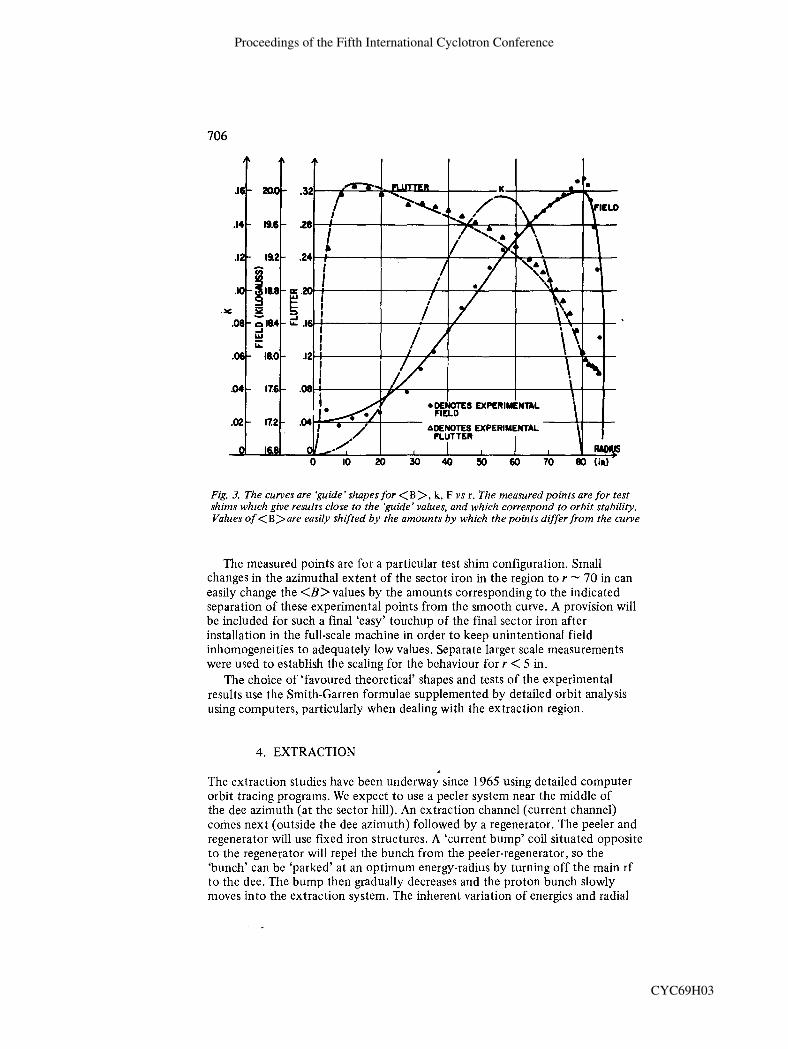
Fig. 3. The curves are 'guide' shapes for <B >, k , F vs r . The measured points are for test shims whzch give results close to the 'guide' values, and which correspond to orbit stability. Values o f <B>are easily shifted by the amounts by which the points differ from the curve
The measured points are for a particular test shim configuration. Small changes in the azimuthal extent of the sector iron in the region to r -- 70 in can easily change the <B> values by the amounts corresponding to the indicated separation of these experimental points from the smooth curve. A provision will be included for such a final 'easy' touchup of the final sector iron after installation in the full-scale machine in order to keep unintentional field inhomogeneities to adequately low values. Separate larger scale measurements were used to establish the scaling for the behaviour for r < 5 in.
The choice of 'favoured theoretical' shapes and tests of the experimental results use the Smith-Garren formulae supplemented by detailed orbit analysis using computers, particularly when dealing with the extraction region.
4. EXTRACTION
The extraction studies have been underway since 1965 using detailed computer orbit tracing programs. We expect to use a peeler system near the middle of the dee azimuth (at the sector hill). An extraction channel (current channel) comes next (outside the dee azimuth) followed by a regenerator. The peeler and regenerator will use fixed iron structures. A 'current bump' coil situated opposite to the regenerator will repel the bunch from the peeler-regenerator, so the 'bunch' can be 'parked7 at an optimum energy-radius by turning off the main rf t o the dee. The bump then gradually decreases and the proton bunch slowly moves into the extraction system. The inherent variation of energies and radial
Proceedings of the Fifth International Cyclotron Conference
CYC69H03

Fig
. 4. P
lan
view
of
the
conv
erte
d N
evis
Syn
chro
cycl
otro
n. T
wo
prop
osed
mes
on b
eam
s, a
sca
ttere
d pr
oton
bea
m, a
nd t
he b
eam
du
mp
are
also
in
dica
ted.
The
figu
re i
s 's
ugge
stiv
e' w
ith r
espe
ct t
o fi
ne d
etai
ls
Proceedings of the Fifth International Cyclotron Conference
CYC69H03

oscillation amplitudes present should make this a gradual 'peeling o f f process for a long duty factor beam. The final radial turn spacing should be nearly 1 in at the extraction channel entrance. Calculations indicate that appreciably better than 50% extraction efficiency should be achieved.
The beam subsequently has a long path within the chamber and after the channel. The 16-in vertical aperture for r > 85 in will permit iron pieces to be placed to modify the fringe field behaviour to provide considerable radial focusing to yield an external beam focus where a target for pion, muon, and scattered proton production will be situated. These secondary beams will then be led along curved paths through the thick iron shield wall, using bending and quadrupole magnets embedded within the iron shield wall. The main bunch will continue into the side wall to an underground beam dump and chemistry irradiation facility. The scattered, lower intensity, proton beam to the experimental floor will also contain polarisation which increases its experimental utility. A plan view of the cyclotron, a proposed beam layout, and the experimental area is given in Fig. 4.
A fifth-scale model magnet permits larger scale checks of the final iron geometry established using the tenth-scale magnet. This 34 in pole diam. magnet is fitted with a vacuum chamber and pumping system and rf dee system (using sector iron at rf potential). It will provide an analogue device for central region - studies (ion sources, etc.) as a low duty factor working cyclotron.
5. SUMMARY OF COSTS
Major cost items for the Nevis conversion programme are: main magnet modifications-$630 000; a new vacuum chamber and vacuum system- $375 000; the rf system-$245 000; beam extraction system-$80 000; and remote handling systems-$100 000. For the shielding beam transport and beam dump, the estimate is $720 000. The building extensions cost about $200 000. The total estimated cost for the conversion of the Nevis Synchrocyclotron is $3 915 000.
DISCUSSION
Speaker addressed: J. Rainwater (Columbia)
Question by M. Reiser (Maryland): If in a sector-field structure v, is increased by reducing the gap between hills one also reduces the vertical height of the region in which linear optics holds. Accordingly, the size of the ion-source slit and vertical extent of the beam must be kept smaller. Thus the space-charge limit does not increase with v; but perhaps more linearly with v,. Could you comment on this? Answer: I would expect that the useful region would be a certain fraction of the ion spacing. Since v; due to electric field effects decreases rapidly with r the product v;- times gap is most favourable for a small gap. For extraction we
Proceedings of the Fifth International Cyclotron Conference
CYC69H03

do not wish to have very large vertical amplitudes in any event. It is not clear to me that the stiffening of the restoring force factor of proportionality with larger amplitudes is necessarily bad. In any event, not many turns occur before the gap spacing increases significantly.
Question by H. Blosser (M.S.U.): The strength required in a Kim coil is proportional to (vr - 1). The shape of your field in the edge region seems to imply a rapidly changing v, which would cause the coil to be very sensitive to the frequency at which the rf is turned off. Would you comment? Answer: The idea is to accelerate until just short of when there is beam spill (empirically), so the beam would have gone through the extractor in the absence of the hold-off coil field. Then, with the rf off, the charge is gradually fed to the extraction system as the hold-off coil field is released. A knob will be varied until there is incipient loss to the extraction system to establish the rf turn-off frequency. Question by G. Huxtable (Harwell): Will your time-varying field bump have a simple sinusoidal variation, or will you have more control over the waveform than this? Answer: Our present plans are to have something near to a sine curve. At 300 Hz it is difficult to add much in the way of higher harmonics.
Qhestion by E. G. Michaelis (CERN): Is there any reason which makes you restrict the use of your bump coil to the time when the rf is off? I wonder if you cannot gain in duty cycle by continuing your beam stretching until the next bunch comes near to the region where the coil is effective. Answer: For a roughly sinusoidally varying bump field, around 50% extraction is a natural result. Also, 1 am less certain than the CERN people seem to be that the main rf has so little effect on the extraction of the previous bunch.
Question by S. R. Lindback (CERN): In which way will the beam stacking by the main frequency be made? What will the energy spread be? Answer: The dfldt should be low near the low frequency end and we could adjust rf turn-off to occur when cos cp, is very small. The factor (EV/'lo2) has increased from injection so the phase angle for constant bundle size is reduced before decreasing v to zero. I expect A E -- 3 MeV.
Question by W. Joho: I noticed as a curiosity, that your particle orbit goes against the spiralling of the magnet sectors. Did this solution give better fringe-field effects for the extracted beam than the particle rotation with the spiral? Answer: This parity condition was, in fact, determined by other considerations: namely, to permit manipulator access to insulator positions, and to position the current coils outside the rf dee region, etc. The original orientation was chosen opposite to that shown. The important point is that detailed orbit tracing calculations were performed of the behaviour in the extraction system to establish phase bunch behaviour and optimum positioning of the extraction system elements, 'everything considered'. The results of the calculations are quite encouraging and indicate quite high extraction efficiency.
Question by H. A. Willax (SIN): What are the essential parts of your extraction system? You expect to extract 50%, theoretically, can you tell what kind of system you use?
Proceedings of the Fifth International Cyclotron Conference
CYC69H03

Answer: A peeler, regenerator, current extraction channel, and time-dependent bump. Our papers in the proceedings will give a better description than the limited oral description. The septum is described in an accompanying paper by Dr. Ziegler which appears in the proceedings. Also see our papers in the March, 1969 Accelerator Conference Proceedings.
REFERENCES
1. College of William and Mary Conference on High Energy Cyclotron Improvement (February 6-8, 1964), 138.
2. Z.E.E.E. Trans. Nucl. Sci. NS-16, 3,421, (1969). 3. MacKenzie, K. R., Rev. Sci. Znstr. 27, 580, (1956). 4. Berger, H., Proceedings of the Conference on High Energy Cyclotron Improvement,
College of William and Mary, 3, (1964). 5. Foss, M. H., CAR 882-16 (February 1966) Carnegie-Mellon University preprint. 6. Smith, L. and Garren, A. A., UCRL 8598 (1959), University of California, Berkeley,
preprint. 7. MacKenzie, K. R., Nucl. Znstr. Meth . 31, 139, (1964). Lawson, J . D., Nucl. Znstr. Meth.
34, 173, (1965). Rainwater, J. , Rev. Sci. Znstr. 37, 262, (1966).
Proceedings of the Fifth International Cyclotron Conference
CYC69H03