new 1mm pitch cable-to-board connectors supporting lvds signal … · 1mm pitch cable-to-board...
TRANSCRIPT
1
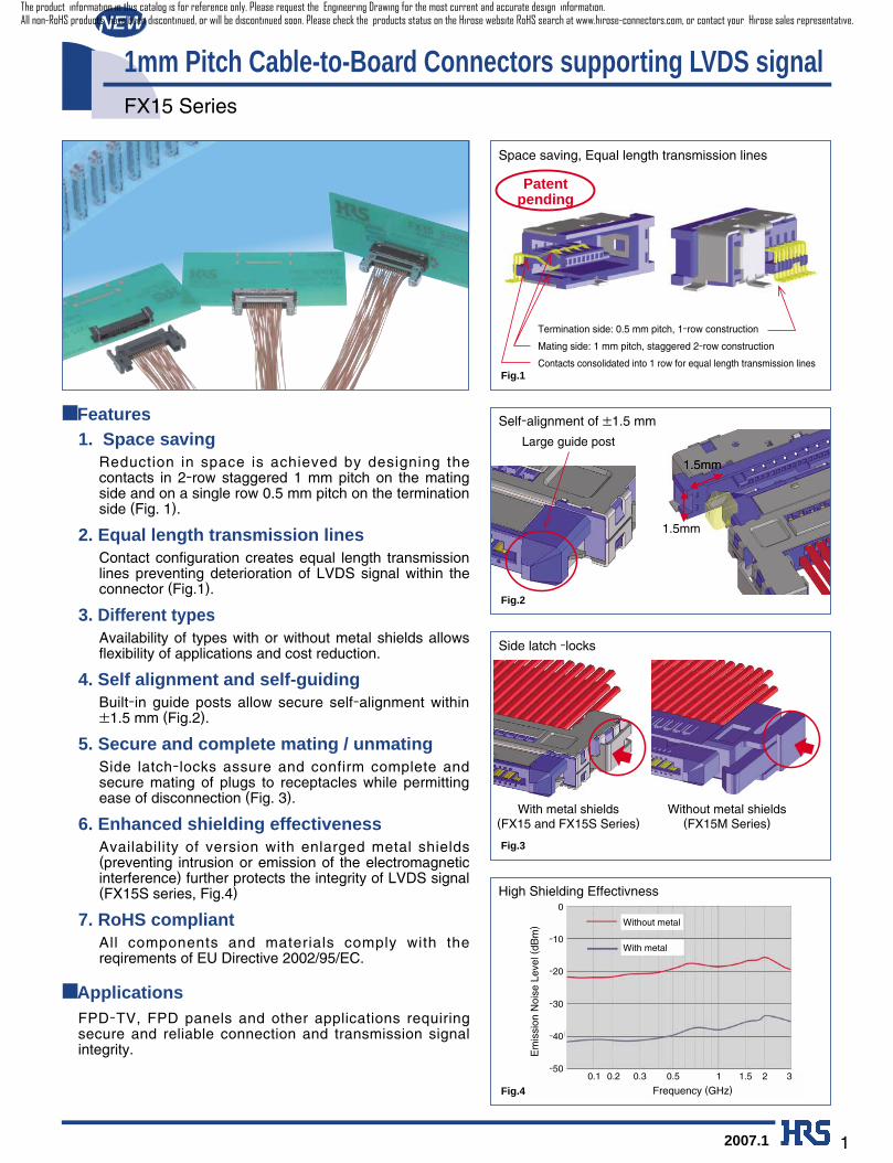
1mm Pitch Cable-to-Board Connectors supporting LVDS signalFX15 Series
2007.1
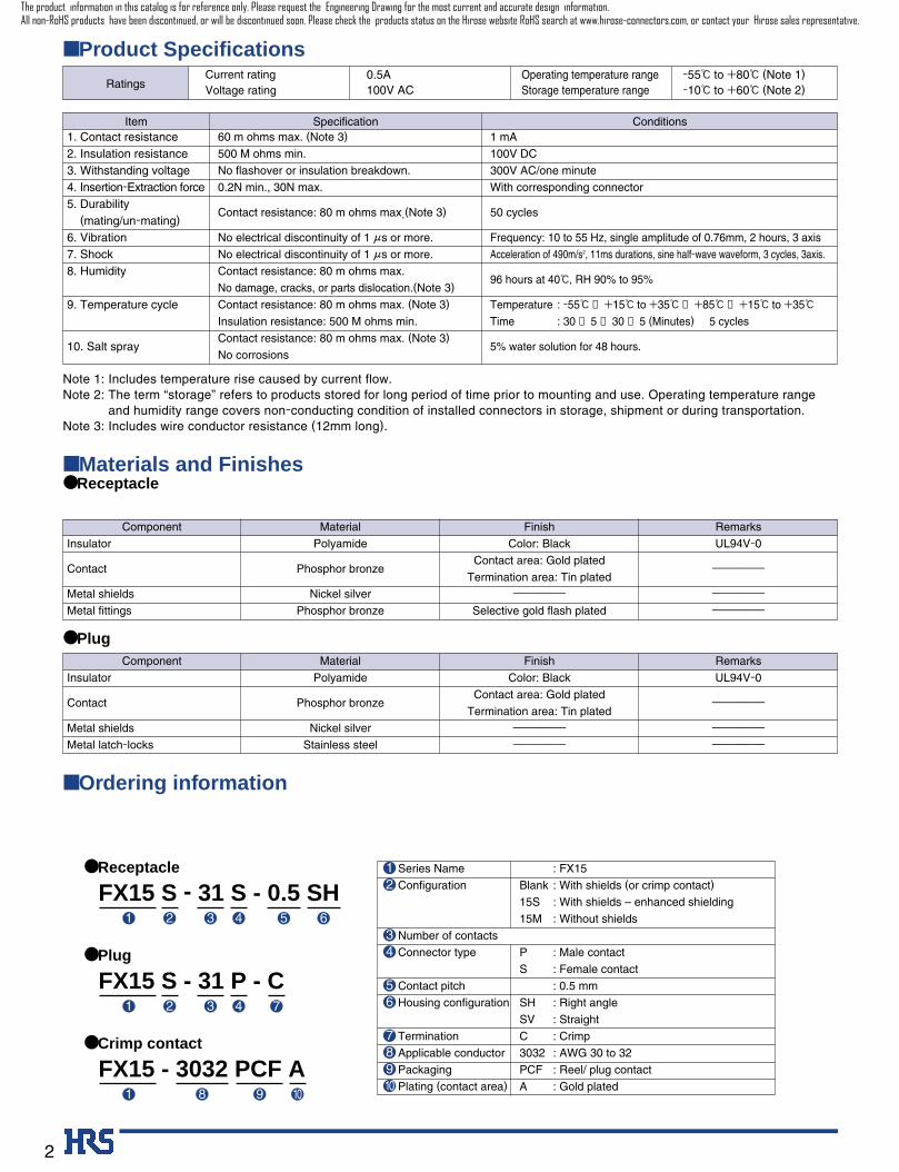
Contacts consolidated into 1 row for equal length transmission lines
Mating side: 1 mm pitch, staggered 2-row construction
Termination side: 0.5 mm pitch, 1-row construction
■ Features 1. Space saving
Reduction in space is achieved by designing thecontacts in 2-row staggered 1 mm pitch on the matingside and on a single row 0.5 mm pitch on the terminationside (Fig. 1).
2. Equal length transmission lines Contact configuration creates equal length transmissionlines preventing deterioration of LVDS signal within theconnector (Fig.1).
3. Different types Availability of types with or without metal shields allowsflexibility of applications and cost reduction.
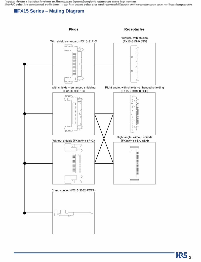
4. Self alignment and self-guiding Built-in guide posts allow secure self-alignment within±1.5 mm (Fig.2).
5. Secure and complete mating / unmating Side latch-locks assure and confirm complete andsecure mating of plugs to receptacles while permittingease of disconnection (Fig. 3).
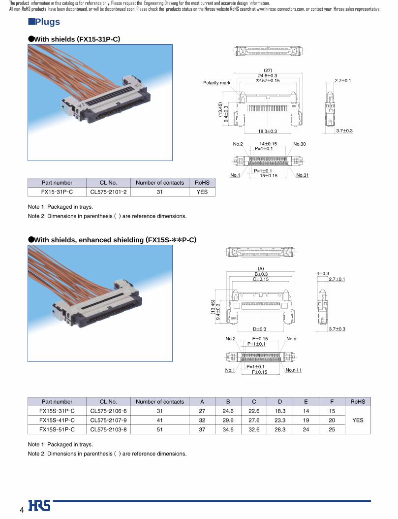
6. Enhanced shielding effectiveness Availability of version with enlarged metal shields(preventing intrusion or emission of the electromagneticinterference) further protects the integrity of LVDS signal(FX15S series, Fig.4)
7. RoHS compliant All components and materials comply with thereqirements of EU Directive 2002/95/EC.
■ ApplicationsFPD-TV, FPD panels and other applications requiringsecure and reliable connection and transmission signalintegrity.
Space saving, Equal length transmission lines
Self-alignment of ±1.5 mm
Side latch -locks
q
w
Patentpending
Large guide post
1.5mm1.5mm
1.5mm
With metal shields (FX15 and FX15S Series)
Without metal shields (FX15M Series)
q
w
0
0.1 0.2 0.3 0.5 1 2 31.5
-10
-20
-30
-40
-50
Frequency (GHz)
With metal
Without metal
Em
issi
on N
oise
Lev
el (
dBm
)
NEW
High Shielding Effectivness
Fig.1
Fig.2
Fig.3
Fig.4
The product information in this catalog is for reference only. Please request the Engineering Drawing for the most current and accurate design information.All non-RoHS products have been discontinued, or will be discontinued soon. Please check the products status on the Hirose website RoHS search at www.hirose-connectors.com, or contact your Hirose sales representative.
1 mA
100V DC
300V AC/one minute
With corresponding connector
50 cycles
Frequency: 10 to 55 Hz, single amplitude of 0.76mm, 2 hours, 3 axis
Acceleration of 490m/s2, 11ms durations, sine half-wave waveform, 3 cycles, 3axis.
96 hours at 40ç, RH 90% to 95%
Temperature : -55ç → +15ç to +35ç →+85ç →+15ç to +35ç
Time : 30 →5 →30 →5 (Minutes) 5 cycles
5% water solution for 48 hours.
2
60 m ohms max. (Note 3)
500 M ohms min.
No flashover or insulation breakdown.
0.2N min., 30N max.
Contact resistance: 80 m ohms max.(Note 3)
No electrical discontinuity of 1 µs or more.
No electrical discontinuity of 1 µs or more.
Contact resistance: 80 m ohms max.
No damage, cracks, or parts dislocation.(Note 3)
Contact resistance: 80 m ohms max. (Note 3)
Insulation resistance: 500 M ohms min.
Contact resistance: 80 m ohms max. (Note 3)
No corrosions
■ Materials and Finishes
■ Ordering information
UL94V-0
---------------
---------------
---------------
Material Finish RemarksComponent
Insulator
Contact
Metal shields
Metal fittings
Polyamide
Phosphor bronze
Nickel silver
Phosphor bronze
Color: Black
Contact area: Gold plated
Termination area: Tin plated
---------------
Selective gold flash plated
■ Product Specifications
RatingsCurrent ratingVoltage rating
0.5A100V AC
Operating temperature range Storage temperature range
-55ç to +80ç (Note 1) -10ç to +60ç (Note 2)
1. Contact resistance2. Insulation resistance3. Withstanding voltage4. Insertion-Extraction force5. Durability
(mating/un-mating)6. Vibration7. Shock8. Humidity
9. Temperature cycle
10. Salt spray
Item Specification Conditions
Note 1: Includes temperature rise caused by current flow.Note 2: The term “storage” refers to products stored for long period of time prior to mounting and use. Operating temperature range
and humidity range covers non-conducting condition of installed connectors in storage, shipment or during transportation.Note 3: Includes wire conductor resistance (12mm long).
● Receptacle
UL94V-0
---------------
---------------
---------------
Material Finish RemarksComponent
Insulator
Contact
Metal shields
Metal latch-locks
Polyamide
Phosphor bronze
Nickel silver
Stainless steel
Color: Black
Contact area: Gold plated
Termination area: Tin plated
---------------
---------------
● Plug
FX15 S - 31 S - 0.5 SH 1 632 4 5
● Receptacle
FX15 S - 31 P - C1 32 4 7
● Plug
FX15 - 3032 PCF A1 2 98 10
● Crimp contact
12
34
56
78910
Series Name
Configuration
Number of contacts
Connector type
Contact pitch
Housing configuration
Termination
Applicable conductor
Packaging
Plating (contact area)
: FX15
Blank : With shields (or crimp contact)
15S : With shields – enhanced shielding
15M : Without shields
P : Male contact
S : Female contact
: 0.5 mm
SH : Right angle
SV : Straight
C : Crimp
3032 : AWG 30 to 32
PCF : Reel/ plug contact
A : Gold plated
The product information in this catalog is for reference only. Please request the Engineering Drawing for the most current and accurate design information.All non-RoHS products have been discontinued, or will be discontinued soon. Please check the products status on the Hirose website RoHS search at www.hirose-connectors.com, or contact your Hirose sales representative.
3
■ FX15 Series – Mating Diagram
Plugs Receptacles
With shields – enhanced shielding(FX15S-**P-C)
Right angle, with shields –enhanced shielding(FX15S-**S-0.5SH)
Without shields (FX15M-**P-C)Right angle, without shields
(FX15M-**S-0.5SH)
Crimp contact (FX15-3032-PCFA)
With shields-standard- FX15-31P-CVertical, with shields(FX15-31S-0.5SV)
The product information in this catalog is for reference only. Please request the Engineering Drawing for the most current and accurate design information.All non-RoHS products have been discontinued, or will be discontinued soon. Please check the products status on the Hirose website RoHS search at www.hirose-connectors.com, or contact your Hirose sales representative.
4
■ Plugs
No.2
No.1
No.30
No.31
Polarity mark 22.57±0.15
(27)
9.4±
0.3
18.3±0.3
(13.
45)
P=1±0.114±0.15
P=1±0.115±0.15
24.6±0.32.7±0.1
3.7±0.3
Part number
FX15S-31P-C
FX15S-41P-C
FX15S-51P-C
CL575-2106-6
CL575-2107-9
CL575-2103-8
31
41
51
27
32
37
24.6
29.6
34.6
22.6
27.6
32.6
18.3
23.3
28.3
14
19
24
15
20
25
YES
CL No. Number of contacts A RoHS
YES
RoHS
FEDCB
● With shields (FX15-31P-C)
3.7±0.3
4±0.3B±0.3(A)
9.4±
0.3
D±0.3
C±0.15
(13.
45)
2.7±0.1
E±0.15P=1±0.1
P=1±0.1F±0.15No.1
No.2 No.n
No.n+1
● With shields, enhanced shielding (FX15S-**P-C)
Note 1: Packaged in trays.
Note 2: Dimensions in parenthesis ( ) are reference dimensions.
Note 1: Packaged in trays.
Note 2: Dimensions in parenthesis ( ) are reference dimensions.
Part number
FX15-31P-C CL575-2101-2 31
CL No. Number of contacts
The product information in this catalog is for reference only. Please request the Engineering Drawing for the most current and accurate design information.All non-RoHS products have been discontinued, or will be discontinued soon. Please check the products status on the Hirose website RoHS search at www.hirose-connectors.com, or contact your Hirose sales representative.
5
C±0.3
F±0.15P=1±0.1
P=1±0.1E±0.15
No.1 No.n+1
No.2 No.n
B±0.3
9.55
±0.
3
(A)
(D)
(13)
(13.
6)
4.2±0.3
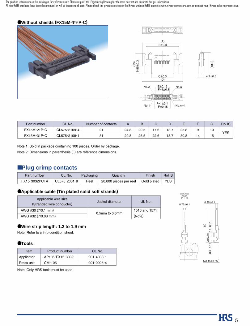
● Without shields (FX15M-**P-C)
Part number
FX15M-21P-C
FX15M-31P-C
CL575-2109-4
CL575-2108-1
21
31
24.8
29.8
CL No. Number of contacts A B
17.6
22.6
C
13.7
18.7
D
25.8
30.8
E
9
14
F
10
15
G
YES
RoHS
■ Plug crimp contacts CL No.Part number Packaging Quantity Finish RoHS
CL575-2001-8FX15-3032PCFA Reel 20,000 pieces per reel Gold plated YES
Applicable wire size
(Stranded wire conductor) Jacket diameter UL No.
AWG #30 (7/0.1 mm)
AWG #32 (7/0.08 mm) 0.5mm to 0.6mm
1516 and 1571
(Note)
Product number Item CL No.
AP105-FX15-3032
CM-105
Applicator
Press unit
901-4033-1
901-0005-4
0.5±
0.15
0.9±
0.15
0.72±0.1(7
) 2±
0.15
0.35±0.1
t=0.15±0.05
Note: Only HRS tools must be used.
Note: Refer to crimp condition sheet.
● Applicable cable (Tin plated solid soft strands)
● Tools
● Wire strip length: 1.2 to 1.9 mm
20.5
25.5
Note 1: Sold in package containing 100 pieces. Order by package.
Note 2: Dimensions in parenthesis ( ) are reference dimensions.
The product information in this catalog is for reference only. Please request the Engineering Drawing for the most current and accurate design information.All non-RoHS products have been discontinued, or will be discontinued soon. Please check the products status on the Hirose website RoHS search at www.hirose-connectors.com, or contact your Hirose sales representative.
6
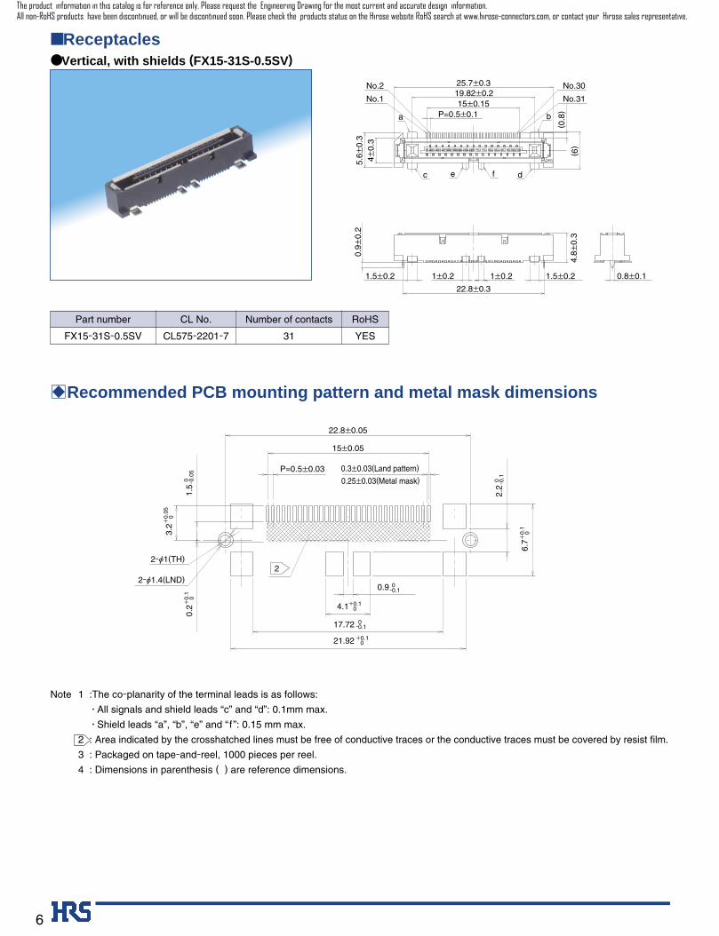
No.1
No.2
No.31
No.30
a b
c de f
P=0.5±0.115±0.15
19.82±0.225.7±0.3
4±0.
35.
6±0.
3
(6)
(0.8
)
0.9±
0.2
22.8±0.3
4.8±
0.3
1.5±0.2 1±0.2 1±0.2 1.5±0.2 0.8±0.1
■ Receptacles● Vertical, with shields (FX15-31S-0.5SV)
2
1.5
0 -0.0
5
3.2
+0.
05 0
2-Ø1(TH)
2-Ø1.4(LND)0.9 0
-0.1
4.1+0.1 0
17.72 0-0.1
21.92 +0.1 0
2.2
0 -0.1
6.7
+0.
1 0
22.8±0.05
15±0.05
P=0.5±0.03 0.3±0.03(Land pattern)
0.25±0.03(Metal mask)
0.2
+0.
1 0
Note 1 :The co-planarity of the terminal leads is as follows:
• All signals and shield leads “c” and “d”: 0.1mm max.
• Shield leads “a”, “b”, “e” and “ f ”: 0.15 mm max.
2 : Area indicated by the crosshatched lines must be free of conductive traces or the conductive traces must be covered by resist film.
3 : Packaged on tape-and-reel, 1000 pieces per reel.
4 : Dimensions in parenthesis ( ) are reference dimensions.
BRecommended PCB mounting pattern and metal mask dimensions
YES
RoHSPart number
FX15-31S-0.5SV CL575-2201-7 31
CL No. Number of contacts
The product information in this catalog is for reference only. Please request the Engineering Drawing for the most current and accurate design information.All non-RoHS products have been discontinued, or will be discontinued soon. Please check the products status on the Hirose website RoHS search at www.hirose-connectors.com, or contact your Hirose sales representative.
7
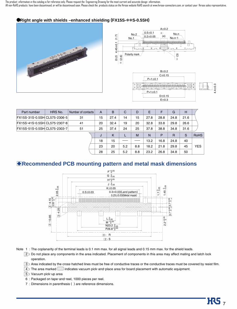
4.45
±0.
1
(3)
(0.2
) (1
.7) 0.5±0.1
A±0.2
P=1±0.1
P=1±0.1
C±0.15
D±0.15
B±0.2
E±0.3
0.2±0.05No.1
No.2 No.n
No.n-1
(2.6
)
(4)
Polarity mark
4.4±
0.3
4
5
4
● Right angle with shields –enhanced shielding (FX15S-**S-0.5SH)
2
2
2
3
3
L 0-0.05
4.25
4.15
K±0.050.5±0.03
0.25±0.03(Metal mask)
J 0-0.05
H+0.05 0
G 0-0.05
F+0.05 0
3.55
+0.
05 0
2.05
0 -0.0
5
M +0.05 0
N23.2 0-0.05
P26.8+0.05 0
3.7+
0.05
0
1.45
0 -0.0
52.
2+
0.05
0
1.7
0 -0.0
5
3.7+
0.05
0
R
13.8
5
S
0.3±0.03(Land pattern)
Note 1 : The coplanarity of the terminal leads is 0.1 mm max. for all signal leads and 0.15 mm max. for the shield leads.
2 : Do not place any components in the area indicated. Placement of components in this area may affect mating and latch lock
operation.
3 : Area indicated by the cross-hatched lines must be free of conductive traces or the conductive traces must be covered by resist film.
4 : The area marked indicates vacuum pick-and-place area for board placement with automatic equipment.
5 : Vacuum pick-up area
6 : Packaged on tape-and-reel, 1000 pieces per reel.
7 : Dimensions in parenthesis ( ) are reference dimensions.
BRecommended PCB mounting pattern and metal mask dimensions
Part number
FX15S-31S-0.5SH
FX15S-41S-0.5SH
FX15S-51S-0.5SH
CL575-2306-5
CL575-2307-8
CL575-2303-7
31
41
51
15
20
25
HRS No. Number of contacts A B
14
19
24
C
15
20
25
D
27.8
32.8
37.8
E
28.8
33.8
38.8
F
24.8
29.8
34.8
G
21.6
26.6
31.6
H
27.4
32.4
37.4
18
23
28
J K
------
5.2
5.2
L
------
8.8
8.8
M
13.2
18.2
23.2
N
16.8
21.8
26.8
P
24.8
29.8
34.8
R
40
45
50
YES
S RoHS
15
20
25
The product information in this catalog is for reference only. Please request the Engineering Drawing for the most current and accurate design information.All non-RoHS products have been discontinued, or will be discontinued soon. Please check the products status on the Hirose website RoHS search at www.hirose-connectors.com, or contact your Hirose sales representative.
8
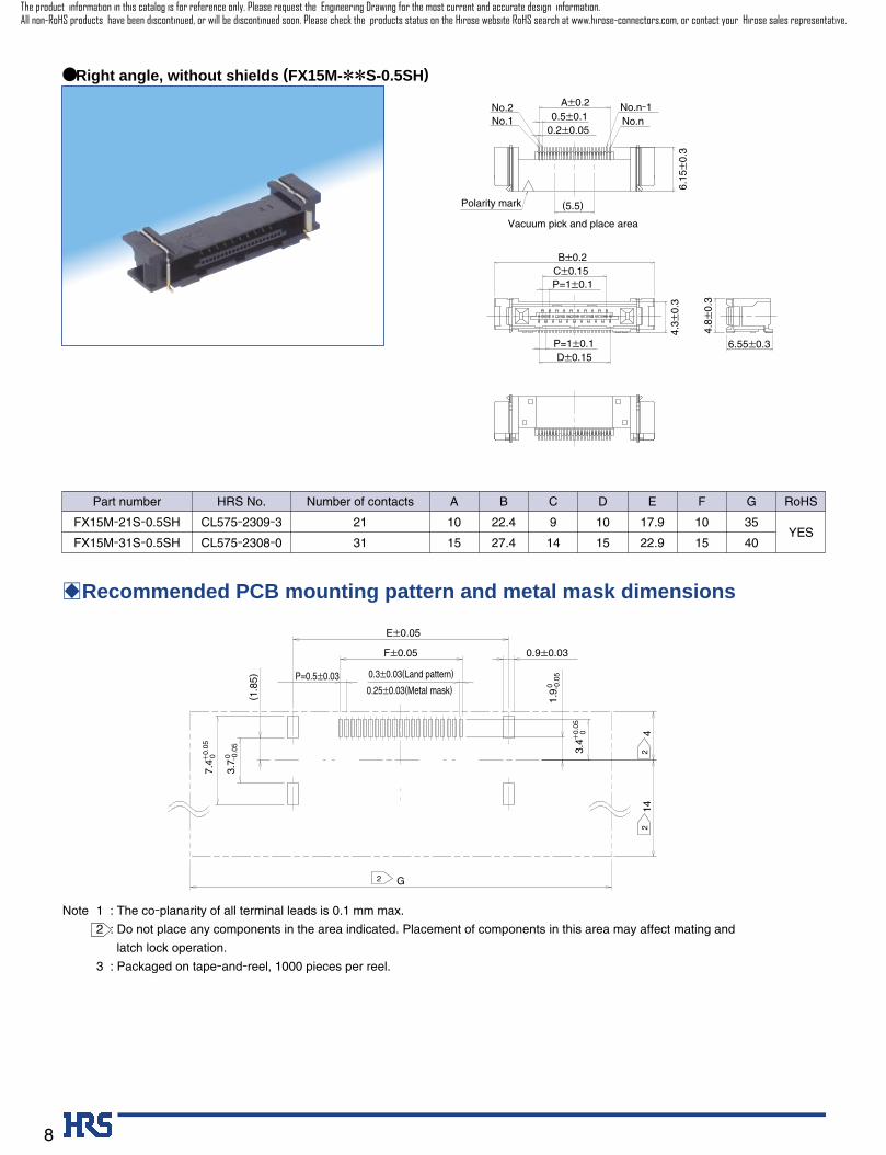
4.3±
0.3
4.8±
0.3
(5.5)
Vacuum pick and place area
Polarity mark
No.1No.2
No.nNo.n-1
6.55±0.3
B±0.2
D±0.15
P=1±0.1
P=1±0.1
C±0.15
A±0.20.5±0.1
0.2±0.05
6.15
±0.
3
● Right angle, without shields (FX15M-**S-0.5SH)
E±0.05
0.3±0.03(Land pattern)
0.9±0.03
3.7 0 -0
.05
7.4+
0.05
0
(1.8
5)
0.25±0.03(Metal mask)
4
G
142
F±0.05
P=0.5±0.03
1.9 0 -0
.05
3.4+
0.05
0
2
2
Part number
FX15M-21S-0.5SH
FX15M-31S-0.5SH
CL575-2309-3
CL575-2308-0
21
31
10
15
HRS No. Number of contacts A B
9
14
C
10
15
D
17.9
22.9
E
10
15
F
35
40
G
YES
RoHS
22.4
27.4
Note 1 : The co-planarity of all terminal leads is 0.1 mm max.
2 : Do not place any components in the area indicated. Placement of components in this area may affect mating and
latch lock operation.
3 : Packaged on tape-and-reel, 1000 pieces per reel.
BRecommended PCB mounting pattern and metal mask dimensions
The product information in this catalog is for reference only. Please request the Engineering Drawing for the most current and accurate design information.All non-RoHS products have been discontinued, or will be discontinued soon. Please check the products status on the Hirose website RoHS search at www.hirose-connectors.com, or contact your Hirose sales representative.
9
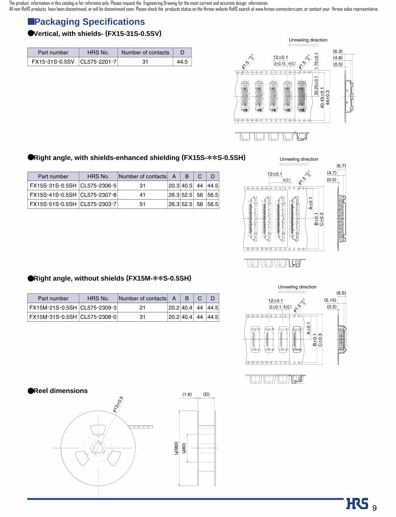
■ Packaging Specifications● Vertical, with shields- (FX15-31S-0.5SV)
● Right angle, with shields-enhanced shielding (FX15S-**S-0.5SH)
● Right angle, without shields (FX15M-**S-0.5SH)
● Reel dimensions
A A A A A
(4.8) (0.5)
(6.3)
Unreeling direction
40.4
5±0.
144
±0.
320.2
5±0.
11.
75±
0.1
Ø1.5
+0.
1 0
Ø1.5
+0.
1 0
4±0.12±0.1512±0.1
A±
0.1
B±
0.1
C±
0.3
Ø1.5
+0.1
0
4±0.112±0.1
(0.5)
(4.7)
(6.7) Unreeling direction
A±
0.1
B±
0.1
C±
0.3
Ø1.5
+0.1
04±0.12±0.1
12±0.1(0.5)
(5.15)
(6.5) Unreeling direction
Ø13±
0.5
(1.6)
(Ø38
0)
(Ø80
)
(D)
Part number
FX15S-31S-0.5SH
FX15S-41S-0.5SH
FX15S-51S-0.5SH
CL575-2306-5
CL575-2307-8
CL575-2303-7
31
41
51
20.3
26.3
26.3
HRS No. Number of contacts A
40.5
52.5
52.5
B
44
56
56
C
44.5
56.5
56.5
D
Part number
FX15M-21S-0.5SH
FX15M-31S-0.5SH
CL575-2309-3
CL575-2308-0
21
31
20.2
20.2
HRS No. Number of contacts A
40.4
40.4
B
44
44
C
44.5
44.5
D
Part number
FX15-31S-0.5SV CL575-2201-7 31
HRS No. Number of contacts
44.5
D
The product information in this catalog is for reference only. Please request the Engineering Drawing for the most current and accurate design information.All non-RoHS products have been discontinued, or will be discontinued soon. Please check the products status on the Hirose website RoHS search at www.hirose-connectors.com, or contact your Hirose sales representative.
10
250
150ç
180ç
30±10sec.90±30sec.
230ç
MAX 250ç
Time (sec.)
Sodering(230çmin)
Preheating(150 to 180ç)
230
180
25
150
0
100
Te
mp
era
ture
(ç
)
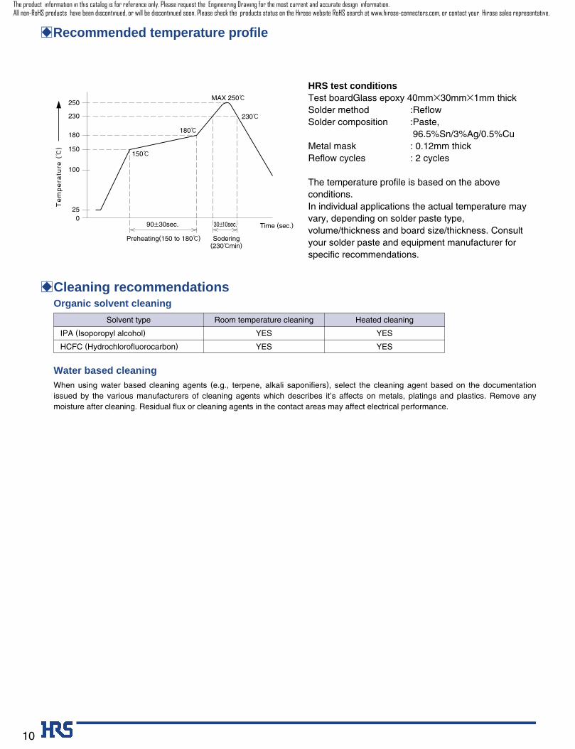
BRecommended temperature profile
HRS test conditionsTest boardGlass epoxy 40mm∞30mm∞1mm thickSolder method :ReflowSolder composition :Paste,
96.5%Sn/3%Ag/0.5%CuMetal mask : 0.12mm thickReflow cycles : 2 cycles
The temperature profile is based on the aboveconditions.In individual applications the actual temperature mayvary, depending on solder paste type,volume/thickness and board size/thickness. Consultyour solder paste and equipment manufacturer forspecific recommendations.
BCleaning recommendations
Water based cleaningWhen using water based cleaning agents (e.g., terpene, alkali saponifiers), select the cleaning agent based on the documentationissued by the various manufacturers of cleaning agents which describes it’s affects on metals, platings and plastics. Remove anymoisture after cleaning. Residual flux or cleaning agents in the contact areas may affect electrical performance.
Organic solvent cleaning
Solvent type Room temperature cleaning Heated cleaning
IPA (Isoporopyl alcohol)
HCFC (Hydrochlorofluorocarbon)
YES
YES
YES
YES
The product information in this catalog is for reference only. Please request the Engineering Drawing for the most current and accurate design information.All non-RoHS products have been discontinued, or will be discontinued soon. Please check the products status on the Hirose website RoHS search at www.hirose-connectors.com, or contact your Hirose sales representative.
11
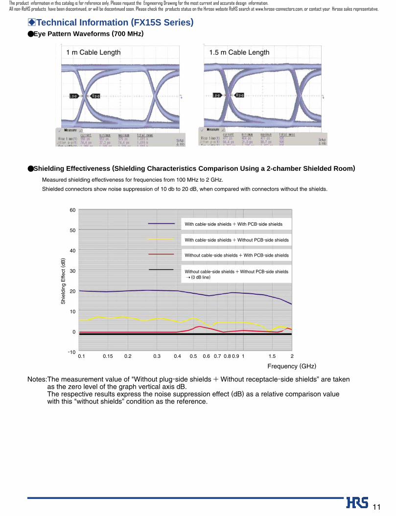
BTechnical Information (FX15S Series)● Eye Pattern Waveforms (700 MHz)
● Shielding Effectiveness (Shielding Characteristics Comparison Using a 2-chamber Shielded Room)
Notes:The measurement value of "Without plug-side shields + Without receptacle-side shields” are takenas the zero level of the graph vertical axis dB.The respective results express the noise suppression effect (dB) as a relative comparison valuewith this "without shields” condition as the reference.
With cable-side shields + With PCB-side shields
With cable-side shields + Without PCB-side shields
Without cable-side shields + With PCB-side shields
Without cable-side shields + Without PCB-side shields ➝ (0 dB line)
60
50
40
30
20
10
0
-100.1 0.15 0.2 0.3 0.4 0.5 0.6 0.7 0.8 0.9 1 1.5 2
Frequency (GHz)
Shi
eldi
ng E
ffect
(dB
)
Measured shielding effectiveness for frequencies from 100 MHz to 2 GHz.
Shielded connectors show noise suppression of 10 db to 20 dB, when compared with connectors without the shields.
1 m Cable Length 1.5 m Cable Length
The product information in this catalog is for reference only. Please request the Engineering Drawing for the most current and accurate design information.All non-RoHS products have been discontinued, or will be discontinued soon. Please check the products status on the Hirose website RoHS search at www.hirose-connectors.com, or contact your Hirose sales representative.
12
Precautions and recommendations
Retention tab
Crimp side
Molded-in lance
Molded-in lance
Molded-in lance Retention tab facing down
Retention tab facing up
Retention tab
1
2
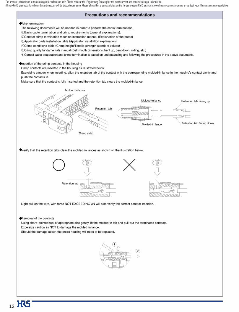
◆ Wire termination
The following documents will be needed in order to perform the cable terminations.
1Basic cable termination and crimp requirements (general explanations).
2Contact crimp termination machine instruction manual (Explanation of the press)
3Applicator parts installation table (Applicator installation explanation)
4Crimp conditions table (Crimp height/Tensile strength standard values)
5Crimp quality fundamentals manual (Bell-mouth dimensions, bent up, bent down, rolling, etc.)
* Correct cable preparation and crimp termination is based on understanding and following the procedures in the above documents.
◆ Insertion of the crimp contacts in the housing
Crimp contacts are inserted in the housing as illustrated below.
Exercising caution when inserting, align the retention tab of the contact with the corresponding molded-in lance in the housing’s contact cavity and
push the contacts in.
Make sure that the contact is fully inserted and the retention tab clears the molded-in lance.
◆ Verify that the retention tabs clear the molded-in lances as shown on the illustration below.
Light pull on the wire, with force NOT EXCEEDING 3N will also verify the correct contact insertion.
◆ Removal of the contacts
Using sharp-pointed tool of appropriate size gently lift the molded-in tab and pull-out the terminated contacts.
Excersize caution as NOT to damage the molded-in lance.
Should the damage occur, the entire housing will need to be replaced.
The product information in this catalog is for reference only. Please request the Engineering Drawing for the most current and accurate design information.All non-RoHS products have been discontinued, or will be discontinued soon. Please check the products status on the Hirose website RoHS search at www.hirose-connectors.com, or contact your Hirose sales representative.
13
Precautions and recommendations
Connectors
Packaging
Triangle mark
MatingMating
Arrow mark
Triangle mark
Center mark Center mark
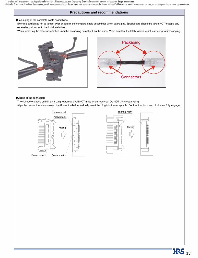
◆ Packaging of the complete cable assemblies
Exercise caution as not to tangle, twist or deform the complete cable assemblies when packaging. Special care should be taken NOT to apply any
excessive pull forces to the individual wires.
When removing the cable assemblies from the packaging do not pull on the wires. Make sure that the latch-locks are not interfering with packaging.
◆ Mating of the connectors
The connectors have built-in polarizing feature and will NOT mate when reversed. Do NOT try forced mating.
Align the connectors as shown on the illustration below and fully insert the plug into the receptacle. Confirm that both latch-locks are fully engaged.
The product information in this catalog is for reference only. Please request the Engineering Drawing for the most current and accurate design information.All non-RoHS products have been discontinued, or will be discontinued soon. Please check the products status on the Hirose website RoHS search at www.hirose-connectors.com, or contact your Hirose sales representative.
14
Precautions and recommendations
B
B
B
2Pull straight apart
1Press
1Press
1Press
1Press
B
B
Lock latches
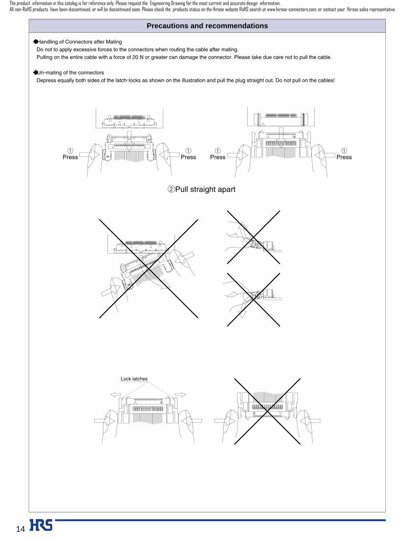
◆ Handling of Connectors after Mating
Do not to apply excessive forces to the connectors when routing the cable after mating.
Pulling on the entire cable with a force of 20 N or greater can damage the connector. Please take due care not to pull the cable.
◆ Un-mating of the connectors
Depress equally both sides of the latch-locks as shown on the illustration and pull the plug straight out. Do not pull on the cables!
The product information in this catalog is for reference only. Please request the Engineering Drawing for the most current and accurate design information.All non-RoHS products have been discontinued, or will be discontinued soon. Please check the products status on the Hirose website RoHS search at www.hirose-connectors.com, or contact your Hirose sales representative.
15
Soldering area 1
Soldering area 2
(Ground harness examples)
B B
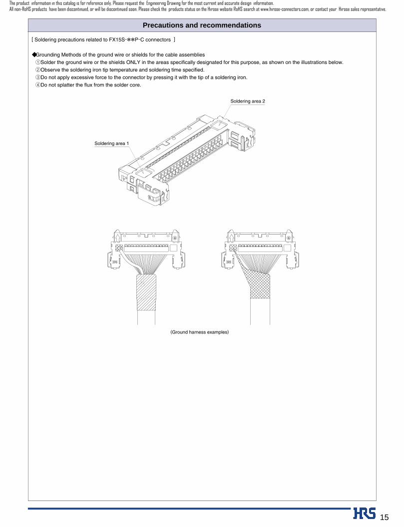
[ Soldering precautions related to FX15S-**P-C connectors ]
◆ Grounding Methods of the ground wire or shields for the cable assemblies
1Solder the ground wire or the shields ONLY in the areas specifically designated for this purpose, as shown on the illustrations below.
2Observe the soldering iron tip temperature and soldering time specified.
3Do not apply excessive force to the connector by pressing it with the tip of a soldering iron.
4Do not splatter the flux from the solder core.
Precautions and recommendations
The product information in this catalog is for reference only. Please request the Engineering Drawing for the most current and accurate design information.All non-RoHS products have been discontinued, or will be discontinued soon. Please check the products status on the Hirose website RoHS search at www.hirose-connectors.com, or contact your Hirose sales representative.