newsletter may 2016 -...
TRANSCRIPT

Page 1 of 39
Newsletter – May 2016
Contents 1. Chairman’s News ...................................................................................................................... 2
2. Chasing Steam trains in Europe. .............................................................................................. 5
3. Locomotives, Engines and Trains seen on my Model Railway ............................................... 11
4. Silent no More. ....................................................................................................................... 17
5. The EMRIG Water Tower Challenge. ...................................................................................... 31
6. Upcoming Duty Roster ........................................................................................................... 38
7. Club Diary:- ............................................................................................................................. 38
8. Club Contact details:- ............................................................................................................. 39
9. Club Banking Details:- ............................................................................................................ 39

Page 2 of 39
Chairman’s News
By Colin Tanner-Tremaine
The past Month has been good for me and EMRIG, but unfortunately some
not so good news as well. My holiday at the Blue Marlin in Scottburgh was
great, good weather, great food, warm sea but best of all no model railways,
no soldering iron, decoder issues and no calls for help from you the
members or anyone else; a true holiday, thank you.
A few weeks ago a young lady from FMC Corporation phoned me to ask if
we were interested in a box of old toy train stuff that they had lying around
in the office store. If not then they would throw it away, so I asked her to
bring it in to the club so that I could assess the contents on Saturday 7th which she duly did. WOW,
this Typek A4 printer paper box contained 36 brand new never been opened boxes of ATLAS Train-
Man N gauge covered hopper wagons, all branded FMC Chemicals, and fitted with buck-eye Kadee
type couplers. What a unit train these will make. Also in this box were 4 HO similar wagons which
will join the American club train. Now how lucky can one get, many thanks to the young ladies
thoughtfulness, she could have just chucked them in the bin but as she often comes into
Northmead Mall and knew of our presence a phone call to me and that was it. Now we must thank
FMC by some publicity and advertising of their company and products. This also demonstrates the
advantage of being in the public space in a shopping mall.
While on the subject of Northmead Mall all is well, their Marketing Company are keen for us to
stay in the Mall and would like us to put a layout in the centre Mall. A good idea but impractical so
as an alternative I am considering offering to put up our 2 Exhibition layouts between Maxis and
Jam stores for a weekend. This type of event is what they were designed for, easy to transport,

Page 3 of 39
erect and operate. So your comments please, the date not yet decided.
Back to the N gauge layout, I am glad to see considerable progress with the along the wall layout,
thanks to Ron Poole and his team. The new FMC unit train is a real motivating spur to get it
completed and operational. I intend to invite the seniors from FMC to come and see “their” train in
operation. It has also been requested that we obtain a radio/infra-red receiver unit that will enable
operation of the trains “wirelessly” not needing any tethering. Unfortunately for us the model that
some members have is now obsolete and out of production and the replacement receiver will cost
approximately R3500! This model will not be compatible with the throttles that we have so that
option is out. We will have to stay with the infra-red UR90 which is quite adequate and can be used
by all members’ throttles. The cost of this UR90 is less than R1000, so as we have the funds one
will be obtained and installed soon.
We still have not recovered the missing H & M Duette controller that has been removed from our
premises without any permission so the H0 exhibition layout is not operational until it is either
returned or a new one is obtained. Does anyone have a suitable replacement that can be offered
to the club? I have a single channel supply which I will install this coming Saturday; at least one
track will then be operational.
To police our premises and layouts to help deter the skelums is difficult and as we are open to the
public we will always be at risk from suffering losses and damage so I am investigating the
procurement and installation of a CCTV system. I am obtaining quotes from local suppliers, does
any member have contacts or suggestions, please let me know asap. I understand that the
hardware will only cost about R1200 to R1500, with installation extra. We can afford that, do you
agree to installing this system? A hard drive type storage and monitor VDU unit will be required
which can be interrogated by laptop at any time.
Back from holiday I was naturally keen to get down the club so on Wednesday while my wife went
off shopping I was at the club, watching a couple of trains in operation, good. One, a smart Eastern
Region passenger with a new Deltic locomotive on the front was quietly sitting at the platform
while the driver was having a chat to some visitors as he is want to do. Meanwhile there was this
fine model of a 2-10-2 Tank engine of the Deutsche Bahn running very nicely on the same track.
Now as the passenger train/station master had not protected the stationary passenger by setting
the points to the through line/centre road and the tank engine driver was not paying attention
either, guess what happened? An almighty rear ending occurred!! So what do we learn from this
incident?
1. If you are driving your train you must PAY ATTENTION to your train, the route and what
may be in front of you.

Page 4 of 39
2. When approaching a station request permission from the station master for a route, or
set it yourself if no station master or train controller is available.
3. When you stop in the station, usually on a platform or siding make sure that there is a
through route set for others to pass without crashing into you.
Remember that you are sharing the railway with other members so be aware of their trains and
respect their rights and property, do NOT go crashing into it.
Finally I have had complaints and requests regarding visitors. As we are open to the public we
stand not only the risk of damage and theft but also many questions from the visiting spectators.
Great, one of our missions is to sell and promote our hobby to the public especially the technically
minded younger generation. Now the complaint is based on how far we go in promoting the hobby.
Do we allow visitors to drive our trains on our layout? What happens if they damage the train,
controller or the accessories such as the turnouts/points. One visitor was caught trying the change
a point by forcing it by hand, strictly not allowed. If it was on my station I would “Blow a Fuse”.
Then who would be responsible to repair or replace the item?
So whilst wanting to promote our model trains and their many fancy features I put the limit on
demonstrating and NOT physically touching or driving on our layout. Now what about visitors from
other model railway clubs? Do we allow them to come and run their or our trains on our layouts?
Are they familiar with Digitrax and general operating rules? I have been allowed to run my Garratt
on another layout but they knew me well and likewise I knew them too, so trust and familiarity
allowed me that pleasure. So I am content to let well known members of other clubs to come and
enjoy our layout occasionally, after all they should know how to operate DCC model trains if they
own one. But they must be fully informed on our rules and operation of the points etc. For
instance KEEP TO THE RIGHT track, and best to leave the operation of the points to one of our
experienced members. All comments and suggestions welcomed.
Our next swap meet is being held on Saturday 28th May in the same place as last time so
remember we need trains running on ALL layouts, and helpers to set up the tables and assist the
traders in bringing their ware from car to table. Thanks in advance.
So that is enough from me for this month; keep well and enjoy your model trains and the
camaraderie with fellow members which to me, is the essence of being a club member.
Regards to all,
Colin TT.

Page 5 of 39
Chasing Steam trains in Europe.
By Jean Dulez
Ed: - This month Jean moves over to Europe with the start of a series of articles of his visits there. Originally, Jeans first article (this article) was 8 pages long! Now as a good editor (I hope) I have purposely cut it down to 4 to give “meat” to future editions. We don’t want to throw everything out to you early and then battle for content in the future. Jean, many many thanks for all these articles you do!
European Trip 2007 The origins of this latest venture out of South Africa are traced to the previous David Rodgers local
tour in May 2007. My linesiding companions were Peter Lemmey (UK) and Jean Francois Couëdou
(France) on this particular occasion.
Whilst discussing overseas events, one evening in Creighton during one of our stopovers, we
stumbled across a tour advertised to Chemnitz in the old East Germany for a steam festival. I had
heard of this annual steam up of a huge collection of standard gauge locomotives and had also re-
ceived information from a fellow HO enthusiast, Tony Elliot, who had visited this particular event
the previous year, in 2006.
At the time, Peter Lemmey said he would also be interested in visiting Chemnitz during August
when the festival was to take place; hence I started organising a trip to Europe commencing in
Germany in late August. The trip would also see me visiting Switzerland, the UK and France. Part of
the three week tour would include visits to three of my employer's group corporate engineering
plants in some of these countries, as well as looking up family and friends in the UK and France.
Whilst discussing the tour, I proceeded to make flight arrangements that would eventually include
six countries over the three weeks, quite a packed schedule.
The best deal I could get was to fly SAA to Frankfurt and then change to an internal flight to Berlin.
Thereafter, I would meet up with Peter, who would have flown in directly from London.
We would then rent a vehicle and drive down to Chemnitz in the south, situated roughly midway
between Dresden and Leipzig in Saxony.
East Germany
Page 6 of 39
My trip got off to a bad start with overloading and other SAA problems, this saw me rerouted to
London, then onto a BA flight to Berlin. As chance would have it, while changing planes, I bumped
into Peter himself at Heathrow Terminal One. It turned out that we were now conveniently
booked on the same flight.
This did not get off well either, with a two hour delay (whilst we sat in the plane) due to a wheel
oil seal leak. Our eventual Berlin arrival was well behind schedule. Next, to add to our troubles,
one of my bags had been left behind during transfer at Heathrow, so we decided to wait fcr the
next BA flight on which it had subsequently been forwarded. This plane was now only two hours
behind our own flight.
All this only saw us make it onto the autobahn at 4pm and thus arrive at Chemnitz around 6:30pm,
too late for any of the Saturday's activities. The centre of Chemnitz (formerly called Karl Marx
Stadt) is being rejuvenated from its drab appearance dating from its previous communist era days.
After checking in to our hotel down town, we planned what to do next for the second day of the
festival, Sunday the 26th.
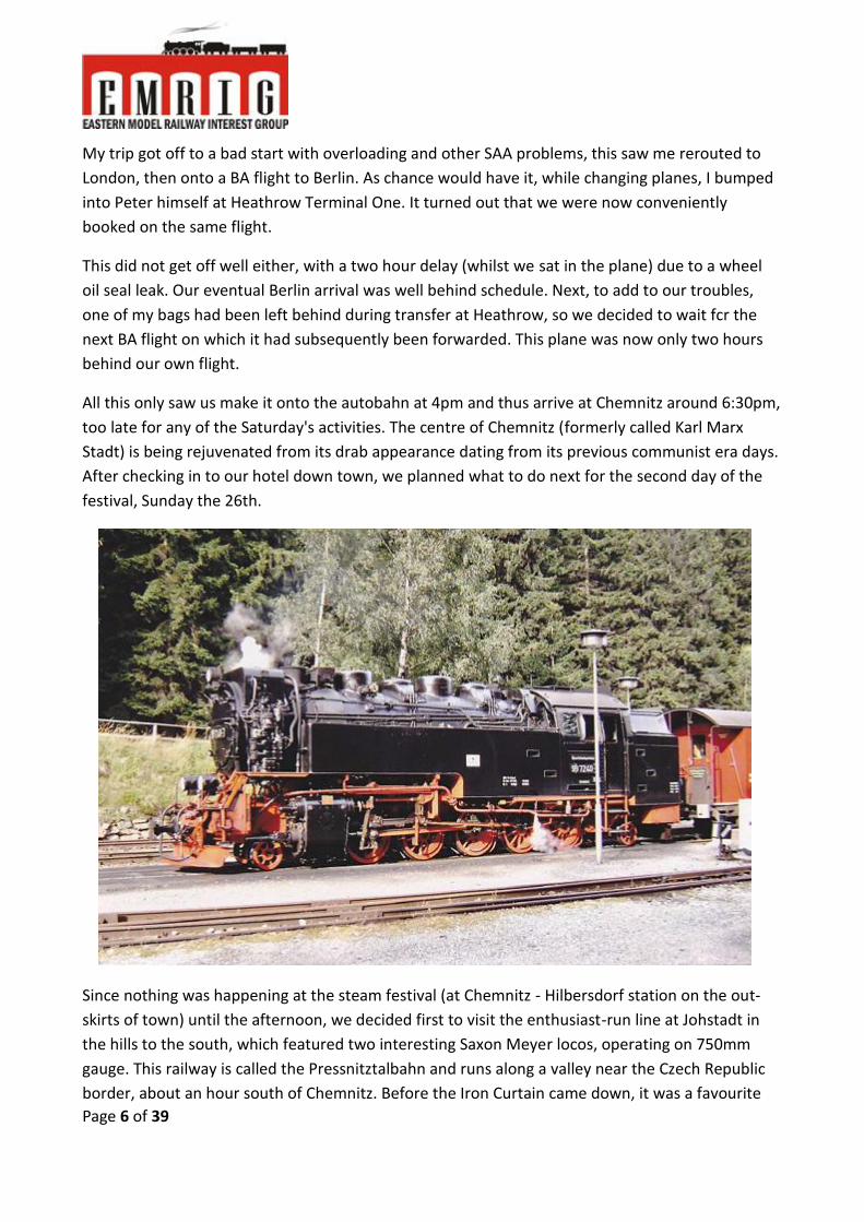
Since nothing was happening at the steam festival (at Chemnitz - Hilbersdorf station on the out-
skirts of town) until the afternoon, we decided first to visit the enthusiast-run line at Johstadt in
the hills to the south, which featured two interesting Saxon Meyer locos, operating on 750mm
gauge. This railway is called the Pressnitztalbahn and runs along a valley near the Czech Republic
border, about an hour south of Chemnitz. Before the Iron Curtain came down, it was a favourite
Page 7 of 39
line for visiting Western enthusiasts because of the picturesque rural scenery and the little fully-
articulated 0-4-0+0-4-0 Meyer tanks, a speciality of the old Saxon narrow gauge lines.
We managed to follow two up and down trains during the morning, before heading back to
Chemnitz. Peter said the line still retained the steamy atmosphere of his earlier visits in com-
munist days.
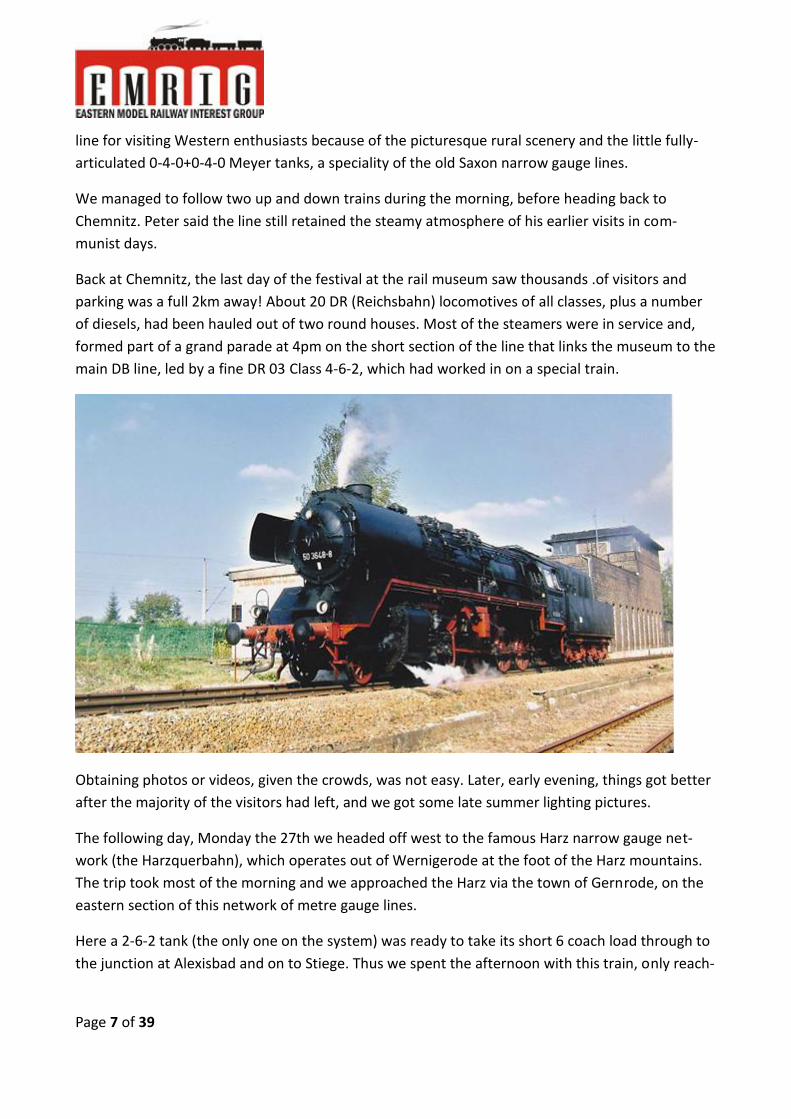
Back at Chemnitz, the last day of the festival at the rail museum saw thousands .of visitors and
parking was a full 2km away! About 20 DR (Reichsbahn) locomotives of all classes, plus a number
of diesels, had been hauled out of two round houses. Most of the steamers were in service and,
formed part of a grand parade at 4pm on the short section of the line that links the museum to the
main DB line, led by a fine DR 03 Class 4-6-2, which had worked in on a special train.
Obtaining photos or videos, given the crowds, was not easy. Later, early evening, things got better
after the majority of the visitors had left, and we got some late summer lighting pictures.
The following day, Monday the 27th we headed off west to the famous Harz narrow gauge net-
work (the Harzquerbahn), which operates out of Wernigerode at the foot of the Harz mountains.
The trip took most of the morning and we approached the Harz via the town of Gernrode, on the
eastern section of this network of metre gauge lines.
Here a 2-6-2 tank (the only one on the system) was ready to take its short 6 coach load through to
the junction at Alexisbad and on to Stiege. Thus we spent the afternoon with this train, only reach-

Page 8 of 39
ing Drei-Annen Hohne and the main part of the Hartz network quite late. However, some good
shots of the 2-6-2 tank climbing through wooded country were to be had.
Then down to Wernigerode, headquarters of the Harzquerbahn, after the last of the trains on the
system had already returned from the hills. Hence, a few photos at the depot in Wernigerode
were in order, before we checked into our hotel, a traditional inn in the historic town centre.
The whole of Tuesday the 28th and part of Wednesday were spent chasing the frequent trains
powered by the fleet of chunky 2-10-2 tanks from Wernigerode up to the junction at Drei-Annen
Hohne in the mountains. We were also fortunate also to get a run with a 0¬4-4-0 Mallet tank on a
vintage train today.
At Drei Annen Hohne a popular line, with frequent trains, branches off on a spiral climb through
the pine forests to the scenic mountain-top location at Brocken. The other branch to Nordhausen
sees only two steam trains each way, per day, during the peak tourist season in mid-summer.
To see the line to Brocken, one has to take the train, which we did on one occasion, since there is
no road access. The big 2-10-2 tanks handle the gradient with ease. The summit at the end of the

Page 9 of 39
line overlooks countryside that fell in the previous Western German sector and was thus a favour-
ite lookout post for the East German security. One would surmise that trips up here were restrict-
ed in that period, therefore.
On Wednesday afternoon we returned to Berlin Tegel Airport, where Peter and I parted ways,
since we were on different flights back to the UK.
We would meet up at the end of my tour, when we had planned a visit to the Mid Hants preserved
railway to the south west of London, in Hampshire
UK Visits
I spent a day in London on Thursday the 30th visiting relatives and thereafter set off by train to
Manchester. From there, I travelled north to a town called Todmorden, where our company, Weir
Minerals, has a big plant and foundry. In fact, it is the largest industrial operation in the area.
On Saturday the 1st of September, I had arranged to meet steam enthusiast, David Rodgers, who
lives in Huddersfield, not far from Todmorden. Dave has been to SA on many occasions and oper-
ated steam tours our here for a number of years, whilst Transnet still permitted steam on various
trunk routes. He kindly took me chasing a train on the Settle to Carlisle line, a popular route for
photographers, which was located in the vicinity. On this train, we had an 8F 2-8-0 No. 481851,
which we photographed at Gargrave, Stainforth and also on the famous Ribblehead Viaduct.
Later that afternoon, I had also arranged to meet Ron Pentz, who used to be one of the local RSSA
members and now lives outside Manchester. After bidding farewell to David, Ron drove me down
to have a look at the West Lancs preserved railway also in the area,
(to the north of Manchester) but unfortunately for me they were having a full autumn diesel day!
Hence, it was back to Manchester station to catch a train to North Wales for the next part of my
trip.
I detrained at Flint, just inside Wales, to meet up with another old South African contact, Adrian
Bagnell, who had returned to the UK more than ten years ago.
Two nights were on the schedule at Adrian's home, situated at a little village in the area called
Caerwys. He had kindly offered to drive me around the Welsh Highland Railway for the day. (Sun-

Page 10 of 39
day 2nd September).
Up to now I had experienced great weather in Europe, but this had deteriorated after reaching the
UK. In fact, we had rain most of the day on the Welsh Highland, after the first train had departed
from Caernarfon. The first loco out was the green ex SAR NGG16 No.138. This was chased until the
terminus at Rhyd Ddu and then back to Waunfawr, where the second train headed by black
NGG16 No.143 was crossed.
This was followed under increasing rain back to Rhyd Ddu. Whether or not, it was still interesting
to see these huge powerful locos on the 600mm gauge making light work of the trains. In fact,
even with severe grades, curves and the wet conditions, one could hardly hear the Garratts beat
or labour at all!
We then drove down the line being rebuilt to Porthmadog. This is now half way completed and
was opened around 18 months later.
Porthmadog is, of course, the starting point of the other well-known narrow gauge line in the area,
the Ffestiniog. We could not achieve much with the back-to-back double Fairlies on this line, due
to some really heavy down pours.
Of course, after all the trains had finished for the day, the weather started clearing.

Page 11 of 39
Locomotives, Engines and Trains seen on my Model Railway
By Colin Tanner-Tremaine
Part 3
Class 20 Bo-Bo Diesel Electric English Electric Type 1
This model is one of my favourites because it is a fine model in detail, looks and sounds. Produced
by Bachmann Branch-Line it is definitely one of their best products. Although introduced about 5
years ago it is still better than some of their current sound equipped models. It is a little slow to
respond to the throttle which is a bit annoying but it is prototypical. My model is numbered D8113,
the original built in 1958 and is in the original BR green livery. In the 60s the yellow panels were
added and it was renumbered under the TOPS code to 20013.
The British Rail (BR) Class 20, otherwise known as an English Electric Type 1, is a class of diesel-
electric locomotive and was of Type A in the original modernisation plan. They were built at the
Vulcan Works near Preston and at the Robert Stephenson and Hawthorns works of English Electric,
a total of 228 locomotives in the class were built between 1957 and 1968, the large number being
in part because of the failure of other early designs of others in the same power range to provide
reliable locomotives. The diesel engine was an English Electric 8SVT Mk 2 1000hp unit coupled to a
DC generator; each axle had an English Electric DC traction motor. Maximum design speed was
75mph, maximum tractive effort 42,000 lbs reducing to 25,000 lbs continuous rating. Weight in
working order was 73 tons.

Page 12 of 39
The locomotives were originally numbered D8000–D8199 and D8300–D8327. They are known by
railway enthusiasts as "Choppers", a name derived from the distinctive beat that the engine
produced when under load which resembles the sound of a helicopter.
Designed to work light mixed freight traffic, they have no train heating facilities. Locomotives up to
D8127 were fitted with disc indicators in the style of the steam era; when head codes were
introduced in 1960 the locomotive’s design was changed to incorporate head code boxes. Although
older locomotives were not retro-fitted with head code boxes, a few of the earlier batch acquired
head code boxes as a result of repairs. As this loco was one of the first for British designs, the
locomotive had a single cab. This caused serious problems with visibility when travelling nose first,
though in these circumstances the driver's view is comparable to that on the steam locomotives
that the Class 20s replaced. It was common however to find Class 20s paired together at the nose,
with their cabs at opposite ends, ensuring that the driver could quite clearly see the road ahead.
The shift of light mixed freight to the road network left British Rail with an oversupply of small
locomotives. The Class 20s, however, could work in multiple and so handle heavier traffic. Most
spent the majority of their working lives coupled nose to nose in pairs to provide a more useful
2,000 hp (1,500 kW) unit and to solve the visibility problems.
Page 13 of 39
Today there are many still in active duty with DRS and other minor and industrial operators but
most have now been withdrawn and scrapped. They have served British Railways well for over 50
years, just as their big brother Type 3 class 37s.
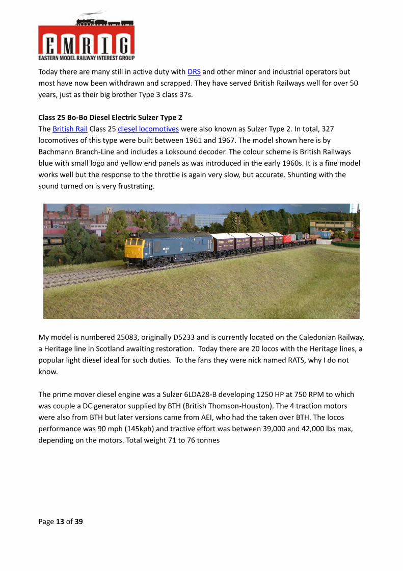
Class 25 Bo-Bo Diesel Electric Sulzer Type 2
The British Rail Class 25 diesel locomotives were also known as Sulzer Type 2. In total, 327
locomotives of this type were built between 1961 and 1967. The model shown here is by
Bachmann Branch-Line and includes a Loksound decoder. The colour scheme is British Railways
blue with small logo and yellow end panels as was introduced in the early 1960s. It is a fine model
works well but the response to the throttle is again very slow, but accurate. Shunting with the
sound turned on is very frustrating.
My model is numbered 25083, originally D5233 and is currently located on the Caledonian Railway,
a Heritage line in Scotland awaiting restoration. Today there are 20 locos with the Heritage lines, a
popular light diesel ideal for such duties. To the fans they were nick named RATS, why I do not
know.
The prime mover diesel engine was a Sulzer 6LDA28-B developing 1250 HP at 750 RPM to which
was couple a DC generator supplied by BTH (British Thomson-Houston). The 4 traction motors
were also from BTH but later versions came from AEI, who had the taken over BTH. The locos
performance was 90 mph (145kph) and tractive effort was between 39,000 and 42,000 lbs max,
depending on the motors. Total weight 71 to 76 tonnes

Page 14 of 39
In conclusion a good buy and fits in nicely with my 1960s era model railway.
Class 31 A1A-A1A Diesel Electric Brush Type 2
The Class 31 Diesel Electric locomotive was developed as a result of the British Transport
Commission’s 1955 Modernisation Plan which proposed replacing all steam engines with diesel
over a 10 year period. Locomotive builders were invited to produce small fleets of a pilot design
that could be tested hopefully leading to large scale orders. Designed and built by Brush Traction at
Loughborough the early examples were delivered to London’s Stratford Depot for use on the
former Great Eastern Lines with the prototype D5500, the first of a batch of twenty being delivered
in October 1957. The complete pilot batch entered traffic during the years 1957-59 with the
majority going to East Anglia sheds.

Page 15 of 39
The BTC were impressed with the Class and orders were placed for production locos with a total of
263 Class 31’s being built by 1962. They had standard electro-pneumatic controls with the BR Blue
Star multiple working systems. Between 1965 and 69 the entire class was re-engined with English
Electric power units after serious problems with the Mirrlees power units. As the class numbers
grew their sphere of operation increased and they could be found all over the BR network working
both passenger and freight trains.
The model pictured above is a recent addition to my roster and a fine model it is. It is fitted with a
Loksound decoder which produces excellent and accurate sound of the diesel engine and all other
loco sounds, including a guard’s whistle! Performance is exemplary; Hornby have again excelled
and in my opinion are better in performance and value than Bachmann. For a general purpose
medium powered loco this is an excellent choice.
The A1A-A1A designation means that the loco has two 3 axle bogies but only the outer axles are
driven with the centre axle being unpowered. The power classification was Type B, later Type 2,
the engine developing 1250 HP
Between 1973 and 85 sixty eight locos were fitted with electric train heating and all examples still

Page 16 of 39
in traffic in 1988 were fitted with dual train brakes, air and vacuum. From 1983 a life extension
programme was undertaken involving the removal of body side bands and skirts together with
redundant steam train heating equipment. Any loco not in this programme was earmarked for
early withdrawal but the last ones continued in service till 1994. Today the only class 31’s
operational on the national system belong to Fragonset? Railways and Network Rail.
In the next instalment I will include some of the following, subject to keeping the article to 4-5
pages.
Class 47 Co-Co Diesel Electric, Brush Type 4
Class 50 Co-Co Diesel Electric English Electric Type 5
Class 55 Co-Co Diesel Electric English Electric Type 5 Deltic
Class 60 Co-Co Diesel Electric Brush Type 5
Class 66 Co-Co Diesel Electric, the American intruder”
And maybe my American General Motors EMD GP38 and GP 40 tandem pair!

Page 17 of 39
Silent no More.
By John Burkhardt
FRATESCHI SAR CLASS 34 Part 2
5. Body Shell modifications
We now retrieve the tray with all the body parts that we disassembled from the chassis in part 1, and turn
our attention the body shell itself. On the inside top the manufacturer left a nasty stump of the casting
spruce, which if left will not give us enough clearance between moor and roof to house our decoder. Hence
with a suitable Dremel mill head we have to remove it to leave a smooth surface.
Spruce removal
In this second part of the Frateschi install we take care of all the necessary body & cab modifications to install proper
head and back up light as well as prepare and install all the parts that are essentially going to be part and fixture in
the body shell before we assemble it with the chassis for testing and programming. As I particularly object to how the
lighting is done in this model I spend quite some time on modifying small parts to improve overall appearance which
will only become apparent when you view the video showing the Loco in operation, and that will all be in Part 3 next
month.

Page 18 of 39
While busy in there we cut a suitable size of black styrene to glue over the exhaust opening to close it for
later weathering so as not see any decoder tracks or wires through the rather large opening.
Closing of Exhaust Stack
Next we remove the backup light lens, but this time I was not successful so I used the same mill head in the
Dremel to remove the two large cones (see later in cab) that protrude out into the shell. Mill as close as
comfortable to the plate and as smooth as possible and when we glue in the LED holder in place, we give it
a wipe with MEK to get it perfectly clear again.
Backup Light Lens shortened
Page 19 of 39
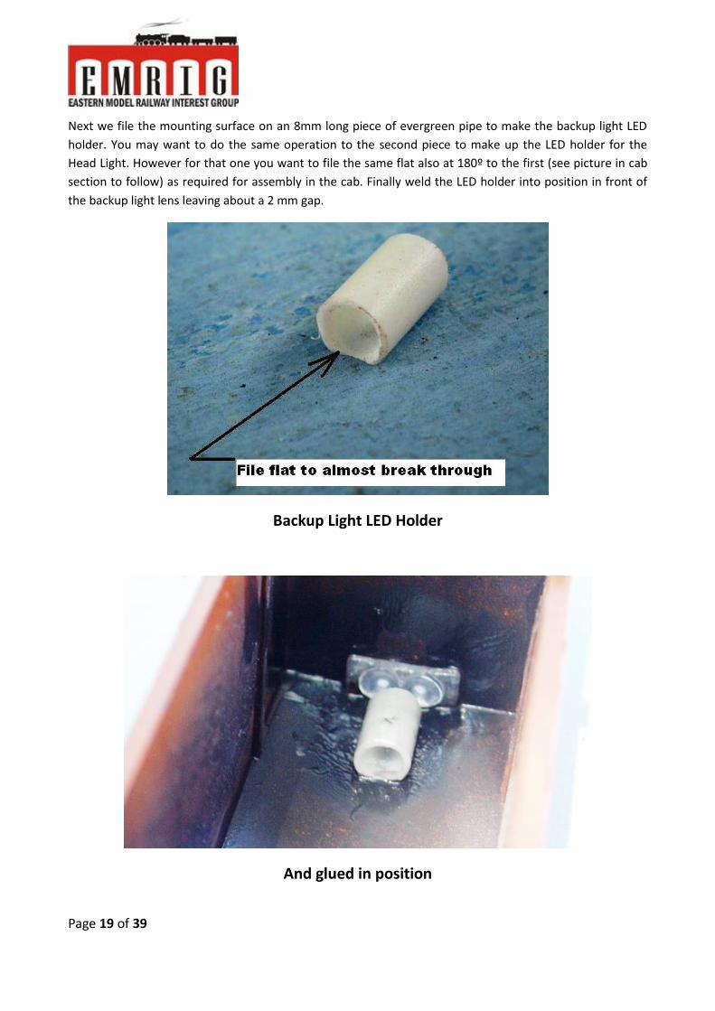
Next we file the mounting surface on an 8mm long piece of evergreen pipe to make the backup light LED
holder. You may want to do the same operation to the second piece to make up the LED holder for the
Head Light. However for that one you want to file the same flat also at 180º to the first (see picture in cab
section to follow) as required for assembly in the cab. Finally weld the LED holder into position in front of
the backup light lens leaving about a 2 mm gap.
Backup Light LED Holder
And glued in position
Page 20 of 39
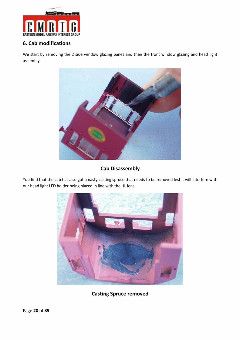
6. Cab modifications
We start by removing the 2 side window glazing panes and then the front window glazing and head light
assembly.
Cab Disassembly
You find that the cab has also got a nasty casting spruce that needs to be removed lest it will interfere with
our head light LED holder being placed in line with the HL lens.
Casting Spruce removed

Page 21 of 39
Next we nick the connecting material between HL & front window glazing in that Assy to allow us to safely
break the two entities apart.
Separating HL Lenses from Front Window Glazing
On the Lens part we want to trim those large cones away so that we are left with the actual HL lenses and
the plate that holds the two lenses together. File the back smooth and later we get them perfectly clear
again with wipe of MEK as we’ve done for the backup light lenses.

Page 22 of 39
Shorten the Head Light Lens Assy
Trim the connecting plate all round, down close to the diameter of the lens stems, and insert back into the
lens holes in the cab after giving it a smear of MEK to weld them in place permanently.
Final HL Lens Assy
On the front window glazing you want to smooth away all traces of the break and then file a 45º bevel on
the inside ensuring not to touch the actual window square so that when reinserted the full window aper-
ture is still completely filled with glazing.
Front Window Glazing ready for mounting

Page 23 of 39
Once both the front glazing and the HL lens Assy are welded into their respective place we should have at
least a 1 mm gap between them to accept the thickness of the ceiling board (1+mm?), but when fitting the
glazing make sure no MEK flows onto the window pane surface!
Window Glazing & HL Lens back in place
The reason for the space between the HL Lens Assy and Window Glazing is to allow the ceiling board to
slide properly between them to prevent light from the HL to be conducted into the window Glazing. That is
also why we filed two flats onto the LED holder to give us another support for the ceiling board in the cen-
ter.
Head Light LED Holder with flat top and bottom
Page 24 of 39
If we’re done the smoothing of the cab roof and filing of the LED Holder correctly, its top flat should be in
line with the top of the Lens Assy. Take care when welding the LED holder in place to leave at least a 2 mm
gap between holder and lens and that the center line of the LED holder is as close as possible in line with
the middle of the HL Lens and is perfectly in line with the loco axis.
HL LED Holder welded in place
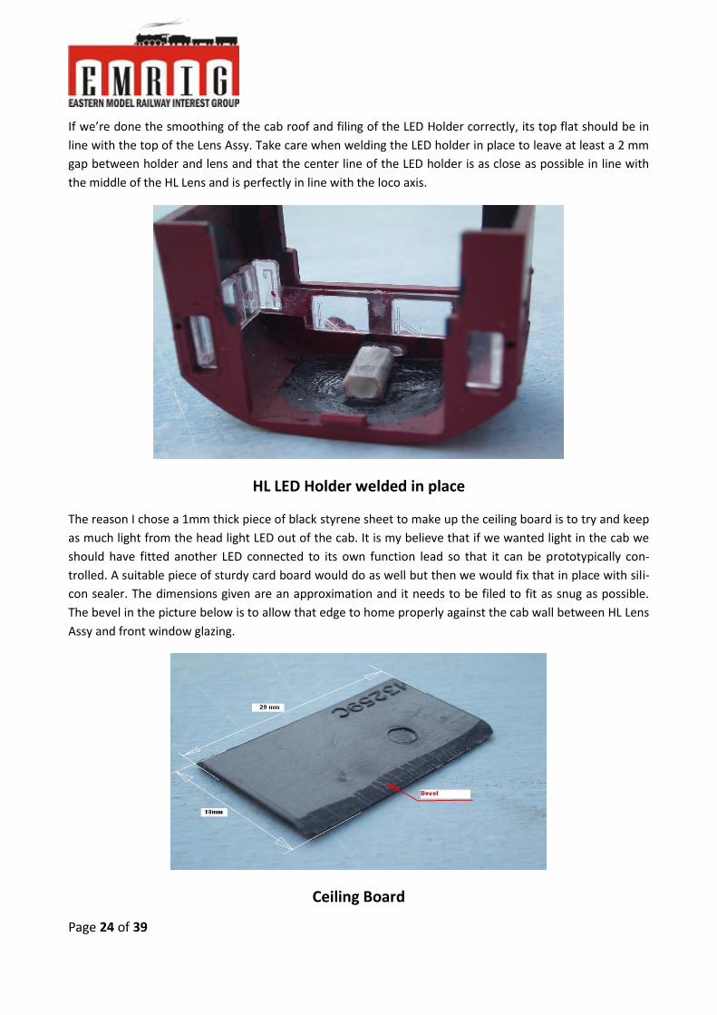
The reason I chose a 1mm thick piece of black styrene sheet to make up the ceiling board is to try and keep
as much light from the head light LED out of the cab. It is my believe that if we wanted light in the cab we
should have fitted another LED connected to its own function lead so that it can be prototypically con-
trolled. A suitable piece of sturdy card board would do as well but then we would fix that in place with sili-
con sealer. The dimensions given are an approximation and it needs to be filed to fit as snug as possible.
The bevel in the picture below is to allow that edge to home properly against the cab wall between HL Lens
Assy and front window glazing.
Ceiling Board

Page 25 of 39
Turn the ceiling board over and file a bevel at each end shaped such as to allow the styrene plate to make
contact with the curved cab roof for a better bonding area when welding the ceiling into the cab roof.
Bevel Ceiling Board on sides
Apply MEK to the cab roof and on top of the LED holder as well as to the appropriate edges and places on
the ceiling board and weld the ceiling into place to complete the cab modifications, then snap the cab Assy
back into the body shell.
Completed Cab Assy
Page 26 of 39
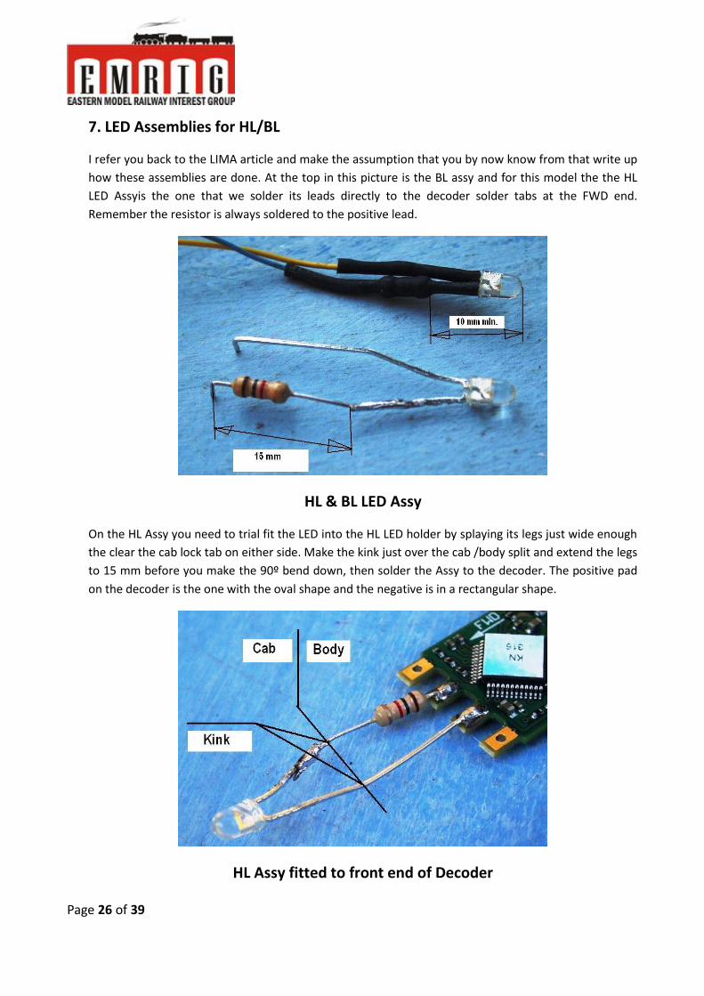
7. LED Assemblies for HL/BL
I refer you back to the LIMA article and make the assumption that you by now know from that write up
how these assemblies are done. At the top in this picture is the BL assy and for this model the the HL
LED Assyis the one that we solder its leads directly to the decoder solder tabs at the FWD end.
Remember the resistor is always soldered to the positive lead.
HL & BL LED Assy
On the HL Assy you need to trial fit the LED into the HL LED holder by splaying its legs just wide enough
the clear the cab lock tab on either side. Make the kink just over the cab /body split and extend the legs
to 15 mm before you make the 90º bend down, then solder the Assy to the decoder. The positive pad
on the decoder is the one with the oval shape and the negative is in a rectangular shape.
HL Assy fitted to front end of Decoder

Page 27 of 39
8. Speaker prep and Decoder Assy
I’m fortunate that I have a sanding wheel in my work shop as we need to grind the 20mm wide bass re-
flex speaker Assy to fit into the 18mm wide body shell. I grind each side wall until the speaker slides in-
to the body with light pressure. In this process you may be breaking through the enclosure walls but
this is of no consequence as we will seal it again with the body side walls.
For grinding the speaker enclosure side walls
When the speaker is prepared lay it in line behind the speaker and measure how long to cut the speak-
er leads so they reach the S+ & S- tabs on the side of the decoder yet maintaining at least 5mm space
between speaker and decoder end.
Decoder Assembly Overview

Page 28 of 39
As I strife to reduce all wire length to the bare minimum (less chance of rubbing and/or snagging) I also
reduce the length of the capacitor leads to a length so that the capacitor can just clears the FWD end of
the decoder. However, you can simply put a double fold into the leads to achieve the same positioning
of the Cap for later cementing in place. Now first solder the red and black track leads to the appropriate
tabs as well as the blue and yellow leads of the BL LED Assy and orient all these wires to lead towards
the FWD end of the decoder.
Soldering Leads to Decoder end
Now solder the grey and orange motor leads followed by the speaker leads to the appropriately
marked tabs on the decoder sides. Use a 10mm piece of shrink tubing to bundle red, black, orange and
grey together and push back as far as will go then heat to keep the four wires together at the decoder,
pointing towards the front to complete the Decoder Assy.
Soldering Leads to Decoder sides

Page 29 of 39
To fit the Decoder Assy into the shell start by carefully threading the HL LED into the holder located un-
der the ceiling board and use a pointed tool (strong needle?) to push the LED home firmly yet taking
care not to dislocate LED Holder and/or ceiling board! This should force the decoder to lay flat on the
body roof with the BL and speaker dangling outside the body, but the LED legs may need a bit of bend-
ing to keep the decoder from lifting at the other end. In the picture note the capacitor position where
we will later fix it with a dollop of silicon sealant. Also note that as a result of the HL LED and the speak-
er leads the decoder will be held in position and will not need any further fixing.
Decoder & Capacitor positioning
Next we shove the BL LED into its holder and push it home by grabbing the resistor lead behind its body
with a strong tweezers or long nose pliers, then spread the leads so that the wires will clear the exhaust
cover, which will keep the speaker floor at a height to let the blue and yellow wire pass under it. Keep
these wires in place with a smear of silicon skirting said exhaust cover. Then lightly coat the sides of the
speaker that we ground, and press it firmly down into the body making sure it is only the thickness of
the cover and/or wires away from the body roof.
BL LED and Speaker are in

Page 30 of 39
The Decoder, Lights and Speaker fitment is now done and all that remains is to place a blob of silicon
under the capacitor and we can set the assembly aside to let the silicon set.
Decoder fitment done!
Foot note 1:
Why I like to use the silicon sealer to bond my components in place is that it is firm enough a bond yet
can easily be prised out again if need be and cleaning of the components is easily done with a firm rub.
Foot Note 2:
Although the 20 x 58 mm bass reflex speaker assembly to my ear gives me the best balance between
volume and timbre we possibly could get similarly good results with a closed coupled array of 2 or 4
PAD’s but at increased costs.
This concludes part 2 of the Frateschi install. Next month, in part 3, we will finish the assembly of this loco,
then program the decoder before filming the test run on the layout.
John Burkhardt 2016.04.25

Page 31 of 39
The EMRIG Water Tower Challenge.
By Colin Anstis
What is “Wet Water” and Chemical Track Cleaning?
Much to my surprise and then horror, on reading the April issue of the EMRIG Newsletter, I realised
that I had been nominated to submit the “Water Tower” article for the May issue.
I instantly thought,” I hope that due to other pressing matters that Colin T.T and Glynn may have,
that the next issue would be delayed until at least Christmas”. (Ed: - LOL).
Actually, as a member who has only been with the club for two and a half years, I felt quite
honoured to have been nominated by Peter.
Not being an electrical nor mechanical wizard and only having a basic understanding of the
complexities involved with model railroading, I was at a bit of a loss as what to write about,
especially after Peter’s article on his train journeys as a youth in Rhodesia/Zimbabwe, published in
the April edition.
Being an Industrial Chemist by training and having earned my keep in this line of work, I thought
that I might just put some simple facts together on the chemistry side of model railroads.
Listening to club members talk about ballasting techniques and track cleaning, these seemed to be
subjects that, although everybody uses in day to day model railroading, the “ why” may not be
known.
Editors’ notes: -
I have said this before and I will say it again, the quality of the articles being posted by the authors of the “Water
tower Challenge” is out of this world. To be very honest, when Colin Anstis phoned me proposing this article, I was a
little apprehensive. I mean, what can you write about wet water??? BUT, I did ask guys to write on anything they
wanted!
To say Colin has written one very interesting and professional article is an understatement. I thoroughly enjoyed this
article and certainly hope you do to. I must say, I do worry the day when I am nominated for an article again. The
reason being that I have nothing to match the quality the Water Tower Challengers have been doing. To say I have
shot myself in the foot is an understatement!

Page 32 of 39
“Wet Water”
All articles and video’s on ballasting make reference to wetting the dry ballast once laid down, this
is normally tap water with a few drops of liquid detergent and in some cases a small amount of
alcohol added, this mixture is then sprayed as a fine mist onto the dry ballast.
Then a 50:50 white glue*: water solution ,with a few drops of liquid detergent and/or alcohol
added, is slowly dropped onto the wetted ballast, allowed to penetrate then allowed to dry
overnight , resulting in a firm clear solid ballast.
*NOTE: White glue, in this case polyvinyl acetate (PVAc). Normally the longer the polymer
molecule the more tack you get with the glue, which could affect the penetration of the mixture.
We all know that the liquid detergent and/or the alcohol helps the water (in the first instance) and
then the glue mixture to penetrate right through the ballast to give the desired result, but how
does this happen?
All liquids in contact with a gas (in our case air) have a surface tension, this is like a thin elastic skin
and can be measured by various techniques and is expressed as dynes per centimeter (dyne/cm)
or Newton’s per meter (N/m)
Water has a relatively high surface tension of 72 dynes/cm and due to this has difficulty
penetrating our ballast, added to this is the irregular shape and surface area of each piece of
ballast, made even worse when two pieces of ballast are in close contact with each other.
To overcome the relatively high surface tension of water we need to lower it by addition of other
chemicals that are miscible with water and can act on the surface of the water, some of these are
known as surfactants (surface active agents).
They are divided into three main groups, these are,
Anionic - a molecule with a negative head and a positive tail - 0---------- +
Cationic - a molecule with a positive head and a negative tail - -----------0 +
Non ionic - neutrally charged
As all these types are mostly water soluble and serve our purpose, we do not need to delve into
the chemistry of surfactants, only to say, that in general, the cationic surfactant has the ability to
lower the surface tension more than the other two types.

Page 33 of 39
These surfactant molecules have the ability to align themselves at the surface of the water
lowering the contact angle of the water on the ballast (in simple terms changing the shape of a
drop of water from a sphere to a pancake) thereby allowing more water surface to contact the
total surface of the ballast material and in turn allowing more penetration.
Many common liquids (most of them readily available to us) have a much lower surface tension
than water and importantly are miscible with water. I have given below the figures for the most
common components used in the mixtures we use.
Compound Surface tension (dynes/cm) Type
Water 72
Alcohol (pure) 22 Ethanol
Alcohol (10%) 46 Ethanol/water
Surfactant (e.g. dishwashing liquid) 30 Anionic/Non ionic
Surfactant (e.g. fabric softener) 20 Cationic
As our objective is to get the surface tension as low as possible,(ideally 30 dynes/cm or lower), to
achieve penetration throughout the ballast we would look at the compound that achieves this with
the lowest surface tension reading, we have ignored cost, availability and safety, so a choice must
be made with what is readily available to us.
Various tests have shown that a surface tension of about 30 dynes/cm can be achieved if a 40%
solution of alcohol is used, while only a solution of 0.5% of surfactant (anionic type) will give the
same result.
It is important here to understand that commercially available liquid detergents only contain
between 12 to 30% surfactant, therefore compensation in your mixture must be made for this
lower concentration
If one had access to the specialised types of surfactant as those used in firefighting liquids, self
leveling polishes and ore recovery enhancers it would only require a 0.1% solution to achieve a
surface tension of about 17 dynes/cm.

Page 34 of 39
Summary table of possible mixtures
Compound Percentage in mixture Surface tension
(dynes/cm)
Water 100 72
Alcohol/water 40 30
Detergent/water 0.5 30
Specialised surfactant/water 0.1 17
A mixture of liquid detergent and alcohol is often used, but as can be seen from above, no
significant drop in surface tension will be achieved unless high percentages of alcohol are used.
What has been discussed above has been on lowering the surface tension of water, but to a
greater or lesser degree will hold true for the white glue mixture as well, (no information on
surface tension of white glue available)
While writing this article a few thoughts crossed my mind, in preparing the white glue/water
solution I use.
To this end I decided to measure the pH of my white glue mixture and found it to be 5.0 (an acid
solution).This type of pH would lend itself to using cationic surfactants as they are quite compatible
with acid pH’s but opposed to this, some liquid washing-up detergents might cause a problem and
not work as well in that they contain anionic surfactants which prefer alkaline pH’s. Some
investigation is now required in using fabric softeners in place of liquid detergents in the glue
mixture
I have tried to give a brief overview of basic surface tension and the reasons why it helps in making
water more “wet”, I am therefore not advocating that all the tried and trusted formulae that are
used out there be changed, but that hopefully if you have had problems you may understand the
possible reasons for these.
Chemical Track Cleaning
Another subject talked about a lot at the club has to do with track cleaning, here again not trying
to change well established methods, but looking at it purely from a chemical perspective.
It is well known that a clean track and clean wheels make for good running, so they have to be
cleaned regularly, a task most of us dislike, so do not go looking for the short cut nor the ultimate
answer in this short article.
Page 35 of 39
My starting point was to try and establish what “track dirt” is and by knowing this, apply some
thought as how to remove it. As the majority of people now use nickel-silver rails, I looked at this
system only, but besides the metal contaminants being different for steel rails the organic matter
would be the same.
Most of the sources I found referred to three main groups of soil, these were,
Fine metal, from friction (rail/wheel contact) and abrasion cleaning
Metal oxides, from electrical arcing and an electrolysis effect caused by dissimilar metals in
the track and wheels
Organic matter (“crud”), from lubricants, dust and cleaner residues
I could only find one reference (source unknown) to the percentage composition of track dirt; it
was given as follows, (for nickel/silver rails)
57% Copper
29% Zinc
0.6% Nickel
0.6% Lead
2.0% Organic matter
I have only focused on the organic matter component of the above analysis and have left the metal
composition to those more knowledgeable than myself as to their possible sources.
We would be able to remove these metal components using chemical means (acids), but as these
acids would also attack the metal rails and be a safety risk, we will only focus on the organic matter
and how to deal with it.
The organic matter acts as a binder to the metal elements keeping them together in a black “crud”
like paste, if this could be removed or dissolved, it would free the metal components from the
paste and in turn from the rails, thereby leaving a clean track, this using a wipe-on/wipe-off
method.
The soil is now known, the metal used in the rail is known, this only leaves one other unknown and
that is the plastic in the sleepers/rail ties. This now creates another problem in that a lot of very
good cleaning solvents have to be ignored as they are severely aggressive to plastics.

Page 36 of 39
By using the above information and by an elimination process it is obvious that a suitable solvent
or formulated cleaner should be found to remove the organic matter, this solvent or cleaner should
not attack the plastic sleepers/rail ties, nor the metal rails, be safe and lastly be readily available.
The options available to us then are,
Water based degreasers (Clean Green type) – obviously not suitable due to slow
evaporation rate and possible residues being left behind on the rails, (these are formulated
products and contain various types of chemicals).
Formulated solvent cleaner – Mostly imported, extremely expensive, sometimes do not
work that well.
Light oils –Softens the organic matter to assist removal in a wipe-on/ wipe-off application,
any residues left behind are non-conductive.
Solvents – must not attack the plastic sleepers/rail ties, must be similar in make-up to the
organic matter, preferably a hydrocarbon based solvent, be safe (non-toxic, etc) readily
available and not be too volatile and evaporate too quickly or evaporate too slowly leaving
a residue.
By elimination it would seem as if finding a suitable solvent cleaner is the route to follow, there are
many choices available off the shelf, but remember to check compatibility with the track
components ( plastic sleepers/rail ties, rails and electrical wire insulation) as well as all the safety
aspects (toxicity, flammability etc) before use.
You may have already found the one that suits your particular situation or now you may want to
experiment with what is available but whichever it is, remember keep those tracks clean.
Therefore, after delving into this subject, my focus will be on finding the correct solvent with which
to clean my rails.
NOTE: As this is a chemical perspective on track cleaning, I have not touched on the use of
mechanical abrasive cleaning, these have a place in track cleaning, but maybe somebody else can
tackle this subject.
But as I mentioned at the beginning of this treatise, it was not written to change well established
practises, but to offer a brief chemical insight to these subjects that most of us seem to discuss,
and to try and have a purely analytical look at them from my point of view.
Thank you

Page 37 of 39
As a “newbie” to EMRIG I would like to give another “newbie” the chance to express his views,
therefore I would like to nominate Dave Wynne for the next Water Tower Challenge.
Water Tower Challenge Honour board
• 2015 October Glynn Chamberlain
• 2015 November Niel Wilson
• 2015 December Terrance Marx (Part 1)
• 2016 January Terrance Marx (Part 2)
• 2016 February Terrance Marx (Part 3)
• 2016 March Terrance Marx (Part 4)
• 2016 April Peter Fish
• 2016 May Colin Anstis

Page 38 of 39
Upcoming Duty Roster
Hi guys. Over the past month, one or two folk have missed their respective “Duty Roster” date.
Fortunately due to the regulars, they have opened up and it has been business as usual. For
reference, we will include the duty roster up to the end of the following month for the
respective newsletter published. So, in this article, below is the Duty Roster till the end of June.
Cell numbers have been removed due to this newsletter being public; however, they are on the
duty roster list on the noticeboard at the club.
As always, if you cannot make your assigned slot, make a plan with someone.
Date Name Date Name
2 Sat 14-05 Terence M 3 Wed 18-05 Dave Wynne
3 Sat 21-05 Kobus P 4 Wed 25-05 Colin TT
4 Sat 28-05 Colin A 1 Wed 01-06 Clive Sheppard
1 Sat 04-06 Colin TT 2 Wed 08-06 Colin A
2 Sat 11-06 Peter F 3 Wed 15-06 Dave Wynne
3 Sat 18-06 Theuns W 4 Wed 22-06 Colin TT
4 Sat 25-06 Glynn C 5 Wed 29-06 John H
Club Diary:-
Saturday the 28th May, EMRIG Swap Meet.
Saturday the 24th September, EMRIG Swap Meet.
Saturday the 17th December EMRIG Swap Meet.
Page 39 of 39
Club Contact details:-
Chairman – Colin Tanner-Tremaine – [email protected] – 0828280665
Secretary – Peter Fish – [email protected]
Treasurer – Colin Tanner-Tremaine – [email protected] – 0828280665
Webmaster – Glynn Chamberlain – [email protected]
Club Banking Details:-
Banking details: -
Bank: - FNB Northmead Square
Name: - Eastern Model Railway Interest Group
Account No: - 625 483 74149
Branch code: - 250 112. Please, DO NOT forget to put your name as reference.