nfpa-52 2010 chapter 8 - tulsa gas technologies · nfpa-52 2010 chapter 8. 7/9/2012 2 ... nfpa 70,...
TRANSCRIPT

7/9/2012
1
NFPA-52 2010
Chapter 8
7/9/2012
2
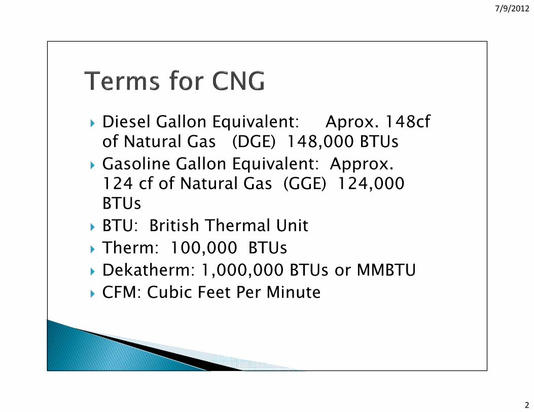
� Diesel Gallon Equivalent: Aprox. 148cf of Natural Gas (DGE) 148,000 BTUs
� Gasoline Gallon Equivalent: Approx. 124 cf of Natural Gas (GGE) 124,000 BTUs
� BTU: British Thermal Unit
� Therm: 100,000 BTUs
� Dekatherm: 1,000,000 BTUs or MMBTU
� CFM: Cubic Feet Per Minute

7/9/2012
3
Slow FillSlow FillSlow FillSlow Fill ( Time Fill) Where a vehicle sits for hours to be refueled by small compressors
VRAVRAVRAVRA Vehicle refueling appliance ( Home Refueling)
Fast FillFast FillFast FillFast Fill Where Natural gas is received from the gas company, run through a compressor to storage cylinders then dispensed into a vehicle ( Refuel time is 5 to 7 minutes)

7/9/2012
4
25% Full
3
2
1
50% Full
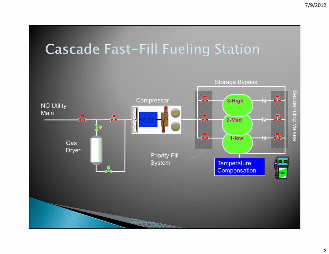
Temperature
Compensation
NG Utility
Main75% Full
Gas
Dryer
Compressor
7/9/2012
5
Gas
Dryer
NG Utility
Main
Temperature
Compensation
Storage
Priority Fill
System
Sequencing Valves
Storage Bypass
Compressor
CNG
Cascade
1-low
2-Med
3-High

7/9/2012
6
8.38.38.38.3 General System Requirements
8.3.18.3.18.3.18.3.1 Where systems are served by a gas utility, the utility shall be notified of all CNG installations.
8.3.48.3.48.3.48.3.4 Vehicles shall not be considered a source of ignition with respect to the provisions of this chapter
(Exception) Vehicles containing fuel-fired equipment.
8.3.78.3.78.3.78.3.7 Compression equipment shall be designed for use with CNG and for the pressures and temperatures to which it can be subject under normal operating conditions.

7/9/2012
7
8.3.88.3.88.3.88.3.8 Compression equipment shall have pressure relief devices that limit each stage pressure to the maximum allowable service pressure for the compression cylinder and piping associated with that stage of compression
8.3.98.3.98.3.98.3.9 Where CNG compression equipment is operated unattended, it shall be equipped with high discharge and low suction pressure controls.
8.3.10 8.3.10 8.3.10 8.3.10 Control circuits that SHUT DOWN shall remain down until manually activated or reset after a safe shutdown is performed.

7/9/2012
8

7/9/2012
9
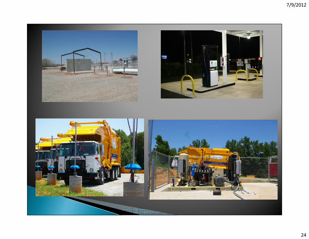
8.4.2 Outdoors8.4.2 Outdoors8.4.2 Outdoors8.4.2 Outdoors
8.4.2.2 A facility in which CNG Compression, storage, and dispensing equipment are sheltered by an enclosure that is constructed of non combustible or limited-combustible materials and that has at least one side predominantly open and a roof designed for ventilation and dispersal of escaped gas shall be considered to be located out doors.
8.4.3.12 Indoor fast8.4.3.12 Indoor fast8.4.3.12 Indoor fast8.4.3.12 Indoor fast----filling, Outdoor storage, and filling, Outdoor storage, and filling, Outdoor storage, and filling, Outdoor storage, and CompressionCompressionCompressionCompression
Fast-filling fueling indoors shall be permitted where storage and compression equipment is located outdoors complying with 8.4.2.1 Through 8.4.2.7 and 8.4.2.9.

7/9/2012
10

7/9/2012
11
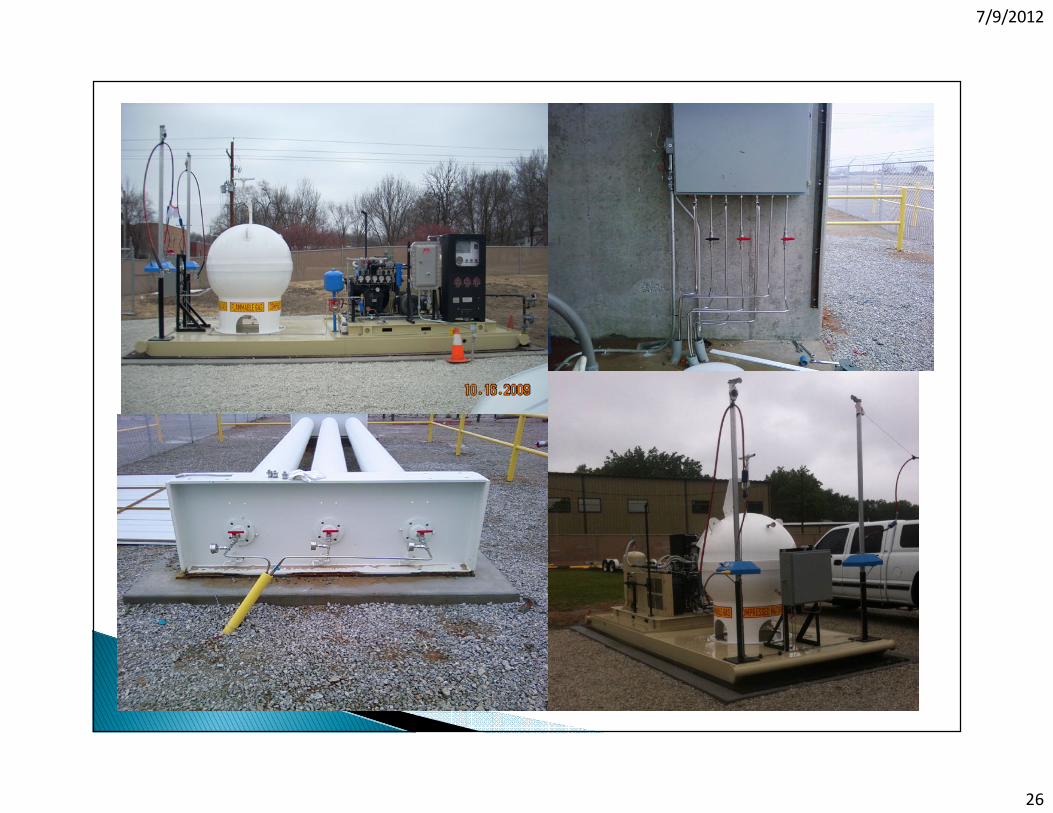
8.5.18.5.18.5.18.5.1 Storage containers shall be installed above ground on stable, noncombustible foundations or in vaults with ventilation and drainage.

7/9/2012
12
8.5.1.18.5.1.18.5.1.18.5.1.1 Horizontal containers shall have no more than two points of support longitudinally.
8.5.2.18.5.2.18.5.2.18.5.2.1 Horizontal installed containers shall not be in direct contact with each other.
8.5.2.28.5.2.28.5.2.28.5.2.2 Composite containers shall be protected from UV radiation as required by manufacture.

7/9/2012
13
8.6.18.6.18.6.18.6.1 Pressure relief valves shall be so arranged that they discharge to a safe area and so that escaping gas does not impinge on a building, other equipment, or areas that could be occupied by the public.
8.6.38.6.38.6.38.6.3 An over pressure protection device, other than a rupture disc, shall be installed in a fueling transfer system to prevent overpressure in the vehicle.
8.6.4 8.6.4 8.6.4 8.6.4 The set pressure of the over pressure protection device shall not exceed 125 percent of the set pressure of the fueling nozzle it supplies.( Typically 3000 nozzle 3750 psi, 3600 nozzle 4500 psi)
7/9/2012
14

7/9/2012
15
8.8 Installation of pressure gauges8.8 Installation of pressure gauges8.8 Installation of pressure gauges8.8 Installation of pressure gauges.
Gauges or other readout devices shall be installed to indicate compression, discharge pressure, storage pressure, and dispenser pressure

7/9/2012
16
8.9.1.1 8.9.1.1 8.9.1.1 8.9.1.1 Exterior piping shall be either buried or installed above ground and shall be supported and protected against mechanical damage
8.9.1.28.9.1.28.9.1.28.9.1.2 Underground piping shall be buried not less than 18” below the surface of the ground unless otherwise protected from damage by movement of the ground
8.9.1.38.9.1.38.9.1.38.9.1.3 Underground and aboveground piping shall be protected from corrosion in compliance with recognized practices.
8.9.1.4 8.9.1.4 8.9.1.4 8.9.1.4 Threaded pipe and fittings shall not be used underground.

7/9/2012
17

7/9/2012
18

7/9/2012
19
8.10.1 8.10.1 8.10.1 8.10.1 Piping, tubing and hose and hose assemblies shall be leak tested after assembly to prove them free from leaks at a pressure equal to at least the normal service pressure of that portion of the system.
8.10.1 8.10.1 8.10.1 8.10.1 Pressure relief valves shall be tested at least every 3 years....

7/9/2012
20
8.11.1 Manually Operated Container Valve8.11.1 Manually Operated Container Valve8.11.1 Manually Operated Container Valve8.11.1 Manually Operated Container Valve
8.11.1.1 8.11.1.1 8.11.1.1 8.11.1.1 A manually operated container valve shall be provided for each DOT and TC storage cylinder.
8.11.1.2 8.11.1.2 8.11.1.2 8.11.1.2 Each group of ASME storage vessels up to a maximum combined capacity of 10,000 scf shall be provided with a manually operated shutoff valve.
8.11.1.38.11.1.38.11.1.38.11.1.3 A manually operated shutoff valve shall be installed as close to a container or group of containers as practical.
8.11.58.11.58.11.58.11.5 A emergency Manual shutdown device shall be provided with in 10ft of the dispensing area and also greater than 25ft from the dispensing area.

7/9/2012
21
7/9/2012
22
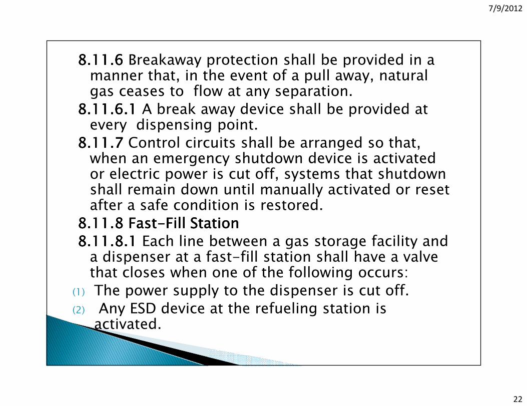
8.11.68.11.68.11.68.11.6 Breakaway protection shall be provided in a manner that, in the event of a pull away, natural gas ceases to flow at any separation.
8.11.6.18.11.6.18.11.6.18.11.6.1 A break away device shall be provided at every dispensing point.
8.11.7 8.11.7 8.11.7 8.11.7 Control circuits shall be arranged so that, when an emergency shutdown device is activated or electric power is cut off, systems that shutdown shall remain down until manually activated or reset after a safe condition is restored.
8.11.8 Fast8.11.8 Fast8.11.8 Fast8.11.8 Fast----Fill StationFill StationFill StationFill Station
8.11.8.18.11.8.18.11.8.18.11.8.1 Each line between a gas storage facility and a dispenser at a fast-fill station shall have a valve that closes when one of the following occurs:
(1) The power supply to the dispenser is cut off.
(2) Any ESD device at the refueling station is activated.

7/9/2012
23
8.12.18.12.18.12.18.12.1 Fixed Electrical equipment and wiring with in the area in Table 8.4.2.9 shall comply with table 8.4.2.9 and shall be installed in accordance with NFPA 70, NEC
Summary:Summary:Summary:Summary:
Every thing inside the dispenser cabinet is Class 1 Div.1 group D
Outside the dispenser with in 5 feet in every direction Class 1 Div.2 Group D
Compressor area is Class 1 Div. 2 Group D.
8.12.38.12.38.12.38.12.3 Classified areas shall not extend beyond a un-pierced wall, roof, or vapor tight partition.
7/9/2012
24

7/9/2012
25
8.12.28.12.28.12.28.12.2 With the approval of the AHJAHJAHJAHJ, classified areas specified in Table 8.4.2.9 shall be permitted to be reduced or eliminated by positive pressure ventilation from a source of clean air or inert gas in conjunction with effective safe guards against ventilator failure by purging methods recognized in NFPA 496.
Note, Note, Note, Note, Some dispenser and compressor manufactures are using this method of creating a safe area with in a Class 1 Div. 1 Group D environment. This method required constant follow up to prevent tampering with the air-purge system.
8.13.28.13.28.13.28.13.2 Static protection shall not be required where CNG is transferred by conductive or non conductive hose, flexible metallic tubing, or pipe connections where both halves of the metallic couplings are in continuous contact.
7/9/2012
26

7/9/2012
27

7/9/2012
28

7/9/2012
29

7/9/2012
30

7/9/2012
31

7/9/2012
32

7/9/2012
33

7/9/2012
34

7/9/2012
35

7/9/2012
36

7/9/2012
37

7/9/2012
38

7/9/2012
39
BRC FUELMAKER MODEL FMQBRC FUELMAKER MODEL FMQBRC FUELMAKER MODEL FMQBRC FUELMAKER MODEL FMQ
With the FuelMaker Model FMQ you can fuel your car at work or home safely, practically, and economically.It can be easily installed at your company or home's premises and directly charged to your gas bill costs!
<>