ngx blueboard-lpc11u24 keil mdk user manual · ngx blueboard-lpc11u24 keil mdk user manual from ngx...
TRANSCRIPT
NGX BlueBoard-LPC11U24 KEIL MDK User
Manual
From NGX Technologies Knowledgebase
Contents
1 INTRODUCTION
1.1 Setup for ULINK2 and BLUEBOARD-LPC11U24/37 Board
1.2 Configuration of ULINK2 Debugger
2 BLUEBOARD-LPC11U24/37 Software Development
2.1 Executing the sample projects
2.2 Creating New project
2.3 Creating Bin File
3 BLUEBOARD-LPC11U24/37 Programming
3.1 Programming options
3.1.1 On-Chip bootloader (USB or UART)
3.1.2 Flashing the board using USB
3.2 Flashing the Hex file through UART
4 Schematic & Board Layout
4.1 Schematic
4.2 Board layout
5 Trouble Shooting
INTRODUCTION
This document is the User Manual for the BLUEBOARD-LPC11U24/37, a low cost ARM Cortex-M0 based
board by NGX Technologies. This document reflects its contents which include system setup, debugging,
and software components. This document provides detailed information on the overall design and usage of
the board from a systems perspective.

Before proceeding further please refer the quick start guide for BLUEBOARD-LPC11U24/37 features and
BLUEBOARD-LPC11U24/37 verification.
For BLUEBOARD-LPC11U24/37 Quick Start Guide: BlueBoard-LPC11U24 Quick Start Guide.
For the most updated information on the BLUEBOARD-LPC11U24 board please refer to NGX‟website.
For the most updated information on the BLUEBOARD-LPC11U37 board please refer to NGX‟website.
Setup for ULINK2 and BLUEBOARD-LPC11U24/37 Board
The BlueBoard-LPC11U24/37 board has on board 20 pin SWD box, the ULINK2 is not a part of the
BlueBoard-LPC11U24/37 package, user need to buy separately.
To run the BlueBoard-LPC11U24/37 examples you need the following components and the image shows the
each components:
ULINK2
BlueBoard-LPC11U24/37 Board
USB type-B cable
Connections of components are as shows in the following image.

The above setup is ready to use for development in Keil IDE
Configuration of ULINK2 Debugger
The configuration flow of ULINK2 Debugger is explained below:
Step 1: Open the Keil Workspace then by clicking on the target option, the window opens as shown below.
Next click on Debug option and select the ULINK2 debugger as shown in the image.
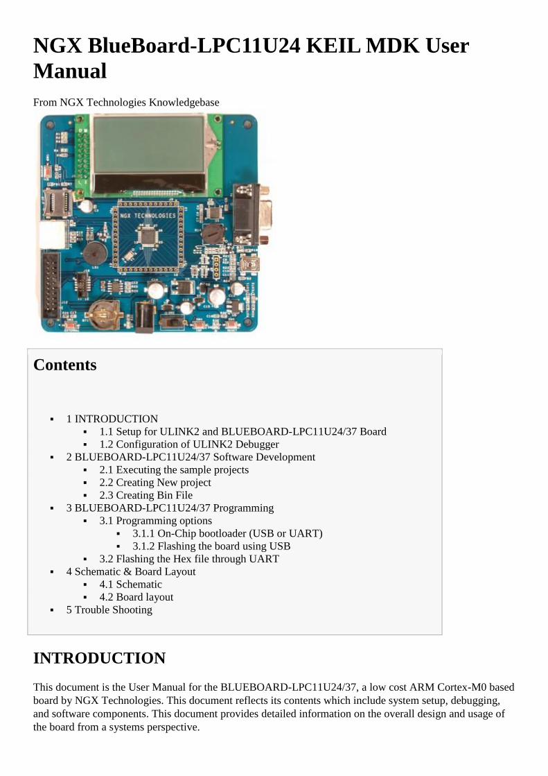
Step 2: Click on the settings option, the Cortex-M Target Driver Setup window opens then select SW port.
After selection of the SW port the ULINK2 detected is as shown in the image below
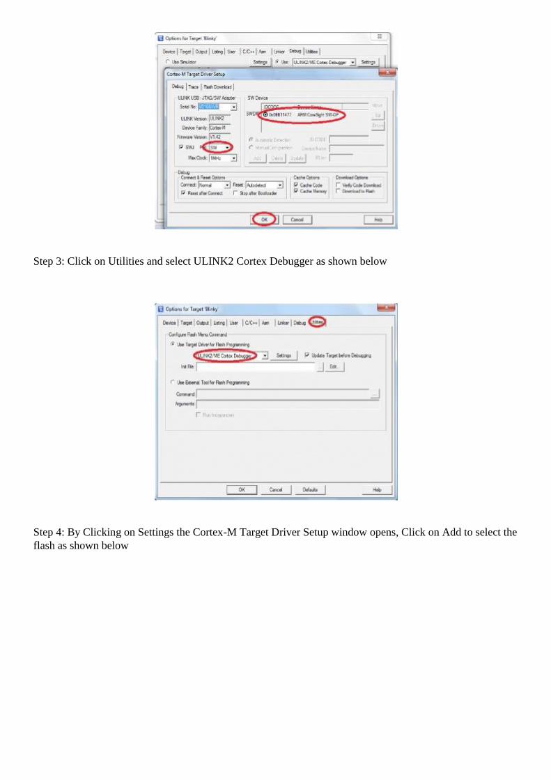
Step 3: Click on Utilities and select ULINK2 Cortex Debugger as shown below
Step 4: By Clicking on Settings the Cortex-M Target Driver Setup window opens, Click on Add to select the
flash as shown below

Click OK to complete the ULINK2 Debugger configuration
BLUEBOARD-LPC11U24/37 Software Development
Executing the sample projects
The sample projects are provided with the available kit.
Steps to execute the sample projects:
Step 1: Open the project folder.
Step 2: Then open the file project name.uvproj eg blinky.uvproj.
Step 3: This launches the IDE

Step 4: Click on Build to build the project as shown in the below image
Step 5: Click on Load to download as shown in the below image

Step 6: To debug the code click on Debug option then click on Start/Stop Debug session as shown in the
below image. Press F5 to free run or press F10 to line by line debug.
Creating New project
Follow the below steps, for creating new project:
Step 1: Open the keil IDE.

Step 2: Click on to the Project tab – new uvision project.
Step 3: Give project name then click Save.
Step 4: Select the controller.
Note: Both LPC11U24 and LPC11U37 are pin and binary compatible; we can select LPC11U24 device for
BB-LPC11U37.

Step 5: Go to file – new, & start writing the code.
Step 6: Save the file with some name.
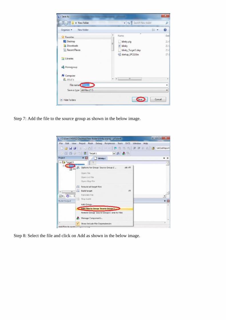
Step 7: Add the file to the source group as shown in the below image.
Step 8: Select the file and click on Add as shown in the below image.
Step 9: To build, download and debug follow the steps 4, 5 and 6 in section [3.1|#_3.1_Executing_the].
Creating Bin File
For creating bin file follow the below steps:
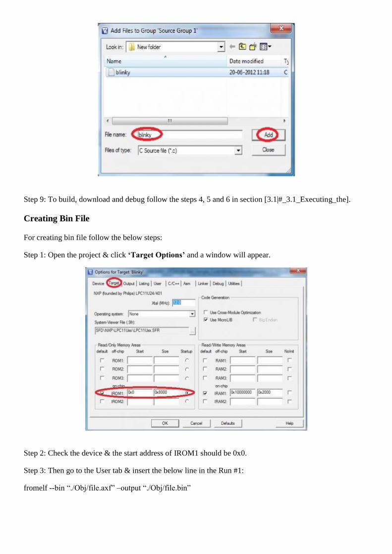
Step 1: Open the project & click ‘Target Options’ and a window will appear.
Step 2: Check the device & the start address of IROM1 should be 0x0.
Step 3: Then go to the User tab & insert the below line in the Run #1:
fromelf --bin “./Obj/file.axf” –output “./Obj/file.bin”

Step 4: Click on the Linker tab & select the „Use Memory Layout from Target Dialog‟, then click ok and
build the project, finally .bin file will be created.
Note: For newly built bin file you should update crc. Refer 6.0 Trouble Shooting for more details.
BLUEBOARD-LPC11U24/37 Programming
Programming options
BLUEBOARD-LPC11U24/37 can be programmed using the
On-chip bootloader (USB or UART)
Debugger (ULINK2)
On-Chip bootloader (USB or UART)

In order to program the board either through USB or UART we need to get the board under programming
mode.
Getting the board in programming mode:
Theory: The On-chip bootloader looks for a logic LOW to be present on a pre-defined PIN (ISP pin) during
reset. If the ISP pin is held LOW and reset signal is provided to the MCU, the MCU enters into
programming mode.
Practical:
On the BLUEBOARD-LPC11U24/37 the RESET and ISP signals are connected to buttons provided on the
board. Look for the RESET and ISP marking on the board. Therefore to enter into programming mode:
Press and hold the ISP button
Press the RESET button and release it
Now release the ISP button
The board is in the programming mode
We know that the on-chip bootloader can be used with USB or UART. Please note that if you have
connected a USB cable to the board the USB bootloader is activated else the UART bootloader is activated.
Meaning, if you have connected the USB cable as your power source then you cannot use UART
bootloader, you need to use an alternate external power source (DC jack) to enable UART bootloader. If a
particular MCU supports USB bootloading it is highly recommended to use the same for programming.
Programming through USB is the most convenient way to program the BlueBoard-LPC11U24. The
LPC11U24 has an on-chip USB bootloader support which makes programming the board very simple. You
don't require any PC application to program using USB bootloader. Once the board enters the programming
mode it appears as a drive on your Windows machine and all you need to do is just drag-n-drop your binary
to this drive.
Note: Not all NXP USB MCUs support USB boot loading. For example the LPC11U14 does not support
USB bootloader although it has support for USB on the chip.
Flashing the board using USB
The pre-build binaries can be used to flashing onto to the board for each peripheral by using the USB
bootloader as a Mass storage device. Press SW4, then SW5; release SW5, then SW4, the mass storage
device will appear on your screen. On the board LED D1 glows. Remove firmware.bin file and then place
your bin file and then press reset switch to execute the specific code written on to the flash.

Flashing the bin file (Drag & drop).
Note:For newly built bin file you should update crc. Refer 6.0 Trouble Shooting for more details.
Flashing the Hex file through UART
Step 1: Connect the serial cable to the PC as well as to the board UART0 and open the flash magic tool.
Step 2: Input all the parameters as shown in below Fig.

Step 3: Click *Star*t to flash the hex file. Press Reset to run.
NOTE: Make sure that the Board is not powered through USB.
Schematic & Board Layout
Schematic
This manual will be periodically updated, but for the latest documentations please check our website for the
latest documents. The Board schematic and sample code are available after the product has been registered
on our website.
Board layout

Trouble Shooting
For newly created bin file you should update crc.
Unfortunately, the checksum generated is not correct and unless the checksum of the .bin file is modified,
the firmware will be rejected by the USB bootloader. Thankfully, this is relatively easy to fix. There is free
utility to fix the checksum. A pre-compiled version for Windows (named lpcrc.exe) is also located in the
root folder. To fix the checksum, simply go into the command-line and go to the root folder where both the
lpcrc.exe tool and your .bin file are located (the file will be named 'firmware.bin' unless you have modified
the Makefile), and enter the following command:
Fixing the firmware.bin Checksum
lpcrc firmware.bin
Retrieved from "http://ngxtech.com/knowledgebase/index.php?title=NGX_BlueBoard-
LPC11U24_KEIL_MDK_User_Manual&oldid=6623"