nhp safety reference · pdf filedual channel interlocks suitable ... switching elements...
TRANSCRIPT

NHP S
AFET
Y REF
EREN
CE G
UIDE
Safety Switches
3. PRODUCTS
Features: Ordering details:
Technical data:
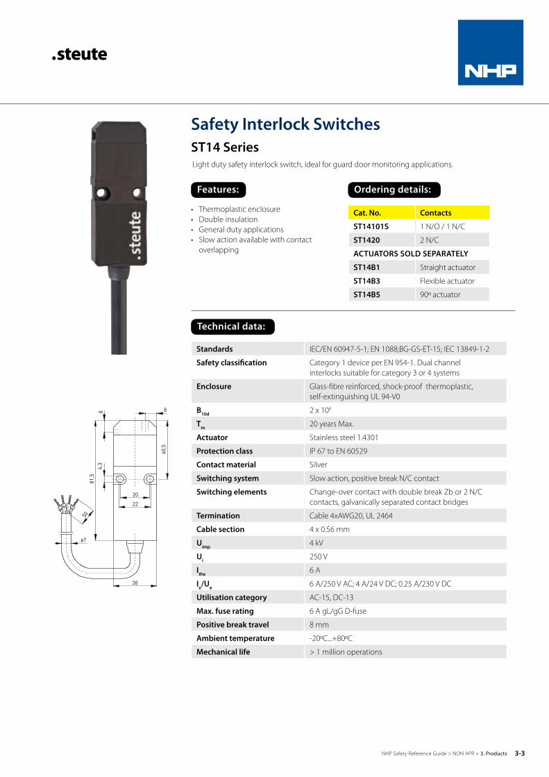
Standards IEC/EN 60947-5-1; EN 1088;BG-GS-ET-15; IEC 13849-1-2
Safety classification Category 1 device per EN 954-1. Dual channel interlocks suitable for category 3 or 4 systems
Enclosure Glass-fibre reinforced, shock-proof thermoplastic, self-extinguishing UL 94-V0
B10d 2 x 10⁶
Tm 20 years Max.
Actuator Stainless steel 1.4301
Protection class IP 67 to EN 60529
Contact material Silver
Switching system Slow action, positive break N/C contact
Switching elements Change-over contact with double break Zb or 2 N/C contacts, galvanically separated contact bridges
Termination Cable 4xAWG20, UL 2464
Cable section 4 x 0.56 mm
Uimp 4 kV
Ui 250 V
Ithe 6 A
Ie/Ue 6 A/250 V AC; 4 A/24 V DC; 0.25 A/230 V DC
Utilisation category AC-15, DC-13
Max. fuse rating 6 A gL/gG D-fuse
Positive break travel 8 mm
Ambient temperature -20ºC...+80ºC
Mechanical life > 1 million operations
Cat. No. Contacts
ST14101S 1 N/O / 1 N/C
ST1420 2 N/C
ACTUATORS SOLD SEPARATELY
ST14B1 Straight actuator
ST14B3 Flexible actuator
ST14B5 90º actuator
Safety Interlock SwitchesST14 SeriesLight duty safety interlock switch, ideal for guard door monitoring applications.
• Thermoplastic enclosure• Double insulation• General duty applications• Slow action available with contact
overlapping
3-3NHP Safety Reference Guide > NON APR > 3. Products

Features: Ordering details:
Safety Interlock SwitchesES95AZ SeriesGeneral duty safety interlock switch, ideal for guard door monitoring applications.
• Thermoplastic enclosure• General duty applications• Double insulation• Actuator heads can be repsitioned in
factory in 4 x 90º steps
Cat. No. Contacts
ES95AZ1O1S 1 N/O / 1 N/C
ES95AZ2O 2 N/C
ACTUATORS SOLD SEPARATELY
95AZB1 Straight actuator
95AZB5 90º actuator
Standards IEC/EN 60947-5-1; EN 1088 ; IEC 13849-1-2
Safety classification Category 1 device per EN 954-1. Dual channel interlocks suitable for category 3 or 4 systems
Enclosure Glass-fibre reinforced, shock-proof thermoplastic, self-extinguishing UL 94-V0
B10d 2 x 10⁶
Tm 20 years Max.
Actuator Stainless steel 1.4301
Protection class IP 67 to EN 60529
Contact material Silver
Switching system Slow action, positive break N/C contact
Switching elements Change-over contact with double break or 2 N/C contacts, galvanically separated contact bridges
Termination M3 screw terminals
Cable section Max. 1.5 mm2 (incl. conductor ferrules)
Uimp 4 kV
Ui 250 V
Ithe 6 A
Ie/Ue 6 A/400 V AC
Utilisation category AC-15, DC-13
Max. fuse rating 6 A gL/gG D-fuse
Positive break travel 9 mm
Ambient temperature -20ºC...+80ºC
Mechanical life > 1 million operations
Technical data:
ES95AZ
95AZB1
95AZB5
3-4NHP Safety Reference Guide > NON APR > 3. Products

Features: Ordering details:
Safety Interlock SwitchesST61 SeriesHeavy duty safety interlock switch, ideal for guard door monitoring applications.
• Metal enclosure• Heavy duty applications• Double insulation• 3 cable entries M20 x 1.5
Cat. No. Contacts
ST61101S 1 N/O / 1 N/C
ST612O 2 N/C
ACTUATORS SOLD SEPARATELY
ST61B1 Straight actuator
ST61B5 90º actuator
Standards IEC/EN 60947-5-1; EN 1088 ; IEC 13849-1-2
Safety classification Category 1 device per EN 954-1 Dual channel interlocks suitable for category 3 or 4 systems
B10d 2 x 10⁶
Tm 20 years Max.
Enclosure Aluminium die cast, paint finish
Actuator Stainless steel 1.4301
Protection class IP 65 to EN 60529
Contact material Silver
Switching system Slow action, positive break N/C contact
Switching elements Change-over contact with double break or 2 N/C contacts, galvanically separated contact bridges
Termination Plug-in connector
Cable section Max. 2.5 mm2 (incl. conductor ferrules)
Cable entry 3 x M20 x 1.5
Uimp 6 kV
Ie/Ue ES61: 16 A/400 V AC; ES61 2 N/C: 6 A/400 V AC
Utilisation category AC-15
Max. fuse rating ES 61: 16A gL/gG D-fuse; ES 61 2 N/C: 6 A gl/gG D-fuse
Positive break travel 10 mm
Ambient temperature -20ºC...+80ºC
Mechanical life > 1 million operations
Technical data:
3-5NHP Safety Reference Guide > NON APR > 3. Products

Features: Ordering details:
Standards IEC/EN 60947-5-1; EN 1088;BG-GS-ET-15 ; IEC 13849-1-2
Safety classification Category 1 device per EN 954-1 Dual channel interlocks suitable for category 3 or 4 systems
B10d 2 x 10⁶
Tm 20 years Max.
Enclosure Glass-fibre reinforced, shock-proof thermoplastic, self-extinguishing UL 94-VO
Actuator Stainless steel 1.4301
Protection class IP 67 to EN 60529
Contact material Silver
Switching system Slow action, positive break N/C contact
Switching elements Change-over contact with double break or 2 N/C contacts, galvanically separated contact bridges
Termination M3 screw terminals
Cable section Max. 1.5 mm2 (incl. conductor ferrules)
Uimp 4 kV
Ui 400 V
Ie/Ue 6 A/400 V AC; 0.25 A/230 V DC
Utilisation category AC-15, DC-13
Max. fuse rating 6 A gL/gG D-fuse
Positive break travel 8 mm
Ambient temperature -20ºC...+80ºC
Mechanical life > 1 million operations
Cat. No. Contacts
ES95T5C101S 1 N/O / 1 N/C
• Thermoplastic enclosure• Light duty applications• Double insulation• Actuator heads can be repositioned
in 4 x 90º steps
Technical data:
Safety Interlock SwitchesES95TC Series for hinged doorsLight duty safety interlock switch, ideal for hinged guard door monitoring applications.
3-6NHP Safety Reference Guide > NON APR > 3. Products

Features: Ordering details:
Safety Interlock SwitchesES13SB Series for hinged doorsLight duty safety interlock switch, ideal for hinged guard door monitoring applications.
Standards IEC/EN 60947-5-1; EN 1088;BG-GS-ET-15 ; IEC 13849-1-2
Safety classification Category 1 device per EN 954-1 Dual channel interlocks suitable for category 3 or 4 systems
B10d 2 x 10⁶
Tm 20 years Max.
Enclosure Glass-fibre reinforced, shock-proof thermoplastic, self- extinguishing UL 94-VO
Actuator Stainless steel 1.4301
Protection class IP 67 to EN 60529
Contact material Silver
Switching system Slow action, positive break N/C contact
Switching elements Change-over contact with double break Zb or 2 N/C contacts, galvanically seperated contact bridges
Termination Cable H05VV-F
Cable section 4 x 0.75 mm2
Uimp 4 kV
Ui 250 V
Ithe 6 A
Ie/Ue 6 A/250 V AC; 4 A/24 V DC
Utilisation category AC-15, DC-13
Max. fuse rating 6 A gL/gG D-fuse
Ambient temperature -20ºC...+80ºC
Mechanical life > 1 million operations
• Thermoplastic enclosure• Light duty applications• Double insulation• Standard 9.5 mm hollow diameter shaft
Cat. No. Contacts
ES13SB1O1S 1 N/O / 1 N/C
ES13SB2O 2 N/C
Technical data:
3-7NHP Safety Reference Guide > NON APR > 3. Products

Cat. No. Contacts
ES95SB101S 1 N/O / 1 N/C
ES95SB20 2 N/C
Features: Ordering details:
Safety Interlock SwitchesES95SB Series for Hinged DoorsGeneral duty safety interlock switch, ideal for hinged guard door monitoring applications.
Standards IEC/EN 60947-5-1; EN 1088; BG-GS-ET-15; IEC 13849-1-2
Safety classification Category 1 device per EN 954-1 Dual channel interlocks suitable for category 3 or 4 systems
B10d 2 x 10⁶
Tm 20 years Max.
Enclosure Glass-fibre reinforced, shock-proof thermoplastic, self-extinguishing UL 94-VO
Actuator Stainless steel 1.4301
Protection class IP 67 to EN 60529
Contact material Silver
Switching system Slow action, positive break N/C contact
Switching elements Change-over contact with double break Zb or 2 N/C contacts, galvanically seperated contact bridges
Termination M3 screw terminals
Cable section Max. 1.5 mm2 (incl. conductor ferrules)
Uimp 4 kV
Ui 400 V
Ithe 6 A
Ie/Ue 6 A/400 V AC; 0.25 A/230 V DC
Utilisation category AC-15, DC-13
Max. fuse rating 6 A gL/gG D-fuse
Ambient temperature -20ºC...+80ºC
Mechanical life > 1 million operations
• Thermoplastic enclosure• General duty applications• Double insulation• Standard 9.5 mm hollow diameter shaft
Technical data:
3-8NHP Safety Reference Guide > NON APR > 3. Products

Features: Ordering details:
Solenoid Interlock SwitchesSTM295 Series General duty safety solenoid interlock switch, ideal for guard door monitoring applications.
Standards IEC 13849-1-2;IEC/EN 60947-5-1;EN 1088;
Safety classification Category 1 device per EN 954-1 Dual channel interlocks suitable for category 3 or 4 systems
B10d 1 x 10⁶
Tm 20 years Max.
Enclosure Glass-fibre reinforced, shock-proof thermoplastic, self-extinguishing UL 94-VO
Actuator Stainless steel 1.4301
Protection class IP 67 to EN 60529
Contact material Silver
Switching system Slow action, positive break N/C contact
Switching elements 2 N/C and 2 N/O contacts with positive break, galvanically separated contact bridges
Termination M3 screw terminals
Cable section Max. 1.5 mm2 (incl. conductor ferrules)
Cable entries 2 x M20 x 1.5 for cable section 5 .... 9 mm
Uimp 4 kV
Ui 250 V
Ithe 4 A
Ie/Ue 4 A/250 V AC; 0.25 A/230 V DC
Utilisation category AC-15, DC-13
Power consumption Max. 47 W
Ambient temperature -20ºC... +55ºC
Mechanical life > 500,000 operations
Holding force F Max. 1000N
• Thermoplastic enclosure• General duty applications• Holding force of 1000N• Spring-to-lock and power-to-lock
models available
Cat. No. Contacts
STM2952O2SR Power-to-unlock
STM2952O2SA Power-to-lock
ACTUATORS SOLD SEPARATELY
STM295B1 Straight actuator
STM295B5 90º actuator
Technical data:
3-9NHP Safety Reference Guide > NON APR > 3. Products
Features: Ordering details:
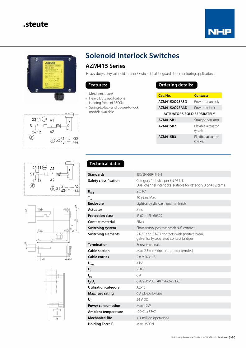
Solenoid Interlock SwitchesAZM415 SeriesHeavy duty safety solenoid interlock switch, ideal for guard door monitoring applications.
Standards IEC/EN 60947-5-1
Safety classification Category 1 device per EN 954-1. Dual channel interlocks suitable for category 3 or 4 systems
B10d 2 x 10⁶
Tm 10 years Max.
Enclosure Light-alloy die-cast, enamel finish
Actuator Zinc
Protection class IP 67 to EN 60529
Contact material Silver
Switching system Slow action, positive break N/C contact
Switching elements 2 N/C and 2 N/O contacts with positive break, galvanically separated contact bridges
Termination Screw terminals
Cable section Max. 2.5 mm2 (incl. conductor ferrules)
Cable entries 2 x M20 x 1.5
Uimp 4 kV
Ui 250 V
Ithe 6 A
Ie/Ue 6 A/250 V AC; 40 mA/24 V DC
Utilisation category AC-15
Max. fuse rating 6 A gL/gG D-fuse
Us 24 V DC
Power consumption Max. 12W
Ambient temperature -20ºC...+55ºC
Mechanical life > 1 million operations
Holding Force F Max. 3500N
Cat. No. Contacts
AZM4152O2SR3D Power-to-unlock
AZM4152O2SA3D Power-to-lock
ACTUATORS SOLD SEPARATELY
AZM415B1 Straight actuator
AZM415B2 Flexible actuator (y-axis)
AZM415B3 Flexible actuator (x-axis)
• Metal enclosure• Heavy Duty applications• Holding force of 3500N• Spring-to-lock and power-to-lock
models available
Technical data:
3-10NHP Safety Reference Guide > NON APR > 3. Products
Features: Ordering details:
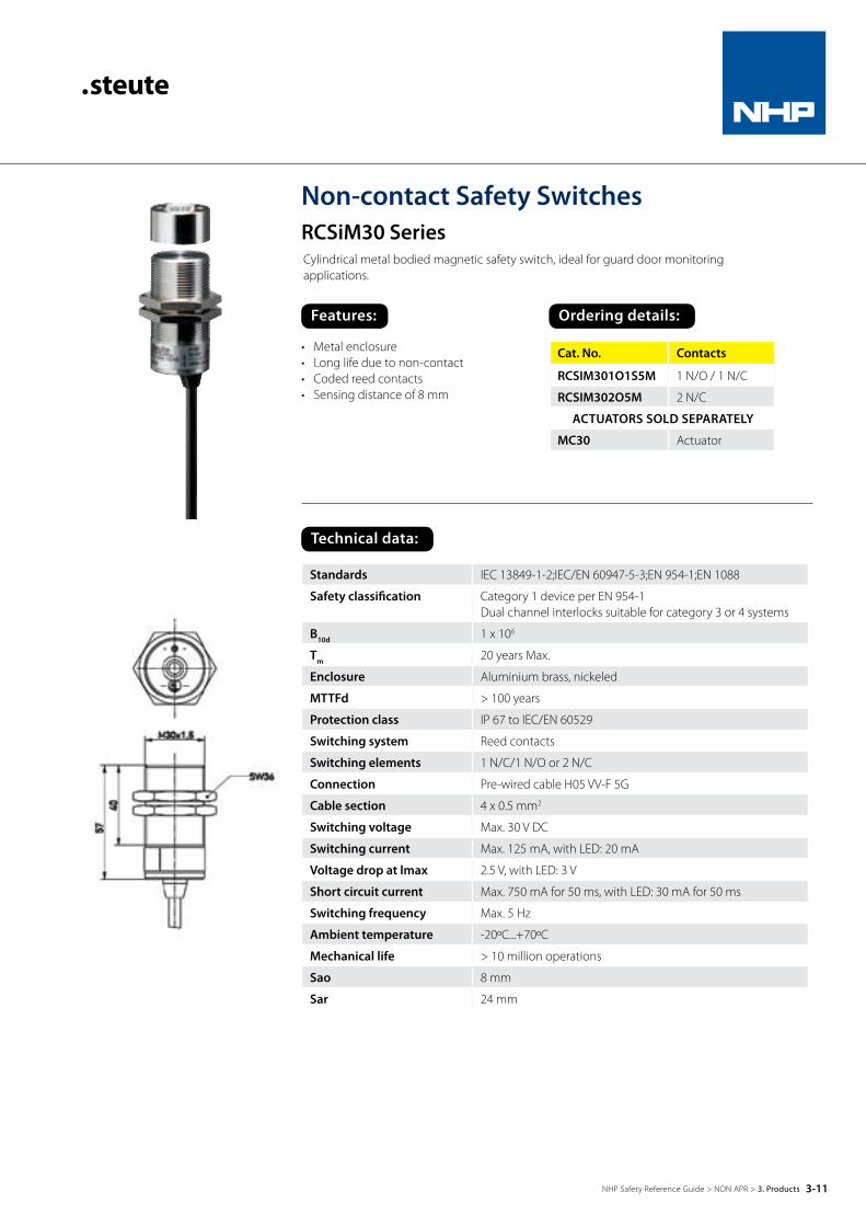
Non-contact Safety SwitchesRCSiM30 SeriesCylindrical metal bodied magnetic safety switch, ideal for guard door monitoring applications.
Cat. No. Contacts
RCSIM301O1S5M 1 N/O / 1 N/C
RCSIM302O5M 2 N/C
ACTUATORS SOLD SEPARATELY
MC30 Actuator
Standards IEC 13849-1-2;IEC/EN 60947-5-3;EN 954-1;EN 1088
Safety classification Category 1 device per EN 954-1 Dual channel interlocks suitable for category 3 or 4 systems
B10d 1 x 10⁶
Tm 20 years Max.
Enclosure Aluminium brass, nickeled
MTTFd > 100 years
Protection class IP 67 to IEC/EN 60529
Switching system Reed contacts
Switching elements 1 N/C/1 N/O or 2 N/C
Connection Pre-wired cable H05 VV-F 5G
Cable section 4 x 0.5 mm2
Switching voltage Max. 30 V DC
Switching current Max. 125 mA, with LED: 20 mA
Voltage drop at lmax 2.5 V, with LED: 3 V
Short circuit current Max. 750 mA for 50 ms, with LED: 30 mA for 50 ms
Switching frequency Max. 5 Hz
Ambient temperature -20ºC...+70ºC
Mechanical life > 10 million operations
Sao 8 mm
Sar 24 mm
• Metal enclosure• Long life due to non-contact• Coded reed contacts• Sensing distance of 8 mm
Technical data:
3-11NHP Safety Reference Guide > NON APR > 3. Products

Features: Ordering details:
Non-contact Safety SwitchesRCSi56 SeriesRectangular plastic bodied magnetic safety switch, ideal for guard door monitoring applications.
• Thermoplastic enclosure• Long life due to non-contact• Coded reed contacts• Sensing distance of 6 mm
Standards IEC 13849-1-2;IEC/EN 60947-5-3;EN 954-1;EN 1088
Safety classification Category 1 device per EN 954-1 Dual channel interlocks suitable for category 3 or 4 systems
B10d 2 x 10⁶
Tm 20 years Max.
MTTFd > 100 years
Enclosure Glass-fibre reinforced thermoplastic
Protection class IP 67 to IEC/EN 60529
Switching system Reed contacts
Switching elements 1 N/C/1 N/O or 2 N/C
Connection Pre-wired cable AWG 24
Cable section 4 x 0.5 mm2
Switching voltage Max. 30 V DC
Switching current Max. 157mA, with LED: 20 mA
Voltage drop at lmax 2.5 V, with LED: 3 V
Short circuit current Max. 750 mA for 50 ms, with LED: 30 mA for 50 ms
Switching frequency Max. 5 Hz
Ambient temperature -20ºC...+70ºC
Mechanical life > 10 million operations
Sao 4 mm
Sar 23 mm
Cat. No. Contacts
RCSI561O1S5M 1 N/O / 1 N/C
RCSI562O5M 2 N/C
ACTUATORS SOLD SEPARATELY
MC56 Actuator
Technical data:
RCSI5610155M
RCSI56205M
3-12NHP Safety Reference Guide > NON APR > 3. Products
Features: Ordering details:
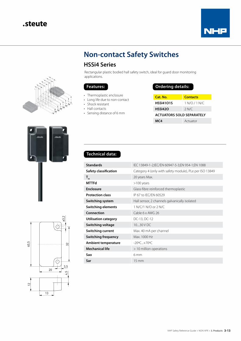
Non-contact Safety SwitchesHSSi4 SeriesRectangular plastic bodied hall safety switch, ideal for guard door monitoring applications.
• Thermoplastic enclosure• Long life due to non-contact• Shock resistant• Hall contacts• Sensing distance of 6 mm
Cat. No. Contacts
HSSI41O1S 1 N/O / 1 N/C
HSSI42O 2 N/C
ACTUATORS SOLD SEPARATELY
MC4 Actuator
Standards IEC 13849-1-2;IEC/EN 60947-5-3;EN 954-1;EN 1088
Safety classification Category 4 (only with safety module), PLe per ISO 13849
Tm 20 years Max.
MTTFd >100 years
Enclosure Glass-fibre reinforced thermoplastic
Protection class IP 67 to IEC/EN 60529
Switching system Hall sensor, 2 channels galvanically isolated
Switching elements 1 N/C/1 N/O or 2 N/C
Connection Cable 6 x AWG 26
Utilisation category DC-13, DC-12
Switching voltage 10....30 V DC
Switching current Max. 40 mA per channel
Switching frequency Max. 1000 Hz
Ambient temperature -20ºC...+70ºC
Mechanical life > 10 million operations
Sao 6 mm
Sar 15 mm
Technical data:
3-13NHP Safety Reference Guide > NON APR > 3. Products

Features: Ordering details:
Non-contact Safety SwitchesBZ16 SeriesRectangular plastic bodied hall safety switch with internal monitoring, ideal for guard door monitoring applications.
• Thermoplastic enclosure• Long life due to non-contact• Internal monitoring• Induction/hall contacts• Sensing distance of 10 mm
Standards IEC/EN 60947-5-3;EN 954-1;EN 1088
Safety classification Category 4 (only with Safety Module) per EN954-1, PLe per ISO 13849, SIL CL 3 per EN 62061
Tm 20 years Max.
MTTFd 57.8 years
PFHd 3 x 10⁻⁸
Enclosure Glass-fibre reinforced thermoplastic
Protection class IP 67 or IP 69K to IEC/EN 60529
Switching system Hall sensor
Switching elements 1 N/C/1 N/O or 2 N/C
Connection Terminal space with self opening terminals for max 2 x 1.5 mm2 (including conductor ferrules)
Cable entry 3 x M20 x 1.5
Uimp 24 V DC +/- 15%
Utilisation category AC-15, DC-13
Switching voltage Max. 250 V AC
Switching current Max. 4 A
Switching frequency Max. 1 Hz
Ambient temperature -20ºC...+55ºC
Sao 10 mm
Sar 20 mm
Cat. No. Contacts
BZ1611D (Front) 1 N/O / 1 N/C
BZ1602D (Front) 2 N/C
BZ1611V (Top) 1 N/O / 1 N/C
BZ1602V (Top) 2 N/C
ACTUATORS SOLD SEPARATELY
BZ16B1 Actuator
Technical data:
3-14NHP Safety Reference Guide > NON APR > 3. Products

Features: Ordering details:
Medium Duty Pullwire SwitchesTQZS70 Series
Cat. No. Contacts Contact action
TQZS701O1SVD 1 N/O + 1 N/C Snap
Kit: Contains:
TQZS70KIT10M 1 x TQZS701O1SVD (switch)1 x TQZSTS150N (spring)8 x TQZSWR5MM (cable)3 x 55150 (wire support)1 x 55164 (turnbuckle)4 x 55151 (thimble)8 x 55152 (wire clamp)
• Thermoplastic enclosure• Two contacts• Wire length up to 8 m• Release by pushbutton (VD) available• Wire pull and breakage function
Standards IEC 13849-1-2; IEC/EN 60947-5-1, IEC/EN 60947-5-5, EN 418
Cable entry 1 x M20 x 1.5
B10d 2 x 10⁶ Uimp 6 kV
TM 20 years Max. Ui 400 V
Enclosure Glass-fibre reinforced, shock-proof thermoplastic, ultramid
Ithe 6 A
Cover Glass-fibre reinforced, shock-proof thermoplastic, ultramid
Utilisation category
AC-15
Protection class IP 67 to IEC/EN 60529 Ie/Ue 6 A/400 V AC
Contact material Silver Max. fuse rating 6 A gL/gG D-fuse
Switching elements
Change-over contact withdouble break or 2 N/C contacts
Ambient temperature
–25ºC…+70ºC
Switching system Snap action, positive break N/C contacts
Mechanical life > 1 million operations
Connection Screw terminals Max. wire length 8 m
Cable section Max. 2.5 mm2 (incl. conductor ferrules)
Features Wire pull and breakage function
Technical data:
3-15NHP Safety Reference Guide > NON APR > 3. Products
3-16NHP Safety Reference Guide > NON APR > 3. Products
Features:
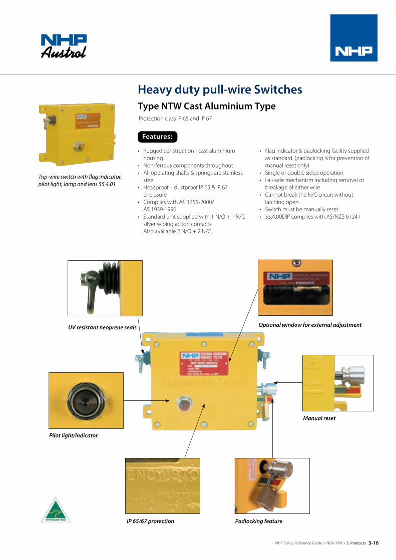
Heavy duty pull-wire SwitchesType NTW Cast Aluminium TypeProtection class IP 65 and IP 67
Trip-wire switch with flag indicator, pilot light, lamp and lens 55.4.01
Padlocking feature
Optional window for external adjustment
IP 65/67 protection
UV resistant neoprene seals
Manual reset
Pilot light/indicator
• Rugged construction - cast aluminium housing
• Non-ferrous components throughout• All operating shafts & springs are stainless
steel• Hoseproof – dustproof IP 65 & IP 67
enclosure• Complies with AS 1755-2000/
AS 1939-1990• Standard unit supplied with 1 N/O + 1 N/C
silver wiping action contacts. Also available 2 N/O + 2 N/C
• Flag indicator & padlocking facility supplied as standard. (padlocking is for prevention of manual reset only)
• Single or double sided operation• Fail-safe mechanism including removal or
breakage of either wire• Cannot break the N/C circuit without
latching open• Switch must be manually reset• 55.4.00DIP complies with AS/NZS 61241
3-17NHP Safety Reference Guide > NON APR > 3. Products
Features: Dimensions:
Ordering details:
Dust ignition proof (DIP) trip-wire switch:
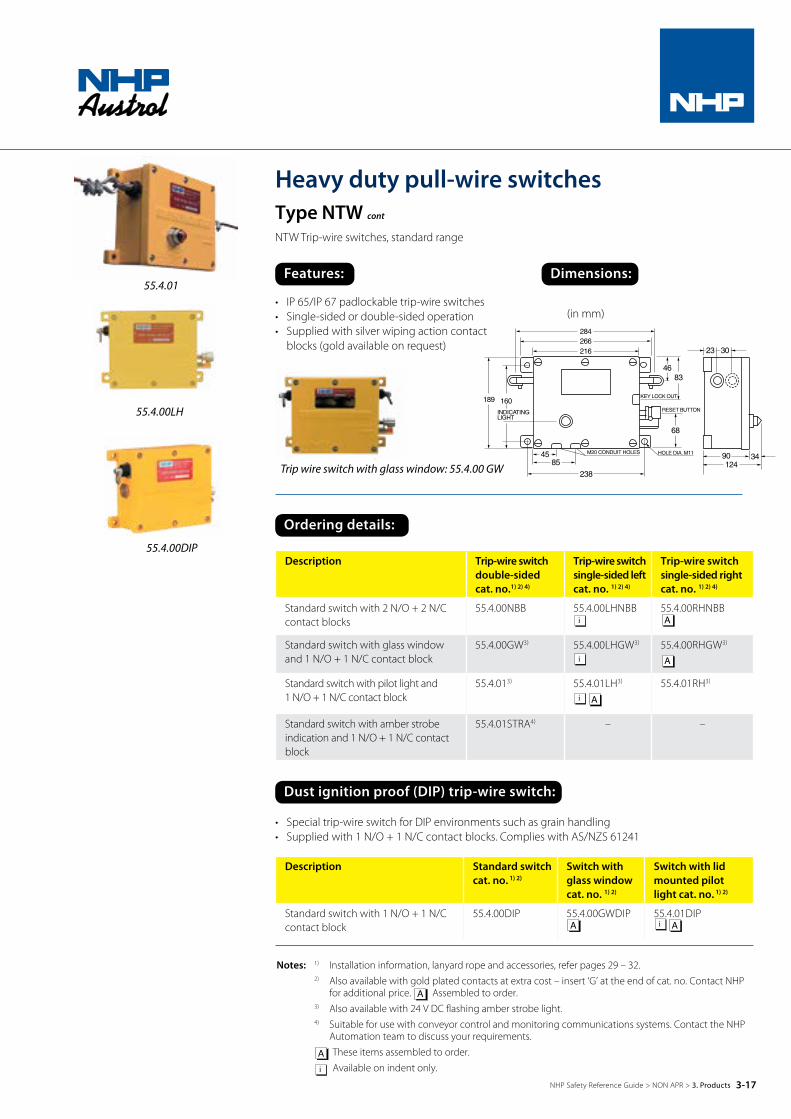
Heavy duty pull-wire switchesType NTW cont
NTW Trip-wire switches, standard range
Trip wire switch with glass window: 55.4.00 GW
55.4.00LH
55.4.01
55.4.00DIP
(in mm)
Notes: 1) Installation information, lanyard rope and accessories, refer pages 29 – 32. 2) Also available with gold plated contacts at extra cost – insert ‘G’ at the end of cat. no. Contact NHP
for additional price. A Assembled to order. 3) Also available with 24 V DC flashing amber strobe light. 4) Suitable for use with conveyor control and monitoring communications systems. Contact the NHP
Automation team to discuss your requirements. A These items assembled to order. i Available on indent only.
• IP 65/IP 67 padlockable trip-wire switches• Single-sided or double-sided operation• Supplied with silver wiping action contact
blocks (gold available on request)
• Special trip-wire switch for DIP environments such as grain handling• Supplied with 1 N/O + 1 N/C contact blocks. Complies with AS/NZS 61241
Description Trip-wire switchdouble-sidedcat. no.1) 2) 4)
Trip-wire switchsingle-sided leftcat. no. 1) 2) 4)
Trip-wire switchsingle-sided rightcat. no. 1) 2) 4)
Standard switch with 2 N/O + 2 N/C contact blocks
55.4.00NBB 55.4.00LHNBBi
55.4.00RHNBBA
Standard switch with glass window and 1 N/O + 1 N/C contact block
55.4.00GW3) 55.4.00LHGW3)
i55.4.00RHGW3)
A
Standard switch with pilot light and 1 N/O + 1 N/C contact block
55.4.013) 55.4.01LH3)
Ai
55.4.01RH3)
Standard switch with amber strobe indication and 1 N/O + 1 N/C contact block
55.4.01STRA4) – –
Description Standard switch cat. no. 1) 2)
Switch withglass windowcat. no. 1) 2)
Switch with lid mounted pilot light cat. no. 1) 2)
Standard switch with 1 N/O + 1 N/C contact block
55.4.00DIP 55.4.00GWDIPA
55.4.01DIPAi

3-18NHP Safety Reference Guide > NON APR > 3. Products
Lanyard accessories:
Spare contact blocks / Lamp block:
Spare Lamps SES style for Trip-wire Pilot light: 5) 6)
Spare parts:
55.1.50Wire support
55.1.52Wire clamp
2551 SES 110 V lamp
55.2.46Tension spring
55.1.51Thimble / sleeve
Notes: 1) 55.2.46 tension spring is only suitable for NTW 55.4 trip-wire switches. 2) Supplied complete with gasket 55.2.17. 3) Use with clip 55.2.40. 4) Eye/Eye turnbuckle available contact NHP. 5) Other voltages available contact NHP. 6) Stock brought in to order on some voltages. These items assembled to order.A
Heavy duty pull-wire switchesType NTW cont
Description Standard Cat. No. 316 grade stainless steel Cat. No.
‘D’ Shackle – 55.2.19NTW
Tension spring suits NTW 55.4 only 1) 55.2.46 55.2.46SS
Lanyard support bracket 55.1.50 55.1.50SS
5 mm thimble/sleeve 55.1.51 55.1.51SS
5 mm clamp/shackle 55.1.52 55.1.52SS
Turnbuckle hook and eye 10 mm x 145 mm 4) 55.1.64 55.1.64SS
Description Standard silver contact Cat. No.
Gold contactCat. No.
1 N/O + 1 N/C contacts NBAFP NBAG
2 N/O + 2 N/C contacts NBBFP NBBG
3 N/O + 3 N/C low voltage micro contact set and bracket - 554LVKIT
Lamp block for 55.4.01 (suit SES lamp) A
To suit Voltage SES Cat. No.
Full voltage pilot light 12 V 4 W No2243
Full voltage pilot light 24 V 4 W No2242
Resistor and full voltage pilot light 110 V 4 W No2551
Resistor and full voltage pilot light 260 V 4 W No2556
Description Cat. No.
Lid gasket 55.2.17
Shaft bellows 3) 55.2.37
Spare lid for 55.4.00 2) 55.2.16
Spare lid for 55.4.00GW 2) 55.2.16GW
Spare lid for 55.4.01 2) 55.2.16PL

3-19NHP Safety Reference Guide > NON APR > 3. Products
Lanyard Accessories:
Spare Contact Blocks / Lamp Block:
Spare Lamps SES Style for Trip-Wire Pilot Light: 5) 6)
Spare Parts:
55.1.50Wire support
55.1.52Wire clamp
2551 SES 110 V lamp
55.2.46Tension spring
55.1.51Thimble / sleeve
Notes: 1) 55.2.46 tension spring is only suitable for NTW 55.4 trip-wire switches. 2) Supplied complete with gasket 55.2.17. 3) Use with clip 55.2.40. 4) Eye/Eye turnbuckle available contact NHP. 5) Other voltages available contact NHP. 6) Stock brought in to order on some voltages. These items assembled to order.A
Heavy duty pull-wire switchesType NTW cont
Description Standard Cat. No.
316 grade stainless steel Cat. No.
‘D’ Shackle – 55.2.19NTW
Tension spring suits NTW 55.4 only 1) 55.2.46 55.2.46SS
Lanyard support bracket 55.1.50 55.1.50SS
5 mm thimble/sleeve 55.1.51 55.1.51SS
5 mm clamp/shackle 55.1.52 55.1.52SS
Turnbuckle hook and eye 10 mm x 145 mm 4) 55.1.64 55.1.64SS
Description Standard silver contact Cat. No.
Gold contactCat. No.
1 N/O + 1 N/C contacts NBAFP NBAG
2 N/O + 2 N/C contacts NBBFP NBBG
3 N/O + 3 N/C low voltage micro contact set and bracket - 554LVKIT
Lamp block for 55.4.01 (suit SES lamp) A
To suit Voltage SES Cat. No.
Full voltage pilot light 12 V 4 W No2243
Full voltage pilot light 24 V 4 W No2242
Resistor and full voltage pilot light 110 V 4 W No2551
Resistor and full voltage pilot light 260 V 4 W No2556
Description Cat. No.
Lid gasket 55.2.17
Shaft bellows 3) 55.2.37
Spare lid for 55.4.00 2) 55.2.16
Spare lid for 55.4.00GW 2) 55.2.16GW
Spare lid for 55.4.01 2) 55.2.16PL

3-20NHP Safety Reference Guide > NON APR > 3. Products
Accessories and spare parts:
Heavy duty pull-wire switchesType NTW cont
NTW trip-wire switches, standard range.
Lanyard rope / trip-wire• Developed to meet AS/NZS conveyor safety standard AS 1755-2000 these ropes are specially
tested to work in conjunction with the NHP/Austrol NTW 55.4 series trip wire switches
• Two types are available, i.e. PVC covered galvanised trip-wire, and the new NHP/Tufflex™ fibre lanyard rope
NHP/Tufflex™ fibre lanyard rope A unique combination of properties differentiates NHP/Tufflex™ fibre from other high-performance fibres and makes it the material of choice to meet performance requirements in demanding applications. The remarkable mechanical performance of NHP/Tufflex™ combined with the other unique properties, permit it to be used for a wide variety of purposes.
NHP/Tufflex™ unique fibres are used in aerospace, ocean exploration and development, electronic support structures, safety materials, industrial applications, composites, protective apparel and high-pressure inflatables.
NHP/Tufflex™ is a high-performance multi-filament yarn spun from liquid crystal polymer (LCP). It is the only commercially available melt-spun LCP fibre in the world exhibiting low weight and exceptional strength and rigidity. It is five times stronger than steel and ten times stronger than aluminium.
These unique properties characterise NHP/Tufflex™:
55.1.53P
55.1.53RLR
Description Cat. No.
Red PVC covered galvanised trip-wire Wire rope 7 mm dia. (4 mm wire coated in 3 mm RED UV resistant PVC)
Tripwire note: Standard role 200 metres. Cut lengths cannot be returned.
55.1.53P
LCP fibre lanyard rope NHP/Tufflex™ RED fibre lanyard rope 7 mm dia. (105 m roll)
55.1.53RLR
NHP/Tufflex™ RED fibre lanyard rope 7 mm dia. per metre (840 m roll) 55.1.53RLR-pm
Ordering details:
• High strength and modulus
• Low coefficient of thermal expansion (CTE)
• Excellent creep resistance
• High dielectric strength
• High abrasion resistance
• Outstanding cut resistance
• Excellent flex/fold characteristics
• Minimal moisture absorption
• Excellent property retention at high/ low temperatures
• Outstanding vibration damping characteristics
• Excellent chemical resistance
• High impact resistance

3-21NHP Safety Reference Guide > NON APR > 3. Products
Method of installation:
Heavy duty pull-wire switches cont
Type NTW cont Protection class IP 65 and IP 67
X Metres Max.
Turnbuckle Tension Spring
X Metres Max.
TurnbuckleTension Spring55.2.46 55.1.64
55.1.50
55.1.64 55.2.46
55.1.50Wire Supports
4.0 4.0
Wire Supports4.0 4.0
X Metres Max.
Turnbuckle Tension Spring
X Metres Max.
TurnbuckleTension Spring55.2.46 55.1.64
55.1.50
55.1.64 55.2.46
55.1.50Wire Supports
4.0 4.0
Wire Supports4.0 4.0
X Metres Max.
Turnbuckle Tension Spring
X Metres Max.
TurnbuckleTension Spring55.2.46 55.1.64
55.1.50
55.1.64 55.2.46
55.1.50Wire Supports
4.0 4.0
Wire Supports4.0 4.0
X Metres Max.
TurnbuckleTension Spring55.2.46 55.1.64
55.1.50Wire Supports
4.0 4.0
X Metres Max.
Turnbuckle Tension Spring
X Metres Max.
TurnbuckleTension Spring55.2.46 55.1.64
55.1.50
55.1.64 55.2.46
55.1.50Wire Supports
4.0 4.0
Wire Supports4.0 4.0
X Metres Max.
Turnbuckle Tension Spring
X Metres Max.
TurnbuckleTension Spring55.2.46 55.1.64
55.1.50
55.1.64 55.2.46
55.1.50Wire Supports
4.0 4.0
Wire Supports4.0 4.0
X Metres Max.
Turnbuckle Tension Spring
X Metres Max.
TurnbuckleTension Spring55.2.46 55.1.64
55.1.50
55.1.64 55.2.46
55.1.50Wire Supports
4.0 4.0
Wire Supports4.0 4.0
X Metres Max.
TurnbuckleTension Spring55.2.46 55.1.64
55.1.50Wire Supports
4.0 4.0
X Metres Max.
Turnbuckle Tension Spring
X Metres Max.
TurnbuckleTension Spring55.2.46 55.1.64
55.1.50
55.1.64 55.2.46
55.1.50Wire Supports
4.0 4.0
Wire Supports4.0 4.0
X Metres Max.
Turnbuckle Tension Spring
X Metres Max.
TurnbuckleTension Spring55.2.46 55.1.64
55.1.50
55.1.64 55.2.46
55.1.50Wire Supports
4.0 4.0
Wire Supports4.0 4.0
X Metres Max.
Turnbuckle Tension Spring
X Metres Max.
TurnbuckleTension Spring55.2.46 55.1.64
55.1.50
55.1.64 55.2.46
55.1.50Wire Supports
4.0 4.0
Wire Supports4.0 4.0
X Metres Max.
TurnbuckleTension Spring55.2.46 55.1.64
55.1.50Wire Supports
4.0 4.0
Single-sided operationTripwire/lanyard connected to one side of the trip-wire switch (either left or right) and terminated with a return compensation (tension) spring.
Double-sided operationTripwire/lanyard connected to both left and right hand sides of the trip-wire switch. Both left and right hand lanyards are terminated with a return compensation (tension) spring.
Multiple double-sided installationsFor longer conveyor runs, must be installed as shown below:
• Individual maximum lengths of lanyard (shown as ‘X’ in the diagrams above) in a horizontal plane must not exceed:
– 100 m when using NHP/Tufflex™ Lanyard rope (Cat. no. 55.1.53RLR) – 60 m when using NHP red PVC coated galvanised steel cable (Cat. no. 55.1.53P)
• NHP recommends the use of NHP/Tufflex™ as the lanyard when the conveyor system is operating over a 5 degree incline from the horizontal.
• NHP strongly recommends that pulleys are not used with the galvanised steel cable – i.e to curve the tripwire/lanyard around conveyor bends, and that pulleys only be used with NHP/Tufflex™ as the lanyard.

Heavy duty pull-wire switches cont
Type NTW cont
NTW trip-wire switches, standard range.
1. Firmly mount the trip-wire switch using the four mounting points on the trip-wire unit:
A. For double sided installation
• A maximum of 100 m from one end of the conveyor when using NHP/Tufflex™, or • A maximum of 60 m from one end of the conveyor when using NHP PVC coated galvanised
cable as the lanyard.
B. For single sided installation
• Mount the trip-wire switch at one end of the conveyor, ensuring that the maximum length of the tripwire/lanyard does not exceed: – 100 m when using NHP/Tufflex™ or, – 60 m when using NHP PVC coated galvanised wire as the lanyard.
Note: If either of the above distances are to be exceeded, then a double-sided installation must be used.
2. Fit the return compensation (tension) spring:
C. When using NHP/Tufflex™ as the lanyard:
• A maximum of 100 m from each side of the trip-wire switch for double-sided installations, or a maximum of 100 m from one side of the trip-wire switch for single-sided installations.
D. When using NHP PVC coated galvanised steel wire as the lanyard:
• A maximum of 60 m from each side of the trip-wire switch for double-sided installations, or a maximum of 60 m from one side of the trip-wire switch for single-sided installations.
3. Position lanyard wire supports at a maximum spacing of 4 m between the return compensation spring and the trip-wire switches. Smaller spacings will ensure higher performance of the trip-wire system.
4. Run the lanyard between the trip-wire switch and the return compensation springs.
5. Terminate the lanyard at the return compensation spring ends using thimbles and clamps. If using the PVC coated galvanised cable, remove outer PVC sheathing before clamping. Secure to the return compensation spring using ‘D’ shackle if necessary.
6. Unwind both ends of the turnbuckle/s to give maximum extension and hook one end to the shaft of the trip-wire switch using the provided ‘D’ shackle.
7. Terminate the other end of the lanyard to the turnbuckle/s using thimbles and clamps. If using the PVC coated galvanised cable, remove outer PVC sheathing before clamping. Before tightening clamp to lanyard, pull through all slack until taught, then tighten clamp.
8. Attach the external setting gauge/s using the screws provided, into the threaded holes, either above or below the external trip-wire switch shafts.
9. Adjust the turnbuckle/s until the end of the shaft is in-line with the end of the setting gauge.
10. Pull the lanyard numerous times to ‘bed-in’ the cable and remove any ‘deadband’ from the system. If necessary, re-adjust the turnbuckle until the end of the shaft is in-line with the end of the setting gauge. If desired, the setting gauge can now be removed.
11. The trip-wire switch set-up is now complete.
55.4.00 – open view
Schematic showing operating lever centred in the middle
of the operating cam.
Method of installation for single and double-Sided operation:
3-22NHP Safety Reference Guide > NON APR > 3. Products
Features: Ordering details:
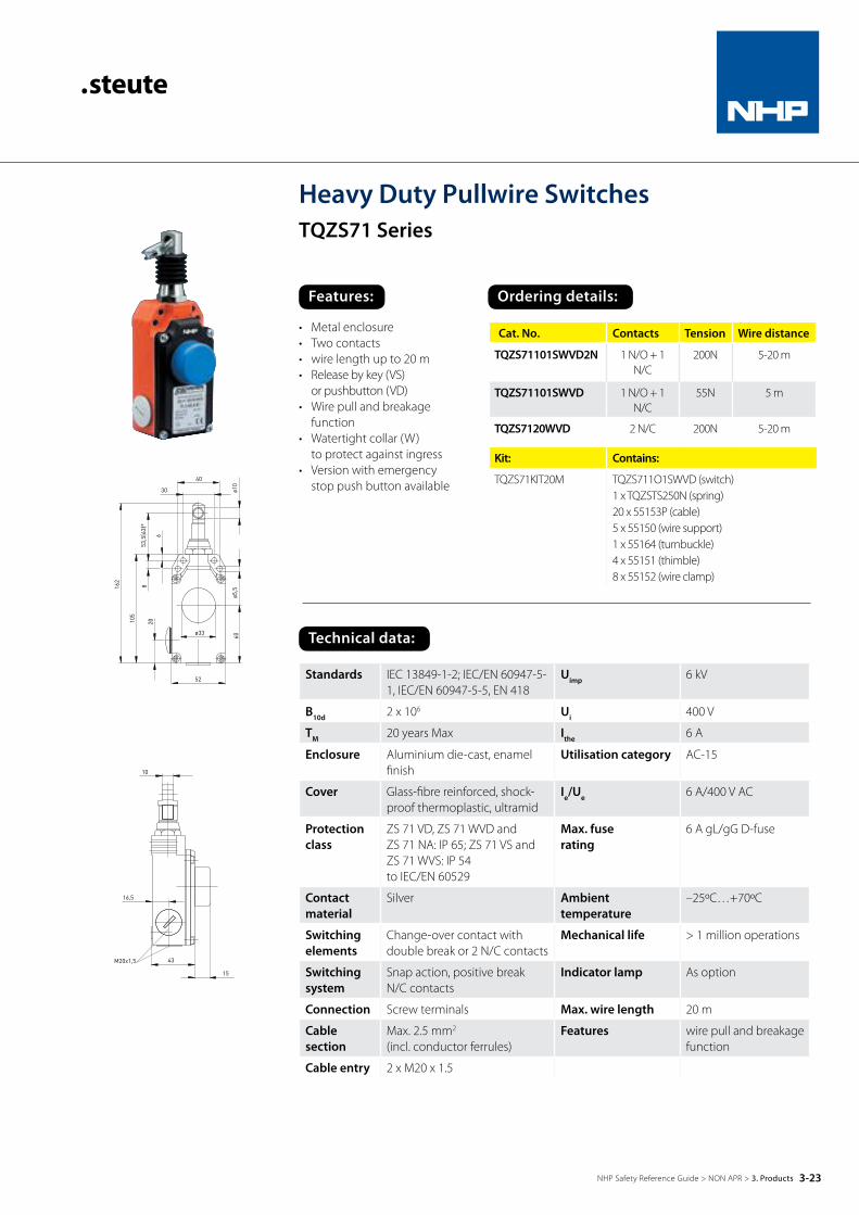
Heavy Duty Pullwire SwitchesTQZS71 Series
Cat. No. Contacts Tension Wire distance
TQZS71101SWVD2N 1 N/O + 1 N/C
200N 5-20 m
TQZS71101SWVD 1 N/O + 1 N/C
55N 5 m
TQZS7120WVD 2 N/C 200N 5-20 m
Kit: Contains:
TQZS71KIT20M TQZS711O1SWVD (switch)1 x TQZSTS250N (spring)20 x 55153P (cable)5 x 55150 (wire support)1 x 55164 (turnbuckle)4 x 55151 (thimble)8 x 55152 (wire clamp)
• Metal enclosure• Two contacts• wire length up to 20 m• Release by key (VS)
or pushbutton (VD)• Wire pull and breakage
function• Watertight collar (W)
to protect against ingress• Version with emergency
stop push button available
Standards IEC 13849-1-2; IEC/EN 60947-5-1, IEC/EN 60947-5-5, EN 418
Uimp 6 kV
B10d 2 x 10⁶ Ui 400 V
TM 20 years Max Ithe 6 A
Enclosure Aluminium die-cast, enamel finish
Utilisation category AC-15
Cover Glass-fibre reinforced, shock-proof thermoplastic, ultramid
Ie/Ue 6 A/400 V AC
Protection class
ZS 71 VD, ZS 71 WVD andZS 71 NA: IP 65; ZS 71 VS andZS 71 WVS: IP 54to IEC/EN 60529
Max. fuse rating
6 A gL/gG D-fuse
Contact material
Silver Ambient temperature
–25ºC…+70ºC
Switching elements
Change-over contact with double break or 2 N/C contacts
Mechanical life > 1 million operations
Switching system
Snap action, positive breakN/C contacts
Indicator lamp As option
Connection Screw terminals Max. wire length 20 m
Cable section
Max. 2.5 mm2
(incl. conductor ferrules)Features wire pull and breakage
function
Cable entry 2 x M20 x 1.5
Technical data:
3-23NHP Safety Reference Guide > NON APR > 3. Products

Features: Ordering details:
Heavy Duty Pullwire SwitchesTQZS73 Series
Cat. No. Contacts Contact action
TQZS731O1SWVD 1 N/O + 1 N/C Snap
TQZS7320WVD 2 N/C Snap
Kit: Contains:
TQZS73KIT50M TQZS731O1SWVD (switch)1 x TQZSTS250N (spring)50 x 55153P (cable)10 x 55150 (wire support)1 x 55164 (turnbuckle)4 x 55151 (thimble)8 x 55152 (wire clamp)
• Metal enclosure• Two contacts• Wire length up to 50 m• Release by key (VS) or pushbutton (VD)• Wire pull and breakage function• Watertight collar (W) to protect
against ingress
Standards IEC/EN 60947-5-1 Termination Screw terminals
B10d 2 x 10⁶ Cable section Max. 2.5 mm2 (incl. conductor ferrules)
Tm 20 years Max. Cable entry 1 x M20 x 1.5
Enclosure Aluminium die-cast, enamel finish Uimp 6 kV
Cover Glass-fibre reinforced, shockproof thermoplastic, ultramid
U i 400 V
Protection class
ZS 73 SR VD: IP 65 ZS 73 SR VS: IP54 to IEC/EN 60529
Ithe 6 A
Contact material
Silver Utilisation category
AC-15
Switching elements
Change-over contact with double break or 2 N/C contacts
Ie/Ue 6 A/400 V AC
Switching system
Snap action, positive break N/C contacts
Technical data:
3-24NHP Safety Reference Guide > NON APR > 3. Products
Features: Ordering details:
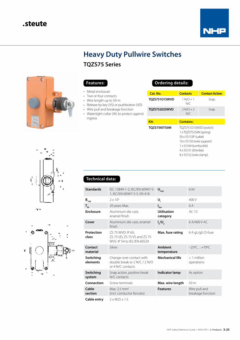
Heavy Duty Pullwire SwitchesTQZS75 Series
Cat. No. Contacts Contact Action
TQZS751O1SWVD 1 N/O + 1 N/C
Snap
TQZS75202SWVD 2 N/O + 2 N/C
Snap
Kit: Contains:
TQZS75KIT50M TQZS751O1SWVD (switch)1 x TQZSTS250N (spring)50 x 55153P (cable)10 x 55150 (wire support)1 x 55164 (turnbuckle)4 x 55151 (thimble)8 x 55152 (wire clamp)
• Metal enclosure• Two or four contacts• Wire length up to 50 m• Release by key (VS) or pushbutton (VD)• Wire pull and breakage function• Watertight collar (W) to protect against
ingress
Standards IEC 13849-1-2; IEC/EN 60947-5-1, IEC/EN 60947-5-5, EN 418
Uimp 6 kV
B10d 2 x 10⁶ Ui 400 V
TM 20 years Max. Ithe 6 A
Enclosure Aluminium die-cast, enamel finish
Utilisation category
AC-15
Cover Aluminium die-cast, enamel finish
Ie/Ue 6 A/400 V AC
Protection class
ZS 75 WVD: IP 65;ZS 75 VD, ZS 75 VS and ZS 75 WVS: IP 54 to IEC/EN 60529
Max. fuse rating 6 A gL/gG D-fuse
Contact material
Silver Ambient temperature
–25ºC…+70ºC
Switching elements
Change-over contact with double break or 2 N/C / 2 N/O or 4 N/C contacts
Mechanical life > 1 million operations
Switching system
Snap action, positive break N/C contacts
Indicator lamp As option
Connection Screw terminals Max. wire length 50 m
Cable section
Max. 2.5 mm2
(incl. conductor ferrules)Features Wire pull and
breakage function
Cable entry 2 x M25 x 1.5
Technical data:
3-25NHP Safety Reference Guide > NON APR > 3. Products

Features: Ordering details:
Cat. No. Contacts Contact action
TQZS802O2SWVD 2 N/O + 2 N/C Snap
TQZS803O1SWVD 1 N/O + 3 N/C Snap
Kit: Contains:
TQZS80KIT50M TQZS802O2SWVD (switch)1 x TQZSTS250N (spring)50 x 55153P (cable)1 x 55150 (wire support)1 x 55164 (turnbuckle)4 x 55151 (thimble)8 x 55152 (wire clamp)
• Metal enclosure• Four contacts• Position indicator and intergrated
emergency-stop push button• Wire legnth up to 75 m• Pretensioning force 100N• Lever for release and position indication• Watertight (W) collar• Wire pull and breakage function
Standards IEC 13849-1-2; IEC/EN 60947-5-1, IEC/EN 60947-5-5, EN 418
Uimp 2.5 kV
B10d 2 x 10⁶ Ui 250 V
TM 20 years Max. Ithe 2 A
Enclosure Aluminium die-cast, enamel finish
Utilisation cat-egory
AC-15
Cover Glass-fibre reinforced, shock-proof thermoplastic, ultramid
Ie/Ue 2 A/250 V AC
Protection class IP 67 to IEC/EN 60259 Max. fuse rating 2 A gL/gG D-fuse
Switching elements 2 N/C/2 N/O, 3 N/C/1 N/O or 4 N/C contacts with double break
Ambient temperature
–20ºC…+70ºC
Switching system Slow action, positive break N/C contacts
Mechanical life > 100,000 operations
Connection 2 x 4 pole terminal block Indicator lamp As option
Cable section Max. 2.5 mm2 (incl. conductor ferrules)
Max. wire length 75 m
Cable entry 3 x M20 x 1.5 Features Wire pull and breakage function
69
23 42
40 48
¤ 1 2
53
83
66 93
, 5
M20x1,5
67
14 0
M20x1,5
12
¤ 6 ,5 10 7, 5
1
69
23 42
40 48
¤ 1 2
53
83
66 93
, 5
M20x1,5
67
14 0
M20x1,5
12
¤ 6 ,5 10 7, 5
1
Heavy Duty Pullwire SwitchesTQZS80 Series
Technical data:
3-26NHP Safety Reference Guide > NON APR > 3. Products

Features: Ordering details:
Heavy Duty Belt Drift SwitchesZS 73 SR Series
Cat. No. Contacts Contact action
ZS73SR1O1S* 1 N/O + 1 N/C Snap
ZS73SR1O1SVD 1 N/O + 1 N/C Snap (push button reset)
* = Spring return lever
• Metal enclosure• Two contacts• Release by push button (VD)
or spring return possible• Belt alignment roller stainless steel• Stainless steel roller available seperately• Other contact variants available i.e. 2 N/C
Standards IEC/EN 60947-5-1 Cable entry 2 x M20 x 1,5
B10d ZS 73 SR – 2 x 10⁻⁶ ZS73 SR VD – 200,000
Uimp 6 kV
Tm 20 years Max. Ui 400 V
Enclosure Aluminium die-cast, enamel finish Ithe 6 A
Cover Glass-fibre reinforced, shockproof thermoplastic, ultramid
Utilisation category
AC-15
Protection class
ZS 73 SR VD: IP 65ZS 73 SR VS: IP 54to IEC/EN 60529
Ie/Ue 6 A/400 V AC
Contact material
Silver Max. fuse rating
6 A gL/gG D-fuse
Switching elements
Change-over contact with double break or 2 N/C contacts
Ambient temperature
–25ºC…+70ºC
Switching system
Snap action, positive break N/C contacts
Mechanical life
> 1 million operations
Connection Screw terminals max. 2.5 mm2
(incl. conductor ferrules)Indicator lamp as option
Technical data:
3-27NHP Safety Reference Guide > NON APR > 3. Products

Features: Ordering details:
Heavy Duty Belt Drift SwitchesZS 75 SR Series
Cat. No. Contacts Contact action
ZS75SR1O1S 1 N/O + 1 N/C Snap
ZS75SR1O1SVD (pushbutton reset)
1 N/O + 1 N/C Snap
ZS75SR2O2S 2 N/O + 2 N/C Snap
ZS75SR2O2SVD (pushbutton reset)
2 N/O + 2 N/C Snap
• Metal enclosure• Two or four contacts• Release by pushbutton (VD)
or spring return• Stainless steel belt alignment roller • Roller arm available as spare• Other contact variants available
Standards IEC/EN 60947-5-1 Cable entry 2 x M25 x 1.5
B10d ZS 75 SRVD – 200,000 ZS 75 SR – 2 x 10⁻⁶
Uimp 6 kV
Tm 20 years Max. Ui 400 V
Enclosure Aluminium die-cast, enamel finish Ithe 6 A
Cover Aluminium die-cast, enamel finish Utilisation category
AC-15
Protection class
ZS 75 SR VD: IP 65ZS 75 SR VS: IP 54to IEC/EN 60529
Ie/Ue 6 A/400 V AC
Contact material
Silver Max. fuse rating
6 A gL/gG D-fuse
Switching elements
Change-over contact with double break or 2 N/O / 2 N/C or 4 N/C
Ambient temperature
–25ºC…+70ºC
Switching system
Snap action, positive breakN/C contacts
Mechanical life
> 1 million operations
Connection Screw terminals Indicator lamp as option
Cable section
Max. 2.5 mm2
(incl. conductor ferrules)
Technical data:
3-28NHP Safety Reference Guide > NON APR > 3. Products

Features: Ordering details:
Extreme Duty Belt Drift SwitchesZS91 Series
Cat. No. Contacts
ZS91-SR-1OS1OS-40C85C-X 1 N/O / 1 N/C
ZS91-SR-4O2S-VD-40C85C-X 2 N/O / 4 N/C
• Operating temperature range from -40ºC• Glass-fibre reinforced, shock-proof
thermoplastic• 4 or 6 contact versions available
Standards EN ISO 13849-1; EN 60947-5-1
B10d (10 % Load) ZS 91 SR VD: 80 000,Ex ZS 91 SR: 2 million
Enclosureglass-fibre reinforced, shock-proof thermoplastic, UV resistant to EN ISO 4892
TM max. 20 years
Coverglass-fibre reinforced, shock-proof thermoplastic, UV resistant to EN ISO 4892
Uimp 6 kV
Degree of protection IP 66/67 to IEC/EN 60529 Ui 400 V
Contact material Silver Ithe 6:00 AM
Switching ele-ments
3 NC/3 NO contacts or4 NC/2 NO contacts or2 NC/2 NO contacts or3 NC/1 NO contacts or4 NC contacts with double break
Utilisation category AC-15
Switching system
snap action, positive breakNC contacts Ie/Ue 6 A/400 V AC
Connection Screw connection terminals Max. fuse rating 6 A gG/gN fuse
Cable Cross-Section
max. 2.5 mm²(incl. conductor ferrules)
Ambient temperature –40 °C … +85 °C
Cable entry 2 x M25 x 1.5 Mechanical life
ZS 91 SR VD:> 40 000 operations;ZS 91 SR: > 1 million operations
Technical data:0°30°
21-22
21-22
13-14
13-14B
A
15° 30°15°
25° 25°
23
0
40
ø4
0
152
285,5
34,5
91
11,5
20
0
17
6
M25x1,5
23
0
40
ø4
0
152
285,5
34,5
91
11,5
20
0
17
6
M25x1,5
3-29NHP Safety Reference Guide > NON APR > 3. Products

Plunger actuator
Roller plunger actuator
Offset plungerCat whisker Spring rod
Safety Limit SwitchesES95 SeriesOther Features / Options available: Gold-plated contacts, mechanical lockings with release by means of a pushbutton.
Features: Ordering details:
Cat. No. Contacts Contact action
Actuator
ES95W1O1S 1 N/O / 1 N/C Slow Plunger
ES95R1O1S 1 N/O / 1 N/C Slow RollerPlunger
ES954K1O1S 1 N/O / 1 N/C Slow OffsetPlunger
ES95D1O1S 1 N/O / 1 N/C Slow RollerLever
ES95DS1O1S 1 N/O / 1 N/C Slow Adj. lever
ES95DD1O1S 1 N/O / 1 N/C Slow Rod
ES95TL1O1S 1 N/O / 1 N/C Slow CatWhisker
ES95TK1O1S 1 N/O / 1 N/C Slow SpringRod
• Thermoplastic enclosure• Double insulated• Slow action with overlapping
contacts available• Wide range of alternative
actuators• Actuator heads can be
repositioned 4 x 90° steps• One cable entry M20 x 1.5
3-30NHP Safety Reference Guide > NON APR > 3. Products

Safety Limit Switches cont
ES95 SeriesOther features / options available: Gold-plated contacts, mechanical lockings with release by means of a pushbutton.
Standards IEC/EN 60947-5-1; EN 1088; BG-GS-ET-15
B10d 2 x 10⁶
Tm 20 years Max.
Class DIN EN 50 047
Enclosure Thermoplastic
Protection class IP 67 to IEC/EN 60529
Contact material Silver
Switching system IEC 60947-5-1 snap action, or slow action positive break N/C contacts
Cable section Max. 2.5 mm2 (incl. conductor ferrules)
Cable entry 2 x M25 x 1.5
Uimp 4 kV
Ui 400 V
Ithe 6 A
Utilisation category AC-15, DC-13
Ie/Ue 6 A/400 V AC; 0,25 A/230 V DC
Max. fuse rating 6 A gL/gG D-fuse
Mechanical life > 1 million operations
Switching frequency 1800/h
Ambient temperature –20ºC…+80ºC
Contact opening 2 x 3.5 mm
Approvals * Other contact variants available
Technical data:
Roller lever
Adj. lever
Rod
3-31NHP Safety Reference Guide > NON APR > 3. Products

Features: Ordering details:
Cat. No. Contacts Contact action
ES41 1 N/O / 1 N/C Slow
ES41R1O1S 1 N/O / 1 N/C Slow
ES41D1O1S 1 N/O / 1 N/C Slow
ES41DS1O1S 1 N/O / 1 N/C Slow
ES41TL1O1S 1 N/O / 1 N/C Slow
• Metal enclosure• Slow action change over contact
or 2 N/C contacts with double-break• Slow action with overlapping
contacts available• Three cable entries M16 x 1.5• Available with mechanical locking• For temperatures up to 180ºC
available on request• Positive break for slow action
Standards IEC 13849-1-2; IEC/EN 60947-5-1
Ui 400 V
Enclosure Aluminium die cast, paint finish
Ithe 6 A
Protection class
IP 65 to IEC/EN 60529 Utilisation category
AC-15
Contact material
Silver Ie/Ue 6 A/400 V AC
Switching elements
Change-over contact with double break or 2 N/C contacts, galvanically separated contact bridges
Max. fuse rating 6 A gL/gG D-fuse
Switching system
Slow action, positive break N/C contacts IEC 60947-5-1
Mechanical life > 1 million operations
Cable section
Max. 2.5 mm2
(incl. conductor ferrules)Switching frequency
3600/h
Cable entry 3 x M 16 x 1.5 Ambient temperature
–20ºC…+80ºC
Uimp 4 kV Repeat accuracy of switching points
±0.1 mm
Technical data:
Safety Limit SwitchesES41 Series
ES/EM4101S
ES/EM41R101S
ES/EM41D101S
ES/EM41DS101S
EM41TL101S
3-32NHP Safety Reference Guide > NON APR > 3. Products

features: ordering details:
Safety FootswitchesGFSVD seriesFoot switches with positive break.
• Metal enclosure• 1 or 2 pedal versions• Max. 4 contacts per pedal
Cat. No. Description Contacts
GFS2SD20VD Single Pedal Version
2 N/O / 2 N/C
Standards EN ISO 13849-1; EN 60947-5-1, BG-GS-ET-15
Enclosure Aluminium die-cast, enamel finish,RAL 5011
Pedal glass-fibre reinforced thermoplastic
Protective shield Aluminium die-cast, enamel finish,RAL 5011
Connection Screw connection terminals
Cable cross-section Max. 2.5 mm² (incl. conductor ferrules)
Cable entry 1 x M20 x 1.5
Contact material Silver
Degree of protection IP 65 to IEC/EN 60529
Switching system Slow action with double break, positive break NC contacts
Switch insert ES 60 GF VD, ES 60 GF IK VD
Switching elements 1 NO/1 NC or 2 NO/2 NC contacts
Actuating force Approx. 240 N
B10d (10 % Load) 200 000
TM Max. 20 years
Utilisation category AC-15
Uimp 6 kV
Ui 500 V
Ithe GFS VD: 16 A, GFS IK VD: 6 A
Ie/Ue GFS VD: 16 A/400 V AC, GFS IK VD: 6 A/400 V AC
Contact load capacitiy Max. 400 V AC, GFS VD: max. 16 A (cos φ = 1), GFS IK VD: Max. 6 A (cos φ = 1)
Max. fuse rating GFS VD: 16 A gG/gN fuse, GFS IK VD: 6 A gG/gN fuse
Ambient temperature –25 °C … +80 °C
Mechanical life > 100 000 operations
Approvals DGUV; CSA; PCT; CCC
Technical Data:
3-33NHP Safety Reference Guide > NON APR > 3. Products