ni-yantra 2016 progress...
TRANSCRIPT
NI-YANTRA 2016 Progress Report
Team ID: NIY – 93
Project Title: SAPER – A Semi-Autonomous Pipeline Exploration Robot
Team Members:
Rohit Kashyap – Vivekanand Education Society’s Institute of Technology.
Rahul Kashyap – K. J. Somaiya College of Engineering.
1. Description
Pipelines have been an integral part of our constructions since ages. Though accounted to high initial
costs they have been widely employed in major utilities and provide the most convenient mode of
transportation for portable water, sewage, potentially dangerous and inflammable petroleum products, natural
gas, etc. Thus, large networks of pipelines exist throughout the nation for transportation of the above
mentioned materials.
As per figures, the world’s largest underground network of pipeline was constructed by GAIL (Gas
Authority of India Limited) and is about 1,750 km long. Its primary purpose is to transport gas and carries
about 18 million cubic metres of gas to power three power houses and six fertilizer plants. Oil, gas and water
pipelines are presumed to be of foremost significance in the context of this article.
Amidst the tall buildings in metropolitan cities exists a network of ducts and underground pipelines
that carries its drinking water, sewage, medical and industrial waste, etc. Each of it is under a constant threat
from corrosion, cracks, leaks, clogs & other countless hazards. Cracks & leaks in water pipelines can lead to
the loss of a tremendous amount of useful water while that in gas pipelines to deadly explosions.
The sizes of such pipes, location and its large network, makes inspection difficult & is thus not done
on a regular basis. Human inspection of each is also potentially dangerous as these pipelines with time become
a storehouse of toxic & deadly fumes like methane and nitrogen. The test techniques available like candle test
for the presence of such trapped gases too is not quite state of the art. All of the above mentioned facts are a
testimonial of the miserable condition of the existing pipelines.
The aim of this project is to propose and design a robot that can help municipalities identify the
problems in the existing network of ducts and pipelines before they can lead to disasters like floods,
contaminated drinking water, health hazards, etc.
2. Existing Monitoring Technologies & Robots
Most of the pipelines are underground and thus pretty inaccessible to humans. However, frequent
monitoring of these pipelines is essential to keep them functional and to prevent any upcoming disaster. At
present, monitoring technologies include acquisition and analysis of images via satellites, radio images, UAV
based systems, etc. The Brihanmumbai Municipal Corporation (BMC), Maharashtra, sends its ‘sounding
mukadams’ with a sounding rods to detect leakages in water pipes situated below road networks. All of these
out-pipe monitoring technologies have their own drawbacks like satellites are unable to provide efficient
images under cloudy conditions, the distances that UAV’s can cover, etc.
Robots have also been employed for in-pipe inspection thus giving information of internal clogging,
blockages, etc. KANTARO, KURT, KARO, etc. are few examples of in-pipe inspection robots. The pipeline
exploration robots existing today can easily traverse through horizontal pipes but need plenty of expensive
modifications to traverse into vertical pipes. Pig type, wheels based, caterpillar, wall-press, inchworm, screw
type are the common in-pipe inspection robots.
The main objective while designing SAPER was to have a robot that could easily manoeuvre through
any pipeline structure like 45° & 90° elbows, T & Y-branches, etc. To do so, SAPER should have a very good
grip on the walls of the pipeline. Also, SAPER must be able to exert adequate force on the walls of the pipe
to prevent it from falling down while traversing across vertical and other pipe structures.
To achieve these features, SAPER’s first basic structure was prototyped to utilise both Caterpillar and
Wall-press type robot’s characteristics.
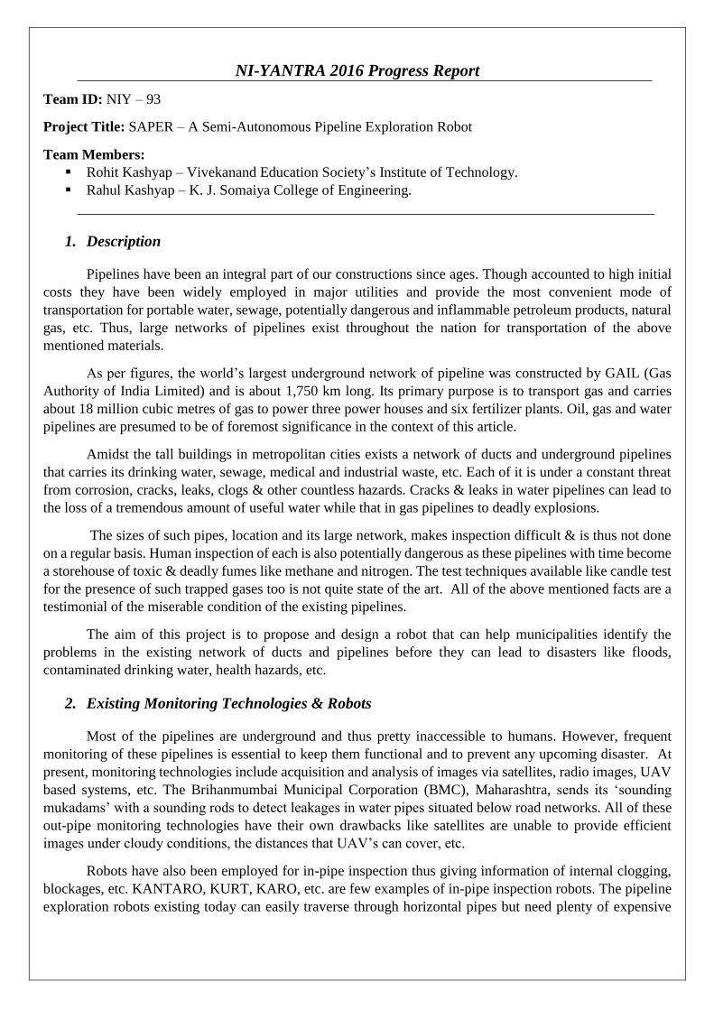
3. SAPER’s Mechanical Design
SAPER's Design in SOLIDWORKS & Final Assembly
SAPER is an in-pipe inspection robot. The initial design was prototyped to work in 6-inch pipelines
with dimensions of 18*15*15 cm. The thing of major concern was whether MyRIO should be on the robot or
at an external place. The latter was much simple but unfeasible considering wiring and other vital parameters
while former required redesigning. We decided to proceed with mounting MyRIO on-board and redesigned
SAPER for standard 12 inch pipelines as it was assumed that pipes of such sizes too will be cheap and easily
available.
Thus with slight modifications SAPER was redesigned with dimensions of 32*30*32 cm with which
it could easily traverse in 12 inch pipelines. When the market analysis for cheap 12 inch pipelines was done,
simple 2.5 Kg earth pressure PVC pipes were available for cost Rs. 4000 to 5000 with minimum length of
nothing less than 10 feet. This holds true for 10 inch pipes as well. Considering the cost and feasibility of such
pipes SAPER needed more of redesigning.
Although the key requirements of a pipeline robot were fulfilled by SAPER its testing in real time
environment became unfeasible due to unavailability of any possible pipes. Also, analysis on basic testing of
SAPER deciphered the following drawbacks:
1. The range of pipe sizes in which the robot can work is very narrow. In this case from 10 to 14
inches only.
2. Only the part of the belt which is in contact with the gears provides traction to the robot to move.
3.1 SAPER 2 With analysis of SAPER’s design, the key point while designing SAPER 2 was that it should adjust to
pipes of various diameters. Traversal in any pipeline structure is another requirement. Various mechanisms
were considered for the same and are implemented as follows:
1. Caterpillar tracks were replaced by simple links in which motors were mounted for locomotion.
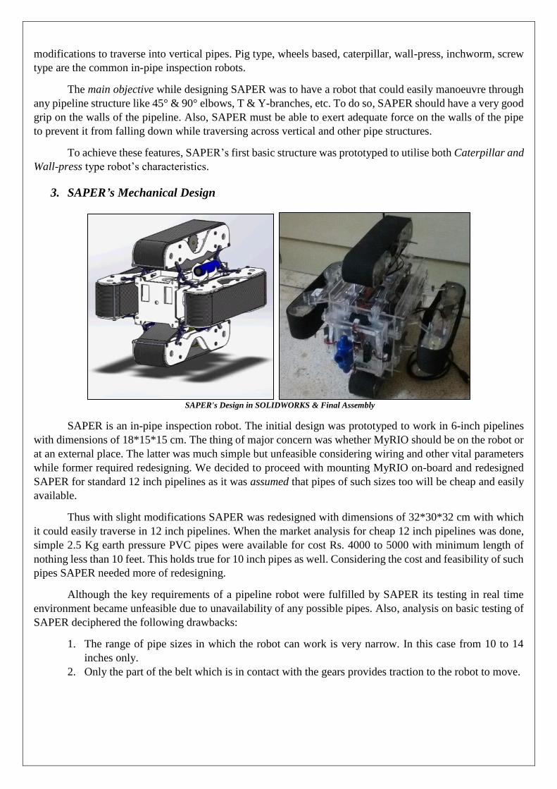
2. A lead screw assembly is deployed to adjust SAPER’s dimensions with which it can easily traverse
in pipes of sizes varying from 6 inches to 14 inches thereby increasing its application areas.
Lead Screw mechanism implementation via a 15mm diameter nut bolts.
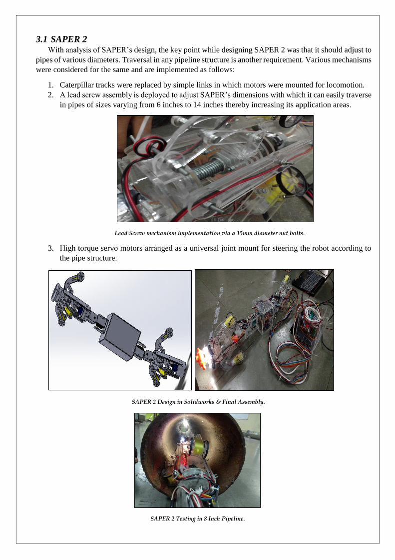
3. High torque servo motors arranged as a universal joint mount for steering the robot according to
the pipe structure.
SAPER 2 Design in Solidworks & Final Assembly.
SAPER 2 Testing in 8 Inch Pipeline.
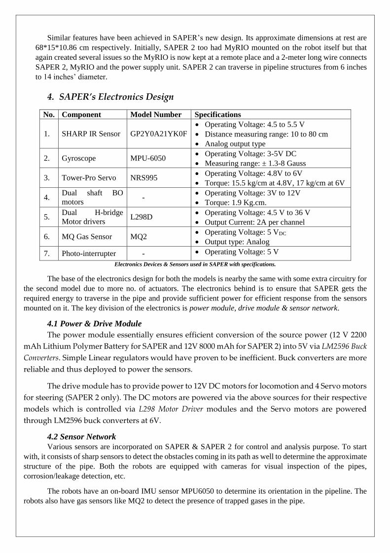
Similar features have been achieved in SAPER’s new design. Its approximate dimensions at rest are
68*15*10.86 cm respectively. Initially, SAPER 2 too had MyRIO mounted on the robot itself but that
again created several issues so the MyRIO is now kept at a remote place and a 2-meter long wire connects
SAPER 2, MyRIO and the power supply unit. SAPER 2 can traverse in pipeline structures from 6 inches
to 14 inches’ diameter.
4. SAPER’s Electronics Design
No. Component Model Number Specifications
1. SHARP IR Sensor GP2Y0A21YK0F
Operating Voltage: 4.5 to 5.5 V
Distance measuring range: 10 to 80 cm
Analog output type
2. Gyroscope MPU-6050 Operating Voltage: 3-5V DC
Measuring range: ± 1.3-8 Gauss
3. Tower-Pro Servo NRS995 Operating Voltage: 4.8V to 6V
Torque: 15.5 kg/cm at 4.8V, 17 kg/cm at 6V
4. Dual shaft BO
motors -
Operating Voltage: 3V to 12V
Torque: 1.9 Kg.cm.
5. Dual H-bridge
Motor drivers L298D
Operating Voltage: 4.5 V to 36 V
Output Current: 2A per channel
6. MQ Gas Sensor MQ2 Operating Voltage: 5 VDC
Output type: Analog
7. Photo-interrupter - Operating Voltage: 5 V
Electronics Devices & Sensors used in SAPER with specifications.
The base of the electronics design for both the models is nearby the same with some extra circuitry for
the second model due to more no. of actuators. The electronics behind is to ensure that SAPER gets the
required energy to traverse in the pipe and provide sufficient power for efficient response from the sensors
mounted on it. The key division of the electronics is power module, drive module & sensor network.
4.1 Power & Drive Module
The power module essentially ensures efficient conversion of the source power (12 V 2200
mAh Lithium Polymer Battery for SAPER and 12V 8000 mAh for SAPER 2) into 5V via LM2596 Buck
Converters. Simple Linear regulators would have proven to be inefficient. Buck converters are more
reliable and thus deployed to power the sensors.
The drive module has to provide power to 12V DC motors for locomotion and 4 Servo motors
for steering (SAPER 2 only). The DC motors are powered via the above sources for their respective
models which is controlled via L298 Motor Driver modules and the Servo motors are powered
through LM2596 buck converters at 6V.
4.2 Sensor Network
Various sensors are incorporated on SAPER & SAPER 2 for control and analysis purpose. To start
with, it consists of sharp sensors to detect the obstacles coming in its path as well to determine the approximate
structure of the pipe. Both the robots are equipped with cameras for visual inspection of the pipes,
corrosion/leakage detection, etc.
The robots have an on-board IMU sensor MPU6050 to determine its orientation in the pipeline. The
robots also have gas sensors like MQ2 to detect the presence of trapped gases in the pipe.
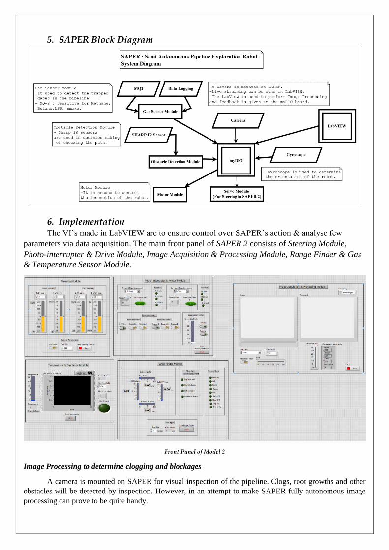
5. SAPER Block Diagram
6. Implementation The VI’s made in LabVIEW are to ensure control over SAPER’s action & analyse few
parameters via data acquisition. The main front panel of SAPER 2 consists of Steering Module,
Photo-interrupter & Drive Module, Image Acquisition & Processing Module, Range Finder & Gas
& Temperature Sensor Module.
Front Panel of Model 2
Image Processing to determine clogging and blockages
A camera is mounted on SAPER for visual inspection of the pipeline. Clogs, root growths and other
obstacles will be detected by inspection. However, in an attempt to make SAPER fully autonomous image
processing can prove to be quite handy.

This can be done by acquiring the images of the pipeline, extracting appropriate colour planes, filtering
it and then thresholding the image such that the back ground pipe is removed from it. The remaining part of
the image is thus the clogs and obstacles.
Pipe Thresholding Script Setup
Pipe Images before Thresholding (Left) and after Thresholding (Right).
The contour of the clogs can be measured and if it is greater than the acceptable size, a complete
blockage exists in the pipe. The algorithm for this is in its development.
Determining the Orientation of Robot in the Pipe
There are chances that the initial orientation of SAPER at which it was released in the pipe will vary
as the robot moves through various pipe structures. SAPER will be equipped with an IMU MPU-6050 sensor
to determine its orientation in the pipe.
Front View of SAPER with different orientation in the pipe.
With the help of LabVIEW’s 3D Picture Control sub-palette in Graphics and Sound Palette, a VI
has been designed for demonstration in which by getting the yaw, pitch and roll values from IMU the robot’s
orientation can be determined.

Orientation VI Front Panel
7. Scope and Benefits Reduces Excavation and Costly Leak Repairs
If any damage is caused in the pipeline, excavation process is carried out and replacement is done. If
inspection robots are deployed the upcoming damages can be prevented.
Real-time Inspection Data and Documentation
Detailed field reports and inspection video can be generated easily using the sensors placed on SAPER and
data logging.
8. Conclusion With SAPER we aimed to improve the existing conditions of our pipelines. With in-pipe inspection
capabilities, SAPER is designed to efficiently manoeuvre in any pipeline structure. With real time inspection
data, the pipeline health can be determined. Though our municipal corporations do have advanced
technologies for pipeline inspections, the vast network of pipelines do ensure that inspection is never
accomplished frequently. With SAPER, human efforts for inspection are reduced and a swarm of such robots
will ensure a complete log of pipeline health of a given area, analysis of which will prevent future damages.
SAPER was covered by the Times of India, Lokmat and Prabhar newspapers from 25th September to
27th September, 2016. Considering our progress, a talk with the Brihan-Mumbai Municipal Corporation has
been initiated. The authorities have shown interest in SAPER’s design and have agreed to provide us with the
necessary facilities for its future development.
With this we not only introduce technology to the pipeline networks but are also able to bring
significant impact to human life. If the health of a pipeline is known in advance, necessary measures can be
taken. This will not only prevent accidents but also reduce the costs that incur due to it.