nibe™ smo 20 · pdf file©nibe 2013. note smo 20 must be installed via an isolator...
TRANSCRIPT

User manual
LEK
NIBE™ SMO 20Control module
UHB GB 1345-2231759

A detailed explanation of the button functions can be found on page9.
How to scroll through menus and make different settings is describedon page 12.
The mode for setting the indoor temperature is reached, when in thestart mode in the main menu, by pressing the OK button twice. Readmore about the settings on page 19.
To temporarily increase the amount of hot water (if a hot water heateris installed to your SMO 20), first turn the control knob to mark menu2 (water droplet) and thenpress theOKbutton twice. Readmoreaboutthe settings on page 30.
In event of disturbances in comfortIf a disturbance in comfort of any type occurs there are somemeasuresthat can be taken before you need to contact your installer. See page50 for instructions.

Table of Contents1 Important information 2
Installation data 2
Safety information 3
Serial number 5
Contact information 6
SMO 20 – An excellent choice 8
2 The control module – the heart of the house 9Control module's function 9
Contact with SMO 20 9
Maintenance of SMO 20 17
3 SMO 20 – at your service 19Set the indoor climate 19
Set the hot water capacity 30
Get information 34
Adjust the heat pump 37
4 Disturbances in comfort 49Manage alarm 49
Troubleshooting 50
Additional heating only 52
5 Technical data 536 Glossary 54
Item register 58
1NIBE™ SMO 20Table of Contents |

1 Important information
Installation dataSMO 20Product
Serial number
Installation date
Installer
Type of docking
Accumulator/hot water heater
Heat pump/output size
Add. heat type/power
SetDe-faultset-tings
NameNo.
0/9heating curve (offset/curve slope)1.9.1
Serial number must always be given
Certification that the installation is carried out according to instructionsin NIBE's installer manual and applicable regulations.
_________________________Signed__________________Date
NIBE™ SMO 20Chapter 1 | Important information2

Safety information
This appliance can be used by children aged from 8years and above and persons with reduced physical,sensory or mental capabilities or lack of experienceand knowledge if they have been given supervision orinstruction concerning use of the appliance in a safeway and understand the hazards involved. Childrenshall not play with the appliance. Cleaning and usermaintenance shall not be made by children withoutsupervision.Rights to make any design or technical modificationsare reserved.©NIBE 2013.NOTE
SMO 20 must be installed via an isolator switch witha minimum breaking gap of 3 mm.
NOTE
If the supply cable is damaged, only NIBE, its servicerepresentative or similar authorised person may re-place it to prevent any danger and damage.
Symbols
NOTE
This symbol indicates danger to machine or person.
Caution
This symbol indicates important information about what you should ob-serve when maintaining your installation.
TIP
This symbol indicates tips on how to facilitate using the product.
3NIBE™ SMO 20Chapter 1 | Important information

MarkingSMO 20 is CE marked and fulfils IP21.
The CEmarkingmeans that NIBE ensures that the product meets all regu-lations that are placed on it based on relevant EU directives. The CE markis obligatory for most products sold in the EU, regardless where they aremade.
IP21 means that the product can be touched by hand, that objects with adiameter larger thanor equivalent to12.5mmcannotpenetrate and causedamage and that the product is protected against vertically falling drops.
NIBE™ SMO 20Chapter 1 | Important information4

Serial numberThe serial number can be found on the upper side of the cover on thecontrol module.
LEK
Caution
Always give the product's serial number when reporting a fault.
5NIBE™ SMO 20Chapter 1 | Important information

Contact informationKNV Energietechnik GmbH, Gahberggasse 11, 4861 SchörflingAT
Tel: +43 (0)7662 8963-0 Fax: +43 (0)7662 8963-44 E-mail: [email protected] Wärmetechnik AG, Winterthurerstrasse 710, CH-8247 FlurlingenCH
Tel: (52) 647 0030 Fax: (52) 647 0031 E-mail: [email protected] zavody Drazice s.r.o, Drazice 69, CZ - 294 71 Benatky nadJizerou
CZ
Tel: +420 326 373 801 Fax: +420 326 373 803 E-mail: [email protected] Systemtechnik GmbH, Am Reiherpfahl 3, 29223 CelleDE
Tel: 05141/7546-0 Fax: 05141/7546-99 E-mail: [email protected]ølund Varmeteknik A/S, Member of the Nibe Group, Brogårdsvej 7,6920 Videbæk
DK
Tel: 97 17 20 33 Fax: 97 17 29 33 E-mail: [email protected] www.volun-dvt.dkNIBE Energy Systems OY, Juurakkotie 3, 01510 VantaaFI
Puh: 09-274 697 0 Fax: 09-274 697 40 E-mail: [email protected] www.nibe.fiAIT France, 10 rue des Moines, 67000 HaguenauFR
Tel : 03 88062410 Fax : 03 88069015 E-mail: [email protected] Energy Systems Ltd, 3C Broom Business Park, Bridge Way,Chesterfield S41 9QG
GB
Tel: 0845 095 1200 Fax: 0845 095 1201 E-mail: [email protected] Energietechniek B.V., Postbus 634, NL 4900 AP OosterhoutNL
Tel: 0168477722Fax: 0168476998E-mail: [email protected], Brobekkveien80, 0582Oslo, Postadresse: Postboks 64Vollebekk,0516 Oslo
NO
Tel. sentralbord: +4723170520E-mail: [email protected] Sp. z o. o. Aleja Jana Pawła II 57, 15-703 BIAŁYSTOKPL
Tel: 085 662 84 90 Fax: 085 662 84 14 E-mail: [email protected]© "EVAN" 17, per. Boynovskiy, Nizhny NovgorodRU
Tel./fax +7 831 419 57 06 E-mail: [email protected] www.nibe-evan.ru
NIBE™ SMO 20Chapter 1 | Important information6

NIBE AB Sweden, Box 14, Hannabadsvägen 5, SE-285 21 MarkarydSE
Tel: +46-(0)433-73 000 Fax: +46-(0)433-73 190 E-mail: [email protected]
For countries notmention in this list, please contact Nibe Swedenor checkwww.nibe.eufor more information.
7NIBE™ SMO 20Chapter 1 | Important information

SMO 20 – An excellent choiceSMO20 is an electric controlmodule,which has been introduced to supplyyour home with inexpensive and environmentally friendly heating. Heatproduction is reliable and economical with a NIBE air/water heat pumpand accumulator/water heater.
An additional heater (for example electric/oil/gas boiler) can engageautomatically if something unexpected should occur or as reserve opera-tion.
Excellent properties for SMO 20:Easy to read display
The controlmodule has aneasy to readdisplaywith easy-to-understandmenus that facilitate setting a comfortable indoor climate.Easy to install
SMO20 is easy to install togetherwith a compatibleNIBE air/water heatpump. When installing together with these, the control module is con-nected to the heat pump, which enables you to see any heat pumpalarms in SMO 20. The size of the control module means that it can beinstalled on walls indoors for easy access to control your installation.
NIBE™ SMO 20Chapter 1 | Important information8

2 The control module – theheart of the house
Control module's functionSMO 20 is a simple electrical control module, which, together with NIBEair/water heat pump, accumulator/water heater and additional heater(e.g. electric/gas boiler), creates a complete installation. Among otherthings, it controls the heat pump, circulation pumps, reversing valves andadditional heat to supply yourhomewith inexpensive andenvironmentallyfriendly heating in the most efficient way.
Contact with SMO 20Display unit
There is a display unit on the front of the control module, which is usedto communicate with SMO 20. Here you:switch on, switch off or set the installation to emergency mode.set the indoor climate and hot water as well as adjust the installation toyour needs.receive information about settings, status and events.
9NIBE™ SMO 20Chapter 2 | The control module – the heart of the house

see different types of alarms and receive instructions about how theyare to be rectified.
Display
Instructions, settings and operational information are shown onthe display. The easy-to-read display and menu system, facilitatesnavigation between the different menus and options to set thecomfort or obtain the information you require.
A
Status lamp
The status lamp indicates the status of the control module. It:lights green during normal operation.lights yellow in emergency mode.lights red in the event of a deployed alarm.
B
OK button
The OK button is used to:confirm selections of sub menus/options/set values/page inthe start guide.
C
Back button
The back button is used to:go back to the previous menu.change a setting that has not been confirmed.
D
Control knob
The control knob can be turned to the right or left. You can:scroll in menus and between options.increase and decrease the values.change page in multiple page instructions (for example helptext and service info).
E
Switch
The switch assumes three positions:On ()
Standby ( )
Emergency mode ( )
Emergency mode must only be used in the event of a fault on thecontrol module. In this mode, the compressor in the heat pumpswitches off and the immersionheater engages. The controlmoduledisplay is not illuminated and the status lamp illuminates yellow.
F
NIBE™ SMO 20Chapter 2 | The control module – the heart of the house10

Menu system
INDOOR CLIMATE
Setting the indoor climate. See page 19.Menu 1
HOT WATER
Setting the hot water production. See page 30.Menu 2
This menu only appears if a water heater is installed in the system.
INFO
Display of temperature and other operating information and access tothe alarm log. See page 34.
Menu 3
MY SYSTEM
Setting time, date, language, display, operating mode etc. See page 37.Menu 4
11NIBE™ SMO 20Chapter 2 | The control module – the heart of the house

Operation
Tomove the cursor, turn the control knob to the left or the right.The marked position is brighter and/or has a light frame.
Selecting menu
To advance in themenu system select a mainmenu bymarkingit and then pressing the OK button. A new window then opens with submenus.
Select oneof the submenusbymarking it and thenpressing theOKbutton.
NIBE™ SMO 20Chapter 2 | The control module – the heart of the house12

Selecting options
In anoptionsmenu the current selectedoption is indicatedby agreentick.
To select another option:1. Mark the applicable option. One of the options is pre-selected
(white).2. Press the OK button to confirm the selected option. The selected
option has a green tick.
13NIBE™ SMO 20Chapter 2 | The control module – the heart of the house

Setting a value
To set a value:1. Mark the value you want to set using the control knob.2. Press the OK button. The background of the value becomes
green, which means that you have accessed the setting mode.3. Turn the control knob to the right to increase the value and to
the left to reduce the value.4. Press theOKbutton to confirm the value youhave set. To change
and return to the original value, press the Back button.
NIBE™ SMO 20Chapter 2 | The control module – the heart of the house14

Use the virtual keyboard
In some menus where text may require entering, a virtual keyboard isavailable.
Depending on the menu, you can gain access to different character setswhich you can select using the control knob. To change character table,press the Back button. If a menu only has one character set the keyboardis displayed directly.
When you have finished writing, mark "OK" and press the OK button.
15NIBE™ SMO 20Chapter 2 | The control module – the heart of the house

Scroll through the windows
Amenu can consist of several windows. Turn the control knob to scrollbetween the windows.
Scroll through the windows in the start guide
1. Turn the control knob until one of the arrows in the top left corner (atthe page number) has been marked.
2. Press the OK button to skip between the steps in the start guide.
Help menu
In many menus there is a symbol that indicates that extra help isavailable.
To access the help text:1. Use the control knob to select the help symbol.2. Press the OK button.
Thehelp text often consists of severalwindows that you can scroll betweenusing the control knob.
NIBE™ SMO 20Chapter 2 | The control module – the heart of the house16

Maintenance of SMO 20Regular checksYour heat pump requires minimal maintenance after commissioning. Onthe other hand, it is recommended that you check your installation regu-larly. For more information regarding the maintenance of heat pumpsand/or accumulator tanks/water heaters, refer to the relevant manual.
If something unusual occurs, messages about the malfunction appear inthe display in the form of different alarm texts. See alarm managementon page 49.
Saving tipsYour heat pump installation produces heat and hot water. This occurs viathe control settings you made.
Factors that affect the energy consumption are, for example, indoor tem-perature, hot water consumption, the insulation level of the house andwhether the house has many large window surfaces. The position of thehouse, e.g. wind exposure is also an affecting factor.
If you activate "Hot water Economy", less energy is used.
Power consumption
Increasing the indoor temperatureonedegree increases power consump-tion by approx. 5%.
Domestic electricity
In the past it has been calculated that an average Swedish household hasan approximate annual consumption of 5000 kWh domestic electri-city/year. In today's society it is usually between 6000-12.000 kWh/year.
Approx-imateannualcon-sump-tion
(kWh)
Normal Output(W)
Equipment
StandbyOperation3802200Flat-screen (Operation: 5 h/day, Standby: 19
h/day)901011Digital box (Operation: 5 h/day, Standby: 19
h/day)45515DVD (Operation: 2 h/week)
17NIBE™ SMO 20Chapter 2 | The control module – the heart of the house

Approx-imateannualcon-sump-tion
(kWh)
Normal Output(W)
Equipment
672160TV games console (Operation: 6 h/week)50140Radio/stereo (Operation: 3 h/day)1202100Computer incl. screen (Operation: 3 h/day,
standby 21 h/day)175-60Bulb (Operation 8 h/day)55-20Spot light, Halogen (Operation 8 h/day)165-100Cooler (Operation: 24 h/day)380-120Freezer (Operation: 24 h/day)365-1500Oven, hob (Operation: 40 min/day)310-3000Oven (Operation: 2 h/week)730-2000Dishwasher, cold water connection (Opera-
tion 1 time/day)730-2000Washing machine (Operation: 1 time/day)730-2000Tumble drier (Operation: 1 time/day)100-1000Vacuum cleaner (Operation: 2 h/week)50-400Engine block heater (Operation: 1 h/day, 4
months a year)100-800Passenger compartment heater (Operation:
1 h/day, 4 months a year)
These values are approximate example values.
Example: A family with 2 children live in a house with 1 flat-screen TV, 1digital box, 1 DVD player, 1 TV games console, 2 computers, 3 stereos, 2bulbs in the WC, 2 bulbs in the bathroom, 4 bulbs in the kitchen, 3 bulbsoutside, a washing machine, tumble drier, fridge, freezer, oven, vacuumcleaner, engine block heater = 6240 kWh domestic electricity/year.
Energy meter
Check the accommodation's energy meter regularly, preferably once amonth. This will indicate any changes in power consumption.
NIBE™ SMO 20Chapter 2 | The control module – the heart of the house18

3 SMO 20 – at your service
Set the indoor climateOverview
Sub-menus
For the menu INDOOR CLIMATEthere are several sub-menus. Statusinformation for the relevantmenucanbe found on the display to the rightof the menus.
temperature Setting the temperaturefor the climate system. The status in-formation shows the set values for theclimate system.
scheduling Scheduling heating.Status information "set" is displayedif you set a schedule but it is not active at the moment, "holiday setting"is displayed if the vacation schedule is active at the same time as theschedule (the vacation function is prioritised), "active" displays if any partof the schedule is active, otherwise it displays "off".
advanced Settingofheat curve, adjustingwithexternal contact,minimumvalue for supply temperature, own curve and point offset.
temperatureIf the house has several climate sys-tems, this is indicated on the displayby a thermometer for each system.
Set the temperature (with roomsensors installed and activated):
Setting range: 5 - 30 °C
Default value: 20
The value in the display appears as atemperature in °C if the heating system is controlled by a room sensor.
Menu1.1
To change the room temperature, use the control knob to set the desiredtemperature in the display. Confirm the new setting by pressing the OKbutton. The new temperature is shown on the right-hand side of thesymbol in the display.
19NIBE™ SMO 20Chapter 3 | SMO 20 – at your service

Setting the temperature (without room sensors activated):
Setting range: -10 to +10
Default value: 0
The display shows the set values for heating (curve offset). To increase orreduce the indoor temperature, increaseor reduce the valueon thedisplay.
Use the control knob to set a new value. Confirm the new setting bypressing the OK button.
The number of steps the value has to be changed to achieve a degreechange of the indoor temperature depends on the heating installation.One step is usually enoughbut in somecases several stepsmaybe required.
Setting the desired value. The new value is shown on the right-hand sideof the symbol in the display.
Caution
An increase in the room temperature can be slowed by the thermostatsfor the radiators or under floor heating. Therefore, open the thermostatsfully, except in those rooms where a cooler temperature is required, e.g.bedrooms.
TIP
Wait 24hours beforemaking anew setting, so that the room temperaturehas time to stabilise.
If it is cold outdoors and the room temperature is too low, increase thecurve slope in menu 1.9.1 by one increment.
If it is cold outdoors and the room temperature is too high, lower thecurve slope menu 1.9.1 by one increment.
If it is warm outdoors and the room temperature is too low, increase thevalue in menu 1.1 by one increment.
If it is warm outdoors and the room temperature is too high, reduce thevalue in menu 1.1 by one increment.
NIBE™ SMO 20Chapter 3 | SMO 20 – at your service20

schedulingscheduling1.3
heating off
In the menu scheduling indoor cli-mate (heating) is scheduled for eachweekday.
You can also schedule a longer periodduring a selected period (vacation) inmenu 4.7.
Menu1.3
heatingIncreases or decreases in the accommodation temperature can be sched-uled here for up to three time periods per day. If a room sensor is installed
Menu1.3.1
and activated the desired room temperature (°C) is set during the timeperiod. Without an activated room sensor the desired change is set (ofsetting in menu 1.1). One step is usually enough to change the roomtemperature by one degree, but in some cases several steps may be re-quired.
Schedule: The schedule to be changed is selected here.
Activated: Scheduling for the selected period is activated here. Set timesare not affected at deactivation.
Day: Selectwhich day or days of theweek the schedule is to apply to here.To remove the scheduling for a particular day, the time for that day mustbe reset by setting the start time to the same as the stop time. If the line"all" is used, all days in the period are set for these times.
21NIBE™ SMO 20Chapter 3 | SMO 20 – at your service
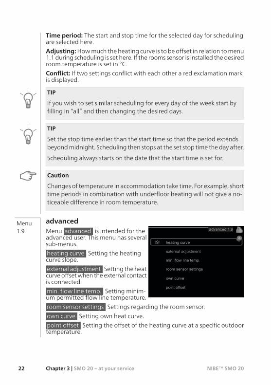
Time period: The start and stop time for the selected day for schedulingare selected here.
Adjusting:Howmuch theheating curve is to beoffset in relation tomenu1.1 during scheduling is set here. If the rooms sensor is installed thedesiredroom temperature is set in °C.
Conflict: If two settings conflict with each other a red exclamation markis displayed.
TIP
If you wish to set similar scheduling for every day of the week start byfilling in “all” and then changing the desired days.
TIP
Set the stop time earlier than the start time so that the period extendsbeyondmidnight. Scheduling then stops at the set stop time theday after.
Scheduling always starts on the date that the start time is set for.
Caution
Changesof temperature in accommodation take time. For example, shorttime periods in combination with underfloor heating will not give a no-ticeable difference in room temperature.
advancedMenu advanced is intended for theadvanced user. This menu has severalsub-menus.
heating curve Setting the heatingcurve slope.
external adjustment Setting theheatcurveoffsetwhen theexternal contactis connected.
min. flow line temp. Setting minim-um permitted flow line temperature.
Menu1.9
room sensor settings Settings regarding the room sensor.
own curve Setting own heat curve.
point offset Setting the offset of the heating curve at a specific outdoortemperature.
NIBE™ SMO 20Chapter 3 | SMO 20 – at your service22

heating curve
heating curve
Setting range: 0 - 15
Default value: 9
Menu1.9.1
In themenu heating curve the presecribed heating curve for your housecan be viewed. The task of the heating curve is to give an even indoortemperature, regardless of the outdoor temperature, and thereby energyefficient operation. It is from this heating curve that the control module’scontrol computer determines the temperatureof thewater to theheatingsystem, supply temperature, and therefore the indoor temperature. Youcan select heating curve and readoff how the supply temperature changesat different outdoor temperatures here.
Curve coefficient
The slopeof theheating curve indic-ates howmany degrees the supplytemperature is to be increased/re-ducedwhen theoutdoor temperat-uredrops/increases. A steeper slopemeans ahigher supply temperatureat a certain outdoor temperature.
30
40
50
60
70°C
- 40°CUTETEMPERATUR
- 10010 - 20 - 30
Brantare kurvlutning
The optimum slope depends on the climate conditions in your location, ifthe house has radiators or under floor heating and howwell insulated thehouse is.
The heating curve is setwhen the heating installation is installed, butmayneed adjusting later. Thereafter the heating curve should not need furtheradjustment.
23NIBE™ SMO 20Chapter 3 | SMO 20 – at your service

Caution
In the event of making fine adjustments for the indoor temperature, theheat curve must be offset up or down instead, this is done in menu 1.1temperature .
Curve offset
An offset of the heating curvemeans that the supply temperaturechanges asmuch for all theoutdoortemperatures, e.g. that a curve off-set of +2 steps increases the supplytemperature by 5 °C at all outdoortemperatures.
30
40
50
60
70°C
- 40°CUTETEMPERATUR
- 10010 - 20 - 30
Förskjuten värmekurva
Flow line temperature–maxim-um and minimum values
Because the flow line temperaturecannot be calculated higher thanthe set maximum value or lowerthan the set minimum value theheating curve flattens out at thesetemperatures.
30
40
50
60
70°C
- 40°CUTETEMPERATUR
- 10010 - 20 - 30
Maximivärde
Minimivärde
Caution
Underfloor heating systems are normally max flow line temperature setbetween 35 and 45 °C.
Check themax temperature for your floorwith your installer/floor supplier.
The figure at the end of the curve indicates the curve slope. The figurebeside the thermometer gives the curve offset. Use the control knob toset a new value. Confirm the new setting by pressing the OK button.
Curve 0 is an own heating curve created in menu 1.9.7.
NIBE™ SMO 20Chapter 3 | SMO 20 – at your service24

To select another heat curve (slope):1. Press the OK button to access the setting mode2. Select a new heating curve. The heat curves are numbered from 0 to
15, the greater the number, the steeper the slope and the greater thesupply temperature. Heating curve 0 means that own curve (menu1.9.7) is used.
3. Press the OK button to exit the setting.
To read off a heating curve:1. Turn the control knob so that the ring on the shaft with the outdoor
temperature is marked.2. Press the OK button.3. Follow the grey line up to the heat curve and out to the left to read
off the value for the supply temperature at the selected outdoortemperature.
4. You can now select to take read outs for different outdoor temperat-ures by turning the control knob to the right or left and read off thecorresponding flow temperature.
5. Press the OK or Back button to exit read off mode.
TIP
Wait 24hours beforemaking anew setting, so that the room temperaturehas time to stabilise.
If it is cold outdoors and the room temperature is too low, increase thecurve slope by one increment.
If it is cold outdoors and the room temperature is too high, lower thecurve slope by one increment.
If it is warm outdoors and the room temperature is too low, increase thecurve offset by one increment.
If it is warm outdoors and the room temperature is too high, lower thecurve offset by one increment.
25NIBE™ SMO 20Chapter 3 | SMO 20 – at your service

external adjustment
climate system
Setting range: -10 to+10ordesiredroom temperature if the roomsensor is installed.
Default value: 0
Menu1.9.2
Connecting an external contact, for example, a room thermostat or a timerallows you to temporarily or periodically raise or lower the room temper-ature. When the contact is on, the heat curve offset is changed by thenumber of steps selected in the menu. If a room sensor is installed andactivated the desired room temperature (°C) is set.
min. flow line temp.
climate system
Setting range: 5-70 °C
Default value: 20 °C
Menu1.9.3
Set the minimum temperature on the supply temperature to the climatesystem. This means that SMO 20 never calculates a temperature lowerthan that set here.
TIP
The value can be increased if you have, for example, a cellar that you al-ways want to heat, even in summer.
You may also need to increase the value in "stop heating" menu 4.9.2"auto mode setting".
NIBE™ SMO 20Chapter 3 | SMO 20 – at your service26

room sensor settings
factor system
Setting range: 0.0 - 6.0
Default value: 2.0
Menu1.9.4
Room sensors to control the room temperature can be activated here.
Here you can set a factor (a numerical value) that determines howmuchan over or sub normal temperature (the difference between the desiredand actual room temperature) in the room is to affect the supply temper-ature to the climate system. A higher value gives a greater and fasterchange of the heating curve's set offset.
NOTE
Too high a set value for "factor system" can (depending on your climatesystem) produce an unstable room temperature.
27NIBE™ SMO 20Chapter 3 | SMO 20 – at your service

own curve
supply temperature
Setting range: 0 – 80 °C
You can create your own heating curve here, if there are special require-ments, by setting the desired supply temperatures for different outdoortemperatures.
Caution
Curve 0 in menu 1.9.1 must be selected for this curve to apply.
Menu1.9.7
point offset
outdoor temp. point
Setting range: -40 – 30 °C
Default value: 0 °C
change in curve
Setting range: -10 – 10 °C
Default value: 0 °C
Menu1.9.8
Select a change in the heating curve at a certain outdoor temperaturehere. One step is usually enough to change the room temperature by onedegree, but in some cases several steps may be required.
The heat curve is affected at ± 5 °C from set outdoor temp. point.
It is important that the correct heating curve is selected so that the roomtemperature is experienced as even.
NIBE™ SMO 20Chapter 3 | SMO 20 – at your service28

TIP
If it is cold in the house, at, for example -2 °C, "outdoor temp. point" is setto "-2" and "change in curve" is increased until the desired room temper-ature is maintained.
Caution
Wait 24hours beforemaking anew setting, so that the room temperaturehas time to stabilise.
29NIBE™ SMO 20Chapter 3 | SMO 20 – at your service

Set the hot water capacityOverview
Sub-menus
This menu only appears if a waterheater is docked to the heat pump.
For the menu HOTWATER there areseveral sub-menus. Status informationfor the relevant menu can be foundon the display to the right of themenus.
temporary lux Activation of tempor-ary increase in the hot water temper-ature. Status information displays“off" or what length of time of thetemporary temperature increase remains.
comfortmode Settinghotwater comfort. The status informationdisplayswhat mode is selected, "economy", "normal" or "luxury".
scheduling Scheduling hot water comfort. The status information "set"appears if you have set scheduling but it is not currently active, "holidaysetting" appears if holiday setting is active at the same time as scheduling(when the holiday function is prioritised), "active" appears if any part ofscheduling is active, otherwise "off" appears.
advanced Setting periodic increase in the hot water temperature.
temporary lux
Setting range: 3, 6 and 12 hoursand mode "off"
Default value: "off"
Menu2.1
When hotwater requirement has temporarily increased thismenu can beused to select an increase in the hot water temperature to lux mode fora selectable time.
NIBE™ SMO 20Chapter 3 | SMO 20 – at your service30

Caution
If comfort mode "luxury" is selected in menu 2.2 no further increase canbe carried out.
The function is activated immediately when a time period is selected andconfirmedusing theOKbutton. The remaining time for the selected settingis shown to the right.
When the time has run out SMO 20 returns to the mode set in menu 2.2.
Select “off" to switch off temporary lux .
comfort mode
Setting range: economy, normal,luxury
Default value: normal
Menu2.2
The difference between the selectable modes is the temperature of thehot tap water. Higher temperaturemeans that the hot water lasts longer.
economy: This mode gives less hot water than the other, but is moreeconomical. Thismode canbeused in smaller householdswith a small hotwater requirement.
normal: Normal mode gives a larger amount of hot water and is suitablefor most households.
luxury: Luxmode gives the greatest possible amount of hot water. In thismode, the immersion heater, as well as the compressor, is used to heathot water, which may increase operating costs.
schedulingTwodifferent periods of hotwater comfort per day canbe scheduledhere.
Menu2.3
Scheduling is activated/deactivated by ticking/unticking"activated". Settimes are not affected at deactivation.
31NIBE™ SMO 20Chapter 3 | SMO 20 – at your service

all
mon
tues
we
thur
fri
sat
sun
activated
schedule 2schedule 1
SCHEDULING HOTWATER 2.3
normal
Time period AdjustingDay
Activated Schedule
Conflict
Schedule: The schedule to be changed is selected here.
Activated: Scheduling for the selected period is activated here. Set timesare not affected at deactivation.
Day: Selectwhich day or days of theweek the schedule is to apply to here.To remove the scheduling for a particular day, the time for that day mustbe reset by setting the start time to the same as the stop time. If the line"all" is used, all days in the period are set for these times.
Time period: The start and stop time for the selected day for schedulingare selected here.
Adjusting: Set the hot water comfort that is to apply during schedulinghere.
Conflict: If two settings conflict with each other a red exclamation markis displayed.
TIP
If you wish to set similar scheduling for every day of the week start byfilling in “all” and then changing the desired days.
TIP
Set the stop time earlier than the start time so that the period extendsbeyondmidnight. Scheduling then stops at the set stop time theday after.
Scheduling always starts on the date that the start time is set for.
NIBE™ SMO 20Chapter 3 | SMO 20 – at your service32

advancedMenu advanced is intended for theadvanced user. This menu has severalsub-menus.
Menu2.9
periodic increases
period
Setting range: 1 - 90 days
Default value: 14 days
start time
Setting range: 00:00 - 23:00
Default value: 00:00
Menu2.9.1
To prevent bacterial growth in the water heater, the heat pump and anyadditional heat can increase the hot water temperature for a short timeat regular intervals.
The length of time between increases can be selected here. The time canbe set between1 and90days. Factory setting is 14 days. Untick "activated"to switch off the function.
33NIBE™ SMO 20Chapter 3 | SMO 20 – at your service

Get informationOverview
Sub-menus
For the menu INFO there are severalsub-menus. No settings can be madein these menus, they just display in-formation. Status information for therelevant menu can be found on thedisplay to the right of the menus.
service info shows temperature levelsand settings in the installation.
compressor info shows operatingtimes, number of starts etc for thecompressor in the heat pump.
add. heat info displays information about the additional heat's operatingtimes etc.
alarm log shows the latest alarms.
indoor temp. log the average temperature indoorsweek byweek duringthe past year.
service infoInformation about the actual operat-ing status of the installation (e.g. cur-rent temperatures etc.) can be ob-tainedhere.No changes canbemade.
The information is on several pages.Turn the control knob to scrollbetween the pages.
Symbols in this menu:
Menu3.1
HeatingCom-pressor
Hot wa-ter
Addition
NIBE™ SMO 20Chapter 3 | SMO 20 – at your service34

compressor infoInformation about the compressor’soperating status and statistics can beobtained here. No changes can bemade.
The information is on several pages.Turn the control knob to scrollbetween the pages.
Menu3.2
add. heat infoInformation about the additionalheat's settings, operating status andstatistics can be obtained here. Nochanges can be made.
The information is on several pages.Turn the control knob to scrollbetween the pages.
Menu3.3
35NIBE™ SMO 20Chapter 3 | SMO 20 – at your service

alarm logalarm log3.4To facilitate fault-finding the installa-
tion's operating status at alarm alertsis stored here. You can see informa-tion for the 10 most recent alarms.
To view the run status in the event ofan alarm, mark the alarm and pressthe OK button.
Information about an alarm.
Menu3.4
indoor temp. logHere you can see the average temper-ature indoors week by week duringthepast year. Thedotted line indicatesthe annual average temperature.
The average outdoor temperature isonly shown if a room temperaturesensor/room unit is installed.
To readoff an average temperature1. Turn the control knob so that the
ring on the shaft with the weeknumber is marked.
2. Press the OK button.3. Follow the grey line up to the graph and out to the left to read off the
average indoor temperature at the selected week.4. You can now select to take read outs for different weeks by turning
the control knob to the right or left and read off the average temper-ature.
5. Press the OK or Back button to exit read off mode.
Menu3.5
NIBE™ SMO 20Chapter 3 | SMO 20 – at your service36

Adjust the heat pumpOverview
Sub-menusMY SYSTEM 4
op. mode
time & date
language / language
off
auto
plus functions
holiday setting
advanced
For the menu MY SYSTEM there areseveral sub-menus. Status informationfor the relevant menu can be foundon the display to the right of themenus.
plus functions Settings applying toany installed extra functions in theheating system.
op. mode Activation of manual orautomatic operatingmode. The statusinformation shows the selected oper-ating mode.
time & date Setting current time and date.
language Select the language for thedisplay here. The status informationshows the selected language.
holiday setting Vacation scheduling heating and hot water comfort.Status information "set" is displayed if you set a vacation schedule but itis not active at themoment, "active" is displayed if any part of the vacationschedule is active, otherwise it displays " off".
advanced Settings of control module work mode.
plus functionsplus functions4.1
internet
Settings for any additional functionsinstalled in SMO 20 can be made inthe sub menus.
Menu4.1
37NIBE™ SMO 20Chapter 3 | SMO 20 – at your service

internet
nibe uplink
internet4.1.3
tcp/ip settings
proxy settings
Here youmake settings for connectingSMO 20 to the internet.
Menu4.1.3
NOTE
For these functions to work the net-work cable must be connected.
nibe uplink
request new connection string
serial number
nibe uplink 4.1.3.1
switch off all users
connection string
number of users
Here you can manage the installa-tion's connection to NIBE Uplink™(http://www.nibeuplink.com)andseethenumber of users connected to theinstallation via the internet.
A connected user has a user accountin NIBE Uplink™ which have beengiven permission to control and/ormonitor your installation.
Request new connection string
To connect a user account on NIBE Uplink™ to your installation, youmustrequest a unique connection string.
Menu4.1.3.1
1. Mark “request new connection string" and press the OK button.2. The installation now communicates with NIBE Uplink™ to create a
connection string.3. When a connection string has been received, it is shown in this menu
at "connection string" and is valid for 60 minutes.
Disconnect all users1. Mark “switch off all users" and press the OK button.2. The installationnowcommunicateswithNIBEUplink™ to release your
installation from all connected users via the internet.
NOTE
After disconnecting all users none of them can monitor or control yourinstallation viaNIBEUplink™without requesting anewconnection string.
NIBE™ SMO 20Chapter 3 | SMO 20 – at your service38

tcp/ip settingstcp/ip settings4.1.3.8
confirm reset
automatic
ip-address
net mask
gateway
dns
You can set TCP/IP settings for yourinstallation here.
Automatic setting (DHCP)
Menu4.1.3.8
1. Tick “automatic". The installationnow receives the TCP/IP settingsusing DHCP.
2. Mark “confirm" and press the OKbutton.
Manual setting1. Untick "automatic", you now have access to several setting options.2. Mark “ip-address" and press the OK button.3. Enter the correct details via the virtual keypad.4. Mark “OK" and press the OK button.5. Repeat 1 - 3 for "net mask", "gateway" and "dns".6. Mark “confirm" and press the OK button.
Caution
The installation cannot connect to the internetwithout the correct TCP/IPsettings. If unsure about applicable settings use the automatic mode orcontact your network administrator (or similar) for further information.
TIP
All settingsmade since opening themenu canbe reset bymarking "reset"and pressing the OK button.
proxy settings
confirm reset
proxy settings 4.1.3.9
use proxy
server
port
user name
password
You can set proxy settings for yourinstallation here.
Proxy settings areused togive connec-tion information to a intermediateserver (proxy server) between the in-stallation and Internet. These settingsare primarily used when the installa-tion connects to the Internet via acompany network. The installationsupports proxy authentication of theHTTP Basic and HTTP Digest type.
Menu4.1.3.9
If unsure about applicable settings use the preset settings or contact yournetwork administrator (or similar) for further information.
39NIBE™ SMO 20Chapter 3 | SMO 20 – at your service

Setting1. Tick “use proxy" if you do not want to use a proxy.2. Mark “server" and press the OK button.3. Enter the correct details via the virtual keypad.4. Mark “OK" and press the OK button.5. Repeat 1 - 3 for "port", "user name" and "password".6. Mark “confirm" and press the OK button.
TIP
All settingsmade since opening themenu canbe reset bymarking "reset"and pressing the OK button.
SG ReadyThis function can only be used inmains networks that support the "SGReady"-standard (Germany).
Make settings for the function "SGReady" here.
affect room temperature
Here you setwhether roomtemperat-ure should be affected when activat-ing "SG Ready".
With low price mode of "SG Ready" the parallel offset of the indoor tem-perature is increased by "+1". If a room sensor is installed and activated,the desired room temperature increases by 1 °C.
Menu4.1.5
With over capacity mode of "SG Ready" the parallel offset for the indoortemperature is increasedby"+2". If a room sensor is installed and activated,the desired room temperature increases by 2 °C.
affect hot water
Here you setwhether the temperature of the hotwater should be affectedwhen activating "SG Ready".
With lowpricemodeon "SGReady" the stop temperature of thehotwateris set as high as possible at only compressor operation (immersion heaternot permitted).
With over capacity mode of "SG Ready" the hot water is set to "luxury"(immersion heater permitted).
NIBE™ SMO 20Chapter 3 | SMO 20 – at your service40

NOTE
The function must be connected and activated in your SMO 20.
op. mode
op. mode
Setting range: auto, manual, add.heat only
Default value: auto
functions
Setting range: compressor, addi-tion, heating
Menu4.2
The control module operating mode is usually set to "auto". It is also pos-sible to set the control module to "add. heat only", when only additionalheat is used, or "manual" and then select what functions are to be permit-ted.
Change the operating mode by marking the desired mode and pressingthe OK button. When an operating mode is selected it shows what in thecontrol module is permitted (crossed out = not permitted) and selectablealternatives to the right. To select selectable functions that are permittedor not you mark the function using the control knob and press the OKbutton.
Operating mode auto
In this operating mode the control module automatically selects whatfunctions are permitted.
Operating mode manual
In this operating mode you can select what functions are permitted. Youcannot deselect "compressor" in manual mode.
Operating mode add. heat only
In this operating mode the compressor is not active and only additionalheating is used.
41NIBE™ SMO 20Chapter 3 | SMO 20 – at your service

Caution
If you choose mode "add. heat only" the compressor is deselected andthere is a higher operating cost.
Caution
You cannot change from only additional heat if you do not have a heatpump connected (see menu 5.2.2).
Functions
"compressor" is that which produces heating and hot water for the ac-commodation. If "compressor" is deselected, a symbol is displayed in themain menu on the symbol for the control module. You cannot deselect"compressor" in manual mode.
"addition" is what helps the compressor to heat the accommodationand/or the hot water when it cannot manage the whole requirementalone.
"heating" means that you get heat in the accommodation. You candeselect the function when you do not wish to have heating running.
time & dateSet time and date, display mode andtime zone here.
Menu4.4
TIP
Time and date are set automaticallyif the heat pump is connected toNIBEUplink™. To obtain the correct time,the time zone must be set.
languageChoose the language that you wantthe information to be displayed inhere.
Menu4.6
NIBE™ SMO 20Chapter 3 | SMO 20 – at your service42

holiday settingIf a room sensor is installed and activ-ated the desired room temperature(°C) is set during the time period. Thissetting applies to all climate systemswith room sensors.
If a room sensor is not activated, thedesired offset of the heating curve isset. This setting applies to all climatesystems without room sensors. Onestep is usually enough to change theroomtemperaturebyonedegree, butin some cases several steps may be required.
Menu4.7
Vacation scheduling starts at 00:00 on the start date and stops at 23:59on the stop date.
TIP
Complete holiday setting about a day before your return so that roomtemperature and hot water have time to regain usual levels.
TIP
Set the vacation setting in advance and activate just before departure inorder to maintain the comfort.
Caution
If you choose to switch off hot water production during the vacation“periodic increases" (preventing bacterial growth) are blocked during thistime. "periodic increases" started in conjunctionwith the vacation settingbeing completed.
advancedMenu advanced is intended for theadvanced user. This menu has severalsub-menus.
Menu4.9
43NIBE™ SMO 20Chapter 3 | SMO 20 – at your service

op. prioritisation
op. prioritisation
Setting range: 0 to 180 min
Default value: 30 min
The indicator marks where in the cycle the installation is.
If 0 minutes is selected it means that requirement is not prioritised, butwill only be activated when there is no other requirement.
Menu4.9.1
auto mode setting
stop heating
Setting range: -20 – 40 °C
Default values: 20
stop additional heat
Setting range: -25 – 40 °C
Default values: 15
filtering time
Setting range: 0 – 48 h
Default value: 24 h
Menu4.9.2
When the operating mode is set to "auto", the control module selectswhen start and stop of additional heat and heat production is permitted,dependent on the average outdoor temperature.
Select the average outdoor temperatures in this menu.
You can also set the time over which (filtering time) the average temper-ature is calculated. If you select 0, the present outdoor temperature isused.
Caution
It cannot be set "stop additional heat" higher than "stop heating".
NIBE™ SMO 20Chapter 3 | SMO 20 – at your service44

degree minute setting
current value
Setting range: -3000 – 3000
start compressor
Setting range: -1000 – -30
Default value: -60
start diff additional heat
Setting range: 100 – 1000
Default value: 400
diff. between additional steps
Setting range: 0 – 1000
Default value: 30
Menu4.9.3
Degree minutes are a measurement of the current heating requirementin the house and determine when the compressor respectively additionalheat will start/stop.
Caution
Higher value on "start compressor" gives more compressor starts, whichincreases wear in the compressor. Too low value can give uneven indoortemperatures.
factory setting userAll settings that are available to theuser (including advancedmenus) canbe reset to default values here.
Menu4.9.4
Caution
After factory setting, personal set-tings such as heating curves must bereset.
schedule blockingThe additional heat canbe scheduled to beblocked for up to twodifferenttime periods here.
Menu4.9.5
When scheduling is active the relevant blocking symbol is shown in themain menu on the symbol for the control module.
45NIBE™ SMO 20Chapter 3 | SMO 20 – at your service

Schedule: The period to be changed is selected here.
Activated: Scheduling for the selected period is activated here. Set timesare not affected at deactivation.
Day: Selectwhich day or days of theweek the schedule is to apply to here.To remove the scheduling for a particular day, the time for that day mustbe reset by setting the start time to the same as the stop time. If the line"all" is used, all days in the period are set for these times.
Time period: The start and stop time for the selected day for schedulingare selected here.
Blocking: The desired blocking is selected here.
Conflict: If two settings conflict with each other a red exclamation markis displayed.
Blocking the compressor in the outdoor unit.
Blocking additional heat.
TIP
If you wish to set similar scheduling for every day of the week start byfilling in “all” and then changing the desired days.
NIBE™ SMO 20Chapter 3 | SMO 20 – at your service46

TIP
Set the stop time earlier than the start time so that the period extendsbeyondmidnight. Scheduling then stops at the set stop time theday after.
Scheduling always starts on the date that the start time is set for.
Caution
Long term blocking can cause reduced comfort and operating economy.
schedule silent modeThe compressor can be scheduled to be set to "quiet mode" (the heatpump must support this) for up to two different time periods here.
Menu4.9.6
When scheduling is active the "quiet mode" symbol is shown in the mainmenu on the symbol for the control module.
Schedule: The period to be changed is selected here.
Activated: Scheduling for the selected period is activated here. Set timesare not affected at deactivation.
Day: Selectwhich day or days of theweek the schedule is to apply to here.To remove the scheduling for a particular day, the time for that day mustbe reset by setting the start time to the same as the stop time. If the line"all" is used, all days in the period are set for these times.
Time period: The start and stop time for the selected day for schedulingare selected here.
47NIBE™ SMO 20Chapter 3 | SMO 20 – at your service
Conflict: If two settings conflict with each other a red exclamation markis displayed.
TIP
If you wish to set similar scheduling for every day of the week start byfilling in “all” and then changing the desired days.
TIP
Set the stop time earlier than the start time so that the period extendsbeyondmidnight. Scheduling then stops at the set stop time theday after.
Scheduling always starts on the date that the start time is set for.
Caution
Long term scheduling of "quiet mode" can cause reduced comfort andoperating economy.
NIBE™ SMO 20Chapter 3 | SMO 20 – at your service48

4 Disturbances in comfort
In most cases, the control module notes a malfunction and indicates thiswith alarms and shows instructions to rectify it in the display. See "Managealarm" for information about managing alarms. If the malfunction doesnot appear in the display, or if the display is not lit, the followingtroubleshooting guide can be used.
Manage alarmIn the event of an alarm, some kind ofmalfunction has occurred, which isindicatedby the status lampchangingfrom green continuously to red con-tinuously. In addition, an alarm bellappears in the information window.
AlarmIn the event of an alarm with a redstatus lamp a malfunction has oc-curred that the heat pump and/orcontrol module cannot remedy itself.In the display, by turning the control knob and pressing the OK button,you can see the type of alarm it is and reset it. You can also choose to setthe installation to aid mode.
info / action Here you can read what the alarm means and receive tipson what you can do to correct the problem that caused the alarm.
reset alarm In most cases it is enough to select "reset alarm" to correctthe problem that caused the alarm. If a green light illuminates after select-ing "reset alarm" the alarm has been remedied. If a red light is still visibleandamenu called ”alarm” is visible in thedisplay, theproblem that causedthe alarm remains. If the alarm disappears and then returns, contact yourinstaller.
aid mode ”aid mode” is a type of emergency mode. This means that theinstallation produces heat and/or hot water despite there being somekind of problem. This can mean that the heat pump's compressor is notrunning. In this case any electrical addition produces heat and/or hotwater.
Caution
Selecting "aidmode” is not the sameas correcting theproblem that causedthe alarm. The status lamp will therefore continue to be red.
49NIBE™ SMO 20Chapter 4 | Disturbances in comfort

If the alarm does not reset, contact your installer for suitable remedial ac-tion.
NOTE
Always communicate theproduct's serial number (14digits)when report-ing a fault.
TroubleshootingIf the operational interference is not shown in the display the followingtips can be used:
Basic actionsStart by checking the following possible fault sources:The switch's position.Group and main fuses of the accommodation.The property's earth circuit breaker.
Low hot water temperature or a lack of hot waterThis part of the fault-tracing chapter only applies if the water heater is in-stalled in the system.Closed or choked filling valve for the hot water heater.Open the valve.
Mixing valve (if there is one installed) set too low.Adjust the mixer valve.
Control module in incorrect operating mode.If mode "manual" is selected, select "addition".
Large hot water consumption.Wait until the hot water has heated up. Temporarily increased hotwater capacity (temporary lux) can be activated in menu 2.1.
Too low hot water setting.Enter menu 2.2 and select a higher comfort mode.
Too low or no operating prioritisation of hot water.Enter menu 4.9.1 and increase the time for when hot water is to beprioritised.
Low room temperatureClosed thermostats in several rooms.Set the thermostats to max in as many rooms as possible. Adjust theroom temperature via menu 1.1 instead of choking the thermostats.
Control module in incorrect operating mode.
NIBE™ SMO 20Chapter 4 | Disturbances in comfort50

Enter menu 4.2. If mode "auto" is selected, select a higher value on"stop heating“ in menu 4.9.2.If mode "manual" is selected, select "heating". If this is not enough,select "addition".
Too low set value on the automatic heating control.Enter menu 1.1 "temperature" and adjust the offset of the heatingcurve. If the room temperature is only low in cold weather the curveslope in menu 1.9.1 "heating curve" needs adjusting up.
Too low or no operating prioritisation of heat.Enter menu 4.9.1 and increase the time for when heating is to be pri-oritised.
"Holiday mode" activated in menu 4.7.Enter menu 4.7 and select “Off”.
External switch for changing the room heating activated.Check any external switches.
Air in the climate system.Vent the climate system.
Closed valves to the climate system.Open the valves (contact your installer for assistance in finding them).
High room temperatureToo high set value on the automatic heating control.Enter menu 1.1 (temperature) and adjust the heat curve offsetdownwards. If the room temperature is only high in cold weather thecurve slope inmenu 1.9.1 (heating curve) needs to be adjusted down.
External switch for changing the room heating activated.Check any external switches.
Low system pressureNot enough water in the climate system.Top up the water in the climate system.
The compressor does not startThere is no heating requirement.The heat pump does not call on heating nor hot water.
Temperature conditions tripped.Wait until the temperature condition has been reset.
Minimum time between compressor starts has not been reached.Wait 30 minutes and check if the compressor has started.
Alarm tripped.Follow the display instructions.
51NIBE™ SMO 20Chapter 4 | Disturbances in comfort

Additional heating onlyIf you are unsuccessful in rectifying the fault and are unable to heat thehouse, you can, whilst waiting for assistance, continue running the heatpump in ”add. heat only”. This means that additional heating only is usedto heat the house.
Set the installation to additional heat mode1. Go to menu 4.2 op. mode.2. Mark ”add. heat only” using the control knob and then press the OK
button.3. Return to the main menus by pressing the Back button.
NOTE
If a heat pump is not connected by pipes to the system the flowmust beshut off (the pipe ends connected to each other) where the heat pumpshould have been installed.
Caution
When commissioning without NIBE air/water heat pump an alarm com-munication error may appear in the display.
The alarm is reset if the relevant heat pump is deactivated in menu 5.2.2("installed slaves").
NIBE™ SMO 20Chapter 4 | Disturbances in comfort52

5 Technical data
Detailed technical specifications for this product can be found in the in-stallation manual (www.nibe.eu).
53NIBE™ SMO 20Chapter 5 | Technical data

6 Glossary
Additional heat:The additional heat is the heat produced in addition to the heat suppliedby the compressor in your heat pump. Additional heaters can be for ex-ample, immersion heater, electric heater, solar power system,gas/oil/pellet/wood burner or district heating.
Calculated flow line temperatureThe temperature that the heat pump calculates that the heating systemrequires for an optimum accommodation temperature. The colder theoutdoor temperature, the higher the calculated supply temperature.
Circulation pumpPump that circulates liquid in a pipe system.
Climate systemClimate systems can also be called heating systems. The building is heatedusing radiators, under floor coils or convector fans.
CompressorCompresses thegas state refrigerant.When the refrigerant is compressed,the pressure and the temperature increase.
CondenserHeat exchanger where the hot gas state refrigerant condenses (cooledand becomes a liquid) and releases heat energy to the house heating andhot water systems.
COPIf it is stated that a heat pump has COP 4, this means, in principle that ifyou insert 10pence, youwill get 40penceworth of heat. It is the efficiencyof the heat pump. This is measured at differentmeasurement values, e.g.:7/45 where 7 stands for the outdoor temperature and 45 for howmanydegrees the supply temperature is.
Disturbances in comfortDisturbances in comfort are undesirable changes to the hotwater/indoorcomfort, for example when the temperature of the hot water is too lowor if the indoor temperature is not at the desired level.
A malfunction in the heat pump can sometimes be noticed in the form ofa disturbance in comfort.
NIBE™ SMO 20Chapter 6 | Glossary54

Inmost cases, theheat pumpnotes operational interference and indicatesthis with alarms and shows instructions in the display.
Domestic hot waterThe water one showers in for example.
DUT, dimensioned outdoor temperatureThe dimensioned outdoor temperature differs depending on where youlive. The lower the dimensionedoutdoor temperature, the lower the valueshould be selected on "selecting a heat curve".
EfficiencyAmeasurement of how effective the heat pump is. The higher the valueis the better it is.
Electrical additionThis is electricity that, for example, an immersion heater uses as additionduring the coldest days of the year to cover the heating demand that theheat pump cannot manage.
Filtering timeEnter the time the average outdoor temperature is calculated on.
Flow pipeThe line inwhich the heatedwater is transported from the heat pumpoutto the house heating system (radiators/heating coils).
Heat exchangerDevice that transfers heat energy from one medium to another withoutmixing mediums. Examples of different heat exchangers are evaporatorsand condensers.
Heat factorMeasurementof howmuchheat energy theheatpumpgivesoff in relationto the electric energy it needs to operate. Another term for this is COP.
Heating curveThe heating curve determines which heat the heat pump is to producedepending on the temperature outdoors. If a high value is selected, thistells the heat pump that it must produce a lot of heat when it is cold out-doors in order to achieve a warm indoor temperature.
55NIBE™ SMO 20Chapter 6 | Glossary
Heating mediumHot liquid, usually normal water, which is sent from the heat pump to thehouse climate system andmakes the accommodation warm. The heatingmediumalso heats the hotwater through the double jacketed tank or coiltank.
Heating medium sidePipes to the house’s climate system and condenser make up the heatingmedium side.
Hot water heaterContainerwhere domestic water is heated. Is located somewhere outsidethe heat pump.
Mixing valveA valve that mixes the cold water with the hot water leaving the heater.
Outside sensorA sensor that is located outdoors. This sensor tells the heat pumphowhotit is outdoors.
PressostatPressure switch that triggers an alarmand/or stops the compressor if non-permitted pressures occur in the system. A high pressure pressostat tripsif the condensing pressure is too great. A low pressure pressostat trips ifthe evaporation pressure is too low.
RadiatorAnotherword for heating element. Theymust be filledwithwater in orderto be used with SMO 20.
Return pipeThe line in which the water is transported back to the heat pump fromthe house heating system (radiators/heating coils).
Return tempThe temperatureof thewater that returns to theheat pumpafter releasingthe heat energy to the radiators/heating coils.
Room sensorA sensor that is located indoors. This sensor tells the heat pump how hotit is indoors.
NIBE™ SMO 20Chapter 6 | Glossary56

Safety valveA valve that opens and releases a small amount of liquid if the pressure istoo high.
Shuttle valveA valve that can send liquid in two directions. A shuttle valve that enablesliquid to be sent to the climate system, when the heat pump producesheating for the house, and to the hot water heater, when the heat pumpproduces hot water.
Supply temperatureThe temperature of the heated water that the heat pump sends out tothe heating system. The colder the outdoor temperature, the higher thesupply line temperature becomes.
57NIBE™ SMO 20Chapter 6 | Glossary

Item register
AAdjust the installation, 37Alarm, 49
BBack button, 10
CContact information, 6Contact with SMO 20, 9
Display unit, 9Menu system, 11
Control knob, 10Control module's function, 9
DDisplay, 10Display unit, 9
Back button, 10Control knob, 10Display, 10OK button, 10Status lamp, 10Switch, 10
Disturbances in comfort, 49Alarm, 49Manage alarm, 49Only additional heat, 52Troubleshooting, 50
GGet information, 34Glossary, 54
HHelp menu, 16
IImportant information, 2
Contact information, 6Installation data, 2Serial number, 5SMO 20 – An excellent choice, 8
Installation data, 2
MMaintenance of SMO 20, 17
Regular checks, 17Saving tips, 17
Manage alarm, 49
Menu system, 11Help menu, 16Operation, 12Scroll through the windows, 16Selecting menu, 12Selecting options, 13Setting a value, 14Use the virtual keyboard, 15
OOK button, 10Only additional heat, 52Operation, 12
PPower consumption , 17
RRegular checks, 17
SSaving tips, 17
Power consumption , 17Scroll through the windows, 16Selecting menu, 12Selecting options, 13Serial number, 5Set the hot water capacity, 30Set the indoor climate, 19Setting a value, 14SMO 20 – An excellent choice, 8SMO 20 – at your service, 19
Adjust the installation, 37Get information, 34Set the hot water capacity, 30Set the indoor climate, 19
Status lamp, 10Switch, 10
TTechnical data, 53The control module – the heart of thehouse, 9Troubleshooting, 50
UUse the virtual keyboard, 15
NIBE™ SMO 20Chapter 7 | Item register58
7

59NIBE™ SMO 20Chapter 7 |

NIBE™ SMO 20Chapter 7 |60

