no. 65 notes from the shop $3. 50 065 - oct 198… · no. 65 notes from the shop $3. 50 ......
TRANSCRIPT

NO. 65 NOTES FROM THE SHOP $3. 50

r-
No. 65 October 1989
Editor
Design Director
Managing Editor
Assistanl Editors
Project Designer
Technical lllustrators
Customer Service
Prolect SuppliesController
Computer OperationsAdministrative Assts.
SourcebookBuilding Mainlenance
Donald B. PeschkeTed KralicekDouglas L. HicksDouglas M. LidsterKentA. BucktonTerry J. StrohmanKen MunkelDavid KreylingCary ChristensenRod StoakesChris GlowackiLinda Morroq Mgr.Pat KoobLisa ThompsonLeslie Ann GearhartPaul E. GrayKen MinerCheryl ScottSandy BaumJean CareyArchie Krause
WOODSMITH STORESGeneral Manager
Marketing Manager
Store Managers:St. Louis, MOBerkeley, CA
Des Moines. lA
Steve KrohmerSteve Dozier
Jon BehrleMichaelDeHavenKentWelsh
WOODSMITH (ISSN 0164-4114) is pub-lished bimonthly (February April, June,A u g u s t , O c t o b e r , D e c e m b e r ) b YWoodsmith Publishing Co., 2200 GrandAve., Des Moines, lA 50312.Wodsmith is a registered trademark ofWoodsmith Publishing Co.@Copyright 1989 by Woodsmith Publish-ing Co. AllRights Reserved.Subscriptions: One year (6 issues)$15.95, Two Years (12 issues) $27.95.Canada and Foreign: add $2 per year U.S.funds only. Single copy price, $3.50.Second Class Postage Paid at DesMoines, lowa and at additionaloffices.Postmaster: Send change of address toWoodsmith, Box 491 , Mt. Morris, lL 61054.SUBSCRIPTION OUESTIONS? Call 800-435-0715 (lL residents: 800-892-0753).7:30 AM to 8:30 PM, CSI weekdays.SAMPLE COPY: We will send a free sam-pfe mpy ot Woodsmith to anyone. Justsend us his/her name and address.
EDITOR'S COLUMN
SawdustT\on', show this issue to anyone underLJ the age of 10 . . . unless you've gotsome shop time blocked out.
I can't remember two projects that havehad such a gleeful response from our collec-tion of Woodsmith kids as the RockingHorse and the ToyTrain in this issue.
The Rocking Horse was an instant hit. Theonly problem was dealing with the chorus of,"It's my turn." The Toy Train was just asmuch fun. I was only disappointed that Icouldn't get through my discussion of howthe connectors are used to join the sectionsof track. About halfway through my explana-tion, these lcgo-wise kids already had thetrack assembled.
Well, that's the whole idea behind thisissue: gifts for the Christmas season that willsoon be upon us.
RocKING HoRSE. The Rocking Horseturned out to be more of a challenge to buildthan I expected. It's more sculpture thancabinetry, and requires a sequence of as-sembly that I had to stumble my waythrough the first time.
Fortunately, we got all the details workedout, and then decided to add more details.First, we added a mane and tail. Then weadded a real leather saddle and a bridle, too.Although the horse could be built withoutthese extras, I think it added a lot from my"adult" point of view. Kids will love it eitherway.
TIIE rRArN. The fun part of the Toy Trainwas making the track. The track is designedso it's easy to make - and so more sectionscan be added any time in the future. Once wedesigned it, the hardest part was walkingthrough the office as new sections of trackfound their way in more amazing patternsand stretching to new parts of the building.
ovRr uox. There are two reasons to buildthe Oval Box shown in this issue. First, itmakes a nice gift. But the real reason, is thatit uses a technique that's just plain fun froma woodworker's standpoint.
The box is based on the shape of a bev-eled-edge oval mirror. It requires transfer-ring the shape of this mirror to a template.Then the template is used with a router torout out the recess in the lid for the mirrorand a complementary recess in the base forjewelry.
The idea is the same no matter what theshape. Ifyou find an intriguing pattern ofanyshape, you can make a template from it androut out that shape.
cAUrroN. I want to point out the note ofcautionwe ve puton the nextpage underthe
heading "nouriNc DIREcrIoN."We try our best to show woodworking
techniques that are both safe and yield thebest results. But safety should always comefirst. Read the Owner's Manual that comeswith the toolsyou're using. Followthe SafetyInstructions.
No matterwhatyou read in Woodsmithorany other magazine or book, or what some-one says, you haae to decide wh,at's safe foryou. Think about what you're doing. If youever feel any hesitation about doing some-thing, don't do it.
NEwMcEs. Aswe getmore involved withoffering Project Supplies through the mail,customer service is becoming more impor-tant. In fact, the whole reason for this depart-ment is to provide the best service we can.
To help accomplish that goal, I've askedLinda Morrow to manage our customerservice department. (Linda has actuallybeen working here with Steve Krohmer andthe Woodsmith Stores for the past year.)
Now I've asked her to take charge of ful-fillment of the Project Supplies. This meansshe has to get our new computer system upand running, train new staff, and work dayand night to make sure everything runssmoothly and all our customers are happy.
"No problem," she said, looking a littleweary already. I told her she could take a dayoffnext spring to rest up.
By the way, Sandy Baum who used tomanage our customer service department(when it was mostly subscription manage-ment) is now working as my assistant. She'shelping me with the business side of things- circulation, renewals, direct mail. It'sgreat to have her help.
EDIToR NEEDEI. We're looking for at leastone good editor to join our staff. The prob-lem has been finding someone with the rightmix of talents.
Most magazines require editors withediting and writing skills. At Woodsmith,we're looking for someone with a first-handknowledge of woodworking, and an interestin passing that knowledge on to others.
If you're a woodworker and have someexperience with writing, or at least a sincereinterest in learning how to write, maybe thisis the job for you. Please send your resumeto: Doug Hicks, Managing Editor
Doug and I will send you a package ofinformation about the job and the responsi-bilities involved.
llnrff Issun. The next issue of Wood,smith(No. 66) will be mailed during the week ofDecember 18, 1989.
lToodsmith No .65

U
!
FROM FELLOW \7OOD\YORKERS
Tips & TechniquesGLUING ON A HANDTEHow do you glue a handle into a I solved this problem by cut-hole without smearing glue on ting a trough for the glue in thethe end of the handle as it goes center section of the handle. Asin the hole? (Editor's Note: We the dowel is turned in the hole,
faced this probLem ott the the trough distributes ttre gluelmndle .for the Rocking Horse around the insid'e of the hole,sltctwn htthis issue.) see drawing.
To make the gluetrough, I dri l led aseries of small over-lapping holes in thedowel. The drill sizeand hole depth arere lat ive to thed iame te r o f t hedowel you use. I useTarr holes %" deepon a lrLdia dowel.
If the glue is spread aroundthe inside o{the hole, the end ofthe dowel gets smeared withglue as it's inserted. If glue isspread on the center section ofthe dowel, it'susuallyscraped offas the dowel is pushed throughthe hole. Either way, it usuallymakes a mess.
Fill the trough with glue, theninsert the dowel through thehole (trough-side up). After cen-tering the dowel on the work-piece, quickly rotate it a fewtimes to smear the glue aroundthe hole.
Stanle'y SttiplingStoekbridge, Georgio
DRUftI SANDER VACUUMMounting a drum sander on a Now assemble the box. First,dri l l press is a great way to sand center the plywood bottomthe edge of a workpiece. But it under the front and back frameproduces very fine sawdust pieces. Then, to provide a l ip sothat's a nuisance and unhealthy the box can be clamped to theto breathe. To cutdown on the saw-d u s t , I b u i l t a b o xthat works with myshop vacuum.
To make thevacuum box , r i penough 3/4"-thickstock to form an H-shaped frame. I cutall the frame pieces3Vz" w\d,e (hieh).
The two crossmembers are cut to length sothey're 172il less than the depth(front to back) ofyour drill presstable. The front and back framepieces are cut to length so
drill press, glue the cross mem-bers in about 2rrfrom each end ofthe plywood bottom. Finally,glue the top down to the frame.
I also cut a set of inserts to fitthe various drums Ihave. The inser tsare cut from .l/41'-thick plywood to fitthe square hole inthe top of the box.Then drill holes inthe center of the in-serts 74rr larger thanthe sanding drums.This will leave extra
they're about twice as long asyour drill press table.
After the frame pieces are cutto size, cut a hole in one of thecross members to accept thehose from your shop vacuum. Itshould be a friction fit.
Now rip a piece of 3/+'r plywoodtowidth to equalthe depth (frontto back) ofthe drill press table.This piece is cutinto two lengthsfor the top and bottom of the box.The bottom is the same length asthe width of the drill press table,and the top is cut to the length ofthe front and back frame pieces.
Before assembling the box, Icut a square hole rightin the cen-ter ofthe top to accept sandingdrum inserts. Then, to keep theinserts from dropping throughthe hole, I added cleats underthe hole at the sides.
area for the dust to be pulledthrough and allows space so thedrum doesn't have to be per-fectly centered in the hole.
To use the box, clamp it toyour drill press and lower thesanding drum so it's just insidethe hole. Then lock down thequill and you're ready to sand.
Atr,thony Borsi\l,iStaten Island, NeLu Yot'k
DRIIT SERIES OFSMAIT HOIEs,THEN f ItI TROUGH
ROTATE DOWET TOSPREAD GLUEAROUND INSIDE HOLE
CUT INSERT HOLE
CUT HOIE7e'IARGER
IHAN DRUM
CTAMP BASETO DRIIT
PRESS TABTE
ROUTTNG DIRECTTONIn Woodsmi lD No. 64 weshowed a drawing of how torout a V+tt round-over on achair slat (Fig. 6 on page 21).
I want to say this bluntly:this drawing could be misin-terpreted and could be verydangerous.
The original drawing (Ieft,below) shows a router tablewith a V+tt round-over bit. Thecha i r s l a t i s be ing pu l l edthrough the bit to round overthe edge. We left out two im-portant details on this drawing.
l. The guard, shou\d be inpLaee wheneuer the bit is er-
p o s ed,. Typically we don't showthe guard in the drawings soyou can see the relationship ofthe bit to the wood. Neverthe-less, when you make the cut,the guard should always be se-curely mounted on the routertable to protect your fingers.
2. You should, feed, againstth,e rotation of the bit. Thearrow showing the direction offeed was left out of the drawing.It may look like the workpieceis being pushed (right to left inthe drawing) . The properdirection offeed is left to right,as in the new drawing, below.
ROUND OVEREDGEs, KEEPINGfINGERS CUAR
IA"ROUND- ,/ \CHAIROVER BIT BACK SIAT
+FEED DIRSCNON
SEND !N YOUR TIPS
If you'd like to share a tipwith others, send in your ideato Woodsmith, Tips & Tech-niques, 2200 GrandAve., DesMoines, Iowa 50312.
We pay $1S for acceptedtips. Please send an explana-tion and a sketch if needed(we'll draw a new one).
J
No .65 Woodsmith

JUST FOR KIDS
Rocking HorseRemember when Jou were a kid and coul.dn't resist
the pure delight of rocking at full speedlThls is a project that cre&tes those great memories.
v
v
Tf am always amazed at the interest and opinionsl- aduLtshave concerning children's toys. I've wantedto make a rocking horse for a long time, but trying tocome up with a rocking horse that all the adults likedwas almost impossible.
MATERTAL I knew from the start, that a rockinghorse shouldn't look thin or spindly, so I made thEbody and the legs ofthe horse out of 1V2il-thick stock.The thick material gives the horse a natural appear-ance and makes the back wide enough to sit on com-fortably. I used ponderosa pine for the horse shownabove, but any pine construction lumberwill work.
Normally much of the challenge in woodworking
can be traced to the importance of making accuratemeasurements and identical cuts, but the challengesof this project are different. As I was working on thehorse, I realized that I didn't have to be so concernedabout exact measurements - rather exact fils.
It's not so important that parts match oui measurements exactly. It's more important they fit togetherwell.
After I had built the horse's body, I wanted it to lookeven more realistic so I added a few extras - two glasseyes, ears, mane, and a tail. All the extras looked sogood, I couldn't resist adding a leather saddle andbridle. (We liked these extra parts so much we decidedto offer them as a kit, see page 24.)
Woodsmith N o . 6 5
\-r'

EXPTODED VIEWHEAD SIDE
PIECESNECKPIECES
HANDLEBAR#8 x2"
wooDS€REWS
MAINBODY
r u hr3/9"
PtUG
7s"-\PruG t
T{ll
REARTEGS
MAIN BODY PATTERNGRID DIVIDED INTO I' SQUARES
#8 x 11/t"wooDscREWS
ROCKERS
FOOTPEGS
FRONTtEGS
26"
/la' ;i ' i^
\ \ i l q( . "'})) tP1li'r A<ji),'h\
LEGWEDGES
fnAtERlAtsWOOD PARTS SUPPIIESA Mq inBody ( l ) lVzx \1 t / q -38 c (2 )2x12 ' s ,72 " l ongB Leg Wedges (4) 7/ax71/z- lO . (2) I x B's, 72"1ongC FrontLegs(2) Seebelow- r 11) 1x8,36"- longD Reor Legs (2) See below- o 20"piece of l"dowelE Sides(2) 11/2x111/a-14 . (32)3/e'woodscrewholeplugsF HeodSidePcs, (2) ahx71/a-11 r #8x l1 /a" ,#Sx2"woodscrewsG NeckPieces(2) 3/ax71/a-J c smoll fencingstoples'H Rockers(2) 3/ax2Vz-53V2 . ( l )skein4-p lybrownyorn-I Crossbors (5) s/ax 3 - 17 o (l)2"x4" pieces of leolher (eqrs)'J Hondlebor(1) l"-dio. - 10" . (2) l"glosseyes.K Footpegs (2) 1"-diq, - Ae/a" . Sotin polyurethone. i pint'Cut o froni ond reor Ieg from These items ore included in24"-long blonk of 2 x
.l2. the hordwqre kit, see poge 24.
CUTTTNG DIAGRAM
'-
v
tf
No .65 Woodsmith

II,IAIN BODYThe f i rs t s tep inbuilding the horse isto make an L-shapedblank for the body(A) from a 38'Llongpiece of 2 x 12 (Wztlx lLVttt actual size) .
To do this, squareup one edge of the 2
x 12 to a final width of 11'r. Then cut a 12rLlong piece off one end, and glue it to theother piece to form an L-shape, see Fig. 1.
Transfer the body shape from the griddrawing on page 5, or send for the pattern, seepage?4. (For more on grid drawings, see page13.) Then cut out the body and sand the edges.
After the body (A) issanded , I beganworking on the legs.To give the horse anafural stance, Iadded wedges be-hind each leg.
I.EG WEDGES. Theleg wedges (B) are
formed by gluing five smaller wedges to-gether, see Fig. 3.(For more on cuttingwedges, see page 13.)
IAY ourTHE LEGS. After the wedges (B)are glued up, lay out the front leg (C) andrearleg(D) on a piece of 1 Tzrr stock, see Fig.4. Also mark the screw and footpeg holes.
Now roughly cut apart the two legs, seeFig. 4. Then drill a footpeg hole in the frontleg with a |r forstner bit. Also drill holes forthe mounting screws in both legs, see Fig. 5.
CtlT IN TwO SIEPS. The wedges (B) have
to be cut to final shape while attached to theleg. But, because this creates a ratherawlavard cutting angle, I had to cut the legsand wedges in two steps.
First, draw a line across the pattern 10r'down from the top of the legs, see Fig. 6.Now cut out the lower part of each leg(without the wedge attached), exiting theboard at the 10rr mark.
Next, attach the wedges to the inside ofthe leg with carpet tape, see Fig. 7. Thenplace the wedge-side down on the band sawtable, and cut the remaining shape, see Fig. 8.
When one front leg (C) and one rear leg(D) have been cut out and sanded, use themas patterns to lay out and cut the other fwolegs. (Be sure the holes on this second setmirror those on the first.)
POSnON THE LEGS. Next, you can posi-tion the legs on the body (A). The problemhere is to determine a reference point to get
2tAY OUT I" GRID
ON I.5HAPEDBTANK OR TRACE
PATTERN
MAINBODY
CUT HORSESHAPE TO THE IINE,THEN FIIE AND SAND SMOOTH
the legs at the correct angle (stance). I usedthe joint line (from making the L-shapedbody, refer to Fig. 2) as a reference line.
To do this, place a straightedge on thejo int l ine so i t extends 18rr beyond thehorse's belly, see Fig. 9. Now position therear leg (D) so the top of the leg is flush withthe horse's back and the hoof is 13l+rr fromthe straightedge, see Fig. 9. Then screw (butdon't glue) the leg and wedge to the body.
With the rear leg in place, position thefront leg (C) so the top of the leg is flush withthe horse's back. Now adjust the front leguntil there's Z2Vzttbetween the hooves and6rr between the top of the legs, see Fig. 9.Then screw (but don't glue) the front legdown to the main body.
TRIMMING THE WEDGES. When both legsare mounted to one side, there's a section ofwedge under the horse that needs to betrimmed. Turn the horse over and trace the
V
cuT towERPART OF tEG
TO SHAPEUP TO THEIO" MARK
3 GIUE UPFtvE StvlAlL
WEDGES
tEGWEDGES(4 TOTAII
/./' .r,' .' . / , / , ,. / / t
4 REAR
FR,ONTtEG@
tEG@
curLEGBTANK USING GRID
PATTERN
DRITI ANDCOUNTEREORESCREW HOTES
our ucsINTOTWO PIECES
I l,/2qTHlCK
STOCKszro"- rl [_
SHANK HOLE I I
i;?; DRUTII SANDIR J ."/,' .:./3 il./- -'->'
^ - - < / . . 2 4 ' : : , -
Woodsmith No .65

'-
It
f/
'-2'/2d ')
tEGS coNTtNUEDhorse's belly onto each wedge, see Fig. 10.Now unscrew the legs, pull off the wedges,and cut to the line.
RoUND ovnn Itcs. To complete the legs,I routed, aVztt round-over on th e ou,tside edge
one side of the horse just enough to slip apiece of paper under them, see Fig. 11. Nowtrace the outline of the back, belly, and bothlegs onto the paper. Cut out this shape and
all the way around. (Note: Don't rout thebottom of the hoof.) However, the roundingonthe inside edge stops at the wedge. To dothis, place the wedge in position on the legand mark where it meets the edges of the
leg, see Fig. 10. Then remove the wedge androut up to these marks.
Repeat the same procedure forthe legs onthe other side.Then screwallfourlegsto thehorse's body.
stDEs, HEAD, AND NECKI didn'twantaskinnyhorse, so I added thetwo sides (E).
MAKE A PATTERN.To determine theshape of the sides, Imade a paper pat-tern. Begin by un-screwing the legs on
glue it to a piece of lV2tr-thick stock, see Fig.12. (Since the shape mayvary, make a sepa-rate pattern for each side.)
SAND r0 Fn. To get a good fit, I cut thesides oversize, and then sanded to the lines.Once the sides fit, routaVzttround-over onall four outside edges, and glue the sides tothe body, see Fig 13.
TRACE THE unRn. The next step is to cutthe head's side pieces (F). Start by tracingeach side of the main head onto a piece of1x8 stock, and drawthe jawline, see Fig. 14.Now, cut out and sand these two pieces so
they're flush with the main head, and thenclamp (but don't glue) them in place.
NECIC Next comes the neck. For the neck,follow the same procedure as when makingthe sides (E), see Fig. 15. Once the neck(G)pieces fit, glue the head pieces and neckpieces to the main body.
Rot.lT HEAD AND NEcIt When the glue isdry, remove the front legs and rout a Vzt'round-over on the outside edges of the headand neck, see Fig. 16. (Note: Don't rout theneck where it meets the legs.) Finally, glueand screw the legs in place.
THIRD: / . t ' -z
, ' \ oNTo
SECOND:}IARK IEGSIA'I{ERE THEY
IAEET THE BETIY
INSIDE OF IEGSONTO PAPER
I r/2"-THICK BTANK
FOTTOW GRIDPATTERN TOMAKE JAW
UNE
AND ROUT %'ROUND-OVER
No .65 Woodsmith

ROCKERS AND CROSSBARSAfter the basic horseis completed, workcan beg in on therockers (H). Sincethe cu rve o f t herockers fo l lows alarge radius, I madea six-foot beam com-pass to lay thenr out.
two holes, the size of a pencil.DRAW THE CtJR\,ts. Next, place a S4rLlong
piece of 1 x 8 stock under the beam and in-sert a pencil through the holes to draw thecurves of the rockers (H), see Fig. 17.
To complete the layout, draw a2Vzt'radlsat the end of each rocker, see Fig. 17a.
MAKING THE CROSSITARS. After cutting outthe rockers, next I cut five crossbars (I),see Fig. 18. Round over both the top edgesand ends with a Tzrr round-over bit.
To attach the crossbars to the rockers,counterbore mounting holes Ior No. 8 x 1V+rl
wooclscrews. see Fig. 18.)tot \"T TllE cRossB.{Rs. To position thc
front and rear crossbars (l) on the rockt'r:(H), mark the centerpoint of each rockcr.Then measure the distancebetween the cen-ter ofthe front and rear hooves on the horst'.Now screw two crossbars (l) into the rock-ers so they wil l be directly beneath thrhooves, see Fig. 19.
Attach the remaining three crossbars sothey're 1/q" apart and centered on the rock-ers, see Fig. 19.'lhen plug the screw holesand sand them flush.
MAKEAcoMP,{Ss. To make the beam com-pass, start with a 78'Llong strip of wood andnail down one end, see Fig. 17. Now measuredown from the nail 69V2" and 72rr, and drill
NAIt BEA'VIDOWN
BEAMCOMPASS
(MAKE FROMSTRIP OFwooD)
SQUARE ROCKERBLANK AND
BEAM WITH AFRAMING SQUARE
@ROCKERS
_ 53r/2n
+ | x 8
T
cvl 2r,t"RADIUS ON BOTHENDS OF ROCKER
ATTACHING IEGS TO CROSSBARSNow that all five crossbars (l) are screwed inplace, the horse's hooves have to be cut sothey'll sit flat on the two outside cr<lssbars.
Begin by centering the horse's hooves,front to back and side to side, on the outsidecrossbars, see Irig. 20.
SCRIIIETHE ctJTLINE. Once the horse is inposition, scribe a cut line around each of thefour hooves.
Note: If the horse sits unevenlv or tilts to
one side, place a small shim under one ormore of the hooves until it sits correctly. Inorder to scribe each hoof, the shim must notstick out from under the hoof.
To scribe the hooves, f irst determinewhich of the hooveshas thegreatestamountofspace beneath it. Then, using the scribingblock technique described on page 12, marka line around each ofthe hooves, see Fig. 21.(This is where each of the hooves will be
cut.) Now use a fine tooth hand saw to trimeach hoof along the scribed line.
SCREW DowN HORSE. When the hooveshave been cut and they sit flat, the horse canbe attached to the two outside crossbars. Todo this, mark the center of each hoof on thebottom ofthe crossbars.Then drill and coun-tersink a.ilorr shank hole. Using one No. 8 x2rrwoodscrew per hoof, screw the horse intoplace, see Fis.22.
ROUI 72" ROUND-OVER LON AtL TOP EDGES 3/4"
CENTER THE TWO OUTSIDECROSSEARS ON THE
ROCKERS AND EENEATHTHE HORSE's HOOVES
Woodsmith No .65

-
It
'?
HANDLEBAR AND FOOTPEGSOnce the horse isscrewed down to thecrossbars, I addedthe handlebar (J)and the footpegs(K) to keep l i t t lehands and feet inplace.
HANDITBAR HOLE.
To locate the position of the hole for thehandlebar (D refer to the grid drawing onpage 5. To prevent the wood from splinter-ing, drill through one side of the head until
thepointof.the spade bit breaks through theother side. Then, back the bit out and drillfrom the other side
Note: I used a Portalign on a hand-helddrill, see Fig. 23.
TIANDLEBAR. With the hole drilled, thehandlebar (D is cut 10'r long from a piece ofILdowel. Before the handlebar can be gluedinto place it has to be centered in the headand then marked so thatequal amounts stickout either side, see Fig.24.
Note: To glue the handlebar in place I usedthe tip described on page 3.
Since I didn't want the handlebar to moveafter it was glued, I also pinned it in placewith fwo 4d finish nails through the horse'sneck and into the handlebar, see FiS.24.
FoorPEGS. To make the footpegs (IQ, cuthvo 43larllong pieces of 1rr dowel. Then gluethe two pegs into the holes drilled in thefront legs (C). Also use 4d finish nails to pinthe pegs in place, see Fig. 25.
All that's left to complete work on thehandlebar (J) and the footpegs (IQ, is tosand the ends of the dowels to a soft radiusand fill the nail holes with wood putty.
EYES, EARS, fUlANE, AND tAItThe wooden parts oft he ho rse a recomp le te a t t h i spo in t . S ince th i shorse is bound totake some abuse, Iwanted the finish tobe as du rab le aspossible. I used two
Using the grid drawing as a reference, Idrilled a |r hole, 7s'Ldeep on either side ofthe head. Then I simply glued the eyes inpiace with epoxy, see Fig. 26.
EARS. The ears are cut from two smallpieces of TsrLthickleather.To make the ears,cut the leather into football-shaped piecesthat are 2rlwide and 4'Llong. Then fold thetwo pieces in half lengthwise and nail themto either side of the head, see Fig. 26.
THE MANE. What's a horse without a flow-ing mane? To make the mane, cut 4-ply yarninto 12rr lengths. There are over 200 strandsof yarn in the mane, so make sure to make
enough. Then using a small fencing staple,attach the yarn in clumps of 15 pieces. Start1rr above the base ofthe neck and center thestaple over the midpoint of the pieces ofyarn, see FiS.27. Note: To prevent a baldspot at the top of the head, I stapled in extraclumps of yarn.
rI{E TAIL. The final step is to add the tail.The tail is made the same way as the maneexcept the yarn pieces are 28rr-long andthere are 34 pieces in each of the threeclumps, see Fig.28.
If you want to make the saddle and bridleshown in the photo, see Sources on page 24.
coats of satin polyurethane, sanding lightlybetween coats.
EYES. The finishing touches are the eyes,ears, mane, and tail. The eyes I used arecalled glass craft eyes thatare |'in diameter.
<-\lo"
\_,
J o 'PIN HANDLEBARwtTt{ Iwo 4dFlNlSH NAllS .zr
/ ,r', '
i:,/,ilt CENTER/ , , u a N h t E a ,/ri HANDTEBAR
iii lNHEAD
"#3fillll'lxl",i=FROII^ BACK iil
\ OF lIG
i,]\\ FOOTPEG .li
at HorE \li
+liij.-\-(4 ,11-4> ll-r\ {ll ,l,owir,\ 'lit
\\" roNG \ rnoili I
OVER ENDS
FOOTPEG
FOTD I.EATHER!".I-olP EARs lN HAIF,%"-DEEP ;-ifiiin;ii
NOTE: \\\ \ R. rNPracE
(',:t-/
/:
I 5 STRANDSoF r2"-roNG
YARN
--3/4il
fz-=-': rs7t""
?---:27r"
)-.-..-rsno"
f' -
YARN irAY,i, BE NEEDED II
BETWEEN EARS
No .65 Woodsmith

ONE EVENING PROIECT
Stamp Dispenser\l/n"" I started working on this stamp dispenser, I thought it
V Y would be a relatively simple project - something I couldknock out in one evening with no problem.
But I discovered there was one especially challenging aspect. Thestamp dispenser is basically two pieces - an outside case and astamp holder that slides inside it, refer to Fig. 8. The challenge isfitting the holder into the case - per{ectly. A little loose and it slidesright oul A little tight and you can't pull it out to add a roll of stamps.It has to be nearly a perfect friction fit.
There are fwo secrets to getting this kind of fit. First, the case isdesigned so the stamp holder is cut directly out of the center sectionof the outside case. But even with this design it still takes a littlepatient sanding. Don't try to speed along too fast. Use a gentle handand a few trial fits to sand the holder down to the right fit in the case.
Before you starl, there's a decision to be made about the type ofwood to use. Building a case this small presents an ideal opporlunityto use up some of the scraps around the shop. It's also a way toexperiment with exotic woods, without spending a fortune.
The starnp holderwill accept a roll of one hundred stamps (whichcosts a lot more than when I was a kid).
LAIUIINATING THE CENTER BIANKThe center section of the case and the oull-oul stamp holder are made from one blank.This blank has to be 17s" thick to accomo-date a roll of stamps. Itcan be one solid blockor laminated from three pieces, see Fig. 1.
cENTER SLANK. To make a lami-nated blank, rip a 3/4rLthick center piece (A)2Vstt wide and at least 3rr long. (This is 7a"wider than the final blank to allow for trim-ming. Also, for easier handling, I recom-mend cutting this piece 8" long. This willyield two dispensers out of one blank.)
t
r(t(1
bw€iftiRffii
front, back, top, and bottom to keep track ofall the edges, see Fig. 1.
DRILL HOLE. A lV+tt-dia. hole is just theright size to hold a ro11 of 100 stamps. tay outa centerpoint for this hole on the side of theblank 7s" down from the top edge andT/attinfrom the back edge, see Fig. 1.
Then drill out the hole on the drill press,see Fig. 2. To keep from chipping out theback side, flip the piece overwhen the pointof the bit breaks through and complete bydrilling from the back side.
Next, resaw two side pieces (B) .Zr;"-thick. (This thickness will produce a block17s"-thick - 78" more than the height of al0Gcount roll of postage stamps.)
IAMINATE. After the pieces are cut, glueand clamp the thin side pieces (B) tti bothfaces of the center piece (A), see I.-ig. la.Make sure there's uniform clamping pres-sure over the blank.
ctntoslzp.When theglue is dry, trim theblank down to 2rr wide and cut offa 3rr length.
Shop Note: Before going on, I labelled the
KEEP EDGES FIUSHWHEN CTAMPING
I
NOTE:DRITT FROMBOTH SIDESTO PREVENICHIPOUI
l 0 Woodsmith No .65

CUTTINO OUT THE STAT'IP HOLDERAfter drilling the hole for the roll of stamps,I used the band saw to cut the slamp holderout of the center of the block.
sE't uP FENCE. Start by clamping the ripfence (or a straight piece ofplywood) to thetop of the band saw table Vstt fromthe in sideofthe blade, see Fig.3a.
FIRST c{JT. There are actually three sepa-rate cuts that produce a "U" shape. To make
the first cut, setthetop edge of the laminatedblank against the fence and start the cut onthe front edge, cutling until the blade justbreaks into the hole, see Fig. 3.
SEcoND ctn. Before making the secondand third cuts, mark stop lines V+rr from theback edge on both sides, see Fig. 1. Thenplace the piece so the bottom edgeisagainstthe fence and make the second cut until the
blade touches the stop line.THIRD cI-tT.To complete the "U," firstturn
off the power and remove the fence. Thenfeed the blade back through the fi rst cut untilit's in the hole and next to the pencil line.Turn on the power and cut along the pencilline down to the second cut, and remove theholder, see Fig. 4. Once they're cut apart,save both of the oieces.
FTNTSHTNO THE DTSPENSERAfter the two pieces are cut apart, the case iscompleted by gluing 3/to'r -thick case sides(C) to the outside of the "U'lshaped case.
cuT To SIZE. Start by cutting the sides tothe same width (2") and length (3rr) as thecase. (For these parts, I used the same woodas the center piece on the case.)
DRTLLHOI-E. To provide a finger recess forpulling out the stamp holder, I drilled a |r-dia. hole through both side pieces (C), seeFig. 5. (tater these holes will becut in half, refer to Fig. 6.)
GLUE oN SIDES. Now you canglue and clamp the sides to thecase with the holes toward theopen end of the "U," see Fig.5.
Here's the first point whereyou have to be careful or thestamp holder won't have a per-fect fit in the case. First, applythe glue sparingly. Any gluesqueeze-out inside the case willprevent the holder from fitting.And don't put too much pres-sure on the clamps.
REINSERT HOLDER. ONCC thcglue dries, remove the clampsand push the stampholderbackinto the case. It will probably bea very tight fit. If it doesn't fit allthe way against the back of thecase, check for any dried gluethat might be in the way. If it stilldoesn't f i t, you may have toslightly sand the side of thestamp holder, see Fig. 7. Don'tsand too much - you want avery tight fit at this point.
curoFF END. After the holder fits into thecase, sand the top and bottom bandsawnedges smooth. Then slide th eholder all the'ioay in the case, and push it down so there'sa slot for stamps at the top. Now cut off thefront of the assembled pieces, see Fig. 6.
coRNERRADIUs. Next, cut a TgrLradius offthe top back corner ofthe case and sand thiscorner smooth, see Fig. 6.
FRICTI0N F'IT. Now comes the tricky part.
What you want is a friction fit between theholder and outside case. To get this, I pulledout the holder and sanded th e sides s|ig htly.
The best way to do this is to rub the stampholder across a piece ofsandpaper that's lay-ing on a flat surface, see Fig. 7. Keep check-ing until the holder fits loose enough to pullout easily, but not so loose it falls out.
RouND EDGES. Finally, round over theedges of the case, see Fig. 8.
11
NOIE: sEcoND crrT
POWER AFTER CUITING,THEN BACK BI.ANK OUT
RESAW NA'O PIECES
>,12,iw
6
NOTE:STAMPBTOCKIAUSTBE TIGHTAGAINSTINSIDEBOTTONA ANDBACK OF CASEBEFORE CUTTING
CUT END OFFCAsE AND HOLDER
I NOTE:PTACEAROttOF IOOSTAIIPS INTO HOIDER,THEN SLIDE INTO CASE
usE %"ROUND.OVER BITON ALtOUTSIDEEDGESEXCEPTFRONTEDGES
SOFTENFRONT EDGES
-,
No .65 Woodsmith

SOME TIPS FROM OUR SHOP
Shop NotesSCRIBTNGWhen I built the template for theOval Box on page 20, I had toscribe aline around the oval mir-ror. When you scribe a line, allyou're really doing is tracingaround an object. The trick is toalways keep th e tracing an eq'ua\distance from the object.
colrpRss. The traditional toolfor scribing a line is a compass.A compass can be set so the pen-cil point and the pivot point staya specific distance apart.
The compass that I like to usefor scribing has a threaded rod
thatpasses through the center ofthe legs. This adjusting rod al-lows the compass to be seteasily. The otherbenefi t to usingthis type of compass is the legswon't move as you're scribing.
scRrBrNG A cABrurr. A typicalexample of scribing with a com-passwould be when fitting acab-inet to an uneven wall, see Fig.1. To do this, set the distance be-tween the compasspointand thepencil so the pencil leaves amark on the cabinet as you pullthe compass down the wall.
After scribing, cut the side ofthe cabinet on the l ine and itshould nestle in against the wall.
A PRoIILEM. While a compassworks well, there can be a prob-lem. This occurs when you'retrying to scribe a small distance(as when making the templatefor the Oval Box) . With the pointand the pencil so close together,you can't mark with the tip of thepencil without pushing the pivotpoint away from the side of theobject, see Fig. 2.
PosrERBoARn scnrgt . To
solve this problem, I scribedaround the mirrorwith apiece ofposterboard and a pencil.
Starting with a |'x 1rr squareof posterboard, I punched asmall hole at a desired distance(Vg" for the Oval Box) from oneedge, see Fig. 3a. Then push thetip of a pencil in the hole until itjust starts to come through theother side.
Now, hold the posterboardtight against the side of the mir-ror and move the pencil aroundthe oval, see Fig.3.
SCRTBINO BTOGKScribing the hooves on the Rock-ing Horse was a problem that re-quired a different solution. Sincethere's a space beneath thehooves, the point of a compasswill slide under it and make aninaccurate scribe line.
To solve this problem, I applied the same technique I usewhen leveling legs on stools andchairs. The idea is to scribe a lineon all four legs that's an equaldistance from the floor. Then,when the legs are cut on thescribed lines, all the legs sit flat.
WORK ON FLAT SURFACE.Begin by setting the stool on aflat surface. The table saw is theflattest surface in my shop.(When scribing the RockingHorse, set the horse on the rock-
ers as explained on page 8.)sHIM uP I -ec. Now, add a
shim under the short leg (orlegs) untilthe stool sitslevel, seeFig. 1. (Note: If the shims stickout from under the legs, they'llinter{ere when you scribe.)
SCRI t s ING BLOCK. Nex t ,measure the distance beneaththe bottom of the shortest leg(the one with the largest shim)and cut a small block equal tothat measurement, see Fig. 1a.
To scribe, place the side of a
pencil point tight against the topof the block. Then move the pen-cil and block around each ofthelegs, see Fig.2.
All that's left to level the stool(or Horse) is to cut each leg onthe scribed line.
BIOCKTHICKNESS
EQUAISDISTANCE
UNDER
SHIIIT CAN NOT AIt FOUR--sTtcK ouT tEcs
e
t2 Woodsmith No .65

TRANSFERRINGThe problem with laying out aproject like the Rocking Horse(page 4) is the lack of squareedges. There's nothing to di-mension from. That's why weuse agrid to helpwith the layout.
There are a few tricks that canmake using a grid easier. (If you
A PAffERN FROIT'Idon't want to use a grid, get thefull-size plans for the Horse andtrace them, see page 24.)
ACCURATE MEASTIREMENTS.To make the grid, f irst markpoints |rapaft around the out-side edges of the board you'regoing to cut the horse out of.
A GRIDThen connect the marks. If
lhe grid is small. I use a framingsquare to lightly pencil in thelines. If the grid is large, I use astraight board or drywall square.
DRAWING THE SHAPE. Oncethe grid l ines are drawn, theshape can be transferred to the
grid. To keep from losing myplace, I think ofthe grid as a ser-ies of horizontal "bands."
Within each band there arepoints where the outline inter-sects the grid. It's these pointsthat are transfen ed from the pat-tern to the grid.
To locate these points, I men-tally divide each 1" length of gridline into fourlhs. This way I canestimate the intersection pointseasier, see Fig. 1a.
Afler marking the points, it's amatter of connecting them witha curved line. To do this. look atthe shape, then sketch the curvebetween the points, see Fig. 2.
The outline doesn't have tomatch the pattern exactly. It'srnore impor.tant that the finishedshaoe looks and feels smooth.
CURVED TINESBETWEEN
CUTTING WEDGESThe legs on the Iiocking Horsea re sp layed ou t w i t h w idewedges (see page 6). To makethese wedges this wide, I startedwith narrow wedges and gluedthem together.
CTITTHE BIANK. To maKe thenarrow wedges, start with ablank the same length as youwant the wedges to end up.
Since I needed a lot ofwedgesfor the Rocking Horse, I glued
together pieces of 17zrr-thickstock to form a blank 10" longand22ttwide. (Note grain direc-tion in Fig. 3.) The extra widthallows you to support the piecewith the mitergauge.
SE-rtrP SAw. Settingup the sawto cut the wedges takes a num-ber ofsteps. First, place a spacerblock between the rip fence andthe blade. Then lock down thefence so the distance from the
block to the blade equals thetuitle end of the wedge (7/s" lorthe horse), see Fig. 1. N<lwmoveback the block and clamp it tothe fence In f)'ottt of the blade.
Then put a mark on one edgeof the workpiece that's half' ofthe wide end (/1ott;, see Fig.2.
Now, angle the workpiece sothe mark aligns with the tlsldeof the blade and the adjacentedge touches the block. Then
adjust the miter gauge to fit tightagainst the workpiece, see Fig. 2.
CTITTING WED(;ES. After thesaw is set up, rnake a pass to es-tablish the angle.The cut-offpiece from this first cut is waste.
Then flip the blank over andmake another pass, see Fig. 3.'lhe
cutoff from this pass is thecorrectly tapered wedge. To cutmore wedges. continue fl ippingthe piece between cuts.
SET MITER GAUGETO ANGTE OF BOARD
BUTT CORNER ]TO BIOCK r
NOTE:
N o . 6 5 Woodsrnith 13
JUST FOR KIDS
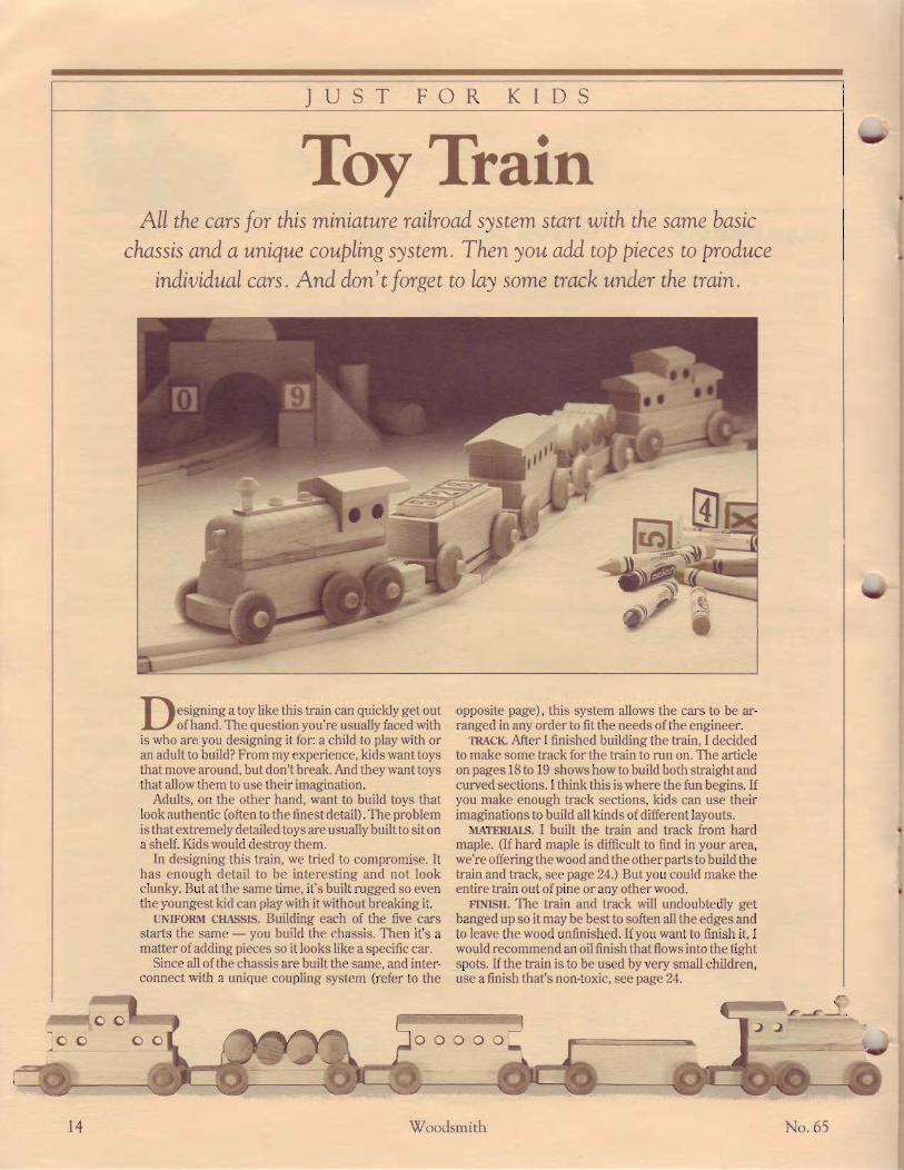
Toy ThainAII the cars for this miniatwe railroad system start with the same basic
chassis and a utnique couplings)stem. Then you add top pieces to produceindiuidual cars . And don' t forget to lay some track under the wain.
v
Y
I f esigning a toy like this train can quickly get outLJ ofhand. The question you're usually faced withis who are you designing it for: a child to play with oran adult to build? From my experience, kids want toysthat move around, but don't break. And they want toysthat allow them to use their imagination.
Adults, on the other hand, want to build toys thatlook authentic (often to the finest detail). The problemisthat extremely detailed toysare usuallybuiltto sitona shelf. Kids would destroy them.
In designing this train, we tried to compromise. Ithas enough detail to be interesting and not lookclunky. But at the same time, it's built rugged so eventhe youngest kid can play with it without breaking it.
UNIFoRM crIAssIS. Building each of the five carsstarts the same - you build the chassis. Then it's amatter of adding pieces so it looks like a specific car.
Since all of the chassis are built the same, and inter-connect with a unique coupling system (refer to the
opposite page), this system allows the cars to be ar-ranged in any order to fit the needs ofthe engineer.
TRAcIL After I finished building the train, I decidedto make some track for the train to run on. The articleon pages 18 to 19 shows how to build both straightandcurved sections. I think this is where the fun begins. Ifyou make enough track sections, kids can use theirimaginations to build all kinds of different layouts.
MATERTAJS. I built the train and track from hardmaple. (If hard maple is dfficult to find in your area,we're offeringthewood and the otherparts to build thetrain and track, see page 24.) Butyou could make theentire train out of pine or any other wood.
FINISH. The train and track will undoubtedly getbanged up so it may be best to soften all the edges andto leave the wood unfinished. If you want to finish it, Iwould recommend an oil finish thatflows into the tightspots. If the train is to be used byvery small children,use afinish that's non-toxic, see page 24.
r4 l7oodsmith No .65

7A2"-DIA.AXIIPEGHQLE5T I I .TT^-.YA'
THE CHASSISi. :: ' , , . ears start with the same' . ,- .c chassis (A). see below.
\ \ l t t . t - t -s . eu t the chass is to- . ' t : : t n r lr i i i the holes for the:i . . . :r t-g: as shown in Step 1.' . . : ' . :- :ht. car was complete, I
mounted the wheels using thetip in the box at right.)
COUPLING. The most chal-lenging part to make is the cou-pling. Each chassis has a holenearthebackend (Steps 2 and 3)
and a tongue on the front (Steps4 to 6). taying out and cuttingthe couplings on the first cartakes a little time. But after cut-ting the first chassis, I used it asa template for laying out the rest.
I Aftet' cutting th,e chassis to size, driLLI lroles .fbr arle pegs centered on the
'1, ickttess. To make su,re the car sits leuel,i-:re 1t tlte topface against Jbncefor all holes.
2?:i;;,r;y;,#f,{:tr!f,,t:;:""f;:,:, 3\f,!;#;li,:,;":!;';t::;il#:"::;i:::;centered 1/J" fy'om the back end. Center theltole onthewidth of th,e clmssis bLank.
to piuot orl c'LLt"Des, cttt toedge-shaped sec-tions oJf tlte end andround lrcLe entrance.
4i;,i:;:,i:#fr":,i;,:,:x;'#{'r:,,:ffi 5I';;I:;,:itr;:;#w;n;T:i7: 6Ti{;":i2::;{:fr'#:!;:;;i:;f';;:;and draw around, the dime. Th,en dratuangled lines dotun.from holes to the edges.
fi\e and sand tr,p to the Lin,e ch,ecking that th.ecouplittg fits easi|y together and piaots.
When mounting the wheelsto the chassis, I use a simpletechnique to keep from driv-ing the axle pegs in too far.
Slip acardboard spacerbe-tween the wheel and chassisand drive the peg in tight.After pulling out the spacer,the gap left allows the wheelto spin without binding.
Note: To keep the wheelsfrom getting in the way whilebuilding the car, I mountedthem afta"the other pieceswere glued to the chassis.TAP AXLE PEGDOWN TIGHT,THEN REMOVECARDBOARDSPACER
--\
ETOCKS PREVENT OPPOSITEPEG FROM BEING DRIVEN IN
COUPTING DETAII
KEEP TOPFACE
JUSI TOUCHEs FRONT \rOF BOTH HOIES
LAY OT'T ANGLED IINEFROM HOIES TO
" BANDSAWOR COPING SAW
I" .l)'om tlrc.front end oJ'the chassisC e r tt er the holes eh o" from each edg e.
Woodsmith 15

ENGINESince the engine pulls the rest of the train, Ibuilt it first. The chassis (A) for the enginerequires a few modifications. First, cut thetongue offthefrontend, see Fig.2.Then dril lanother set ofholes for the tandem wheels.
ITOWER BLocK Start adding top pieces bycutting a lower block (B) from 3/+rr-thickstock that's the same width as the chassis.Then trim an 18" bevel offthe front end andglue the block to the chassis, see Fig. 3.
BoII-ER. Next, the boiler is built up fromtwo lTzrlwide pieces. Cut the 7:urr{hick cen-ter section (C) to length so the front endaligns with the bevel on the lower block (B).
Then cut the.%rr-thick top section (D) 3"long, and round over the front end and sides,see Fig. 5. Now drill holes for the srnoke-stack, fillercaps, and headlights, see Figs. 1and 5. Then glue down the boiler pafls.
CAB. Next, make the cab (E) out of a small
rectangle of 3/+rr-thick stock and drill holesfor the windows, see Fig. 4.
RooF. '[he roof (F) for the engine, the
passenger car, and the caboose are all madethe same, so I cut a blank long enough (13rr)for all three, see Fig. 6. To rnake the roofslope, t i l t the blade (15') and lock the ripfence %" from the blade. Then rip bevels offboth edges. For the engine, cut off a piece2Vt"-long and glue it to the top of the cab.
ROOF(sEE FrG.6)
1(9CAB
(sEE FrC. 4)
towER B[ocK'/l3/4" x l3/4" x 43/4" I
- SMOKESTACK
TOP BOITER(sEE FrC. s)
CENTER BOILERl r / z " x l r / z " x4 r / z " l
PO5tTtONTOWER BIOCK
l /2 'BACK
FRONT OFcHASSrS
, a t/4" DQWEL,
/ | 3za'LONG
A*-.f:lr{EADIIGHTS'}-o.
\ tzr'DowEL,
cHASStS SPACE MIDDIE WHEEL l./8"
DRILL ANOTHER 7zgz" )
AXLE HOLE ON BOTH --
EDGES FOR TANDEM WHEETS
TRIM OFFKNOB
FROM CHASSIS
,o r*o*io--A I
1.
RouNDFRoNrro al l^-stdiHric-; v,1--v/ I ,fl', r
a)^_ \, /
| 3/a"
' .,' '1N\-X
\ ')
DRILL 3/e"
HOIES...- rsnouox
BIOCK FROMBOTH SIDES
(' l,r" RoUND-ovER Blr ROOF BLANK sAvE REsr oF BTANK
TrtT BTADE SECOND: TRIM OFF- To | 5" RooF sEcnoN FoR ENGTNE
COAI CARThe coal car is the easiest to build (and themost fun to play with since it can be loadedwith all types of cargo) . It's just a box gluedto the top of the chassis (A).
CIIT PIECES fi) SIZE. Begin by resawing a13rr-long blank 7+rr-thick for the walls. Thenrip this blank 1rr wide,
Next, cut the two side walls (G) 4.7+rr long
END WALI.S
and the fwo end walls (H) to fit between theside walls, see Fig. 7.
.{SSEMBI-Y. Now, glue the box together,ancl glue it down to the chassis, see Fig. 7.
-
-
Woodsrnith No .65
v

PASSENGER CAR.' I)assenger car, rip 3/4"-thickbottom block(I) andwindowl l r " :Arr re width as the chassis. cut the bottom block (l) 4%"
long and the window block (f) 33larr long.DRILI, WINDOW HOLES. To offer the pas-
sengers an outstanding view of the passingscenery, I dri l led f ive 3/8'r window holes
through the window block, see Fig. 9.noon. Finally, cut off a 43l+r' length of the
roof stock (left from the engine, refer to Fig.6) and glue all the pieces together.
BARRET CAR' . . 'r:. I built a barrel car. It 's designed to hold.::r,.( l \\ 'ooclen barrels. (See page 24 Ior
. ::-\ 'r.s of the barrels.)R \( K.'li) rnake the barrel rack (K), cut a
;,-- BARRET RACKS
CABOOSE\\'hlrt ri'oulcl the end of a train be without a. riiroose? All the parls for the caboose arer::rri lar to pieces made for the other cars.
rr( )TT0M III-OCK. Start by cutting a bottomllkrck (L) the same size as on the passenger. ur ancl glue it lo the chassis, see Fig. 12.
\\ I\I)OW SEL-TION. The window section(\I) rrrt the caboose is a little narrower (11/2tl',iirlt) ancl longer (43l3r' long) than on the: lis('nger car. And there are only four win-jr r\\ 'S on the caboose, see Fig. 12a.
(.\rJ. \ext, cut the cab (N) and dril l the.rindou'holes in it. All the dimensions areiirt. same asthecab on theengineexceptthiseab is only 17:rr wide to match the windowst 'c t ion.
nortn. Finally, cutthree roofsections fromtheroof blank (F) madefortheengine (refer' , , F ig. 6) , and g lue them on top of the. aboose, see Fig. 12.
piece of 7+rr-thick stock 17zrr wicle and 41:7rr i ' llong, see I. ' ig. 11. Next, dri l l four |r-dia. holescentered on the width. And then cut i,/trr-widestrips off both edges of the blank.
--,- s/s" BETWEENINSIDE OF RACKS
r/n"-THICKSTOCK
GTUI DOWNl7e'FROM
ASSEMULY. Now, glue the pieces to thechassis so they're parallel to each other andr,/srr apart. This allows the ribs on the barrelsto rest between the racks.
FRONT OFcHASStS
I 7
WINDOWBLOCK
BOTTOM
GLUE DOWNl3ls" FROM
TT_t+"1 I
t/2"
l T -I ve"? ?
t2 CUT ONE I r./2"-tONG-ROOF PIECE
BOTTOM BTOCK(3/c" x13/c" x43ta"l
, - ---cAB @l 3 / 4 t t x l r / 2 i x l r / 2 r ,
CUT TWO I s/a"-LONGROOF PIECES
-wtNDow sEcTtoNl3/4"x l r /2 "x43/8"1
- DRILL 3/e" -Dl A. HOIES,
GLUE DOWN | 3/8"FROM FRONT OF CHASSIS
WINDOW DETAII-
. 6 r Woodsrnith

PREPARING STOCKThe train can operate on its own, or you canmake a track for it. By making both curvedand straight sections oftrack, you can createa wide variety of interesting layouts.
CURVED TRACK
25Ac"
CUTTTNG THE CURVESAfter the miters are cut on the ends of all thecurve blanks (B), you can set up to cut theinside and outside arcs.
PIvCn JIG. To accurately cut the outsidearcs, I made a pivot jig that sits on top of theband saw. Begin making the jig by cutting a14rr x 18rr pivot board from a piece of 7+r'ply'rvood or Masonite, see Fig.3.
Next, drill a Tarr pivot hole centered on thewidth of the board and |r from the end. Tohelp position the blanks on the jig, nail a107a"long fence to the jig so the/cr edge ofthe fence isl2Vsttfrom the pivot hole.
Now set one ofthe curve blanks on top ofthe jig and align the ends of the blank withthe fence, see Fig. 4. Drive small nails at both
ends of the blank tohold it in place.
IJSINGTHEJIG. Tocu t t he ou ts idecurve, I set the jig ontop of my circle jig(see Wood,srililliNo.51). Or, just clamp apiece of .%r'plywoodto you r band sawtable, see Fig.4.
If you're using theci rc le j ig , posi t ionthe p ivot point 16"f rom the b lade. I f
merger with another railroad line).crir BIANKS. Begin making the track by
cut t ing b lanks f rom Vzt ' s tock for thestraights (A) and curves (B), see Fig. 1.
MITER CUR!T-S. Before cutting the curvepieces (B) to theirrounded shape, I mitered
the ends ofthe blanks, see Fig. 2.To do this, attach an auxiliaryfence to the mitergauge and setthe miter gauge at 22V2" . Thenmiter one end of all the blanks.
To set u! to cut the other end,turn one of the blanks end-for-end and clamp a stopblock to theauxiliary fence, see Fig. 2. Adjustthe stop to trim off the blank soit 's lOTsrrlong on the short side,see Fig. l. Then cut all the curveblanks (B) to this length.
you use the plywood base board, drive a nailthrough the hole in the pivot board and intothebaseboard. (Besuretoalignthenailwiththe.front edge of the blade.)
With a curve blank in place on the jig,swing the pivot board through the blade andcut off the outside arc of the curve, see Fig.4. (Save the waste piece from the end of thepivot board. It's used on the next step.)
cLlT INSIDE ARcs. After cutting the outsidearcs on all the curved pieces and sanding offthe tooth marks, you can cut the inside arcs.
To do this I used the curved waste piece(that was cut off the end of the pivot board)as a fence, see Fig. 5. Position the curvedpiece 23larr from the inside of the blade. (Thiswill cut a curve section Ttorr oversize. Aftersanding, the curves should end up the samewidth as the straights - 2slorr.)
Go ahead and cut all the curve sections towidth. Then sand the inside edge (removingat least ho") so the curved sections matchthe width of the straight sections.
Train ThackA good way to start is to make eight
straight sections (A) and eight curved sec-tions (B). (Eight curves are needed to makea complete circle.) This makes a good sizelayout, and you can add more sections later(as long as the government approves your
| /" l2tte"
-\=1 ..t"
CIAMP ANGLID (2272'lSTOP BI.OCK TO
CLA,MP 3/e" PTYWOOD BASEOR CIRCI.E JIG TO EAND SAW
-'
V
18 Woodsmith No .65
V

RABBETTING EDGES AND ENDS: :' '.'lcit' a path for the train's wheels to. :::. :- l ibbcts are cut on both edges of the, .:
.l', , rlo this. raise a 3/8" rabbet bit Va"., ' : l)r ' rouler table. Then rout the top
;, - ,, iall track pieces, see Fig. 6.| \ l) R.\tJttFtTS. Next, to join the sections of,. .. :, ,{r ' tht'r. connectors are made that f it
' :.: ' l ibbets that are cut in the ends of the
track, refer to photo below.To set up for cutting these rabbets, first
mount a 1346'-wide dado blade on the sawand attach an auxiliary fence to the rip fence,see Fig. 7a. Then bury the blade into theauiliary fence so /1" is exposed.
Now raise the blade up to cut a rabbetexactly deep enough to align with the bot-
tom ofthe rabbets on the edges, see Fig. 7.After the saw was set up, I rabbeted both
ends of the straight track (A) using a mitergauge to supporl the workpiece.
On the curved track (B), I backed up theworkpiece with curved push blocks, see Fig.8. (To make the blocks, trace the shape ofthe curved track onto plyrvood.)
CONNECTORS. ',, in the pieces of track together, small
:.:tr,e tors are made. These connectors are-. ,. i rt 'ctangles of Masonite that f it under
' ,'nd rabbets in the track, see photo atl:::. ' lhere are fwo dowels in each connec-: :, ' f i t in holes in the track.r ( )\\l.l(TORS. Start making the connec-
tors (C) by cutting small rectangles of 7+"-.. k \ lasonite the same width as the track
- t "). see F'ig. 9. As for the length of the: : r f c tors, they ' re t r immed down so' ) r'r' I.i{jrr less than the distance between
' rabbcts on the ends of the track pieces..-:.r: nlrrkes it easier for small fingers to as-- ::rblr the track pieces.
\F:I't l, FOR DRILLING. Next, set up the drill: :.,..s to dri l l 3/s'r holes inthe connectors and
,. track. To do this, make a holcling fence' . lailing two stop blocks to a piece of 2x4.l ' . i t ion the blocks so the connector f its-: . .r sl)' between the stops, see Fig. 10.
\o\\'clamp the2x4 to the clrill press table:- ri ti'nce. Position the fence so the bit is
9 . CONNECIOR
centered between the stop blocks, and thefence is .7urr fron.r the point of the bit.
DRII-I-THE coNNECloRS. Now clrill l7s"dia.holes, .Z o" deep on both edges ofthe connec-tors (C), see Iiig. 10. When drilling, push theconnector tight against the fence.
I)Rll. l . THE TRACK. To dril l the matchingholes in the track, use the same set-up, ex-cept you have to add a k"-thick spacer to fitunder the rabbet in the end of the track. see'Fig. 11. The trick here is to cut the spacerl3lroil wide (which is 7rr;" wider than thelength of the rabbet on the encl of the track) .When the track is pushed againsl the spacer,the hole will be positioned to create a gapbetween the ends of the track. (Again, this isto make it easier to assemble.)
DowEL PINS.'[he last step in making theconnectors is to cut.%rrlong dowelsantlgluethem into the holes in the connectors, seeFig.9.
TRACK SHAPES. The track can be layed outin a variety of shapes, especially if more
pieces are added. However, one layouln.right cause a problem. If you make a sharp"S" shape, the train's cars will probably bindwhen going through the "double-twist"curue.
'fo prevent binding, add a straightsection as a transition betttverr t lte trco C-cir i ' i 'r,s that turn in opposite directions.
DOWEt,3/s"3/a"
I a" HOLE,r ro" DEEP / CENTER
HOIESON
WIDTH
21 td"
1 c " -THICKMASONITE
r3lt6,,- \
/ (t a,4-- I
Woodsmith 19

GIFT PROJECT
OvalBoxThebeauty of this oualboxis thebeveled-edge mirror
that inspired it. The challenge was to figure out a wal to makethe box fit the exact shape of the mirror .
only rout the oval inside the base. This givesyou a few more options for adding a carvingor inlay to the lid of the box.
MAKING THE TEMPLATE
Okay, back to the mirror and template. Tomake a template to rout a recess for the mir-ror, the first step is to trace the shape of themirror on a piece ofpaper, see Step 1.
FoLD oN.o<rs. In order to align the ovalshape on a template, you have to determinethe two axes of the oval. There's a neat trickto do this. Just hold the paper up to a light,see Step 2. The light allors you to see theoval curve on both sides of the paper. Adjustthe paper until the curves align, and fold thesheet in half.
The fold line indicates one axis of the oval.Fold the sheet in half the otherway to get theother axis. fihese axis lines are particularlyimportantfor aligningthe oval in a rectangu-larbox.)
(luas are pleasing shapes - but very\-/difficult to draw. When I decided tomake an oval box, I had two choices. I couldget an oval template from an art store. Or, Icould trace something that already had anoval shape.
The choice was easy when I ran across asource for a beautiful beveled-edge oval mir-ror, see Sources on page 24. With the mirrorin hand, I made an oval box that matched itsshape. This involves making a template tocut a recess in the lid for the mirror. While Iwas at it, I used the same template to rout amatching oval recess in the base.
Design Note: If you don't want to use themirror, but still want to make a box with anoval recess in the base, just get an oval tem-plate from an art store and trace the shape ona piece of Tarr Masonite. Then cut it out andsand itas shown in Step 8 on the nextpage.
There's another option, too. You canmake a rectangular box on the outside and
MARKMIRRoR. Nowyou can use the foldsin the paper to mark the points where theaxis lines meet the edge of the mirror, seeStep 3.
r-ly ollr rEMpuITE. After marking theaxis lines on the mirror, the template can becut from a piece of Vlrr Masonite. (fhe tem-plate shown in Step 4 is sized to accept theoval mirror.)
After cutting the template to size, marktwo cross lines, see Step 4. Now align themarks on the edge of the mirror with thecross lines on the template, see Step 5. Tohold the mirror steady, use a piece of doublesided carpet tape to attach it to the template.
GUIDE BUSHINO
The idea of all this is to use the oval shape ofthe mirror to make a guide template for arouter. This template is then used with aguidebushing that's mounted to the base ofthe router, see Step 6.
v-'
Y'
z0 Woodsmith No.65
v'

Almost all router manufacturers offer aguide bushing (or template guide) that fitson the base oftheir router. This guide bush-ing extends below the base of the router soit can rub against the edge of a template. Theidea is for the guide bushing to follow theshape of the template while the router bit(that fits inside the guide bushing) actuallydoes the cutting.
There's one consideration here. Therouter bit cuts a path that's lizslde the edgeof the bushing. I used a standard bushingwith an outer diameter of Tro".Thisbushingfits around a 7+rr straight bit. Thus, the bitwill cut 3/3'2" from the outside edse of the
bushing, see Detail in Step 6.If you want an e.'-ocf fit, make the template
3/sz" lar ger than the mirror. However, I madethe template 7s" larger than the mirror. Thiscreates a 732'r space around the edge of themirror to allow for expansion of the woodaround the mirror, see Step 7.
Shop Note: I used a piece of cardboard totrace the line Vsrr outside the perimeter ofthe mirror. See Shop Notes on page 12 formore on this technique.
CtnTo SHAPE. To complete the template,cut out the inside to rough shape with eithera sabre saw or a coping saw. Then sand theedges smooth right up to the marked line
with a drum sander mounted in your drillpress, see Step 8.
INDEX HOLES. This template wi l l bemounted to the lid, and then to the base toroutoutthe oval shape.To alignthe templateon both pieces, I drilled two 3/ro" indexholes,see Step 9. These holes are also used later tolocate and drill holes in the lid and base forindex pins to keep the lid from sliding offthebase, refer to Fig. 14.
nrvlss. I finished the lid and the outside ofthe oval box with General Finishes'Two-Step Sealacell system. After f inishing, Iadded a piece of felt to the inside bottom ofthe box.
| | :,:,"'i : ;' ;' 7' : ! i "' ;l i,l" :, :i
","',i,', ! i' i;r
paper. ' I ' l tett trace utrtrt t td t lre lrcr i t treter of 'the nt. inor uit l t a sltut 'p pettci l .
min'or to the centet" Lines. HoLdtlrc mit'r'ot'do'tort tuith a piece of dotftle- sided tape.
th.e outside dia nteter o.fthe bushirry an.dth.eott ts ide d ian t etet' o.l' tlLe b it (.t/.t t" ).
7 ,';zr,f'::i,:{r:?;!';x*lr,{:;r* 8?;,' :,T:#7"!,!f,iT,"{,ffir:::tr ff 9l:#y#:l::Tf"n'z':#'Jr',if,rl!t;mirror. (1/s"Allows :t/:st" for the bushitzgplus th:" arottnd min'or for enpansion.)
coping saw. Then sand carefully up to theLine with a drum sander.
aris. Center the inder holes r/ta" from theedge ofthe oual h,ole.
^fiitT- -:
--'.41f[[*WITH IRACED , \ x' - ONTO EDGEouTr.rNE "- oiivun-ion-
2f,';lf;:;:;;,::,',',,1!:;!iin'i,ii,i,'tl',:inii,'fr,|; 3!l:,{'il,u,!!:,i!;i:,',;f:';!';;::f i,:,':ij;,i;cttraes. ' I ' lLett
. fbld puper i t t hal. f ' to 11et orte t ip perr to rt tark u: l tare t l te u,r ' is l i t res tott t ' l tnl" is.I 'oLrl i t t l teotlrcrtuay.f i t t ' t l teotl teta.vis. theedgeof' t l te t tr inot ' .
DOUBTE-SIDED
CARPETTAPE
ATf ;;H:::;"r;?f,ii::i:,{,?,!):(f:,i,[ 5n#l]fi,r::,":#;,:{;;1,,,f;,,!,}1'f; 6Ti,i:",::;:",::; !,ff;i,,ii i,,,i,1lul;,!tl:,bA /t.l/t" loide) andu,se a square to dt'an cen-ter lines in both directiotts.
-a
6
l/4LTHICK,IAASONITE-
WITH HOI.E%'FRO'\
EUGE _,/tq
t__T-l-" I
l t ll/at L---------)
j
z l
U
No.65 Woodsmith

PREPARE THE BLANKSI started building the box by cutting a blankfor the lid (A) from r/2tt stock to match thesize of the template, see Fig. 1. The base ismade by gluing up fwo pieces: a.t/+"-thickbase (B), and a Tzrlthickbottom (C).
Shop Note: If you can find 6/ 4 stock (thatis 15lrorr thick), you can cut the base out of asolid piece ratherthan laminating two piecestogether. (See Sources, page24.)
U\MINATE. If you have to laminate twopieces to get the thick base, cut both piecesa little oversize. Then glue them together.When the glue is dry, trim the edges downto final size.
MARKPIECES. Before proceeding, I sand-wiched the template between the lid and thebase blank, see Fig. 2. Then I drew a car-penter's triangle on the end of this assembly.This triangle helps align the pieces whendrilling the holes for the alignment pins,refer to l.'igs. 3 and 4.
DRItt INDEX HOTESThe next step is to drill holes in the lid andbase for the indexing pins.
HOI-ES IN uo. Start by lifting the lid andtemplate off the base. Then flip these twopieces over so the template is facing up andtape them together, see Fig.3.
Now with a 3As"-dia. bit, drill holes Vsrldeep into the lid at each end using the holesin the template as a guide.
HOLES IN BASE. Repeat this procedure onthe base. Just place the template on the baseso the sides of the carpenter's triangle alignproperly, see Fig.4.
ROUT RECESSThe index holes are used first to align thetemplate to the lid to rout a recess for themirror, see Fig. 5. Tap index dowels €/ro"-dia.) into the holes, but don't glue them in.
ROtn LID RECESS. To rout out the recessin the lid, use a 74" straight bit and a 746r'guide bushing. Set the bit deep enough so
the face of the mirror will be flush with theedge of the lid (about a .%z'Ldeep recess).
Remove the waste by plunging the routerinto the center of the lid and moving it in aclockwise pattern until you reach the per-imeter of the ten.rplate, see l.'ig. 5.
When you're done, there should be a.%2"-
2
ATIGN EDGESOF AtL
wide lip inside the edge of the template, seeFig. 6. The mirror should fit inside this lipwith about 732rr space all around.
RotlT IIASE. Next rout out the base of thebox the same way, but to a depth of |r. I didthis by making a series of passes abou[ Vrtldeep each time, see Fig. 7.
@BASE
BLANK
Ist/2"
3/4"
\
}.-
tFlVz"
@BOTTOMBTANK
NOTE:GTUE AND CIAMPBOTTOM TO BASE
TEMPLATE t%] DRlrl
\ X"ry1/r MASKINGTAPEArrGN STDES <. l ,4 To KEEP PTECESOF TR1ANG1E \t/ l AltcNED WHttE
-
h l-
2Z Woodsmith No .65
v

-
{t
-
N , r . 6 i Woodsrnith
SHAPE OUTSIDE OF OVAIA t t h i . p o i n t . t h c i n s i d e o f t h e b o x i scurrlrlt'tt'.
-l-ht' next step is to shape the out-
sidc oi thc box to an oval shape as well .TR\( t- o\'.\l-.
-lhe procedure is to lay out an
oval shape on the outside of the box a l i t t lelarger than the inside oval. To do this, I useda cor.npass to trace the shape of the oval onthe lid. Set the compass points 7s'r apart.
Then place the point of the compass in therecessed oval in the lid and trace the shape,see Fig.8.
CUT l-lD To SHAPE. Now cut the lid torough shape on a band saw and sand it care-fully right up to the line with a drurn sanderor on a belt sander.
Ctn IIASE To SHAPE. After sandins the lid
UsE SMOOTHCUT tID SHAPTAS TEMPIATE
OUTTINEONTO BASE
@
171
AIIGN "X" MARKSON tID AND BASE
to shape, place it on the base using the indexpins to align the two pieces, see Fig.9. Nowuse the 1id as a template to trace the oval ontothe base, and cut it out to rough shape on aband saw.
SAND To LINE. 'I'o get the base to the sameshape as the lid, sand them together with adrum sander or on a belt sander, see Fig. 10.
SHADOW LINE AND EDOE PROFIIES'lhe oval box is complete at this point -except for routing profiles on the top edge ofthe l id and the bottom edge ofthe base.
SHAI)ow I.tNIt. However, before I did that,I added a shadow line between the lid andthe base. If either piece warps, this line addsenough depth so the crack between the lidand base is not so visible.
AUXILIARY FENCE. To rout this shadowline, mount a Tzrr straight bit to the routertable and set the bit .%2il high, see Fig. 11a.Then I clamped an auxiliary fence (a piece oI.%rr plywood) to the front of the route r table'sregular fence.
Now turn on the router and slide the auil-iary fence into the bit to rout an opening thewidth of the bit.
To routthe shadowline, turn the routeroffand adjust the fence so the bit extends 3/gz[out, see Fig. 11a. Then rout a rabbet on theto'p otttsid,e edge of the base only to producethe shadow line, refer to Fig. 14a.
ROUND ovER INSIDE EDGE. After routingthe shadow line, I switched to a 7+'r round-over bit and rounded the itlside edge of thebase, see Fie. 12.
OIITSIDE PROFILES. The outside edges o{the base and the lid can be routed to severalshapes. I used 4 i,/4rr rsund-over bit, toachieve a simple and graceful lorik. (Beforeusing other bits, check that their profileswon't cut into the holes for the index pins.)
INDEX PINS. After the edges are routed, Icut two new index pins to fit the holes in thebase, see Fig. 14a.
(;LtlE MIRRoR. Before finishing the box,rnount the mirror into the recess in the lidLrsing a silicone sealant. I also added a pieceof li'lt to the inside bottom of the box and felt(lots to lhe outside bottom of the box.
z3
id;#[. i+ - Y EDGEoFREcESS
,r!r,o\,.Wl.ot$f roSoo*oNTo \JX-ll--.i--f-rz oN ArNDEx 'r-tt-.--l-/ STATIoNARYptNS tN BASE BELT SANDER

PROJECT SUPPLIES
SourcesROGKING HORSE
Woodsmith Project Suppliesis offering a full-size pattern andthe hardware needed to buildthe Rocking Horse shown in thisissue. The pattern provides cut-ting diagrams for all wood andleather parts including instruc-tions on forming the leather intothe saddle and addingthebridle.o 765-15O Rocking Horse
Pattern ..... $Z.gSr 765-1OO Rocking Horse Pat-tern & Hardware Kit..... $49.95(1) Full Size Pattern(25) ilrNails (Ovalhead, Stain-less Steel, Spiral-Shank)(25) Ynn Shples to attach themane and tail(2) Craft Glass Eyes Orown),2{mmdia (approx. 1")(1 Skein) 4-Ply Yarn Orown)(20)#8xlV4rrScrews(16) #8 x 2rr Screws(32) Tail Wood Plugs forScrew Holes(1) Pre-Cut Leather Saddle(2) Pre-Cut Leather Ears(1) | rx 18rr Leather CinchStrap(l) Vz'x 72rr kather BridleStrap(2) 3/t" dia. Nickle-platedD-rings For Bridle(2) ilrx l0rrDowelsOther suppl iers for the
leather and craft glass eyes arelisted below. lnok for code ̂ R.FIfollowing their address.
TOY TRAIN
Woodsmith Project Suppliesis offering the materials andhardware needed to build thefi ve-car Toy Train and Track fea-tured in this issue.
Other suppliers who carry toytrain parts are listed below. tookfor the code TT following thesupplier's name.. 765-2OO Five-Car Train,Parts OnIy........................ $6.95The kit above includes all the
parts Out no lumber) needed tobuild five train cars:
(22) W+'x TrorrWheels(24) V+tt Wheel Axle Pegs(1) s/8" x 17zrr Smoke Stack(tenon fits 7+" hole)(I) V+ttDia. Dowel, 6rrlong(4) Oil Barrels
o 7 65 -225 Five-Car Train,Parts & Lumber............ $18.95This kit contains all the parts
listed above, plus the lumber(maple) to make five cars:
(1 pc.) 33l+rrx 17rr;374tt-15i"1(2 pcs.) 33//4tt xLTttlVztt-thick(lpc.) lt/zttx 18rr; 7+rlthick
o 7 65 -2 5O Train Track Parts& Lumber...................... $Sg.gSThis k i t conta ins enough
maple to produce eight curvedand eight straight track sections.
(8 pcs.) 2\/rctt x l2tt ; Vztt -thick(8 pcs.) 4rr x 15rr; lztt-thick(16 pcs.) F/tattxl7/tatt Mtsonite: V+rr-thick(2) 3/s" x 12rr Dowels
NON-IOXIG FINISHES
You will want to use a non-toxicfinish on the Toy Train andTrack project. Ordinarily, I liketo use a salad bowl finish on toyprojects, but for the train I dis-covered this finish was just toothick to seep in and around allthe small parts of the train. In-stead, we used a finish calledPreserve Nut Oil and found it tobe an ideal fi nish for the train set.
Preserve is a blend of naturaloils from exotic nut meats andprovides an excellent, non-toxicfinish for toys as well as bowlsand wooden kitchen utensils.
There are other finishes thatwill also provide a non-toxic fin-ish and are still thin enough toflow over the small train parts.TWo of these- General Finishes'TwoStep Sealacell System andWatco's Danish Oil - are bothnon-toxic when "cured." (Accord-ing to their manufacturers, thiscan take from two to fourweeks.)
Non-toxic finishes for the toytrain project are available fromWoodsmith Project Supplies,orfrom the sources listed below.took for the code N?followingthe supplier's name.. 7 65-27 5 Preserve Nut Oil
Finish, &o2....................... $S.gS. 518-203 General Finishes'Two-Step System...........$10.95TzPintStep#1 (Sealer)Vz Pint Step #2 (Finish Coat)
OYAI BOX
The materials needed to buildthe Oval Box are available fromWoodsmith Project Supplies.
The oval mirror and siliconesealantcan be ordered using thenumbers below. (We recom-mend using Dow's silicone seal-ant to attach the mirrors sincesome other silicones may dam-age the silvered backs.)o765-3OO (1) 3rrx 5rrBeveled
Oval Mirror ..................... $5.95r765-3O5 (3-oz. tube) Dow
Silicone Sealant (enough to at-tach 80 to 100 mirrors) ... $3.29Also available are lumberkits
in your choice of several differ-ent hardwood species. Each kitincludes the following items:
(l pc.) AVzttx\Vztti Vztt-thicklumber (to make the lid)(l y.) AVztt x 6Vztt ; 1si0"-thicklumber (to make the base)(l) VrcttDowel,4rrlong
o 765-31O Oval Box, Kit ofLumber - Oak ............... $7.95
c 7 65-32O Oval Box, Kit ofLumber - Walnut ......... $8.95
.765-330 Oval Box, Kit ofLumber - Cherry ......... $8.95
.765-340 Oval Box, Kit ofLumber - Padauk........ $12.95(Padauk is an exotic, red-
orange hardwood that turnsdeep maroon on exposure tosunlight. Padauk's sawdust canbe irritating, so using a dust-mask is advised.)
ATTERNATE CATA1OG SOURGESSimilar hard,ware and supplies may befound,
inthefol\owing cataLogs. Howeuer styles and sizes maA aary.Please refer to each catalog for ordering inforrnation.
Van Dyke's RestorersP.O. Box278
CherryTreeToys, Inc.P.O. Box369
Woonsocket, SD 57385 ....... RH Belmont, OH 43718...... .TT, NT
Tandyleather WoodcraftSupplyP.O. Box791 P.O. Box 1686Fort Worth, fi 7 6101-......... R H Parkersburg, WV 26102 . TT, N T
Shopmith,Inc. Bridge CityToolWorks3931 Image Drive 1104 N.E. 28th. Ave.Dayton, OH 45414...... ....TT, NT Portland, OR97232.............. N?
ONDCR INFONNAflONIY MAII BY PHOIII
To order by mail, use the form For faster service use our Tollontheprotectivecoverofacur- Free order line. Phone ordersrent issue or write your order canbeplacedMondaythroughonapieceofpaper,andsendit Friday, 8:00 AM to 5:00 PMwith your check or money CST.order. (Please include $1.50 Before you call, have yourshipping charge with each VISAorMasterCardready.order.) [A residents add 4% l.gi00t ff4_TOOzsales tax. Send order to:WoodmithPnoject$pplies Allw: lto 6 weeksfardntiuary.
P.O. Box 10t150 Note: Prines subjectto chongeDesMoinesrlAs0g06 afizr9lso.
Y
v'
z4 Woodsmith No .65