nobles explorer 1500h oper parts explorer 1500h (06–99) 3 this manual is furnished with each new...
TRANSCRIPT

Carpet Extractor with Heat
Explorer�1500H
Model No.: 608551
Operator and Parts Manual
608564Rev. 00 (09-99)
CUSTOMER SERVICE: 1-800-365-6625FAX: 1–800–678–4240
NOBLES12875 RANSOM STREET HOLLAND MI 49424 U.S.A.


OPERATION
Explorer� 1500H (06–99) 3
This manual is furnished with each new model. Itprovides necessary operation and machinemaintenance instructions and an illustrated parts list.Read this manual completely and understand themachine before operating or servicing it.
Use the illustrated Parts Lists to order parts. Beforeordering parts or supplies, be sure to have yourmachine model number and serial number handy.Parts and supplies may be ordered by phone or mailfrom any authorized parts and service center,distributor or from any of the manufacturer’ssubsidiaries.
This machine will provide excellent service. However,the best results will be obtained at minimum costs if:
� The machine is operated with reasonable care.
� The machine is maintained regularly - per themachine care instructions provided.
� The machine is maintained with manufacturersupplied or equivalent parts.
MACHINE DATA
Please fill out at time of installation for future reference.
Model No.-
Install. Date -
Serial No.-
� 1999 Tennant Company Printed in U.S.A.
Nobles is a registered United States trademark of Tennant Company. Exploreris a United States trademark of Tennant Company.
TABLE OF CONTENTS
SAFETY PRECAUTIONS 4. . . . . . . . . . . . . . . . . . . . . . .
MACHINE SETUP 5. . . . . . . . . . . . . . . . . . . . . . . . . . . . . .
OPERATING FLOOR TOOL 6. . . . . . . . . . . . . . . . . . . . .
OPERATING HAND TOOL 7. . . . . . . . . . . . . . . . . . . . . .
DRAINING MACHINE 7. . . . . . . . . . . . . . . . . . . . . . . . . .
MAINTENANCE 8. . . . . . . . . . . . . . . . . . . . . . . . . . . . . . .
STORING MACHINE 10. . . . . . . . . . . . . . . . . . . . . . . . .
RECOMMENDED STOCK ITEMS 10. . . . . . . . . . . . . .
TROUBLE SHOOTING 11. . . . . . . . . . . . . . . . . . . . . . . .
ELECTRICAL DIAGRAM 12. . . . . . . . . . . . . . . . . . . . . .
PARTS LIST 13. . . . . . . . . . . . . . . . . . . . . . . . . . . . . . . . .
OPTIONAL ACCESSORIES 21. . . . . . . . . . . . . . . . . . .

OPERATION
4 Explorer� 1500H (03–01)
SAFETY PRECAUTIONS
This machine is suited to clean carpet and upholsteryin an indoor environment and is not constructed forany other use. Use only recommended accessorytools and cleaning solutions.
All operators must read, understand and exercise thefollowing Important Safety Instructions.
The following safety alert symbols are used throughoutthis manual as indicated in their description.
WARNING: To warn of hazards or unsafepractices which could result in severe personalinjury or death.
FOR SAFETY: To identify actions which must befollowed for safe operation of equipment.
The following information signals potentially dangerousconditions to the operator or equipment:
FOR SAFETY:
1. Do not operate machine:– Unless trained and authorized.– Unless operator manual is read and
understood.– In flammable or explosive areas unless
designed for use in those areas.– With damaged cord or plug.– If not in proper operating condition.– In outdoor areas.– In standing water.– With the use of additional extension cords.
Only use manufacturer’s extension cordequipped with machine which has propercapacity and is grounded.
2. Before operating machine:– Make sure all safety devices are in place
and operate properly.
3. When using machine:– Do not run machine over cord.– Do not pull machine by plug or cord.– Do not pull cord around sharp edges or
corners.– Do not unplug by pulling on cord.– Do not stretch cord.– Do not handle plug with wet hands.– Keep cord away from heated surfaces.– Report machine damage or faulty
operation immediately.– Follow mixing and handling instructions
on chemical containers.
4. Before leaving or servicing machine:– Turn off machine.– Unplug cord from wall outlet.
5. When servicing machine:– Unplug cord from wall outlet.– Avoid moving parts. Do not wear loose
jackets, shirts, or sleeves.– Use manufacturer supplied or approved
replacement parts.
WARNING: Hazardous Voltage. Shock orelectrocution can result. Always unplug machinebefore servicing.
WARNING: Flammable materials can causean explosion or fire. Do not use flammablematerials in tank(s).
WARNING: Flammable materials or reactivemetals can cause an explosion or fire. Do not pickup.
GROUNDING INSTRUCTIONS:
This machine must be grounded. If it shouldmalfunction or breakdown, grounding provides apath of least resistance for electrical current toreduce the risk of electric shock. This machine isequipped with a cord having anequipment–grounding conductor and groundingplug. The plug must be plugged into anappropriate outlet that is properly installed inaccordance with all local codes and ordinances.Do not remove ground pin, if missing replace plugbefore use.
Grounded Outlet
Grounding Edge/hole
Grounded3 Hole Outlet
Ground Pin
(120V) (230V/240V)

OPERATION
Explorer� 1500H (04–99) 5
MACHINE SETUP
1. Unscrew and remove front clear lid. Fill solutiontank bladder with 57 L (15 gal) of hot water, 60°C(140°F) max. Add recommended cleaning agentto proper dilution ratio (Figure 1).
FOR SAFETY: When using machine, follow mixingand handling instructions on chemical containers.
FIG. 1
WARNING: Flammable materials can causean explosion or fire. Do not use flammablematerials in tank(s).
NOTE: After filling solution tank bladder, replace clearlid and tighten securely. Suction in recovery tank willoverexpand solution tank bladder if lid is not sealed.
ATTENTION: Do not mix powdered chemicals inextractor’s solution tank bladder. Mix powderedchemicals thoroughly in a bucket before pouringinto machine. Powders are unlikely to dissolvecompletely and can clog solution pump system.
NOTE: If using a bucket to fill and empty machine useseparate buckets. Always use a clean bucket to fillmachine. Dirty water in solution tank bladder will clogsolution pump system.
2. Connect two 7.6 m (25 ft) extension power cordsinto machine.
FOR SAFETY: Do not operate machine with theuse of additional extension cords. Only usemanufacturer’s extension cord equipped withmachine which has proper capacity and isgrounded.
3. Plug each extension cord into separate groundedcircuits. Circuit indicator lamp (green) will lightwhen cords are on separate circuits (Figure 2).
ATTENTION: When plugging extension cords intoreceptacles be certain to use separate circuits.This will prevent a circuit overload. Do notactivate heater if green indicator does not light.
FIG. 2
4. Prime solution pump:a. Connect bleeder hose onto solution quick
coupler located at front of extractor.b. Submerge other end of bleeder hose into a
bucket or back into solution tank.c. Open rear pressure adjustment knob
completely, turn counterclockwise, then turnpump switch on. As pump runs, air bubblesshould dissipate in solution (Figure 3).
d. Close pressure adjustment knob completelyby turning clockwise and allow pump tocontinue running. If properly primed, pressureshould read 200–220 psi.
e. Now attach accessory tool.
NOTE: Whenever extractor runs out of solution whileoperating, you must always prime pump beforeoperating.
FIG. 3
5. Preheat solution. To maintain or to increasesolution temperature before operating extractor,rotate preheat/clean knob to read “PREHEAT”(Figure 4). Activate “PUMP” and “HEATER”switches. Solution temperature will riseapproximately 0.55�C (1�F) per minute with a fullsolution tank. Maximum achievable solutiontemperature is approximately 66�C (150�F).

OPERATION
6 Explorer� 1500H (04–99)
FIG. 4
6. Attach vacuum and solution hose to hoseconnectors at front of machine then to floor orhand tool (Figure 5).
FIG. 5
7. Turn “PUMP” and “HEATER” switches off whensolution reaches up to a maximum temperature ofapproximately 66�C (150�F). Rotate preheat/cleanknob to read “CLEAN” (Figure 6). While operating,the “CLEAN” mode will raise the existing solutiontemperature approximately 11�C (20�F) at thespray tips. Example: A solution tank temperatureof 66�C (150�F) will increase to a maximumtemperature of approximately 77�C (170�F) atthe spray tips.
ATTENTION: DO NOT switch from “PREHEAT” to“CLEAN” mode when pump switch is activated,pump and gauge damage may occur (not coveredby warranty). Always turn pump switch off beforeturning preheat/clean knob.
FIG. 6
NOTE: In order to get optimum water heat at spraytips while operating, keep preheat/clean knob in“CLEAN” mode. Cleaning in “PREHEAT” mode will notharm machine, this will only prevent optimum waterheat at spray tips.
OPERATING FLOOR TOOL
FOR SAFETY: Do not operate machine unlessoperator manual is read and understood.
NOTE: Vacuum carpet before cleaning.
1. Activate “VACUUM”, “PUMP” and “HEATER”switches.
NOTE: Be certain that circuit indicator light is on toverify that two separate circuits are being used.
2. Place floor tool so bottom of glide plate orstainless steel shoes are parallel to floor. Squeezetrigger and apply downward pressure on floor toolhead and slowly pull tool backwards using bothhands. Release trigger 152 mm (6 in) from end ofstroke (Figure 7).
WARNING: Flammable materials or reactivemetals can cause explosion or fire. Do not pickup.
FIG. 7
3. Push floor tool forward over same path with triggerreleased when returning for next stroke. Continuethis pull and push method with a slight overlap ofeach stroke.
NOTE: For heavily soiled areas, repeat stroke orchange angle of stroke.
ATTENTION: Do not allow water or foam to entervacuum motor. Float shut-off screen will not stopfoam intake and vacuum motor damage will result(not covered by warranty). If foam develops,remove rear clear lid and pour 30 ml (1 oz) ofanti-foam solution into recovery tank.
4. When finished cleaning, turn off switches anddrain recovery tank (See DRAINING MACHINE).
OPERATION
Explorer� 1500H (04–99) 7
5. Disconnect solution and vacuum hoses frommachine and neatly coil hoses for storing.
ATTENTION: Relieve water pressure from toolbefore disconnecting hose. Squeeze trigger forfive seconds after turning off switches.
OPERATING HAND TOOL
FOR SAFETY: Do not operate machine unlessoperator manual is read and understood.
NOTE: This machine cleans most synthetic upholsteryvery well. Fabrics like Herculon and synthetic velvetswill clean with excellent results. Extraction is notrecommended for most cottons, silks, wools or naturalfiber velvets. Check cleaning instructions sewn infurniture by manufacturer for further instructions.Extra caution should be taken with furniture that hasbeen re–upholstered. Any material under newupholstery may bleed and discolor new fabric.
NOTE: Vacuum upholstery before cleaning.
1. TEST FABRIC FOR COLORFASTNESS: Pour asmall amount of cleaning solution on a white cloth.Hold damp portion of cloth against an area ofupholstery which is hidden from view. Hold itthere for 60 seconds. If no color transfers to cloth,it should be safe to clean. However, always useyour best judgement.
ATTENTION: Be certain the circuit indicator lightis on to verify that two separate circuits are beingused.
2. Activate “VACUUM”, “PUMP” and “HEATER”switches.
3. Adjust pressure valve knob to read 30 psi onpressure gauge (Figure 8).
FIG. 8
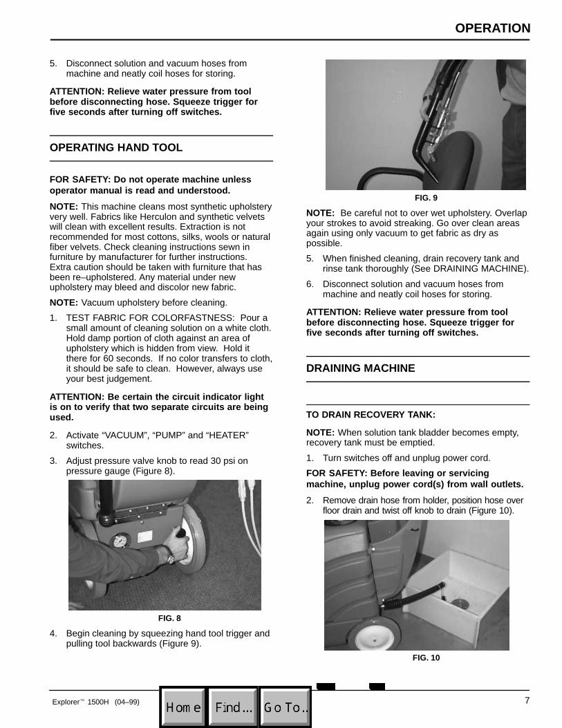
4. Begin cleaning by squeezing hand tool trigger andpulling tool backwards (Figure 9).
FIG. 9
NOTE: Be careful not to over wet upholstery. Overlapyour strokes to avoid streaking. Go over clean areasagain using only vacuum to get fabric as dry aspossible.
5. When finished cleaning, drain recovery tank andrinse tank thoroughly (See DRAINING MACHINE).
6. Disconnect solution and vacuum hoses frommachine and neatly coil hoses for storing.
ATTENTION: Relieve water pressure from toolbefore disconnecting hose. Squeeze trigger forfive seconds after turning off switches.
DRAINING MACHINE
TO DRAIN RECOVERY TANK:
NOTE: When solution tank bladder becomes empty,recovery tank must be emptied.
1. Turn switches off and unplug power cord.
FOR SAFETY: Before leaving or servicingmachine, unplug power cord(s) from wall outlets.
2. Remove drain hose from holder, position hose overfloor drain and twist off knob to drain (Figure 10).
FIG. 10
OPERATION
8 Explorer� 1500H (04–99)
NOTE: If using bucket to drain machine, do not usesame bucket for filling clean water bladder!
3. Replace knob tightly before cleaning again.
4. After final draining, remove recovery tank lid andrinse tank and shut off float screen thoroughly.
TO DRAIN SOLUTION TANK:
1 . To drain remaining solution from solution tank,disconnect solution hose and attach bleeder hose(bleeder hose supplied with machine).
ATTENTION: Before disconnecting solution hoseand replacing with bleeder hose, relieve waterpressure from tool before disconnecting hose.Squeeze trigger for five seconds after turning offswitches.
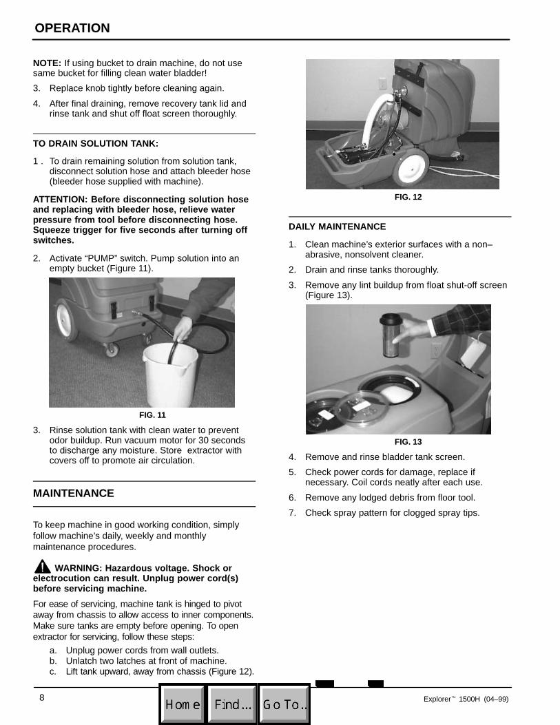
2. Activate “PUMP” switch. Pump solution into anempty bucket (Figure 11).
FIG. 11
3. Rinse solution tank with clean water to preventodor buildup. Run vacuum motor for 30 secondsto discharge any moisture. Store extractor withcovers off to promote air circulation.
MAINTENANCE
To keep machine in good working condition, simplyfollow machine’s daily, weekly and monthlymaintenance procedures.
WARNING: Hazardous voltage. Shock orelectrocution can result. Unplug power cord(s)before servicing machine.
For ease of servicing, machine tank is hinged to pivotaway from chassis to allow access to inner components.Make sure tanks are empty before opening. To openextractor for servicing, follow these steps:
a. Unplug power cords from wall outlets.b. Unlatch two latches at front of machine.c. Lift tank upward, away from chassis (Figure 12).
FIG. 12
DAILY MAINTENANCE
1. Clean machine’s exterior surfaces with a non–abrasive, nonsolvent cleaner.
2. Drain and rinse tanks thoroughly.
3. Remove any lint buildup from float shut-off screen(Figure 13).
FIG. 13
4. Remove and rinse bladder tank screen.
5. Check power cords for damage, replace ifnecessary. Coil cords neatly after each use.
6. Remove any lodged debris from floor tool.
7. Check spray pattern for clogged spray tips.

OPERATION
Explorer� 1500H (11–99) 9
WEEKLY MAINTENANCE
1. Remove and soak spray tips in a tannin solution.
ATTENTION: Do not use pins, paper clips, etc., tounplug spray tips. This will damage spray tips.
2. Flush pump system: Use a tannin solution todissolve normal alkaline chemical buildup. Followsteps below:
FOR SAFETY: When using machine, follow mixingand handling instructions on chemical containers.
a. Mix 500 ml (16 oz) of tannin solution with 7.6 L(2 gal) of hot water 60o C (140o F) maximuminside solution tank.
b. Place a bucket under spray jets to catchspray.
c. Turn on “PUMP” switch.d. Squeeze trigger on tool for 30 seconds.e. Allow solution to remain in system for up to 6
hours in above freezing temperatures.f. Later, spray out tannin solution into a drain.
Then run 11.4 L (3 gal) of clean water throughsystem to flush out impurities.
3. Check floor tool for loose shoes. If loose, tap withrubber mallet.
4. Inspect vacuum hose for holes and loose cuffs.
5. Grease pump: Solution pump must be greasedevery 40 hours of operation or monthly, whichevercomes first. Refer to hour meter located belowhandle of machine to help you determine whengreasing is necessary. Each new machine issupplied with a grease gun. (Grease Gun Part No.190022).a. To grease pump, release latches on front of
machine and lift tank to access pump.b. Remove safety cover by pinching tabs and
pulling straight off. You will also need toremove black plug from front of chassis.
c. Insert grease gun through plug hole (front ofchassis) and onto grease fitting, pump plungerat most 1 to 2 times. Gun only pumps greaseat last 19 mm (0.75 in) of plunger travel. Besure to push plunger all the way down! Do thisslowly to allow grease to enter bearing (Figure 14).
ATTENTION: Overgreasing pump will damageseals.
ATTENTION: Do not use an air powered or handlever grease gun, they will damage pump.
FIG. 14
d. With a screwdriver, apply a generous dab ofgrease to outer diameter of cam bearing at topand bottom where bearing contactsconnecting rod.
e. Replace grease cover and black plug.f. Check pump periodically and scrape out (do not
wash out) any excess grease from pump cavity.
MONTHLY MAINTENANCE
1. Inspect cord grips for damage. Replace ifdamaged. Neatly coil cords after each use.
2. Inspect tank for cracks.
3. Lubricate casters with a water resistant grease.
EVERY 250 HOURS OF OPERATION
Check vacuum motor for carbon brush wear. Replacebrushes when worn to a length of 10 mm (0.38 in) orless.

OPERATION
10 Explorer� 1500H (06–99)
STORING MACHINE
Store extractor with clear lids off to promote aircirculation.
ATTENTION: Do not expose to rain. Store indoors.
ATTENTION: DO NOT ALLOW MACHINE TOFREEZE WITH WATER IN PUMP SYSTEM. Thiscan crack internal parts and cause damage, whichis not covered by warranty.
STORING MACHINE IN FREEZINGTEMPERATURES
1. Drain tanks thoroughly.
2. Pour 1 L (32 oz) undiluted antifreeze into waterbladder.
3. Place a bucket under spray jets to catch spray.
4. Turn on “PUMP” switch.
5. Squeeze trigger on tool for 30 seconds.
6. Allow antifreeze to remain in system.
RECOMMENDED STOCK ITEMS
Refer to Parts List section for recommended stockitems. Stock Items are clearly identified with a bulletpreceding the parts description. See example below:
OPERATION
Explorer� 1500H (04–99) 11
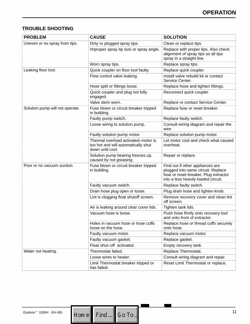
TROUBLE SHOOTING
PROBLEM CAUSE SOLUTIONUneven or no spray from tips. Dirty or plugged spray tips. Clean or replace tips.
Improper spray tip size or spray angle. Replace with proper tips. Also checkalignment of spray tips so all tipsspray in a straight line.
Worn spray tips. Replace spray tips.Leaking floor tool. Quick coupler on floor tool faulty. Replace quick coupler.
Flow control valve leaking. Install valve rebuild kit or contactService Center.
Hose split or fittings loose. Replace hose and tighten fittings.Quick coupler and plug not fullyengaged.
Reconnect quick coupler.
Valve stem worn. Replace or contact Service Center.Solution pump will not operate. Fuse blown or circuit breaker tripped
in building.Replace fuse or reset breaker.
Faulty pump switch. Replace faulty switch.Loose wiring to solution pump. Consult wiring diagram and repair the
wire.Faulty solution pump motor. Replace solution pump motor.Thermal overload activated–motor istoo hot and will automatically shutdown until cool.
Let motor cool and check what causedoverheat.
Solution pump bearing freezes up,caused by not greasing.
Repair or replace.
Poor or no vacuum suction. Fuse blown or circuit breaker trippedin building.
Find out if other appliances areplugged into same cIrcuit. Replacefuse or reset breaker. Plug extractorinto a less heavily loaded circuit.
Faulty vacuum switch. Replace faulty switch.Drain hose plug open or loose. Plug drain hose and tighten knob.Lint is clogging float shutoff screen. Remove recovery cover and clean lint
off screen.Air is leaking around clear cover lids. Tighten tank lids.Vacuum hose is loose. Push hose firmly onto recovery tool
and onto front of extractor.Holes in vacuum hose or hose cuffsloose on the hose.
Replace hose or thread cuffs securelyonto hose.
Faulty vacuum motor. Replace vacuum motor.Faulty vacuum gasket. Replace gasket.Float shut–off activated. Empty recovery tank.
Water not heating. Thermostat failed. Replace Thermostat.Loose wires to heater. Consult wiring diagram and repair.Limit Thermostat breaker tripped orhas failed.
Reset Limit Thermostat or replace.

ELECTRICAL DIAGRAM
12 Explorer� 1500H (04–99)
120V Wiring
ON
OFF
VACUUM HEATER
SOLUTIONPUMP
PUMP
��
��
��
��
�
���
�
HEATER
POWERCORD
POWERCORD
�������
�����
HOURMETER
INDICATORLIGHT
��
��
��
��
�
���
�
VACUUMMOTOR
BL
KR
ED
RE
D
RE
D
BL
K
BLK
WHT
GRNGRN
GRN
WHTGRN
BLK
GRN
BLKWHT
BL
K
BL
K
WH
TW
HT
RE
D
GR
N
BL
KB
LK
WHT
RED BLK
BLK
WHT
GRN
GRN
WH
T
BL
K
BLK
GRN
WH
T

PARTS LIST
13Explorer� 1500H (04–99)
HANDLE GROUP
8
1
23
4
5
6
7 9
10
1113
1214
15
19
16
1718
REF PART # DESCRIPTION QTY.
1 130227 �CORD, 14/3 X 20” YELLOW 2
2 130166 �CORD GRIP, NYLON/BLK W/NUT 2
3 608557 HANDLE, GREEN 1
4 130691 �LIGHT, INDICATOR – GREEN 1
5 19417 �SWITCH, WITH ON/OFF 3
6 120189 DECAL, DASH 1
7 230908.BK PLATE, REAR COVER BLACK 1
8 140519 NUT 10–24 KEP 3
9 140900 SCREW 10–24X3/4 TRSPHL 1
10 120619 DECAL, WARNING EXTRACTORS 1
REF PART # DESCRIPTION QTY.
11 140197 SCREW 10–24X3/8 TRSPHL 4
12 140825 SCREW #6X1/2 PANPHL 2
13 230696.BK BRACKET, DRAIN HOSE HANGER 1
14 130017 METER, HOUR–RECTANGULAR 1
15 140825 SCREW #6X1/2 PANPHL 2
16 140231 SCREW, HXHDCP 3/8X1–1/2 4
17 140017 WASHER 3/8 SPLTLCK 4
18 140028 WASHER 3/8 FLT 4
19 130694 �CORD, EXT 14/3X25’ YELLOW 2
� ����������� �����

PARTS LIST
14 Explorer� 1500H (04–99)
UPPER HOUSING GROUP
3
20
2122
23
19
18
24
1
2
4
5
6
7
8
9
10
11
12
13
14
15
16
17
25
27
28
29
31
32
33
44
42
43
41
40
37
36
38
39
35 34
26
30

PARTS LIST
15Explorer� 1500H (06–99)
UPPER HOUSING GROUP
REF PART # DESCRIPTION QTY.
∇ 100103 CLEAR LID, W/CNTRSNK HOLES 1
�1 100109 LID OUTER RING 1
�2 100105 � LID, CENTER ONLY CLEAR 1
3 120190 DECAL, “USE BLEEDER HOSE” 1
4 120907 DECAL, “IMPORTANT...” 1
5 140900 SCREW, 10–24X3/4 TRSPHL 6
6 140000 WASHER, 1/4 FLT 6
7 602783 BLADDER 1
8 602448 STANDPIPE W/NIPPLE 1
9 180613 � FLOAT, SHUT–OFF 1
10 606088 FITTING 1–1/2” NIPPLE 1
11 101714 GASKET, WASTE AIR CHAMBER 1
12 210240 NUT, FLANGED METAL 1–1/2 1
13 100102 � CLEAR LID W/STANDARD HOLE 1
14 120907 DECAL, IMPORTANT–ALWAYS... 1
15 120906 DECAL, IMPORTANT–DRAIN... 1
16 140825 SCREW, #6X1/2 PANPHL 6
∇ 590965 KIT, DRAIN HOSE COMPLETE 1
�17 160627 HOSE, DRAIN 1
�18 140072 CLAMP, 1 9/16 STEPLESS 2
�19 140921 SLEEVE, DRAIN HOSE 1
∇ � 501061 � ASM DRAINHOSE STOPPER 1
�20 230831 KNOB, DRAIN HOSE 1
�21 230882 STRAP, DRAIN STOPPER 1
REF PART # DESCRIPTION QTY.
�22 140056 WASHER 3/8IDX1.50OD FNDR 1
�23 140955 PLUG, DRAIN HOSE 1
24 140307 CLAMP, HOSE 3/4 TO 1–3/4 1
25 608475 DECAL, EXPLORER 1500H 2
26 608555 TANK, RECOVERY, GREEN 1
27 230845 PLATE, CORD CLAMP 1
28 140834 SCREW 1/4–20X5/8 FLTPHL 1
29 140258 SCREW 1/4–20X4–1/4 STUD 3
30 140134 BUSHING .375ODX.250IDX.270THK 2
31 230846 BRACKET, TANK SUPPORT 1
32 140000 WASHER 1/4 FLT 1
33 140016 WASHER 1/4 LCK 1
34 140554 SCREW 1/4–20X3/4 HXHDCP 1
35 140524 NUT 1/4–20 KEP 1
36 140259 SCREW 1/4–20X5/8 HXHDCP 3
37 140016 WASHER 1/4 LCK 3
38 230946 BRACKET, TANK BRACE FRONT 1
39 608186 DECAL, “NOBLES” LOGO 1
40 140932 � LATCH, HOOD W/ KEEPER 2
41 140801 SCREW 8–32X3/8 TRSPHL 4
42 140023 WASHER #8 INT 4
43 140703 RIVET, POP 3/16 X .251–.375 1
44 230905 TUBE, INLET 1
∇ �������
� ����������������
� ����������� �����

PARTS LIST
16 Explorer� 1500H (04–99)
LOWER HOUSING GROUP
1
2
345
6
7
8
910
11
12
1314
15 16
17
1821
2119
20
2427
22
27
25
26
28
2930
31
32
3334
35
36
37
38
39
40
54
41
574344
45
43 12
11
53
56
50
46
47
49
48
51
54
55
52
42
23

PARTS LIST
17Explorer� 1500H (06–99)
LOWER HOUSING GROUP
REF PART # DESCRIPTION QTY.
1 180100 PUMP, TWIN PISTON 1
2 140823 SCREW 10–24X5/8 TRSPHL 2
3 140506 NUT 5/16–18 HEX 4
4 140027 WASHER 5/16 FLT 8
5 140015 WASHER 5/16 SPLTLCK 8
6 130450 MOTOR, PUMP DRIVE 1/3 HP (120V) 1
130453 MOTOR, PUMP DRIVE (230V) 1
7 130031 MOUNT, MOTOR 1–1/4” 4
8 100001 �GASKET VAC MOTOR 7.2 1
9 130096 TERMINAL, ML DSCNT 2
∇ 10 130404 �MOTOR, VAC 7.2/3 STAGE (120V) 1
� 190157 �BRUSH,CARBON 2/PK 2
∇ 130405 MOTOR, VAC 7.2/3 STAGE (230V) 1
� 190157 BRUSH,CARBON 2/PK 2
11 140308 CLAMP, HOSE 1–5/16 TO 2–1/4 2
12 160629 �HOSE 2” X 28” WHITE 1
13 140501 NUT, 1/4–20 NYLOCK 3
14 102567 �GASKET, VAC MOTOR INTAKE 1
15 230390 HINGE, TANK 1
16 140000 WASHER 1/4 FLT 4
17 140885 SCREW 1/4–20X1/2 TRSPHL 7
∇ 18 210108 VALVE, PRESSURE CONTROL 1
�19 210023 KNOB, NEEDLE VALVE 1
20 140894 SCREW, SCST CPPT 10–32X1/4 1
21 27820 WASHER, FLAT .687 ID X 1.50 OD 2
22 140552 NUT 10–24 NYLCK 1
23 140328 CLAMP, 3/8” NYLON 1
24 140196 SCREW 10–24X1 TRSPHL 1
25 606659 GAUGE,PRESSURE 0–600 PSI 1
26 140825 SCREW #6X1/2 PANPHL 3
27 140519 NUT 10–24 KEP 4
REF PART # DESCRIPTION QTY.
28 140196 SCREW 10–24X1 TRSPHL 1
29 230907 AXLE, 18” 1
30 140008 WASHER 1/2 FLT 4
31 103009 �WHEEL, 12” X 1.75 WHITE/GRAY 2
32 140000 WASHER 1/4 FLT 2
33 140016 WASHER 1/4 LCK 2
34 140885 SCREW 1/4–20X1/2 TRSPHL 2
35 230746 BRACKET AXLE OFFSET 2
36 140016 WASHER 1/4 LCK 4
37 140259 SCREW 1/4–20X5/8 HXHDCP 4
38 103065 �CASTER, SWIVEL 4” 2
39 140016 WASHER 1/4 LCK 8
40 140259 SCREW 1/4–20X5/8 HXHDCP 8
41 140223 SCREW 5/16–18X3/4 HXHDCP 4
42 140869 SCREW 10–24X1–3/4 PANPHL 2
43 140011 WASHER 3/16 FLT 4
44 130284 PLUG, DOME 1.00” BLACK 1
45 140932 KEEPER (PART OF LATCH) 2
46 140023 WASHER #8 INT 4
47 140801 SCREW 8–32X3/8 TRSPHL 4
48 150933 FITTING, 1/4F QD PLUG BRS SER60 1
49 140823 SCREW 10–24X5/8 TRSPHL 2
50 140058 WASHER .543X.875X.062 WAND 1
51 120123 DECAL, CAUTION PRESSURE 1
52 608553 CHASSIS, GREEN 1
53 140918 SPACER .20X.31X1.00 2
∇ 54 180440 HEATER, 1700W (120V) COMPLETE 1
180441 HEATER 1700W (230V) COMPLETE 1
� 102566 INSULATOR, HEATER 1
55 102568 STRAP, NYLON W/ ADHESIVE 1
56 101288 COVER HEATER 1
∇ �������
� ����������������
� ����������� �����

PARTS LIST
18 Explorer� 1500H (04–99)
PLUMBING GROUP
21
3
5
2
4
13
67
12
9
8
11
10
14
1516
17
6
3
18
19
20
2423
22
21
13
46
476
1
45
44
26
13
48
25
49
51
50
25
27
28
29
31
30
32
38
39
4034
35
17
16
3641
4342
25
37
40
26
44
25
33

PARTS LIST
19Explorer� 1500H (04–99)
PLUMBING GROUP
REF PART # DESCRIPTION QTY.
1 606359 HOSE 1/4ID X 8” GRAY L.P. 1
2 140325 CLAMP, EAR 1/2” 3
3 606161 HOSE 1/4 X 36” GRAY L.P. 1
4 150713 TEE, UNION 1/4” BARB NYLON 1
5 606244 HOSE 1/4IDX16” LP 1
6 140305 CLAMP, HOSE 7/32–5/8 DIAM 3
7 150418 FITTING, 1/4MX1/4H ELBOW 90 BRS 1
8 27820 WASHER, FLAT .687 ID X 1.50 OD 2
∇ 9 210108 �VALVE, PRESS CNTRL W/NUT 1
�10 210023 �KNOB, NEEDLE VALVE 1
�11 140894 �SCREW, SCST CPPT 10–32X1/4 1
12 606987 FITTING, 1/4”NPTM X 1/4”INV.FL 1
13 606666 ASM PRESSURE GAUGE TUBE 1
14 603186 �SCREEN CLEAN WATER TANK 1
15 600452 PLATE BLADDER ASM 1
16 140310 CLAMP, HOSE 5/16–7/8 2
17 603051 HOSE, 29”LONG REINFORCED 1
18 140000 WASHER 1/4 FLT 4
19 140016 WASHER 1/4 LCK 4
20 140259 SCREW 1/4–20X5/8 HXHDCP 4
21 606665 FITTING, GAUGE ADAPTER 1
22 606660 �FITTING, GAUGE SNUBBER 1
23 606659 �GAUGE, PRESSURE 0–600 PSI 1
24 140825 SCREW #6X1/2 PANPHL 3
25 606663 HEATER OUTLET TUBE W/NUT 1
26 600546 FERRULE S/S FOR #600545 2
27 130692 CONTROL, THERMOSTAT 1
REF PART # DESCRIPTION QTY.
28 140197 SCREW 10–24X3/8 TRSPHL 2
29 101288 COVER HEATER 1
30 6032.6 SCREW 8–32X3/8 PANPHL 4
31 130693 LIMIT, THERMOSTAT 1
∇ 32 180440 �HEATER, 1700W (120V) CMPLT 1
180441 HEATER, 1700W (230V) COMPLETE 1
� 102566 INSULATOR, HEATER 1
33 102568 STRAP, NYLON W/ ADHESIVE 1
34 130450 �MOTOR, PUMP DRIVE (120V) 1
130453 MOTOR, PUMP DRIVE (230V) 1
35 190310 �PUMP, SHAFT KEY 5300 SERIES 1
36 150431 FITTING 1/2MX1/2H ELBOW 90 1
37 180100 �PUMP, TWIN PISTON 1
38 150405 FITTING 1/2MX1/2F ELB STRT90 1
39 150101 FITTING 1/2MX1/4F BUSHING 1
40 160140 �HOSE, PULSE 36” 1
41 700141 �HOSE BLEEDER SERIES 60 1
42 140058 WASHER .543X.875X.062 WAND 1
43 150933 �FITTING 1/4F QD PLUG SER60 1
44 606664 HEATER INLET TUBE W/NUT 1
45 606662 MANIFOLD, PRESSURE RELIEF 1
46 210211 VALVE, PRESSURE RELIEF 1
47 150525 FITTING 1/8MX1/4H BARB 1
48 606987 FITTING, 1/4”NPTM X 1/4”INV.FL 1
49 210043 �VALVE, BALL 3–WAY 1/4” BRASS 1
50 120198 DECAL, CLEAN – VALVE KNOB 1
51 120199 DECAL, PREHEAT – VALVE KNOB 1
∇ �������
� ����������������
� ����������� �����
PARTS LIST
20 Explorer� 1500H (04–99)
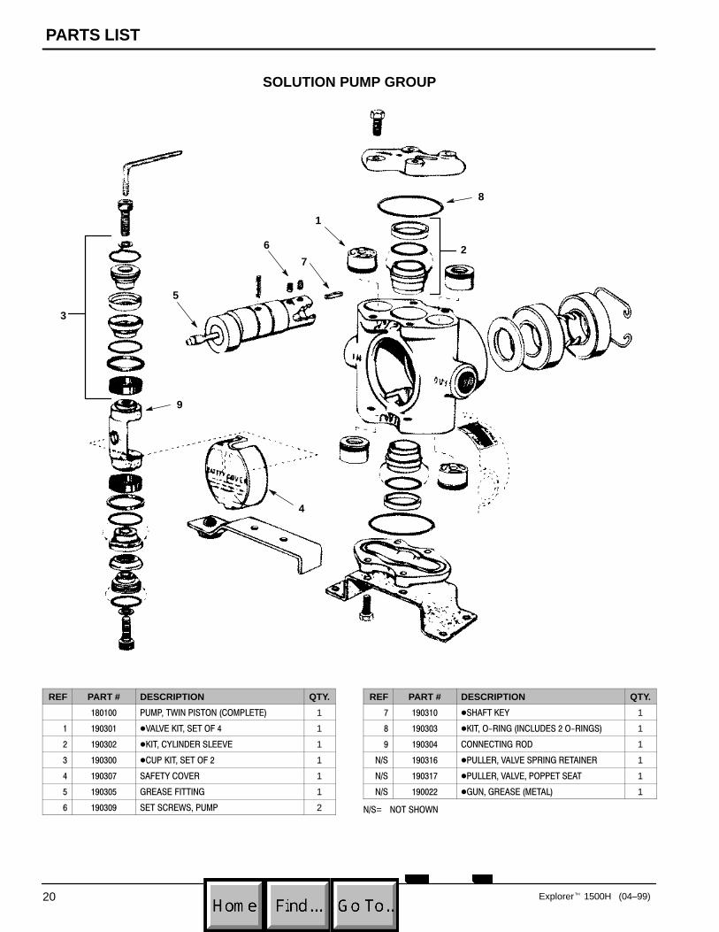
SOLUTION PUMP GROUP
8
1
4
7
6
5
2
9
3
REF PART # DESCRIPTION QTY.
������ �������������������������� 1
� ������ ������ ����������� 1
� ������ � �������������� 1
� ������ ����� ����������� 1
� ����� ���������� 1
! �����! "����������" 1
# ������ �������������� 2
REF PART # DESCRIPTION QTY.
������ ��$���� � 1
� ������ � �����%���"������������%���"�� 1
� ������ ��������"��� 1
�&� �����# ������������������"������� 1
�&� ����� ����������������������� 1
�&� ������ �"����"���������� 1
�&�= �����$���

OPTIONAL ACCESSORIES
21Explorer� 1500H (10–96)
127 mm (5 in) UPHOLSTERY TOOL ASSEMBLY
10
211
12
13
985
4
3
6
1
7
14
REF PART # DESCRIPTION QTY.
200505 TOOL, 5” HAND (COMPLETE) 1
1 200431.BK TOOL, 5” HAND 1
2 150913 COUPLER, QUICK, SER. 60 1
3 150615 NIPPLE, CLOSE 1
4 200905 LEVER, K–VALVE W/PIN 1
5 210210 VALVE, FLOW CONTROL 1
6 190600 VALVE PIN & SPRING (NOT SHOWN) 1
7 210148 CAP, HEX, VALVE 1
REF PART # DESCRIPTION QTY.
8 150606 NIPPLE, HEX 1/4” 1
9 150403 ELBOW, ST 1/4” 45° 1
10 200992 BODY, SPRAY 1/4”F 1
11 200996 SCREEN, SPRAY BODY 1
12 200965 TIP, BRASS #8002 1
13 200994 CAP, SPRAY BODY 1
14 140609 PIN, ROLL 3/16 X 9/16 1
��&��NOT SHOWN

OPTIONAL ACCESSORIES
22 Explorer� 1500H (10–96)
HIGH PRESSURE FLOOR TOOL ASSEMBLY
11
4
5
1
2
26
20
15
16
19
18
2122
23
25
24
10
9
14
1312
86
7
3
17
REF PART # DESCRIPTION QTY.
600049 TOOL, 13” FLOOR (COMPLETE) 1
1 200403.BK TOOL, 13” FLOOR 1
2 200939 SHOES, FLOOR TOOL 2
3 200927 GRIP, ADJUSTABLE COMPLETE 1
4 200912 FOAM, GRIP 1
5 140259 SCREW, 1/4 X 5/8 2
6 200902 TRIGGER, FLOOR TOOL 1
7 200809 SLEEVE, TRIGGER 1
8 140605 PIN 1
140520 NUT, PUSH 2
9 210150 VALVE, FLOW CONTROL 1
10 190603 KIT, VALVE PIN & SPRING 1
11 N/A CAP, HEX, VALVE 1
12 150403 ELBOW, 1/4–45� 1
13 150615 NIPPLE, CLOSE 1/4 1
REF PART # DESCRIPTION QTY.
14 150913 COUPLER, QUICK SER. 60 1
15 160175 HOSE, SOLUTION HP 1
16 140058 WASHER 1
∇ 17 700062 ASM., SPRAY BAR 1
�18 150401 ELBOW, 90� 1/4F X 1/4F 2
�19 150600 NIPPLE 2
�20 150700 CROSS 1
�21 200993 SPRAY BODY 3
22 200996 SCREEN, SPRAY BODY 3
23 200986 TIP, SPRAY (#9502) 2
24 200988 TIP, SPRAY (#11002) 1
25 200994 CAP, SPRAY BODY 3
26 140834 SCREW, 1/4–20 X 5/8 2
N/S 120845 DECAL, “HIGH PRESSURE” 1
∇ �������
� �����������������&��NOT SHOWN

OPTIONAL ACCESSORIES
23Explorer� 1500H (10–96)
SOLUTION AND VACUUM HOSES
1
4
2
3
6
5
REF PART # DESCRIPTION QTY.
∇ 1 160191 SOUTION HOSE 25’ 1
�2 150913 COUPLER, QUICK SER. 60 1
�3 150933 PLUG, QUICK COUPLER 1
�4 150615 NIPPLE 2
∇ 5 160401 HOSE, VACUUM W/ CUFFS 25’ 1
�6 160430 CUFF, HOSE 1–1/2” 2
N/S 160451 CONNECTOR, VAC HOSE 1–1/2” 1
∇ �������
� �����������������&��NOT SHOWN